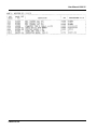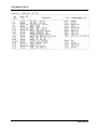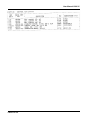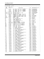
1
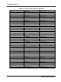
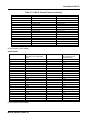
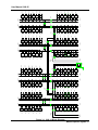
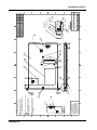
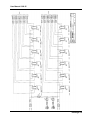
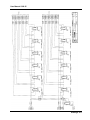
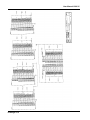
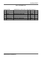
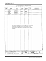
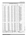
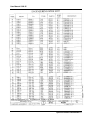
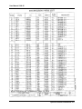
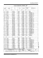
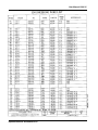
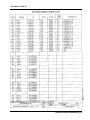
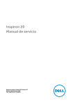
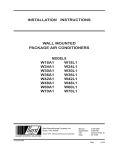
1260 VXI
SWITCHING CARD
1260-35
MULTIPLEXER / SCANNER
PUBLICATION NO. 980673-006
RACAL INSTRUMENTS
Racal Instruments, Inc.
4 Goodyear St., Irvine, CA 92618-2002
Tel: (800) 722-3262, FAX: (949) 859-7309
Racal Instruments, Ltd.
480 Bath Road, Slough, Berkshire, SL1 6BE, United Kingdom
Tel: +44 (0) 8706 080134; FAX: +44 (0) 1753 791290
Racal Systems Electronique S.A.
18 Avenue Dutartre, 78150 LeChesnay, France
Tel: +33 (1) 3923 2222; FAX: +33 (1) 3923 2225
Racal Systems Elettronica s.r.l.
Strada 2-Palazzo C4, 20090 Milanofiori Assago, Milan, Italy
Tel: +39 (02) 5750 1796; FAX +39 (02) 5750 1828
Racal Elektronik System GmbH.
Frankenforster Strasse 21, 51427 Bergisch Gladbach, Germany
Tel:+49 2204 92220; FAX: +49 2204 21491
Racal Australia Pty. Ltd.
3 Powells Road, Brookvale, NSW 2100, Australia
Tel: +61 (2) 9936 7000, FAX: +61 (2) 9936 7036
Racal Electronics Pte. Ltd.
26 Ayer Rajah Crescent, 04-06/07 Ayer Rajah Industrial Estate, Singapore 0513.
Tel: +65 7792200, FAX: +65 7785400
Racal Instruments, Ltd.
Unit 5, 25F., Mega Trade Center, No 1, Mei Wan Road, Tsuen Wan, Hong Kong, PRC
Tel: +852 2405 5500, FAX: +852 2416 4335
http://www.racalinst.com
PUBLICATION DATE: April 10, 2000
Copyright 1997 by Racal Instruments, Inc. Printed in the United States of America. All rights reserved.
This book or parts thereof may not be reproduced in any form without written permission of the publisher.
WARRANTY STATEMENT
All Racal Instruments, Inc. products are designed and manufactured to exacting standards and in full
conformance to Racal’s ISO 9001 procedures.
For the specific terms of your standard warranty, or optional extended warranty or service agreement, contact
your Racal customer service advisor. Please have the following information available to facilitate service.
1.
Product serial number
2.
Product model number
3.
Your company and contact information
You may contact your customer service advisor by:
E-Mail:
[email protected]
Telephone:
+1 800 722 3262
+44(0) 8706 080134
+852 2405 5500
(USA)
(UK)
(Hong Kong)
Fax:
+1 949 859 7309
+44(0) 1628 662017
+852 2416 4335
(USA)
(UK)
(Hong Kong)
RETURN of PRODUCT
Authorization is required from Racal Instruments before you send us your product for service or calibration. Call
your nearest Racal Instruments support facility. A list is located on the last page of this manual. If you are
unsure where to call, contact Racal Instruments, Inc. Customer Support Department in Irvine, California, USA at
1-800-722-3262 or 1-949-859-8999 or via fax at 1-949-859-7139. We can be reached at:
[email protected].
PROPRIETARY NOTICE
This document and the technical data herein disclosed, are proprietary to Racal Instruments, and shall not,
without express written permission of Racal Instruments, be used, in whole or in part to solicit quotations from a
competitive source or used for manufacture by anyone other than Racal Instruments. The information herein has
been developed at private expense, and may only be used for operation and maintenance reference purposes or
for purposes of engineering evaluation and incorporation into technical specifications and other documents which
specify procurement of products from Racal Instruments.
FOR YOUR SAFETY
Before undertaking any troubleshooting, maintenance or exploratory procedure, read carefully the
WARNINGS and CAUTION notices.
This equipment contains voltage hazardous to human life and safety, and is capable of inflicting
personal injury.
If this instrument is to be powered from the AC line (mains) through an autotransformer, ensure the
common connector is connected to the neutral (earth pole) of the power supply.
Before operating the unit, ensure the conductor (green wire) is connected to the ground (earth)
conductor of the power outlet. Do not use a two-conductor extension cord or a three-prong/twoprong adapter. This will defeat the protective feature of the third conductor in the power cord.
Maintenance and calibration procedures sometimes call for operation of the unit with power applied
and protective covers removed. Read the procedures and heed warnings to avoid “live” circuit
points.
Before operating this instrument:
1. Ensure the instrument is configured to operate on the voltage at the power source. See
Installation Section.
2. Ensure the proper fuse is in place for the power source to operate.
3. Ensure all other devices connected to or in proximity to this instrument are properly grounded or
connected to the protective third-wire earth ground.
If the instrument:
-
fails to operate satisfactorily
shows visible damage
has been stored under unfavorable conditions
has sustained stress
Do not operate until performance is checked by qualified personnel.
This page was left intentionally blank.
NOTE FOR SYSTEMS WITH 1260-OPT 01T
The “Module-Specific Syntax” section of this manual shows the command syntax for the
1260-01S Smart Card. If you are using the newer 1260-01T Smart Card, the commands
will NOT work as shown.
Consult the 1260-01T Manual for a description of the commands that may be used with the
1260-01T Smart Card.
The channel numbers described in this manual are valid for the 1260-01T. The channel
numbers continue to be used for the 1260-01T.
The syntax of the commands that use channel numbers has changed for those cards
controlled by the 1260-01T.
The new syntax used to close a channel is:
CLOSE (@ <module address> ( <channel> ) )
For example, for a relay module whose <module address> is set to 7, closing <channel> 0
is performed with the command:
CLOSE (@7 (0))
Using the older 1260-01S, the command would be (as shown in this manual):
CLOSE 7.0
Many other command syntax differences exist. Please consult chapter 2 of the 1260-01T
manual for a description of the commands that are available for the 1260-01T.
Amendment Page 6/98
1
Control Information for the 1260-35A
The 1260-35A operates as a 4-wire MUX. Thus, when a channel is operated, 2 relays must be operated in
parallel. For each channel, when a bit of Control Register X is set (or cleared), the same bit of Control
Register X+6 must also be set (or cleared).
Each channel on this module is therefore controlled by setting or clearing two bits, one each in two different
Control Registers. Control Registers on the module operate 8 channels simultaneously. There are eight
control bits per Control Register. Setting the bit to a 1 closes the relay; setting the bit to a 0 opens the relay.
The table below shows the mapping between logical channels used to operate the relay module in messagebased mode and the bits within the Control Registers which may be used to operate the channel in registerbased mode.
Each Control Register is located 2 addresses from the previous Control Register. That is, each Control
Register is located at an odd address. This is shown in Table 2-2 of the 1260-01T manual. Control Register 0
is located at the “Base A24 Address” for the module. Consult the “Register-Based Operation” Section of
Chapter 2 of the 1260-01T manual for a description of calculating control register addresses
For example, when closing channel 13, both byte 1 and byte 7 must have bit 5 set.
Channel
0
1
2
3
4
5
6
7
8
9
10
11
12
13
14
15
16
17
18
19
20
21
22
23
24
25
26
27
28
29
30
31
32
33
34
35
36
37
38
39
Control Register
0 and 6
0 and 6
0 and 6
0 and 6
0 and 6
0 and 6
0 and 6
0 and 6
1 and 7
1 and 7
1 and 7
1 and 7
1 and 7
1 and 7
1 and 7
1 and 7
2 and 8
2 and 8
2 and 8
2 and 8
2 and 8
2 and 8
2 and 8
2 and 8
3 and 9
3 and 9
3 and 9
3 and 9
3 and 9
3 and 9
3 and 9
3 and 9
4 and 10
4 and 10
4 and 10
4 and 10
4 and 10
4 and 10
4 and 10
4 and 10
Control Bit
0
1
2
3
4
5
6
7
0
1
2
3
4
5
6
7
0
1
2
3
4
5
6
7
0
1
2
3
4
5
6
7
0
1
2
3
4
5
6
7
Channel
40
41
42
43
44
45
46
47
Control Register
5 and 11
5 and 11
5 and 11
5 and 11
5 and 11
5 and 11
5 and 11
5 and 11
Control Bit
0
1
2
3
4
5
6
7
Control Information for the 1260-35B
The following information describes the control-register-to-relay-channel mapping for a 1260-35B Relay
Module. This information may be used to control a 1260-35B when using a 1260-01T in the register-based
mode of operation.
Each relay on this module is controlled by setting or clearing a single bit within a Control Register. Control
Registers on the module operate 8 channels simultaneously. There are eight control bits per Control Register.
Setting the bit to a 1 closes the relay; setting the bit to a 0 opens the relay.
The table below shows the mapping from logical channels to control bits. The logical channels are used when
operating the relay module in message-based mode. The control bits within the Control Registers are used to
operate the module in register-based mode.
Each Control Register is located 2 addresses from the previous Control Register. That is, each Control
Register is located at an odd address. This is shown in Table 2-2 of the 1260-01T manual. Control Register 0
is located at the “Base A24 Address” for the module. Consult the “Register-Based Operation” Section of
Chapter 2 of the 1260-01T manual for a description of calculating control register addresses.
Channel
0
1
2
3
4
5
6
7
8
9
10
11
12
13
14
15
16
17
18
19
20
21
22
23
24
25
26
27
28
29
30
31
32
33
34
35
36
37
38
39
40
41
42
43
Control Register
0
0
0
0
0
0
0
0
1
1
1
1
1
1
1
1
2
2
2
2
2
2
2
2
3
3
3
3
3
3
3
3
4
4
4
4
4
4
4
4
5
5
5
5
Control Bit
0
1
2
3
4
5
6
7
0
1
2
3
4
5
6
7
0
1
2
3
4
5
6
7
0
1
2
3
4
5
6
7
0
1
2
3
4
5
6
7
0
1
2
3
Channel
44
45
46
47
48
49
50
51
52
53
54
55
56
57
58
59
60
61
62
63
64
65
66
67
68
69
70
71
72
73
74
75
76
77
78
79
80
81
82
83
84
85
86
87
88
89
90
91
92
93
94
95
96
Control Register
5
5
5
5
6
6
6
6
6
6
6
6
7
7
7
7
7
7
7
7
8
8
8
8
8
8
8
8
9
9
9
9
9
9
9
9
10
10
10
10
10
10
10
10
11
11
11
11
11
11
11
11
12
Control Bit
4
5
6
7
0
1
2
3
4
5
6
7
0
1
2
3
4
5
6
7
0
1
2
3
4
5
6
7
0
1
2
3
4
5
6
7
0
1
2
3
4
5
6
7
0
1
2
3
4
5
6
7
0
User Manual 1260-35
Table of Contents
Chapter 1
MODULE SPECIFICATION .......................................................................................................... 1-1
1260-35 Module Specification ................................................................................................... 1-1
Specifications ........................................................................................................................ 1-2
Ordering Information ................................................................................................................. 1-3
Safety........................................................................................................................................ 1-3
Product Support ........................................................................................................................ 1-3
Chapter 2
INSTALLATION INSTRUCTIONS ................................................................................................ 2-1
Unpacking and Inspection ......................................................................................................... 2-1
Reshipment Instructions............................................................................................................ 2-1
Option 01 Installation ................................................................................................................ 2-2
Module Installation .................................................................................................................... 2-2
1260-35 ID Byte ........................................................................................................................ 2-2
Configuration............................................................................................................................. 2-2
Analog Bus................................................................................................................................ 2-4
Chapter 3
MODULE SPECIFIC SYNTAX...................................................................................................... 3-1
1260-35 Module Specific Syntax ............................................................................................... 3-1
Syntax ................................................................................................................................... 3-1
CLOSE Command ................................................................................................................. 3-2
PSETUP Command............................................................................................................... 3-2
PDATAOUT Command.......................................................................................................... 3-2
Operation In Single-Wire Mode ............................................................................................. 3-3
Chapter 4
DRAWINGS.................................................................................................................................. 4-1
Chapter 5
PARTS LIST ................................................................................................................................. 5-1
i
User Manual 1260-35
Chapter 6
OPTIONAL HARNESS ASSEMBLIES.......................................................................................... 6-1
Chapter 7
PRODUCT SUPPORT ................................................................................................................. 7-1
Product Support........................................................................................................................ 7-1
Reshipment Instructions ........................................................................................................... 7-1
Support Offices ......................................................................................................................... 7-2
ii
User Manual 1260-35
List of Figures
Figure 1-1, 1260-35 Signal Multiplexer/Scanner Module............................................................... 1-1
Figure 3-1, 1260-35 Block Diagram .............................................................................................. 3-7
Figure 3-2, 1260-35 Pin Connections, Front View......................................................................... 3-8
List of Tables
Table 2-1, 1260-35 Jumper Installation......................................................................................... 2-3
Table 3-1, 1260-35 Channel Closure ............................................................................................ 3-3
Table 3-1, 1260-35 Channel Closure (continued) ......................................................................... 3-5
Table 3-1, 1260-35 Channel Closure (continued) ......................................................................... 3-6
iii
User Manual 1260-35
This page was left intentionally blank.
iv
User Manual 1260-35
Chapter 1
MODULE SPECIFICATION
1260-35 Module
Specification
The 1260-35 Signal Multiplexer/Scanner Module is a 1 x 96
multiplexer. It switches two lines per channel and has the
capability of being configured as two 1 x 48 multiplexers, four 1 x
24 multiplexers, eight 1 x 12 multiplexers, or sixteen 1 x 6
multiplexers. The configuration is user selectable, but is supplied
by the factory in one 1 x 96 two-wire mode. A block diagram of the
module is shown in Figure 3-1
Figure 1-1, 1260-35 Signal Multiplexer/Scanner Module
Module Specification 1-1
User Manual 1260-35
Specifications
Switch Configurations
Four-wire Mode
Two-wire Mode
User Connector
Any configuration
Any configuration
64-Pin (2 Row)
IDC Quick Disconnect
Maximum Switchable Voltage
220VDC, 250VAC RMS
(Terminal-Terminal or Terminal-Chassis
Maximum Switchable Current
1A DC or 1A RMS
Maximum Switchable Power
Per Channel
30W DC, 62.5VA AC
Path Resistance
<0.5Ω (1 X 6 configuration)
<1.0Ω (1 X 96 configuration)
Isolation Hi-Lo
>7.5 X 10⁸Ω
Capacitance
Open Channel
Channel-Chassis
Hi-Lo
Bandwidth (50Ω Termination)
<600pf (1 x 96 configuration)
<60pf (1 x 6 configuration)
<200pf (1 x 96 configuration)
<50pf (1 x 6 configuration)
<600pf (1 x 96 configuration)
>50 MHz (1 x 6 configuration)
>15 MHz (1 x 48 configuration)
* A crimp connector kit is also available for this module (PIN
404975-001). A strain relief option can be ordered separately for
this crimp connector kit.
Insertion Loss (50Ω )
1 x 6 Configuration
<.1 dB to 100kHz
<.5 dB to 1MHz
<1 dB to 10MHz
Insertion Loss (50Ω )
1 x 96 Configuration
<3 dB to 8MHz
Crosstalk (50Ω termination)
<-90 dB to 100kHz
<-70 dB to 1 MHz
<-23 dB to 10MHz
Cooling Requirement
Module Specification 1-2
User Manual 1260-35
Airflow
Backpressure
4.0 liters/sec
0.5mm H20
Power Requirements
+5V, Ipm
+24V, Idm
Weight
0.4A (2.8A with Option 01 installed)
10mA per energized relay
3.07lbs (1.33Kg)
3.35lbs (1.51Kg) with Option 01 installed
Minimum Option 01 Firmware
Revision
17.1
Ordering
Information
Model Number
Description
Part Number
1260-35
1 X 96 Signal Multiplexer/
Scanner, User Conn: IDC
1 X 96 Signal Multiplexer/
Scanner, User Conn: Crimp
404944
1260-35A
404944-001
Safety
Refer to the “FOR YOUR SAFETY” page preceding the Table of
Contents. Following all NOTES, CAUTIONS, and WARNINGS to
ensure personal safety and prevent damage to the instrument.
Product Support
Racal Instruments has a complete Service and Parts Department.
If you need technical assistance or should it be necessary to return
your product for servicing, call 1-800-722-3262. If parts are
required to repair the product at your facility, call 1-949-859-8999
and ask for the Parts Department
When sending your instrument in for repair, complete the form in
the back of this manual.
Module Specification 1-3
User Manual 1260-35
This page was left intentionally blank.
Module Specification 1-4
User Manual 1260-35
Chapter 2
INSTALLATION INSTRUCTIONS
Unpacking and
Inspection
1. Before unpacking the switching module, check the exterior of
the shipping carton for any signs of damage. All irregularities
should be noted on the shipping bill.
2. Remove the instrument from its carton, preserving the factory
packaging as much as possible.
3. Inspect the switching module for any defect or damage.
Immediately notify the carrier if any damage is apparent.
4. Have a qualified person check the instrument for safety before
use.
CAUTION
Proper ESD handling procedures must always be
used when packing, unpacking or installing any 1260
Series cards. Failure to do so may cause damage to
the unit.
Reshipment
Instructions
1. Use the original packing material when returning the switching
module to Racal Instruments for servicing. The original
shipping carton and the instrument's plastic foam will provide
the necessary support for safe reshipment.
2. If the original packing material is unavailable, wrap the
switching module in plastic sheeting and use plastic spray
foam to surround and protect the instrument.
3. Reship in either the original or a new shipping carton.
Installation Instructions 2-1
User Manual 1260-35
Option 01
Installation
Installation of the Option 01 to the 1260-35 is described in the
Installation section of the 1260 Series VXI Switching Cards
Manual.
Module
Installation
Installation of the 1260-35 Switching Module into a VXI mainframe,
including the setting of DIP switches, is described in the
Installation section of the 1260 Series VXI Switching Cards
Manual. Configuration of the PCBA and setting of the DIP switches
SW1-5 and SW1-6 are described in the following sections.
1260-35 ID Byte
Each configuration responds to different sets of values for
<channel number>. The set of values the 1260-35 responds to is
controlled by switch 5 on DIP switch 51 on the PCB. The switch
settings that correspond to the two configurations are as follows:
Configuration
Configuration
S1 Switch 5 S1 Switch 6
Four-wire
Off
Off
Two-wire
On
Off
The 1260-35 Scanner~u1tiplexer is a user configurable switching
module. Ten different configurations are available as follows:
1)
Sixteen 1 x 6 two-wire scanner/multiplexers, P/N 404944-206
2)
Eight 1 x 6 four-wire scanner/multiplexers, P/N 404944406
3)
Eight 1 x 12 two-wire scanner/multiplexers, P/N 404944-212
4)
Four 1 x 12 four-wire scanner/multiplexers, P/N 404944-412
5)
Four 1 x 24 two-wire scanner/multiplexers, P/N 404944-224
6)
Two 1 x 24 four-wire scanner/multiplexers, P/N 404944-424
7)
Two 1 x 48 two-wire scanner/multiplexers, P/N 404944-248
8)
One 1 x 48 four-wire scanner/multiplexers, P/N 404944448
9)
One 1 x 96 two-wire scanner/multiplexers, P/N 404944-296
10)
One 1 x 192 one-wire scanner/multiplexers, P/N 404944
Unless otherwise specified, the 1260-35 is shipped from the
factory in the 1 x 192 single wire configuration. Table 2-1 gives the
Installation Instructions 2-2
User Manual 1260-35
necessary information to configure the module into the other
possible configurations
Table 2-1, 1260-35 Jumper Installation
An X indicates a jumper is to be fitted. An (X) indicates the jumper is optional depending on
whether access to the analog bus is required. A blank indicates no jumper is to be fitted.
16(1x6)
2-wire
8(1x6)
4-wire
8(1x12)
2-wire
4(1x12)
4-wire
4(1x24)
2-wire
2(1x24)
4-wire
W2A, B
W3A, B
X
X
W4A, B
W5A, B
X
X
2(1x48)
2-wire
1(1x48)
4-wire
1(1x96)
2-wire
(X)
(X)
(X)
X
X
X
X
X
X
X
X
X
X
X
X
X
X
X
X
X
X
W6A, B
W7A, B
W8A, B
X
X
X
W9A, B
W10A, B
X
X
X
X
X
X
X
X
X
X
X
X
X
X
X
X
X
1(1x192)
1-WIRE
ONLY--->
X
X
X
X
X
X
X
X
X
X
X
X
X
X
X
X
W11A, B
W12A,B
X
X
W13A, B
W14A, B
X
X
W15A, B
X
W16A, B
W17A, B
X
X
W18A, B
W19A, B
W20A, B
X
X
X
X
X
X
X
X
X
X
X
X
X
X
X
X
X
X
X
X
(X)
(X)
(X)
Installation Instructions 2-3
User Manual 1260-35
Analog Bus
In most of the above configurations, the 1260-35 may be user
configured to access an analog bus (refer to Figure 3-1). The
analog bus allows internal expansion for the configuration of larger
scanner/multiplexers than the module may achieve alone, by
providing access to a common bus channel which may be daisy
chained to other modules via the front panel.
To connect the module to the analog bus, install jumpers W2A,
W2B, W20A, and W20B.
Installation Instructions 2-4
User Manual 1260-35
Chapter 3
MODULE SPECIFIC SYNTAX
1260-35 Module
Specific Syntax
The Module Specific Syntax for the 1260-35 is required in the use
of the OPEN and CLOSE commands. It will also appear in data
output by the Master in response to the PDATAOUT and PSETUP
commands.
Syntax
The Module Specific Syntax for the 1260-35 Signal
Multiplexer/Scanner module is as follows:
OPEN <module address>.<channel>[;<module address>.
<channel>]
where <module address> is the switch card address.
<channel> is the relay to be closed to connect an input to
the output.
Note that Channels remain closed until opened by an OPEN
command, RESET command, VXI hard or soft reset, or power-off.
NOTE
The <module address> used here is NOT the VXIbus
defined logical address of the 1260 Series Master. It
is peculiar to the 1260 Series and describes the
switching module in relation to the Master. This
address corresponds to the binary value of the switch
setting of SW1 on the switching module PCB.
The range of values for <channel> is:
One-wire
Two-wire
Four-wire
00-96
00-95
00-47
The actual mapping of number to connector pins is given in Table
3-1. Figure 3-1 shows the physical location of the various
connector pins.
Module Specific Syntax 3-1
User Manual 1260-35
Example:
OPEN 3.02
This open command will open channel 2 on the module at switch
card address 3
CLOSE Command
The Module Specific Syntax for the CLOSE command is the same
as for the OPEN command.
PSETUP
Command
The PSETUP command causes the specified module setup to be
transmitted to the VXI Controller. The syntax used is:
PSETUP <module address>[;<module address>] [;<module
address>] where <module address> is the address.
The responses to the PSETUP command for the 1260-35
Multiplexer/Scanner is as follows:
1260-35:
Two-wire
<module address>. 1260-35B, Two-wire Scanner/Multiplexer
Module
<module address>. BBM
<module address>.END
1260-35:
Four-wire
<module address>. 1260-35A, Four-wire Scanner/Multiplexer
Module
<module address>. BBM
<module address>.END
The response to the PSETUP command consists of a header on
the first line. The header describes the model number followed by
an A or B designating four or two-wire, respectively. The next line
designates the setup mode for scanning which, by default, is
Break-Before-Make (BBM). The last line containing the "END"
characters denotes no more information to report.
PDATAOUT
Module Specific Syntax 3-2
The PDATAOUT command causes the specified module to
transmit the CLOSED state of the relays within the switching
User Manual 1260-35
Command
module to the 1260 Controller. The syntax used is:
PDATAOUT <module address>[.<module address>]
[;<module address>]…..
The responses to the PDATAOUT command is as follows:
1260-35:
Two-wire
<module address>. 1260-3 SB Two-wire Scanner/Multiplexer
Module
<module address>. <channel>[,<channel>] [,<channel>]
<module address>.END
1260-35
Four-wire
<module address>. 1 260-35A Four-wire Scanner/Multiplexer
Module
<module address>. <channel>[,<channel>] [,<channel>]
<module address>.END
The response to the PDATAOUT command consists of a header
on the first line as with the PSETUP response. The next line
details the channels currently closed on the module and is blank
when no channels are closed. Again, the last line is denoted by the
"END" string of characters.
Operation In
Single-Wire Mode
The 1260-35 is delivered with all jumpers installed (refer to Table
2-1). In this configuration, the module is a 1 x 96 two-wire
multiplexer (refer to Figure 3-1).
Channel 97 is a single pole, double throw (SPDT) relay with its
common channel connected to J202, pin B2. The normally closed
(NC) contact is connected to the "LO" side of the two-wire
common bus, and the normally open (NO) contact is connected to
the "HI" side of the common bus.
The common output of channel 96 is the single channel of the 192
x 1 multiplexer, and the 96 HI and 96 LO connections make up the
192 channels. By closing the appropriate channel (0-95) and
opening or closing channel 96. a 192 x 1 multiplexer is achieved.
Example:
CLOSE
CLOSE
3.46
3.96
This would correct J202 pin B2 to J202 pin A4
Table 3-1, 1260-35 Channel Closure
Module Specific Syntax 3-3
User Manual 1260-35
channel interconnect for 1, 2 and 4-wire modes.
1-wire mode:
<channel>
(channel 96 open)
0 thru 95
(channel 96 closed)
0 thru 95
<channel> output
<channel> input
always J202- B2
(see 2-wire mode channels 0-95
input pins b-side of channel)
always J202- B2
(see 2-wire mode channels 0-95
input pins a-side of channel)
Thus, a one 1 x 191 1-wire mode is acheived.
2-wire mode:
channel>
0
1
2
3
4
5
6
7
8
9
10
11
12
13
14
15
16
17
18
19
20
21
22
23
24
25
26
27
28
29
Module Specific Syntax 3-4
<channel> output pins
a / b
(HI)
(Lo)
J200- A30 / B30
J200- A30 / B30
J200- A30 / B30
J200- A30 / B30
J200- A30 / B30
J200- A30 / B30
J200- A23 / B23
J200- A23 / B23
J200- A23 / B23
J200- A23 / B23
J200- A23 / B23
J200- A23 / B23
J200- A16 / B16
J200- A16 / B16
J200- A16 / B16
J200- A16 / B16
J200- A16 / B16
J200- A16 / B16
J200- A9 / B9
J200- A9 / B9
J200- A9 / B9
J200- A9 / B9
J200- A9 / B9
J200- A9 / B9
J202- A30 / B30
J202- A30 / B30
J202- A30 / B30
J202- A30 / B30
J202- A30 / B30
J202- A30 / B30
to
<channel> input pins
a / b
(HI)
(LO)
J200- A29 / B29
J200- A28 / B28
J200- A27 / B27
J200- A26 / B26
J200- A25 / B25
J200- A24 / B24
J200- A22 / B22
J200- A21 / B21
J200- A20 / B20
J200- A19 / B19
J200- A18 / B18
J200- A17 / B17
J200- A15 / B15
J200- A14 / B14
J200- A13 / B13
J200- A12 / B12
J200- A11 / B11
J200- A10 / B10
J200- A8 / B8
J200- A7 / B7
J200- A6 / B6
J200- A5 / B5
J200- A4 / B4
J200- A3 / B3
J202- A29 / B29
J202- A28 / B28
J202- A27 / B27
J202- A26 / B26
J202- A25 / B25
J202- A24 / B24
User Manual 1260-35
Table 3-1, 1260-35 Channel Closure (continued)
30
31
32
33
34
35
36
37
38
39
40
41
42
43
44
45
46
47
48
49
50
51
52
53
54
55
56
57
58
59
60
61
62
63
64
65
66
67
68
69
70
71
72
73
74
75
76
77
J202 A23 I B23
J202 A23 / B23
J202 A23 / B23
J202 A23 / B23
J202 A23 / B23
J202 A23 / B23
J202 A16 / B16
J202 A16 / B16
J202 A16 / B16
J202 A16 / B16
J202 A16 / B16
J202 A16 / B16
J202 A9 / B9
J202 A9 / B9
J202 A9 / B9
J202 A9 / B9
J202 A9 / B9
J202 A9 / B9
J201 A30 / B30
J201 A30 / B30
J201 A30 / B30
J201 A30 / B30
J201 A30 / B30
J201 A30 / B30
J201 A23 / B23
J201 A23 / B23
J201 A23 / B23
J201 A23 / B23
J201 A23 / B23
J201 A23 / B23
J201 A16 / B16
J201 A16 / B16
J201 A16 / B16
J201 A16 / B16
J201 A16 / B16
J201 A16 / B16
J201 A9 / B9
J201 A9 / B9
J201 A9 / B9
J201 A9 / B9
J201 A9 / B9
J201 A9 / B9
J203 A30 / B30
J203 A30 / B30
J203 A30 / B30
J203 A30 / B30
J203 A30 / B30
J203 A30 / B30
J202 A22 / B22
J202 A21 / B21
J202 A20 / B20
J202 A19 / B19
J202 A18 / B18
J202 A17 / B17
J202 A15 / B15
J202 A14 / B14
J202 A13 / B13
J202 A12 / B12
J202 A11 / B11
J202 A10 / B10
J202 A8 / B8
J202 A7 / B7
J202 A6 / B6
J202 AS / B5
J202 A4 / B4
J202 A3 / B3
J201 A29 / B29
J201 A28 / B28
J201 A27 / B27
J201 A26 / B26
J201 A25 / B25
J201 A24 / B24
J201 A22 / B22
J201 A21 / B21
J201 A20 / B20
J201 A19 / B19
J201 A18 / B18
J201 A17 / B17
J201 A15 / B15
J201 A14 / B14
J201 A13 / B13
J201 A12 / B12
J201 A11 / B11
J201 A10 / B10
J201 A8 / B8
J201 A7 / B7
J201 A6 / B6
J201 AS / B5
J201 A4 / B4
J201 A3 / B3
J203 A29 / B29
J203 A28 / B28
J203 A27 / B27
J203 A26 / B26
J203 A25 / B25
J203 A24 / B324
Module Specific Syntax 3-5
User Manual 1260-35
Table 3-1, 1260-35 Channel Closure (continued)
78
79
80
81
82
83
84
85
86
87
88
89
90
91
92
93
94
95
J203 A23 / B23
J203 A23 / B23
J203 A23 / B23
J203 A23 / B23
J203 A23 / B23
J203 A23 / B23
J203 A16 / B16
J203 A16 / B16
J203 A16 / B16
J203 A16 / B16
J203 A16 / B16
J203 A16 / B16
J203 A9 / B9
J203 A9 / B9
J203 A9 / B9
J203 A9 / B9
J203 A9 / B9
J203 A9 / B9
J203 A22 / B22
J203 A21 / B21
J203 A20 / B20
J203 A19 / B19
J203 A18 / B18
J203 A17 / B17
J203 A15 / B15
J203 A14 / B14
J203 A13 / B13
J203 A12 / B12
J203 A11 / B11
J203 A10 / B10
J203 A8 / B8
J203 A7 / B7
J203 A6 / B6
J203 A5 / B5
J203 A4 / B4
J203 A3 / B3
96 (not used in 2-wire mode)
4-wire mode:
<channel>
refer to the following 2-wire
channels for the input/output
pins
<channel>
refer to the following 2wire channels for the
input/output pins
0
1
2
3
4
5
6
7
8
9
10
11
12
13
14
15
16
17
18
19
20
21
22
23
0,48
1,49
2,50
3,51
4, 52
5,53
6, 54
7,55
8,56
9 , 57
10, 58
11,59
12,60
13,61
14,62
15,63
16, 64
17,65
18,66
19,67
20,68
21,69
22,70
23,71
24
25
26
27
28
29
30
31
32
33
34
35
36
37
38
39
40
41
42
43
44
45
46
47
24,72
25,73
26,74
27,75
28,76
29,77
30,78
31,79
32,80
33,81
34,82
35,83
36,84
37,85
38,86
39,87
40,88
41,89
42,90
43,91
44,92
45,93
46,94
47,95
96 (not used in 4-wire mode)
Module Specific Syntax 3-6
ABUS 1
1
ANALOG
BUS
CH0
CH1
CH2
CH3
CH4
CH5
CH6
CH7
CH8
CH9
CH10
CH11
K
1
8
K
7
CH18
K
1
K
2
K
2
K
2
4
31
K
2
2
K
2
1
K
4
K
3
K
2
0
K
5
CH23
CH22
CH21
CH20
CH19
CH24
CH25
CH26
CH27
CH28
CH29
W6A
K
1
9
K
6
W2A
1/48
W7B
W7A
1/96
CH30
CH31
CH32
CH33
CH34
CH35
W6B
COM 4
1/12
W5B
W3B
W4A
CH17
CH16
CH15
CH14
CH13
CH12
W2B
COM 1
W3A
K
1
7
K
8
W5A
K
1
6
K
9
1/12
K
1
5
K
1
0
W4B
K
1
4
K
1
1
1/24
K
1
3
COM 3
K
1
2
COM 2
K
2
5
K
2
6
K
2
7
K
2
8
K
2
9
K
3
0
K
3
1
K
3
2
K
3
3
K
3
4
K
3
5
K
3
6
W8A
1/12
W10B
W10A
COM 8
COM 7
1/12
W9A
W9B
1/24
W8B
COM 5
COM 6
CH96
K
4
8
K
4
7
K
4
6
K
4
5
K
4
4
K
4
3
W11A
W11B
K
4
2
K
4
1
K
4
0
K
3
9
K
3
8
K
3
7
CH47
CH46
CH45
CH44
CH43
CH42
CH41
CH40
CH39
CH38
K97
COM 17
1-WIRE
CH37
CH36
W20A
W20B
CH48
CH49
CH50
CH51
CH52
CH53
ABUS 2
2
ANALOG
BUS
CH54
CH55
CH56
CH57
CH58
CH59
K
4
9
K
5
0
K
5
1
K
5
2
K
5
3
K
5
4
K
5
5
K
5
6
K
5
7
K
5
8
K
5
9
K
6
0
W12A
1/12
COM 9
W14B
1/96
W15B
COM 12
K
7
2
K
7
1
K
7
0
K
6
9
K
6
8
K
6
7
K
6
6
K
6
5
K
6
4
K
6
3
K
6
2
K
6
1
W15A
W14A
COM 11
1/12
W13A
W13B
1/24
W12B
COM 10
CH71
CH70
CH69
CH68
CH67
CH66
CH65
CH64
CH63
CH62
CH61
CH60
CH72
CH73
CH74
CH75
CH76
CH77
W16A
W16B
1/48
CH78
CH79
CH80
CH81
CH82
CH83
K
7
3
K
7
4
K
7
5
K
7
6
K
7
7
K
7
8
K
7
9
K
8
0
K
8
1
K
8
2
K
8
3
K
8
4
W17A
W19B
COM 16
W19A
COM 15
1/12
W18A
W18B
1/24
W17B
COM 13
1/12
COM 14
K
9
6
K
9
5
K
9
4
K
9
3
K
9
2
K
9
1
K
9
0
K
8
9
K
8
8
K
8
7
K
8
6
K
8
5
CH95
CH94
CH93
CH92
CH91
CH90
CH89
CH88
CH87
CH86
CH85
CH84
User Manual 1260-35
Figure 3-1, 1260-35 Block Diagram
Module Specific Syntax 3-7
User Manual 1260-35
Figure 3-2, 1260-35 Pin Connections, Front View
Module Specific Syntax 3-8
User Manual 1260-35
Chapter 4
DRAWINGS
404944
Final Assy, 1260-35 (IDC Connectors) ................................................... 4-3
404944-001
Final Assy, 1260-35A (Crimp Connectors) ............................................. 4-4
401989
PCB Assy, 1260-35.................................................................................. 4-5
431989
Schematic, 1260-35.................................................................................. 4-7
401992
PCB Assy, 1260-35D............................................................................. 4-24
431992
Schematic, 1260-35D............................................................................. 4-25
Drawings 4-1
User Manual 1260-35
Drawings 4-2
VIEW B-B
0
8
THIS DOCUMENT AND THE TECHNICAL DATA HEREIN
DISCLOSED ARE PROPRIETARY TO RACAL INSTRUMENTS INC. AND SHALL NOT, WITHOUT THE EXPRESS WRITTEN PERMISSION OF RACAL INSTRUMENTS INC. BE USED, RELEASED OR DISCLOSED IN
WHOLE OR IN PART, OR USED TO SOLICIT QUOTATIONS FROM A COMPETITIVE SOURCE OR USED FOR
MANUFACTURE BY ANYONE OTHER THAN RACAL INSTRUMENTS INC. THE INFORMATION HEREON HAS
BEEN DEVELOPED AT PRIVATE EXPENSE, AND MAY
ONLY BE USED FOR PURPOSES OF ENGINEERING
EVALUATION AND FOR INCORPORATION INTO TECHNICAL SPECIFICATIONS AND OTHER DOCUMENTS
WHICH SPECIFY PROCUREMENT OF PRODUCTS FROM
RACAL INSTRUMENTS INC.
PROPRIETARY NOTICE
SCALE: 1/2
BOTTOM VIEW
24
13
3 REQD
PART OF ITEM 35
REF
2.
19
6. LOCATE APPROPRIATE VXI LABEL WHERE SHOWN.
REFERENCE 921410 FOR SPECIFIC LABEL
INFORMATION.
5. APPLY LOCTITE SPARINGLY. DO NOT ALLOW
CONTACT WITH EJECTOR HANDLES ITEMS
15 (BOT) AND 16(TOP).
(Configurable cards only)
7
17
31
15
9
17
31
"TOP"
"BOTTOM"
DETAIL 'A'
REF
16
PART OF ITEM 17
6
DO NOT SHIP OR STORE NEAR STRONG
ELECTROSTATIC , ELECTROMAGNETIC,
MAGNETIC OR RADIOACTIVE FIELDS
1.00 ±.12
6
13
11
1.00 ±.12
5
5
29
.70 ±.12
19
4.
4
6 REQD
6.
4
3
11
REF
24
INTERRUPT SELECT
B
2 REQD
N/A
MSB
LSB
0
3
LSB
MSB
3
1
B
24
2
REVISED PER EO NO.
G
5.
REVISED & REDRAWN PER EO NO. 23043
F
2.
J.ROBINSON 940505
REVISED PER EO NO. 22766
E
PLATE, PART
OF ITEMS 15, 16
PART OF ITEM 35
J.ROBINSON 940505
REVISED PER EO NO. 22169
SL
A/R
27
REF
BEARING, PART
OF ITEMS 15, 16
APPLY LOCTITE
4 Goodyear St.,Irvine,CA.92718-2002
REF
27
A/R
AUSMAN
AUSMAN
AUSMAN
AUSMAN
AUSMAN
AUSMAN
T.DAVIS
APPROVED
SCALE
D
SIZE
1/1
21793
CAGE CODE
CALC.WT
1
ACT.WT
SHT.
404944
DOCUMENT NUMBER
1
OF
2
G
REV.
1260-35,2W, 1X96 SC MUX,IDC
TITLE
1
MOUNTING BLOCK
PART OF ITEMS 15, 16
FLAT HEAD SCREW,
PART OF ITEM 17
Racal Instruments, Inc.
SCALE: 2/1
DETAIL 'A'
2 REQD
21
9
HANDLE PART OF ITEM 16 (TOP)
ITEM 15 (BOT)
950209
J.ROBINSON 940505
LABEL, PART OF ITEM 31
RACAL INSTRUMENTS LOGO (TOP)
VXI SYMBOL (BOT)
23346
J.ROBINSON 940505
REVISED PER EO NO. 20872
DATE
9-26-90
J.ROBINSON 940505
D
1
C
DRAFT
REVISED PER EO NO. 20809
REVISIONS
RELEASED PER DRN NO. 1338
DESCRIPTION
B
2
A
REV.
B
C
D
E
F
G
H
DOC.
NO.
A
B
C
D
E
F
7
4. CONNECT CABLE FROM ITEM 1 TO ITEM 3 AS SHOWN.
3. INCLUDE SHIPPING KIT, ITEM 5 IN BOX WITH ASSY.
2. AFFIX LABELS AS SHOWN, ALIGN LABEL TEXT
WITH APPROPRIATE SWITCH ACTUATORS.
12LOCALBUSLINES
G
8
CLOSE
H
6
4 5
2 1
4 3
1
NOTES:
1
4 2
8
LSB
MSB
2 3
1
1
ID
BYTE
1260 CARD ADDR
1
2
4 3
6 5
2 1
4 3
5
6
OPEN
6 5 4 3 2 1
8 7
1
1. DISCARD UNUSED HARDWARE IN ITEM 17.
User Manual 1260-35
404944
Drawings 4-3
LOGICAL ADDRESS SELECT
0
0
24
13
8
PRESS WRITTEN PERMISSION OF RACAL INSTRUMENTS INC. BE USED, RELEASED OR DISCLOSED IN
WHOLE OR IN PART, OR USED TO SOLICIT QUOTATIONS FROM A COMPETITIVE SOURCE OR USED FOR
MANUFACTURE BY ANYONE OTHER THAN RACAL INSTRUMENTS INC. THE INFORMATION HEREON HAS
BEEN DEVELOPED AT PRIVATE EXPENSE, AND MAY
ONLY BE USED FOR PURPOSES OF ENGINEERING
EVALUATION AND FOR INCORPORATION INTO TECHNICAL SPECIFICATIONS AND OTHER DOCUMENTS
WHICH SPECIFY PROCUREMENT OF PRODUCTS FROM
RACAL INSTRUMENTS INC.
MENTS INC. AND SHALL NOT, WITHOUT THE EX-
THIS DOCUMENT AND THE TECHNICAL DATA HEREIN
DISCLOSED ARE PROPRIETARY TO RACAL INSTRU-
PROPRIETARY NOTICE
SCALE: 1/2
BOTTOM VIEW
VIEW B-B
(Configurable cards only)
3 REQD
PART OF ITEM 35
REF
2.
19
7
17
31
15
9
17
31
"TOP"
"BOTTOM"
DETAIL 'A'
REF
16
PART OF ITEM 17
6
MAGNETIC OR RADIOACTIVE FIELDS
DO NOT SHIP OR STORE NEAR STRONG
ELECTROSTATIC , ELECTROMAGNETIC,
1.00 ±.12
6
13
11
1.00 ±.12
5
5
29
.70 ±.12
19
4.
4
6 REQD
6.
4
3
11
REF
24
INTERRUPT SELECT
B
2 REQD
N/A
MSB
LSB
0
3
LSB
MSB
3
1
B
24
2.
PLATE, PART
OF ITEMS 15, 16
PART OF ITEM 35
2
5.
SL
A/R
27
REF
BEARING, PART
OF ITEMS 15, 16
APPLY LOCTITE
4 Goodyear St.,Irvine,CA.92718-2002
REF
27
A/R
AUSMAN
AUSMAN
AUSMAN
J.R.
T.DAVIS
APPROVED
SCALE
D
SIZE
1/1
21793
CAGE CODE
CALC.WT
1
ACT.WT
SHT.
404944-001
DOCUMENT NUMBER
1
OF
2
E
REV.
1260-35A,2W,1X96 SC MUX,CRMP
TITLE
1
MOUNTING BLOCK
PART OF ITEMS 15, 16
FLAT HEAD SCREW,
PART OF ITEM 17
Racal Instruments, Inc.
SCALE: 2/1
DETAIL 'A'
2 REQD
21
9
950209
HANDLE PART OF ITEM 16 (TOP)
ITEM 15 (BOT)
LABEL, PART OF ITEM 31
RACAL INSTRUMENTS LOGO (TOP)
VXI SYMBOL (BOT)
23347
J.ROBINSON 940506
REVISED PER EO NO.
REVISED PER EO NO.
REVISED PER EO NO.
REVISED & REDRAWN PER EO NO. 23045
E
D
DATE
940126
10-16-91
J.ROBINSON 940506
Z.H.B
REVISED PER EO NO. 22767
1
REVISED PER EO NO. 22374
DRAFT
RELEASED PER DRN NO. 1491
REVISIONS
C
DESCRIPTION
B
2
A
REV.
B
C
D
E
F
G
H
DOC.
NO.
A
B
C
D
E
F
6. LOCATE APPROPRIATE VXI LABEL WHERE SHOWN.
REFERENCE 921410 FOR SPECIFIC LABEL
INFORMATION.
5. APPLY LOCTITE SPARINGLY. DO NOT ALLOW
CONTACT WITH EJECTOR HANDLES ITEMS
15 (BOT) AND 16(TOP).
12LOCALBUSLINES
G
7
4. CONNECT CABLE FROM ITEM 1 TO ITEM 3 AS SHOWN.
3. INCLUDE SHIPPING KIT, ITEM 5 IN BOX WITH ASSY.
2. AFFIX LABELS AS SHOWN, ALIGN LABEL TEXT
WITH APPROPRIATE SWITCH ACTUATORS.
COLES
H
8
1
4 3 2
1
1. DISCARD UNUSED HARDWARE IN ITEM 17.
1
2
8 4
LSB
3 4 5 6
MSB
1 2
1
ID
BYTE
1260 CARD ADDR
1
3 2
5 4
6
3 2 1
5 4
6
OPEN
4 3 2 1
8 7 6 5
Drawings 4-4
1
NOTES:
User Manual 1260-35
404944-001
LOGICAL ADDRESS SELECT
0
User Manual 1260-35
Drawings 4-5
User Manual 1260-35
Drawings 4-6
User Manual 1260-35
Drawings 4-7
User Manual 1260-35
Drawings 4-8
User Manual 1260-35
Drawings 4-9
User Manual 1260-35
Drawings 4-10
User Manual 1260-35
Drawings 4-11
User Manual 1260-35
Drawings 4-12
User Manual 1260-35
Drawings 4-13
User Manual 1260-35
Drawings 4-14
User Manual 1260-35
Drawings 4-15
User Manual 1260-35
Drawings 4-16
User Manual 1260-35
Drawings 4-17
User Manual 1260-35
Drawings 4-18
User Manual 1260-35
Drawings 4-19
User Manual 1260-35
Drawings 4-20
User Manual 1260-35
Drawings 4-21
User Manual 1260-35
Drawings 4-22
User Manual 1260-35
Drawings 4-23
User Manual 1260-35
Drawings 4-24
User Manual 1260-35
Drawings 4-25
User Manual 1260-35
Drawings 4-26
User Manual 1260-35
Drawings 4-27
User Manual 1260-35
Drawings 4-28
User Manual 1260-35
Drawings 4-29
User Manual 1260-35
Drawings 4-30
User Manual 1260-35
Chapter 5
PARTS LIST
404944
Final Assembly, 1260-35 (IDC Connector)
5-3
404975
Shipping Kit, 1260-35
5-4
404944-001
Final Assembly, 1260-35A (Crimp Connectors)
5-5
404975-001
Shipping Kit, 1260-35A
5-6
401989
PCB Assy, 1260-35
5-7
401992
PCB Assy, 1260-35D
5-10
List of Suppliers
5-11
Parts List 5-1
User Manual 1260-35
This page was left intentionally blank.
Parts List 5-2
User Manual 1260-35
Parts List 5-3
User Manual 1260-35
Parts List 5-4
User Manual 1260-35
Parts List 5-5
User Manual 1260-35
Parts List 5-6
User Manual 1260-35
Parts List 5-7
User Manual 1260-35
Parts List 5-8
User Manual 1260-35
Parts List 5-9
User Manual 1260-35
Parts List 5-10
User Manual 1260-35
Parts List 5-11
User Manual 1260-35
This page was left intentionally blank.
Parts List 5-12
User Manual 1260-35
Chapter 6
OPTIONAL HARNESS ASSEMBLIES
The following harness assemblies are used to connect Racal Instruments Model 1260-35 to
Freedom Series Test Receiver Interfaces.
Each harness documentation consists of an assembly drawing, parts list, system wire list and wire
list.
407280
Virginia Panel, Inc. Series VP90 Interface Harness
407281
TTI Testron, Inc. Interface Harness
For more information on Racal Instruments complete line of Test Receivers Interface solution,
contact your Sales Representative.
Optional Harness Assemblies 6-1
User Manual 1260-35
This page was left intentionally blank.
Optional Harness Assemblies 6-2
A
INK STAMP "J---" APPROXIMATELY WHERE SHOWN.
APPLY PROTECTIVE COATING
(ITEM 5) OVER MARKING.
MATING ITA CONNECTOR FOR
J100 AND J101 IS VIRGINIA
PANEL P/N 510 108 126. USE
ITA PIN P/N 610 110 108.
MATING ITA CONNECTOR FOR
J102 IS VIRGINIA PANEL P/N
510 108 101. USE ITA PIN
P/N 610 110 108.
MARK "407280" AND LATEST
REVISION ON APPROPRIATE
SIZE SHRINK TUBING APPROXIMATELY WHERE SHOWN.
PLACE APPROPRIATE SIZE CLEAR
SHRINK TUBING OVER MARKING.
TERMINATE BRAIDED SLEEVING
(ITEM 6) AT INDICATED ENDS
WITH BLACK SHRINK TUBING.
PLACE SHRINK TUBING(ITEM 8)
APPROXIMATELY WHERE SHOWN.
ENCLOSE CABLES IN SINGLE BAG.
2
3
4.
5.
6
7
8
9.
4
SEE WIRE LIST FOR CONTACT
ASSIGNMENTS AND CONNECTIONS.
1.
NOTES:
1.7 MAX
3 PLCS
PIN 1
PIN 1
PIN 1
(P3)
(P2)
(P2)
J102
J101
J100
(P2)
(P2)
P2
J2
B
C
D
4
PROPRIETARY NOTICE
J3
J1
3
2
11.0±1.0
2 PLCS
3
J1
3
2
2
1
3 PLCS
36.0
±2.0
8
7
39.0±2.0
3 PLCS
10
9
7
6
AR
10 PLCS
2
AR
6 PLCS
407280 REV.
8
6
2
AR
PIN 1
3 REQD
(P1)
4 PLCS
FAR SIDE
4
3
3
ZONE
(P1)
(P1)
7
2.5
AR
2.0
2.0
1
CAGE CODE
NONE
980337 REV. F
SCALE
1
CALC.WT
DWG NO.
ACT.WT
SHEET
1
407280
OF
8
D
REV.
HARNESS ASSY,1260-35,VP90
C
D
A
D
SIZE
J. ROBINSON
J. ROBINSON
LA 11-17-94
REV.
4 Goodyear St.,Irvine,CA.92718-2002
±.2
±.2
±.2
AMN 04/12/99
980429
AMS 11/17/94
APPROVED
db
1
TITLE
DATE
11-08-94
SH.
SEE SEPARATE PARTS LIST
PIN 1
PIN 1
2.5
PIN 1
±.2
REVISED PER EO NO. 25759
D
(P1)
REVISED PER EO NO. 25346
C
2
REVISED PER EO NO. 23432 & REDRWN
B
REVISIONS
RELEASED PER DRN NO. 1541
DESCRIPTION
A
REV
407280
J203
J1
J202
J2
J201
J3
DWG. NO.
J2
J200
THIS DOCUMENT AND THE TECHNICAL DATA HEREON DISCLOSED ARE PROPRIETARY
TO RACAL INSTRUMENTS INC. AND SHALL NOT, WITHOUT THE EXPRESS WRITTEN
PERMISSION OF RACAL INSTRUMENTS INC. BE USED, RELEASED OR DISCLOSED
IN WHOLE OR IN PART, OR USED TO SOLICIT QUOTATION FROM A COMPETITIVE
SOURCE OR USED FOR MANUFACTURE BY ANYONE OTHER THAN RACAL INSTRUMENTS
INC. THE INFORMATION HEREON HAS BEEN DEVELOPED AT PRIVATE EXPENSE,
AND MAY ONLY BE USED FOR PURPOSES OF ENGINEERING EVALUATION AND FOR
INCORPORATION INTO TECHNICAL SPECIFICATIONS AND OTHER DOCUMENTS WHICH
SPECIFY PROCUREMENT OF PRODUCTS FROM RACAL INSTRUMENTS INC.
User Manual 1260-35
Optional Harness Assemblies 6-3
User Manual 1260-35
RACAL INSTRUMENTS INC.
Assembly 407280
#
1
2
3
4
5
6
7
8
9
10
Component
405084
405085
407259
407258
910541
GRP-l10-l/2
500005
500017
M23053/5-109-4
500104
HARNESS ASSY, 1260-35, VP90
Description
PCB ASSY, VP90 INTFC, 64CONTCT
PCB ASSY, VP90 INTFC, 96CONTCT
CABLE ASSY, IDC, 64COND,VP90
CABLE ASSY, IDC, 64SPLT,VP90
POLYURETHANE CONFORMAL COAT
TBGWOV- POY. 250ID-BLACK
TIE CORD NYLON
TBGSRK- POF. 500lD-BLACK
TBGSRK- POF. 750ID-YELLOW
TBGSRK- POF .750 ID-CLEAR
Optional Harness Assemblies 6-4
Date 3/18/99 Revision D
U/N
EA
EA
EA
EA
EA
FT
FT
FT
FT
FT
Qty Reqd
1.00000
2.00000
3.00000
1.00000
.00001
.00001
.00001
.00001
.00001
.00001
Ref
User Manual 1260-35
Optional Harness Assemblies 6-5
User Manual 1260-35
Optional Harness Assemblies 6-6
User Manual 1260-35
Optional Harness Assemblies 6-7
User Manual 1260-35
Optional Harness Assemblies 6-8
User Manual 1260-35
Optional Harness Assemblies 6-9
User Manual 1260-35
Optional Harness Assemblies 6-10
User Manual 1260-35
Optional Harness Assemblies 6-11
Optional Harness Assemblies 6-12
A
B
C
PROPRIETARY NOTICE
NOTES:
10
P2 THRU P8
1
4
3
2
4
4 REQD
3 WHITE INK MARK J1-- PER TABULATION
AT P2 THROUGH P8 APPROX. WHERE SHOWN.
CABLE #1 IS SHOWN ON TOP.
2 BLACK INK MARK J2-- AT P1 APPROX.
WHERE SHOWN.
1. CONNECTOR P2 THRU P8 TO BE FOLDED
SO THAT PIN #1 IS AT ONE SIDE OF
CABLE ONLY AS SHOWN.
J106
D
4
1
(P1)
(P2)
(P3)
(P4)
(P5)
(P6)
(P7)
(P8)
CONNECTOR
CABLE #1
J200
J100
J101
J102
J103
J104
J105
J106
CABLE #2
J201
J107
J108
J109
J110
J111
J112
J113
CABLE #3
J202
J114
J115
J116
J117
J118
J119
J120
3
4
2
6. ENCLOSE CABLES IN SINGLE BAG AND
IDENTIFY WITH PART NUMBER AND
CURRENT REVISION.
5. MATING RECEIVER BLOCK FOR CONNECTORS
P2 THRU P8 IS TTI P/N VGRCB-170.
RECEIVER BLOCK MATES WITH ITA BLOCK
P/N VGFCB-170.
P1
CABLE #4
J203
J121
J122
J123
J124
J125
J126
J127
DWG. NO.
CONNECTOR MARKING TABULATION
4 SPRAY PROTECTIVE COATING (ITEM 3)
AFTER MARKING.
3
J200
THIS DOCUMENT AND THE TECHNICAL DATA HEREON DISCLOSED ARE PROPRIETARY
TO RACAL INSTRUMENTS INC. AND SHALL NOT, WITHOUT THE EXPRESS WRITTEN
PERMISSION OF RACAL INSTRUMENTS INC. BE USED, RELEASED OR DISCLOSED
IN WHOLE OR IN PART, OR USED TO SOLICIT QUOTATION FROM A COMPETITIVE
SOURCE OR USED FOR MANUFACTURE BY ANYONE OTHER THAN RACAL INSTRUMENTS
INC. THE INFORMATION HEREON HAS BEEN DEVELOPED AT PRIVATE EXPENSE,
AND MAY ONLY BE USED FOR PURPOSES OF ENGINEERING EVALUATION AND FOR
INCORPORATION INTO TECHNICAL SPECIFICATIONS AND OTHER DOCUMENTS WHICH
SPECIFY PROCUREMENT OF PRODUCTS FROM RACAL INSTRUMENTS INC.
2
A1, B1
407281
ZONE
P8
P6
P4
P2
1
SCALE
SIZE
4 Goodyear St.,Irvine,CA.92718-2002
980501
JR 95-03-13
11/8/94
DATE
1
APPROVED
1:1
980340 REV. F
CAGE CODE
CALC.WT
DWG NO.
ACT.WT
1
SHEET
1
407281
11
OF
P1
ROBINSON
TDE
DB
HARNESS ASSY, 1260-35, TTI
TITLE
REFERENCE ONLY
CABLE NOT FOLDED AT P2 THRU P8
P7
P5
P3
REVISED PER EO NO.
REVISED PER EO NO. 25356
C
JR
REVISED PER EO NO.23628 & REDRAWN
B
DESCRIPTION
REVISIONS
RELEASED PER DRN NO. 1541
C
REV.
A
REV
SH
C
REV.
A
B
C
D
User Manual 1260-35
User Manual 1260-35
Optional Harness Assemblies 6-13
User Manual 1260-35
Optional Harness Assemblies 6-14
User Manual 1260-35
Optional Harness Assemblies 6-15
User Manual 1260-35
Optional Harness Assemblies 6-16
User Manual 1260-35
Optional Harness Assemblies 6-17
User Manual 1260-35
Optional Harness Assemblies 6-18
User Manual 1260-35
Optional Harness Assemblies 6-19
User Manual 1260-35
Optional Harness Assemblies 6-20
User Manual 1260-35
Optional Harness Assemblies 6-21
User Manual 1260-35
Optional Harness Assemblies 6-22
User Manual 1260-35
Chapter 7
PRODUCT SUPPORT
Product Support
Racal Instruments has a complete Service and Parts Department.
If you need technical assistance or should it be necessary to return
your product for repair or calibration, call 1-800-722-3262. If parts
are required to repair the product at your facility, call 1-949-8598999 and ask for the Parts Department.
When sending your instrument in for repair, complete the form in
the back of this manual.
For worldwide support and the office closes to your facility, refer to
the Support Offices section on the following page.
Reshipment
Instructions
Use the original packing material when returning the 1260-35 to
Racal Instruments for calibration or servicing. The original shipping
crate and associated packaging material will provide the
necessary protection for safe reshipment.
If the original packing material is unavailable, contact Racal
Instruments Customer Service for information.
Product Support 7-1
User Manual 1260-35
Support Offices
Racal Instruments, Inc.
4 Goodyear St., Irvine, CA 92618-2002
Tel: (800) 722-3262, FAX: (949) 859-7309
Racal Instruments, Ltd.
480 Bath Road, Slough, Berkshire, SL1 6BE, United Kingdom
Tel: +44 (0) 8706 080134; FAX: +44 (0) 1753 791290
Racal Systems Electronique S.A.
18 Avenue Dutartre, 78150 LeChesnay, France
Tel: +33 (1) 3923 2222; FAX: +33 (1) 3923 2225
Racal Systems Elettronica s.r.l.
Strada 2-Palazzo C4, 20090 Milanofiori Assago, Milan, Italy
Tel: +39 (02) 5750 1796; FAX +39 (02) 5750 1828
Racal Elektronik System GmbH.
Frankenforster Strasse 21, 51427 Bergisch Gladbach, Germany
Tel:+49 2204 92220; FAX: +49 2204 21491
Racal Australia Pty. Ltd.
3 Powells Road, Brookvale, NSW 2100, Australia
Tel: +61 (2) 9936 7000, FAX: +61 (2) 9936 7036
Racal Electronics Pte. Ltd.
26 Ayer Rajah Crescent, 04-06/07 Ayer Rajah Industrial Estate, Singapore 0513.
Tel: +65 7792200, FAX: +65 7785400
Racal Instruments, Ltd.
Unit 5, 25F., Mega Trade Center, No 1, Mei Wan Road, Tsuen Wan, Hong Kong, PRC
Tel: +852 2405 5500, FAX: +852 2416 4335
Product Support 7-2