1
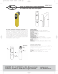
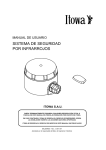
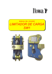
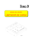
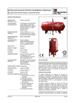
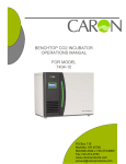
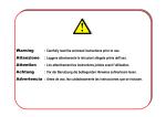
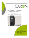
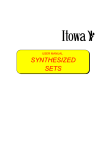
USER MANUAL
INFRARED SAFETY
SYSTEM
VA000960
ITOWA S.A.U.
IT IS FORBIDDEN TO FULLY OR PARTIALLY REPRODUCE THIS MANUAL, WITHOUT
THE PRIOR WRITTEN AUTHORISATION FROM ITOWA.
IN THE EVENT OF INFRINGEMENT, ITOWA RESERVES THE RIGHT TO TAKE THE
ACTION IT DEEMS NECESSARY, IN ACCORDANCE WITH CURRENT LAW.
ITOWA RESERVES THE RIGHT TO MODIFY THIS MANUAL WITHOUT PRIOR
NOTIFICATION
MALIMIRGB – Rev. 0 - M.E.C. – 25-10-05
Approved by Engineering Manager: J. Varela
INFRARED SYSTEM
USER MANUAL
1. INFRARED SAFETY SYSTEM
The infrared (IR) safety blocking system installed in a Itowa radio control equipment, enables it to limit
their range, so that the equipment is able to detect if a radio control transmitter is outside the area
defined as the working range, in which case, it deactivates operations (Range control) or does not
allow the equipment to start up (Start Control).
The system consists of an infrared transmitter (IR)1 (fig.1), installed by magnetic fastening in the
machine to be controlled, or at any point where it can cover the whole working range to be delimited,
and a small receiver (fig. 2) attached to the radio control transmitter.
Fig. 1. Infrared (IR) transmitter
Fig. 2. Infrared (IR) receiver
The equipment can use two different working modes, depending on the selected configuration of the
receiver:
-
Start Control: This mode only allows the Start-up operation of the radio frequency equipment
if it is within the action range of the infrared (IR) transmitter. However, once it is activated,
work can be continued normally outside the delimited range.
-
Range Control: This mode automatically activates the Emergency Stop if the radio
frequency equipment, with the small IR receiver installed, is outside the working range
delimited by the IR transmitter. Start-up and operation will only be possible within the working
range set by the IR transmitter.
The system consists of:
x
And infrared (IR) transmitter installed at a high point over the center of the delimited range
x
A small infrared (IR) receiver fitted in the radio control transmitter
This system is designed for easy installation in the majority of Itowa radio control models, including
those not currently manufactured.
1
IR: Infrared system
1
INFRARED SYSTEM
USER MANUAL
Similar to the radio control, this infrared (IR) blocking system incorporates a safety code, meaning that
it is highly reliable when several machines are operating at the same time as any possible
interferences are avoided.
The coverage area of the IR system depends on the height of the IR transmitter and how many are
installed, as if the working range covered by one single IR transmitter is considered insufficient, more
transmitters can be installed thereby increasing the working range. The number of transmitters will
depend on the size of the surface area to be covered.
Because of the optical nature of infrared rays, in order for the IR receiver to correctly acknowledge the
IR transmitter signal, the transmitter should be located at a visible point and free of obstacles,
otherwise the signal will not be received.
The operation of this equipment is limited to covered areas, where there is no direct sunlight, as this
significantly reduces the working range of the infrared system. The delimited area will depend on the
application.
2. INSTALLATION OF THE INFRARED TRANSMITTER
To connect the transmitter, first remove the front cover, by pressing and turning it anti-clockwise. Then
unscrew the two fastening screws of the circuit to access the backside, where the input binding post is
located.
Input feed should be 48/115/230Vac 50Hz and will be connected to the binding posts of the CN3
connector. To select the correct voltage, close one of the jumpers J7, J8 or J9, as shown in figure 3.
The default configuration is a voltage of 230Vac (J9).
1A FUSE
48Vac
115Vac
230Vac
CURRENT FEED
J7
J8
J9
FUS1
CN3
FASTENING
SCREW
RS485 PORT
A
B
FASTENING
SCREW
Fig.3. Connections of the IR transmitter
2
INFRARED SYSTEM
USER MANUAL
Once the transmitter has been connected, place the circuit back to its original position, using the two
screws, and click the cover back into place. Fully tighten the packing seal to maintain IP65 sealing.
The transmitter should be placed on a clean and flat metal surface, of a thickness not less than 4 mm.
for safey purposes, using the magnets included, and at a central point of the area to be covered (fig.
4)
OVERHEAD CRANE
IR TRANSMITTER
H
D
Fig. 4. Location of the IR transmitter
The diameter (D) of the working range of the transmitter is directly proportional to the height (H) at
which the transmitter is installed, so that the higher it is placed, the wider the area covered and vice
versa.
When installing the transmitter, bear in mind any possible obstacles, as the receiver must always be
visibly in line with the transmitter for correct operation.
The receiver must be installed in the radio frequency transmitter by technicians authorised by Itowa or
under their guidance, following the assembly instructions included in document INP0110 (Consult
technicians authorised by Itowa).
3. TECHNICAL SPECIFICATIONS
Transmitter
Receiver
Input: 48, 115, 230 Vac
Input: 7.2Vdc
Working temperature: -20 to +65ºC
(-4 to +149ºF)
Protection: IP65
3
Working temperature: -20 to +65ºC
(-4 to +149ºF)
Protection: IP65
Fastening: By Magnets
Fastening: Two screws for plastic (2,3 mm thread)
Measurements: 90 x 77mm
Measurements: 32 x 19 x 15mm
INFRARED SYSTEM
USER MANUAL
A. USEFUL ADRESSES
ITOWA S.A.U.
c/ Faraday, 159
08224 TERRASSA (BARCELONA)
Telf.: +34-93.733.98.50 Fax: +34-93.789.13.51
e-mail: [email protected]
http://www.itowa.com
4
DCLIMIRGB – Rev. 0
EC – DECLARATION OF CONFORMITY
The manufacturer:
ITOWA S.A
C/ Faraday, 159
E-08224 Terrassa
Barcelona, España
Tel.: +34 93 733 98 50
Fax: +34 93 789 13 51
According with the requirements of the R&TTE 1999/05/EC Annex III declares under
its responsibility that the radio remote control equipment designated as:
INFRARED SAFETY SYSTEM
Are in conformity with the following European Directives:
x
73/23/EC (February, 19th 1973): Electrical Equipment designed for use within
certain voltage limits
o
o
x
With the standard EN60215 (1989) concerning the safety requirements for radio
transmitting equipment.
With the standard EN 60215/A1 (1994) concerning the safety requirements for radio
remote transmitting equipment.
99/05/EC (March, 9th 1999): Radio and Telecommunications Terminal Equipment
(R&TTE).
o
o
With the standard EN 301 489-3 v1.4.1 concerning the electromagnetic compatibility
and Radio spectrum Matters (ERM); Electromagnetic Compatibility (EMC) standard for
radio equipment and services; Part 3: Specific conditions for Short-Range Devices
(SRD) operating on frequencies between 9 kHz and 40 GHz.
With the standard EN 300 220-3 v1.1.1 concerning the electromagnetic compatibility
and radio spectrum matters (ERM); Short Range Devices (SRD); Radio equipment to be
used in the 25 MHz to 1.000 MHz frequency range with power levels ranging up to 500
mW; Part 3 : Harmonized EN covering essential requirements under article 3.2 of the
R&TTE Directive.
Signatory :
Name : Ramón Faure
Function : Technical Manager
Place and date : Terrassa, March 07th 2005
Signature
PARTE DE INSTALACIÓN Y GARANTIA
Los equipos ITOWA cuentan con una garantía de 1 año. A causa de la naturaleza
del equipo que usted ha adquirido, el plazo de garantía empezará a contar a partir
de la salida del equipo de fábrica. La garantía de nuestros equipos comprende la
reposición o reparación de los elementos defectuosos detectados, incluida la mano
de obra precisa. La garantía será efectiva con los equipos dispuestos en los talleres
de nuestro Servicio Técnico.
La cobertura de la presente garantía se verá invalidada por cualquiera de los puntos
siguientes:
x Instalación incorrecta.
x Averías producidas por el cierre inadecuado.
x Manipulación del equipo por personal no autorizado.
x Uso inadecuado del equipo.
x Averías producidas por causas ajenas a nuestra responsabilidad como
sobretensiones, incendios, etc.
x Averías producidas por fenómenos naturales tales como rayos, seísmos,
inundaciones, etc.
Quedan excluidas de las presentes Condiciones de Garantía las pilas y/o baterías
suministradas con nuestros equipos o en forma de recambio.
MAPIGES – Rev. 2