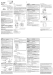
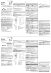
1
JY997D56801C Side B Side JAPANESE Side ENGLISH A B MELSEC iQ-F FX5-1PSU-5V Hardware Manual JY997D56801 1. Outline Revision C Date January 2015 When the FX5U CPU module internal power supplied from the FX5U CPU module is insufficient for powering the output modules or intelligent function modules, the FX51PSU-5V (extension power supply module) is available. In the FX5U CPU module, up to two units, the FX5-1PSU-5V or FX3U-1PSU-5V, can be used for one system. Connect extension module to the FX5-1PSU-5V according to the configuration specification limits described in the following manual. For details on installation and wiring, and system configuration with the FX5U CPU module including the FX5-1PSU-5V, refer to the following manual. MELSEC iQ-F FX5U User's Manual (Hardware) Check that the following product and items are included in the package: FX5-1PSU-5V extension power supply module Included Items Extension cable Dust proof protection sheet Hardware manual (This manual) 1.2 External Dimensions, Part Names and Terminal Layout 2-4.5 Mounting hole [3] This manual classifies the safety precautions into two categories: . [2] Indicates that incorrect handling may cause hazardous conditions, resulting in death or severe injury. Indicates that incorrect handling may cause hazardous conditions, resulting in minor or moderate injury or property damage. Depending on the circumstances, procedures indicated by cause severe injury. It is important to follow all precautions for personal safety. [1] [4] MELSEC iQ-F FX5U User's Manual (Hardware) [5] 8 (0.32") may also Make sure to cut off all phases of the power supply externally before attempting installation or wiring work. Failure to do so may cause electric shock or damage to the product. Use the product within the generic environment specifications described in the MELSEC iQ-F FX5U User's Manual (Hardware). Never use the product in areas with excessive dust, oily smoke, conductive dusts, corrosive gas (salt air, Cl 2 , H 2 S, SO 2 or NO 2 ), flammable gas, vibration or impacts, or expose it to high temperature, condensation, or rain and wind. If the product is used in such conditions, electric shock, fire, malfunctions, deterioration or damage may occur. [6] 83 (3.27") 50 (1.97") B Description JY997D55301 Explains FX5U CPU module specification details for I/O, wiring, installation, and maintenance. [7] The product connects on the right side of CPU module or extension module. For further information of installation arrangements, refer to the following manual. MELSEC iQ-F FX5U User's Manual (Hardware) The product is mounted by the following method. Direct mounting (with M4 screws) DIN rail mounting Compliance with EC directive (CE Marking) This note does not guarantee that an entire mechanical module produced in accordance with the contents of this note will comply with the standards. Compliance to EMC directive and LVD directive for the entire mechanical module should be checked by the user / manufacturer. For more information please consult with your local Mitsubishi Electric representative. 3. Wiring [6] [7] [8] [9] 5) Make sure to cut off all phases of the power supply externally before attempting installation or wiring work. Failure to do so may cause electric shock or damage to the product. Make sure to attach the terminal cover, provided as an accessory, before turning on the power or initiating operation after installation or wiring work. Failure to do so may cause electric shock. The temperature rating of the cable should be 80°C or more. Make sure to wire the screw terminal block in accordance with the following precautions. Failure to do so may cause electric shock, equipment failures, a short-circuit, wire breakage, malfunctions, or damage to the product. - The disposal size of the cable end should follow the dimensions described in the manual. - Tightening torque should follow the specifications in the manual. - Tighten the screws using a Phillips-head screwdriver No.2 (shaft diameter 6 mm (0.24") or less). Make sure that the screwdriver does not touch the partition part of the terminal block. For the power supply wiring, refer to the following manual. MELSEC iQ-F FX5U User's Manual (Hardware) Caution The FX5-1PSU-5V power supply should be turn ON simultaneously or before the CPU module. Before turning the power OFF, ensure the safety of the system and then simultaneously turn the CPU module, FX5-1PSU-5V, and other extension equipment (the special extension equipment is included) OFF. For details, refer to the following manual. MELSEC iQ-F FX5U User's Manual (Hardware) Grounding and power cables should be positioned to exit the module from above as shown in the following figure. Grounding cable and power cable 3.1 Applicable Cable and Terminal Tightening Torque The size of the terminal screws is M3. The end disposal of the cable shows below. Tighten the terminal to a torque of 0.5 to 0.8 Nm. Do not tighten terminal screws with a torque outside the above-mentioned range. Failure to do so may cause equipment failures or malfunctions. When one wire is connected to one terminal Crimp Terminal 3.2 (0.13") terminal screw Do not disassemble or modify the PLC. Doing so may cause fire, equipment failures, or malfunctions. For repair, contact your local Mitsubishi Electric representative. Do not drop the product or exert strong impact to it. Doing so may cause damage. The product is a precision instrument. During transportation, avoid impacts larger than those specified in the general specifications by using dedicated packaging boxes and shock-absorbing palettes. Failure to do so may cause failures in the product. After transportation, verify operation of the product and check for damage of the mounting part, etc. When connecting an input module to the FX5-1PSU-5V, supply the power of input circuit from the 24 V DC service power supply of the preceding CPU module or external power supply. Power supply wiring FX5-1PSU-5V L 6.2 mm (0.24") or less Terminal Class D grounding (Grounding resistance: 100 or less) 100 to 240 V AC Type No. FV1.25-B3A FV2-MS3 Certification Pressure Bonding Tool YA-1 (JST Mfg. Co., Ltd.) UL Listed When two wires are connected to one terminal 3.2 (0.13") Terminal screw 6.2 mm (0.24") or less Crimp terminal 6.3 mm (0.25") or more 3.2 (0.13") 6.2 mm (0.24") or less Terminal 6.3 mm (0.25") or more <Reference> Type No. FV1.25-B3A Certification UL Listed Pressure Bonding Tool Model name Applicability FX5U CPU module Ver. 1.000 or later (from first production) The items other than the following are equivalent to those of the CPU module. For the general specification, refer to the following manual. MELSEC iQ-F FX5U User's Manual (Hardware) Items 3.3 Grounding Ground the PLC as stated below. Perform class D grounding. (Grounding resistance: 100 or less) Ground the PLC independently if possible. If it cannot be grounded independently, ground it jointly as shown below. For details, refer to the following manual. MELSEC iQ-F FX5U User's Manual (Hardware) PLC Other equipment PLC Other equipment Shared grounding (Good condition) PLC Other equipment Common grounding (Not allowed) 4. Specification <Reference> 4.1 Applicable CPU module 4.2 General Specifications N Use ground wires thicker than AWG14 (2 mm2). Position the grounding point as close to the PLC as possible to decrease the length of the ground wire. 3.2 (0.13") JST Mfg. Co., Ltd. STARTUP AND MAINTENANCE PRECAUTIONS Please contact a certified electronic waste disposal company for the environmentally safe recycling and disposal of your device. Independent grounding (Best condition) 6.2 mm (0.24") or less Terminal Manufacturer Simultaneously turn on and off the power supplies of the CPU module and extension modules. TRANSPORTATION PRECAUTIONS Perform class D grounding (grounding resistance: 100 or less) of the grounding terminal on the CPU module and extension modules with a wire 2 mm2 or thicker. Do not use common grounding with heavy electrical systems (refer to Section 3.3). Connect the power supply wiring to the dedicated terminals described in this manual. If an AC power supply is connected to a DC input/output terminal or DC power supply terminal, the PLC will burn out. Make sure to observe the following precautions in order to prevent any damage to the machinery or accidents due to malfunction of the PLC caused by abnormal data written to the PLC due to the effects of noise: - Do not bundle the power line, control line and communication cables together with or lay them close to the main circuit, high-voltage line, load line or power line. As a guideline, lay the power line, control line and communication cables at least 100 mm (3.94") away from the main circuit, high-voltage line, load line or power line. - Ground the shield of the shielded wire or shielded cable at one point on the PLC. However, do not use common grounding with heavy electrical systems. JST Mfg. Co., Ltd. DESIGN PRECAUTIONS DISPOSAL PRECAUTIONS WIRING PRECAUTIONS Terminal Manufacturer Cautions on mounting and removing extension cables Make sure that the pullout tab of extension cables do not contact with the conductive parts of the module. When removing the extension cable, pull the pullout tab of the extension cable straight up. Direct mounting hole: 2 holes of 4.5 (0.18") (mounting screw: M4 screw) Top cover POWER LED (green) Name plate DIN rail mounting groove (DIN rail: DIN 46277, 35 mm (1.38") wide) DIN rail mounting hook Extension connector (for preceding module) Power supply terminal block Extension connector (for next module) 3.2 Power Supply Wiring WIRING PRECAUTIONS C 6) Lock the DIN rail mounting hook while pressing the product against the DIN rail. Keep a gap of approximately 2 mm (0.08") between the products. MASS (Weight): Approx. 0.3 kg (0.66 lbs) Outer painting color: Munsell 0.6B7.6/0.2 [1] [2] [3] [4] [5] FX5-1PSU-5V 3) Push out DIN rail mounting hook. 4) Fit the upper edge of the DIN rail mounting groove (below fig. C) onto the DIN rail. 5) Press the product against the DIN rail. 4) Applicable standards FX5-1PSU-5V comply with the EC Directive (EMC Directive, LVD Directive) and UL standards (UL, cUL). Further information can be found in the following manual. MELSEC iQ-F FX5U User's Manual (Hardware) Regarding the standards that relate to the CPU module, please refer to either the product catalog or consult with your local Mitsubishi Electric representative. B A Direct Mounting (with M4 screws) [9] How to obtain manuals For the necessary product manuals or documents, consult with your local Mitsubishi Electric representative. FX5-16E 2) Connect the extension cable (below fig. A) connected in the procedure 1) to the extension connector of FX5-1PSU-5V. Put the pullout tub (below fig. B) of the extension cable inside the top cover. 2.1 Arrangements The product can be mounted with M4 screws by using the direct mounting holes. Refer to the External Dimensions (Section 1.2) for the product’s mounting hole pitch information. Keep a gap of approximately 2 mm (0.08") between the products. For further information on direct installation, also refer to the following manual. MELSEC iQ-F FX5U User's Manual (Hardware) Terminal layout [8] Manual No. A Do not touch the conductive parts of the product directly. Doing so may cause device failures or malfunctions. When drilling screw holes or wiring, make sure that cutting and wiring debris do not enter the ventilation slits of the PLC. Failure to do so may cause fire, equipment failures or malfunctions. For the product supplied together with a dust proof sheet, the sheet should be affixed to the ventilation slits before the installation and wiring work to prevent foreign objects such as cutting and wiring debris. However, when the installation work is completed, make sure to remove the sheet to provide adequate ventilation. Failure to do so may cause fire, equipment failures or malfunctions. Install the product on a flat surface. If the mounting surface is rough, undue force will be applied to the PC board, thereby causing nonconformities. Install the product securely using a DIN rail or mounting screws. Work carefully when using a screwdriver such as installation of the product. Failure to do so may cause damage to the product or accidents. Connect the extension cables, peripheral device cables, input/output cables and battery connecting cable securely to their designated connectors. Loose connections may cause malfunctions. 2.2.1 Top cover is removed DIN Rail Mounting The product can be mounted on a DIN rail. 1) Connect the extension cable (below fig. A) to the CPU module, and extension module on the left. When connecting to the CPU module, FX5-32E, put the pullout tub of the extension cable inside the extension connector cover. When connecting to an extension module other than FX5-32E, pull the pullout tub (below fig. B) of the extension cable out to the right side of the top cover. For details on the extension cable connection, refer to the following manual. MELSEC iQ-F FX5U User's Manual (Hardware) INSTALLATION PRECAUTIONS 2.2 Mounting 16 (0.63") Associated Manual Manual name Unit: mm (inches) 90 (3.55") Safety Precautions (Read these precautions before use.) 80 (3.15")(Mounting hole pitch) Effective January 2015 Specifications are subject to change without notice. 2014 MITSUBISHI ELECTRIC CORPORATION 1.1 Incorporated Items Product 2.2.2 INSTALLATION PRECAUTIONS Manual Number This manual describes the part names, dimensions, installation, and specifications of the product. Before use, read this manual and manuals of relevant products fully to acquire proficiency in handling and operating the product. Make sure to learn all the product information, safety information, and precautions. And, store this manual in a safe place so that you can take it out and read it whenever necessary. Always forward it to the end user. Registration: Phillips is a registered trademark of Phillips Screw Company. The company name and the product name to be described in this manual are the registered trademarks or trademarks of each company. and 2. Installation Attention This product is designed for use in industrial applications. Note Manufactured by: Mitsubishi Electric Corporation 2-7-3 Marunouchi, Chiyoda-ku, Tokyo, 100-8310 Japan Manufactured at: Mitsubishi Electric Corporation Himeji Works 840 Chiyoda-machi, Himeji, Hyogo, 670-8677 Japan Authorized Representative in the European Community: Mitsubishi Electric Europe B.V. Gothaer Str. 8, 40880 Ratingen, German DESIGN PRECAUTIONS Make sure to set up the following safety circuits outside the PLC to ensure safe system operation even during external power supply problems or PLC failure. Otherwise, malfunctions may cause serious accidents. - Most importantly, set up the following: an emergency stop circuit, a protection circuit, an interlock circuit for opposite movements (such as normal vs. reverse rotation), and an interlock circuit (to prevent damage to the equipment at the upper and lower positioning limits). - Note that when the CPU module detects an error, such as a watchdog timer error, during self-diagnosis, all outputs are turned off. Also, when an error that cannot be detected by the CPU module occurs in an input/output control block, output control may be disabled. External circuits and mechanisms should be designed to ensure safe machinery operation in such a case. - Note that when an error occurs in a relay or transistor of an output circuit, the output might stay on or off. For output signals that may lead to serious accidents, external circuits and mechanisms should be designed to ensure safe machinery operation in such a case. Specifications Dielectric withstand 1.5 kV AC for 1 minute voltage Between power supply terminal (AC power) and 10 M or higher by 500 V DC ground terminal insulation resistance tester Insulation resistance 4.3 Power Supply Specifications Items Specifications Rated Supply voltage 100 to 240 V AC A l l o w a b l e s u p p l y v o l ta g e 85 to 264 V AC range Rated frequency 50/60 Hz Allowable instantaneous power failure time Operation can be continued upon occurrence of instantaneous power failure for 10 ms or less. Power fuse 250 V 3.15 A Time-lag Fuse In-rush current 25 A Max. 5 ms or less/ 100 V AC 50 A Max. 5 ms or less/ 200 V AC Power consumption 20 W Max. Output current*1 24 V DC 0.3 A*2 5 V DC 1.2 A*2 *1 Supply for extension modules connected after this module. *2 Maximum output current depends on the ambient temperature. For details, refer to the following manual. MELSEC iQ-F FX5U User's Manual (Hardware) Note for system configuration For further details on system configuration, refer to the following manual. MELSEC iQ-F FX5U User's Manual (Hardware) In the FX5U CPU module, up to two units, the FX5-1PSU-5V or FX3U-1PSU-5V, can be used for one system. The total of the consumed current of the extension module connected to FX51PSU-5V should be the output current capacity or less. However, when connecting an input module to the FX5-1PSU-5V, supply the power of input circuit from the 24 V DC service power supply of the preceding CPU module or external power supply. This manual confers no industrial property rights or any rights of any other kind, nor does it confer any patent licenses. Mitsubishi Electric Corporation cannot be held responsible for any problems involving industrial property rights which may occur as a result of using the contents noted in this manual. Warranty Mitsubishi will not be held liable for damage caused by factors found not to be the cause of Mitsubishi; opportunity loss or lost profits caused by faults in the Mitsubishi products; damage, secondary damage, accident compensation caused by special factors unpredictable by Mitsubishi; damages to products other than Mitsubishi products; and to other duties. For safe use This product has been manufactured as a general-purpose part for general industries, and has not been designed or manufactured to be incorporated in a device or system used in purposes related to human life. Before using the product for special purposes such as nuclear power, electric power, aerospace, medicine or passenger movement vehicles, consult with Mitsubishi Electric. This product has been manufactured under strict quality control. However when installing the product where major accidents or losses could occur if the product fails, install appropriate backup or failsafe functions in the system. YA-1 (JST Mfg. Co., Ltd.) HEAD OFFICE : TOKYO BUILDING, 2-7-3 MARUNOUCHI, CHIYODA-KU, TOKYO 100-8310, JAPAN JY997D56801C Side B Side JAPANESE Side ENGLISH A B MELSEC iQ-F FX5-1PSU-5V Hardware Manual JY997D56801 1. Outline Revision C Date January 2015 When the FX5U CPU module internal power supplied from the FX5U CPU module is insufficient for powering the output modules or intelligent function modules, the FX51PSU-5V (extension power supply module) is available. In the FX5U CPU module, up to two units, the FX5-1PSU-5V or FX3U-1PSU-5V, can be used for one system. Connect extension module to the FX5-1PSU-5V according to the configuration specification limits described in the following manual. For details on installation and wiring, and system configuration with the FX5U CPU module including the FX5-1PSU-5V, refer to the following manual. MELSEC iQ-F FX5U User's Manual (Hardware) Check that the following product and items are included in the package: FX5-1PSU-5V extension power supply module Included Items Extension cable Dust proof protection sheet Hardware manual (This manual) 1.2 External Dimensions, Part Names and Terminal Layout 2-4.5 Mounting hole [3] This manual classifies the safety precautions into two categories: . [2] Indicates that incorrect handling may cause hazardous conditions, resulting in death or severe injury. Indicates that incorrect handling may cause hazardous conditions, resulting in minor or moderate injury or property damage. Depending on the circumstances, procedures indicated by cause severe injury. It is important to follow all precautions for personal safety. [1] [4] MELSEC iQ-F FX5U User's Manual (Hardware) [5] 8 (0.32") may also Make sure to cut off all phases of the power supply externally before attempting installation or wiring work. Failure to do so may cause electric shock or damage to the product. Use the product within the generic environment specifications described in the MELSEC iQ-F FX5U User's Manual (Hardware). Never use the product in areas with excessive dust, oily smoke, conductive dusts, corrosive gas (salt air, Cl 2 , H 2 S, SO 2 or NO 2 ), flammable gas, vibration or impacts, or expose it to high temperature, condensation, or rain and wind. If the product is used in such conditions, electric shock, fire, malfunctions, deterioration or damage may occur. [6] 83 (3.27") 50 (1.97") B Description JY997D55301 Explains FX5U CPU module specification details for I/O, wiring, installation, and maintenance. [7] The product connects on the right side of CPU module or extension module. For further information of installation arrangements, refer to the following manual. MELSEC iQ-F FX5U User's Manual (Hardware) The product is mounted by the following method. Direct mounting (with M4 screws) DIN rail mounting Compliance with EC directive (CE Marking) This note does not guarantee that an entire mechanical module produced in accordance with the contents of this note will comply with the standards. Compliance to EMC directive and LVD directive for the entire mechanical module should be checked by the user / manufacturer. For more information please consult with your local Mitsubishi Electric representative. 3. Wiring [6] [7] [8] [9] 5) Make sure to cut off all phases of the power supply externally before attempting installation or wiring work. Failure to do so may cause electric shock or damage to the product. Make sure to attach the terminal cover, provided as an accessory, before turning on the power or initiating operation after installation or wiring work. Failure to do so may cause electric shock. The temperature rating of the cable should be 80°C or more. Make sure to wire the screw terminal block in accordance with the following precautions. Failure to do so may cause electric shock, equipment failures, a short-circuit, wire breakage, malfunctions, or damage to the product. - The disposal size of the cable end should follow the dimensions described in the manual. - Tightening torque should follow the specifications in the manual. - Tighten the screws using a Phillips-head screwdriver No.2 (shaft diameter 6 mm (0.24") or less). Make sure that the screwdriver does not touch the partition part of the terminal block. For the power supply wiring, refer to the following manual. MELSEC iQ-F FX5U User's Manual (Hardware) Caution The FX5-1PSU-5V power supply should be turn ON simultaneously or before the CPU module. Before turning the power OFF, ensure the safety of the system and then simultaneously turn the CPU module, FX5-1PSU-5V, and other extension equipment (the special extension equipment is included) OFF. For details, refer to the following manual. MELSEC iQ-F FX5U User's Manual (Hardware) Grounding and power cables should be positioned to exit the module from above as shown in the following figure. Grounding cable and power cable 3.1 Applicable Cable and Terminal Tightening Torque The size of the terminal screws is M3. The end disposal of the cable shows below. Tighten the terminal to a torque of 0.5 to 0.8 Nm. Do not tighten terminal screws with a torque outside the above-mentioned range. Failure to do so may cause equipment failures or malfunctions. When one wire is connected to one terminal Crimp Terminal 3.2 (0.13") terminal screw Do not disassemble or modify the PLC. Doing so may cause fire, equipment failures, or malfunctions. For repair, contact your local Mitsubishi Electric representative. Do not drop the product or exert strong impact to it. Doing so may cause damage. The product is a precision instrument. During transportation, avoid impacts larger than those specified in the general specifications by using dedicated packaging boxes and shock-absorbing palettes. Failure to do so may cause failures in the product. After transportation, verify operation of the product and check for damage of the mounting part, etc. When connecting an input module to the FX5-1PSU-5V, supply the power of input circuit from the 24 V DC service power supply of the preceding CPU module or external power supply. Power supply wiring FX5-1PSU-5V L 6.2 mm (0.24") or less Terminal Class D grounding (Grounding resistance: 100 or less) 100 to 240 V AC Type No. FV1.25-B3A FV2-MS3 Certification Pressure Bonding Tool YA-1 (JST Mfg. Co., Ltd.) UL Listed When two wires are connected to one terminal 3.2 (0.13") Terminal screw 6.2 mm (0.24") or less Crimp terminal 6.3 mm (0.25") or more 3.2 (0.13") 6.2 mm (0.24") or less Terminal 6.3 mm (0.25") or more <Reference> Type No. FV1.25-B3A Certification UL Listed Pressure Bonding Tool Model name Applicability FX5U CPU module Ver. 1.000 or later (from first production) The items other than the following are equivalent to those of the CPU module. For the general specification, refer to the following manual. MELSEC iQ-F FX5U User's Manual (Hardware) Items 3.3 Grounding Ground the PLC as stated below. Perform class D grounding. (Grounding resistance: 100 or less) Ground the PLC independently if possible. If it cannot be grounded independently, ground it jointly as shown below. For details, refer to the following manual. MELSEC iQ-F FX5U User's Manual (Hardware) PLC Other equipment PLC Other equipment Shared grounding (Good condition) PLC Other equipment Common grounding (Not allowed) 4. Specification <Reference> 4.1 Applicable CPU module 4.2 General Specifications N Use ground wires thicker than AWG14 (2 mm2). Position the grounding point as close to the PLC as possible to decrease the length of the ground wire. 3.2 (0.13") JST Mfg. Co., Ltd. STARTUP AND MAINTENANCE PRECAUTIONS Please contact a certified electronic waste disposal company for the environmentally safe recycling and disposal of your device. Independent grounding (Best condition) 6.2 mm (0.24") or less Terminal Manufacturer Simultaneously turn on and off the power supplies of the CPU module and extension modules. TRANSPORTATION PRECAUTIONS Perform class D grounding (grounding resistance: 100 or less) of the grounding terminal on the CPU module and extension modules with a wire 2 mm2 or thicker. Do not use common grounding with heavy electrical systems (refer to Section 3.3). Connect the power supply wiring to the dedicated terminals described in this manual. If an AC power supply is connected to a DC input/output terminal or DC power supply terminal, the PLC will burn out. Make sure to observe the following precautions in order to prevent any damage to the machinery or accidents due to malfunction of the PLC caused by abnormal data written to the PLC due to the effects of noise: - Do not bundle the power line, control line and communication cables together with or lay them close to the main circuit, high-voltage line, load line or power line. As a guideline, lay the power line, control line and communication cables at least 100 mm (3.94") away from the main circuit, high-voltage line, load line or power line. - Ground the shield of the shielded wire or shielded cable at one point on the PLC. However, do not use common grounding with heavy electrical systems. JST Mfg. Co., Ltd. DESIGN PRECAUTIONS DISPOSAL PRECAUTIONS WIRING PRECAUTIONS Terminal Manufacturer Cautions on mounting and removing extension cables Make sure that the pullout tab of extension cables do not contact with the conductive parts of the module. When removing the extension cable, pull the pullout tab of the extension cable straight up. Direct mounting hole: 2 holes of 4.5 (0.18") (mounting screw: M4 screw) Top cover POWER LED (green) Name plate DIN rail mounting groove (DIN rail: DIN 46277, 35 mm (1.38") wide) DIN rail mounting hook Extension connector (for preceding module) Power supply terminal block Extension connector (for next module) 3.2 Power Supply Wiring WIRING PRECAUTIONS C 6) Lock the DIN rail mounting hook while pressing the product against the DIN rail. Keep a gap of approximately 2 mm (0.08") between the products. MASS (Weight): Approx. 0.3 kg (0.66 lbs) Outer painting color: Munsell 0.6B7.6/0.2 [1] [2] [3] [4] [5] FX5-1PSU-5V 3) Push out DIN rail mounting hook. 4) Fit the upper edge of the DIN rail mounting groove (below fig. C) onto the DIN rail. 5) Press the product against the DIN rail. 4) Applicable standards FX5-1PSU-5V comply with the EC Directive (EMC Directive, LVD Directive) and UL standards (UL, cUL). Further information can be found in the following manual. MELSEC iQ-F FX5U User's Manual (Hardware) Regarding the standards that relate to the CPU module, please refer to either the product catalog or consult with your local Mitsubishi Electric representative. B A Direct Mounting (with M4 screws) [9] How to obtain manuals For the necessary product manuals or documents, consult with your local Mitsubishi Electric representative. FX5-16E 2) Connect the extension cable (below fig. A) connected in the procedure 1) to the extension connector of FX5-1PSU-5V. Put the pullout tub (below fig. B) of the extension cable inside the top cover. 2.1 Arrangements The product can be mounted with M4 screws by using the direct mounting holes. Refer to the External Dimensions (Section 1.2) for the product’s mounting hole pitch information. Keep a gap of approximately 2 mm (0.08") between the products. For further information on direct installation, also refer to the following manual. MELSEC iQ-F FX5U User's Manual (Hardware) Terminal layout [8] Manual No. A Do not touch the conductive parts of the product directly. Doing so may cause device failures or malfunctions. When drilling screw holes or wiring, make sure that cutting and wiring debris do not enter the ventilation slits of the PLC. Failure to do so may cause fire, equipment failures or malfunctions. For the product supplied together with a dust proof sheet, the sheet should be affixed to the ventilation slits before the installation and wiring work to prevent foreign objects such as cutting and wiring debris. However, when the installation work is completed, make sure to remove the sheet to provide adequate ventilation. Failure to do so may cause fire, equipment failures or malfunctions. Install the product on a flat surface. If the mounting surface is rough, undue force will be applied to the PC board, thereby causing nonconformities. Install the product securely using a DIN rail or mounting screws. Work carefully when using a screwdriver such as installation of the product. Failure to do so may cause damage to the product or accidents. Connect the extension cables, peripheral device cables, input/output cables and battery connecting cable securely to their designated connectors. Loose connections may cause malfunctions. 2.2.1 Top cover is removed DIN Rail Mounting The product can be mounted on a DIN rail. 1) Connect the extension cable (below fig. A) to the CPU module, and extension module on the left. When connecting to the CPU module, FX5-32E, put the pullout tub of the extension cable inside the extension connector cover. When connecting to an extension module other than FX5-32E, pull the pullout tub (below fig. B) of the extension cable out to the right side of the top cover. For details on the extension cable connection, refer to the following manual. MELSEC iQ-F FX5U User's Manual (Hardware) INSTALLATION PRECAUTIONS 2.2 Mounting 16 (0.63") Associated Manual Manual name Unit: mm (inches) 90 (3.55") Safety Precautions (Read these precautions before use.) 80 (3.15")(Mounting hole pitch) Effective January 2015 Specifications are subject to change without notice. 2014 MITSUBISHI ELECTRIC CORPORATION 1.1 Incorporated Items Product 2.2.2 INSTALLATION PRECAUTIONS Manual Number This manual describes the part names, dimensions, installation, and specifications of the product. Before use, read this manual and manuals of relevant products fully to acquire proficiency in handling and operating the product. Make sure to learn all the product information, safety information, and precautions. And, store this manual in a safe place so that you can take it out and read it whenever necessary. Always forward it to the end user. Registration: Phillips is a registered trademark of Phillips Screw Company. The company name and the product name to be described in this manual are the registered trademarks or trademarks of each company. and 2. Installation Attention This product is designed for use in industrial applications. Note Manufactured by: Mitsubishi Electric Corporation 2-7-3 Marunouchi, Chiyoda-ku, Tokyo, 100-8310 Japan Manufactured at: Mitsubishi Electric Corporation Himeji Works 840 Chiyoda-machi, Himeji, Hyogo, 670-8677 Japan Authorized Representative in the European Community: Mitsubishi Electric Europe B.V. Gothaer Str. 8, 40880 Ratingen, German DESIGN PRECAUTIONS Make sure to set up the following safety circuits outside the PLC to ensure safe system operation even during external power supply problems or PLC failure. Otherwise, malfunctions may cause serious accidents. - Most importantly, set up the following: an emergency stop circuit, a protection circuit, an interlock circuit for opposite movements (such as normal vs. reverse rotation), and an interlock circuit (to prevent damage to the equipment at the upper and lower positioning limits). - Note that when the CPU module detects an error, such as a watchdog timer error, during self-diagnosis, all outputs are turned off. Also, when an error that cannot be detected by the CPU module occurs in an input/output control block, output control may be disabled. External circuits and mechanisms should be designed to ensure safe machinery operation in such a case. - Note that when an error occurs in a relay or transistor of an output circuit, the output might stay on or off. For output signals that may lead to serious accidents, external circuits and mechanisms should be designed to ensure safe machinery operation in such a case. Specifications Dielectric withstand 1.5 kV AC for 1 minute voltage Between power supply terminal (AC power) and 10 M or higher by 500 V DC ground terminal insulation resistance tester Insulation resistance 4.3 Power Supply Specifications Items Specifications Rated Supply voltage 100 to 240 V AC A l l o w a b l e s u p p l y v o l ta g e 85 to 264 V AC range Rated frequency 50/60 Hz Allowable instantaneous power failure time Operation can be continued upon occurrence of instantaneous power failure for 10 ms or less. Power fuse 250 V 3.15 A Time-lag Fuse In-rush current 25 A Max. 5 ms or less/ 100 V AC 50 A Max. 5 ms or less/ 200 V AC Power consumption 20 W Max. Output current*1 24 V DC 0.3 A*2 5 V DC 1.2 A*2 *1 Supply for extension modules connected after this module. *2 Maximum output current depends on the ambient temperature. For details, refer to the following manual. MELSEC iQ-F FX5U User's Manual (Hardware) Note for system configuration For further details on system configuration, refer to the following manual. MELSEC iQ-F FX5U User's Manual (Hardware) In the FX5U CPU module, up to two units, the FX5-1PSU-5V or FX3U-1PSU-5V, can be used for one system. The total of the consumed current of the extension module connected to FX51PSU-5V should be the output current capacity or less. However, when connecting an input module to the FX5-1PSU-5V, supply the power of input circuit from the 24 V DC service power supply of the preceding CPU module or external power supply. This manual confers no industrial property rights or any rights of any other kind, nor does it confer any patent licenses. Mitsubishi Electric Corporation cannot be held responsible for any problems involving industrial property rights which may occur as a result of using the contents noted in this manual. Warranty Mitsubishi will not be held liable for damage caused by factors found not to be the cause of Mitsubishi; opportunity loss or lost profits caused by faults in the Mitsubishi products; damage, secondary damage, accident compensation caused by special factors unpredictable by Mitsubishi; damages to products other than Mitsubishi products; and to other duties. For safe use This product has been manufactured as a general-purpose part for general industries, and has not been designed or manufactured to be incorporated in a device or system used in purposes related to human life. Before using the product for special purposes such as nuclear power, electric power, aerospace, medicine or passenger movement vehicles, consult with Mitsubishi Electric. This product has been manufactured under strict quality control. However when installing the product where major accidents or losses could occur if the product fails, install appropriate backup or failsafe functions in the system. YA-1 (JST Mfg. Co., Ltd.) HEAD OFFICE : TOKYO BUILDING, 2-7-3 MARUNOUCHI, CHIYODA-KU, TOKYO 100-8310, JAPAN