1
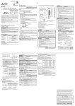
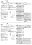
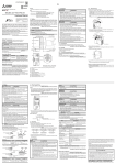
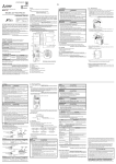
Side B ENGLISH A B MELSEC iQ-F FX5-4AD-ADP Hardware Manual Manual Number JY997D60201 Revision B Date January 2015 This manual describes the part names, dimensions, installation, and specifications of the product. Before use, read this manual and manuals of relevant products fully to acquire proficiency in handling and operating the product. Make sure to learn all the product information, safety information, and precautions. And, store this manual in a safe place so that you can take it out and read it whenever necessary. Always forward it to the end user. Registration: The company name and the product name to be described in this manual are the registered trademarks or trademarks of each company. Effective January 2015 Specifications are subject to change without notice. 2015 Mitsubishi Electric Corporation Safety Precaution (Read these precautions before use.) Applicable standards Installation in Enclosure Programmable controllers are open-type devices that must be installed and used within conductive control cabinets. Please use the programmable controller while installed within a conductive shielded control cabinet. Installation within a control cabinet greatly affects the safety of the system and aids in shielding noise from the programmable controller. Control cabinet - The control cabinet must be conductive. - Ground the control cabinet with the thickest possible grounding cable. - To ensure that there is electric contact between the control cabinet and its door, connect the cabinet and its doors with thick wires. - In order to suppress the leakage of radio waves, the control cabinet structure must have minimal openings. Also, wrap the cable holes with a shielding cover or other shielding devices. - The gap between the control cabinet and its door must be as small as possible by attaching EMI gaskets between them. Shielding cover Shielded cable . Indicates that incorrect handling may cause hazardous conditions, resulting in death or severe injury. Indicates that incorrect handling may cause hazardous conditions, resulting in minor or moderate injury or property damage. Depending on the circumstances, procedures indicated by cause severe injury. It is important to follow all precautions for personal safety. may also Associated Manuals Manual name Manual No. Description JY997D55301 Explains FX5U PLC specification details for I/O, wiring, installation, and maintenance. MELSEC iQ-F FX5UC User's Manual (Hardware) JY997D61301 Explains FX5UC PLC specification details for I/O, wiring, installation, and maintenance. MELSEC iQ-F FX5 User's Manual (Analog Control) JY997D60501 MELSEC iQ-F FX5U User's Manual (Hardware) Explains analog control. Unit: mm (inches) [10] [3] [5] [4] Terminal layout [6] [2] [7] [8] [1] Caution for EC Directive This manual classifies the safety precautions into two categories: and Wires*1 3. Wiring 1.2 External Dimensions, Part Names, and Terminal Layout FX5-4AD-ADP comply with the EC Directive (EMC Directive) and UL standards (UL, cUL). Further information can be found in the following manual. MELSEC iQ-F FX5U User's Manual (Hardware) MELSEC iQ-F FX5UC User's Manual (Hardware) Regarding the standards that relate to the CPU module, please refer to either the product catalog or consult with your nearest Mitsubishi product provider. Attention This product is designed for use in industrial applications. Note Manufactured by: Mitsubishi Electric Corporation 2-7-3 Marunouchi, Chiyoda-ku, Tokyo, 100-8310 Japan Manufactured at: Mitsubishi Electric Corporation Himeji Works 840 Chiyoda-machi, Himeji, Hyogo, 670-8677 Japan Authorized Representative in the European Community: Mitsubishi Electric Europe B.V. Gothaer Str. 8, 40880 Ratingen, Germany V1+ I1+ COM1 106 (4.18") JAPANESE Side 90 (3.55") Side 98 (3.86") (mounting hole pitch) JY997D60201B V2+ I2+ COM2 V3+ I3+ COM3 V4+ I4+ 8 (0.32") 74 (2.92") Special adapter connector cover is removed 15.1 (0.6") 15.1 (0.6") [9] COM4 17.6 (0.7") [11] DIN rail mounting groove (DIN rail: DIN46277, 35 mm (1.38") wide) Name plate Expansion adapter slide lock Expansion adapter connector cover Direct mounting hole: 2 holes of 4.5 (0.18") (mounting screw: M4 screw) PWR LED (green) Terminal block (European type terminal block) Expansion adapter connector DIN rail mounting hook Expansion adapter fixing hook Expansion adapter connector *1 These wires are used to improve the conductivity between the door and control cabinet. Cables - Make sure to use shielded cables as cables pulled out of the control cabinet. - Connect the shield such as shielded cables and shielding covers to the grounded control cabinet. It is possible that the accuracy temporarily fluctuates within ±10 %. Set the number of times of winding to "2 turns" within approximately 200 mm (7.87") from the terminal block of the analog cable on the FX5-4AD-ADP side, and attach a ferrite core. (Ferrite core used in our test: E04SR401938 manufactured by SEIWA ELECTRIC MFG. CO., LTD.) 1. Outline INSTALLATION PRECAUTIONS Make sure to cut off all phases of the power supply externally before attempting installation or wiring work. Failure to do so may cause electric shock or damage to the product. Use the product within the generic environment specifications described in the FX5 User's Manual (Hardware). Never use the product in areas with excessive dust, oily smoke, conductive dusts, corrosive gas (salt air, Cl 2 , H 2 S, SO 2 or NO 2 ), flammable gas, vibration or impacts, or expose it to high temperature, condensation, or rain and wind. If the product is used in such conditions, electric shock, fire, malfunctions, deterioration or damage may occur. INSTALLATION PRECAUTIONS Do not touch the conductive parts of the product directly. Doing so may cause device failures or malfunctions. When drilling screw holes or wiring, make sure cutting or wire debris does not enter the ventilation slits. Failure to do so may cause fire, equipment failures or malfunctions. Install the product on a flat surface. If the mounting surface is rough, undue force will be applied to the PC board, thereby causing nonconformities. Install the product securely using a DIN rail or mounting screws. Connect the expansion board and expansion adapter securely to their designated connectors. Loose connections may cause malfunctions. FX5-4AD-ADP analog input expansion adapter Included Items Hardware manual (This manual) How to obtain manuals For the necessary product manuals or documents, consult with your local Mitsubishi Electric representative. For the installation, refer to the following manual. MELSEC iQ-F FX5U User's Manual (Hardware) MELSEC iQ-F FX5UC User's Manual (Hardware) 4) Tool For tightening the terminal, use a commercially available small screwdriver having a straight form that is not widened toward the end as shown right. 4. Specifications With straight tip 0.4 mm (0.01") 2.5 mm (0.09") Note: If the diameter of screwdriver grip is too small, tightening torque may not be achieved. To achieve the appropriate tightening torque shown in the table above, use the following screwdriver or appropriate replacement (grip diameter: approximately 25 mm (0.98")). Manufacturer Model names Phoenix Contact GmbH & Co. KG SZS 0.4×2.5 5) Terminal block fixed screw tightening torque Tighten the screws within the range of 0.2 to 0.3 Nm. Do not tighten terminal screws exceeding with a torque outside the abovementioned range. Failure to do so may cause equipment failures or malfunctions. 3.2 Wiring of Analog Input For the terminal configuration, refer to Section 1.2 Using current input *1 4AD-ADP Terminal block 820 k V+ 250 *2 I+ 180 k COM CH *1 V+ 250 I+ COM 820 k CH 180 k V +, I+, COM, CH: represents the channel number. *1 Use 2-core shielded twisted pair cable for the analog input lines, and separate the analog input lines from other power lines or inductive lines. *2 Make sure to short-circuit the 'V+' and 'I+' terminals when current is input. (: input channel number) 3.3 Grounding Grounding should be performed as stated below. The grounding resistance should be 100 or less. Independent grounding should be performed for best results. When independent grounding is not performed, perform "shared grounding" of the following figure. For the details, refer to the following manual. MELSEC iQ-F FX5U User's Manual (Hardware) MELSEC iQ-F FX5UC User's Manual (Hardware) PLC Othere quipment Independent grounding (Best condition) PLC Othere quipment Shared grounding (Good condition) PLC Othere quipment Wire size Single wire, Strand wire Ferrules with insulating sleeve AWG22 to 20 (0.3 to 0.5 mm2) One wire Two wires AWG22 (0.3 AWG22 to 20 (0.3 to 0.5 mm2) mm2) - 2) Tightening torque Tighten the terminal screws with 0.20 Nm. Do not tighten the screws outside the specified torque. Failure to do so may cause equipment failures or malfunctions. 3) Wire end treatment Strip the coating of strand wire and twist the cable core before connecting it, or strip the coating of single wire before connecting it. When using a wire ferrule with an insulating sleeve, choose a wire with proper cable sheath referring to the above outside dimensions, otherwise the wire cannot be inserted easily. - Strand wire/single wire - Stick terminal with insulating sleeve Insulation sleeve 9 mm (0.36") Contact area (Crimp area) 8 mm (0.31") 2.6 mm (0.1") 14 mm (0.55") <Reference> Manufacturer Model Caulking tool Phoenix Contact GmbH & Co. KG AI 0.5-8 WH CRIMPFOX 6 CRIMPFOX 6T-F 4.4 Performance Specifications Item STARTUP AND MAINTENANCE PRECAUTIONS Specification Number of analog 4 points (4 channels) input points Do not disassemble or modify the PLC. Doing so may cause fire, equipment failures, or malfunctions. For repair, contact your local Mitsubishi Electric representative. Do not drop the product or exert strong impact to it. Doing so may cause damage. Analog input voltage -10 to +10 V DC (input resistance 1 M) Analog input current -20 to +20 mA DC (input resistance 250 ) Digital output value 14-bit binary value Analog input range DISPOSAL PRECAUTIONS Please contact a certified electronic waste disposal company for the environmentally safe recycling and disposal of your device. TRANSPORTATION PRECAUTIONS The product is a precision instrument. During transportation, avoid impacts larger than those specified in the general specifications by using dedicated packaging boxes and shock-absorbing palettes. Failure to do so may cause failures in the product. After transportation, verify operation of the product and check for damage of the mounting part, etc. Applicability FX5U CPU module Ver. 1.010 or later FX5UC CPU module Ver. 1.010 or later The items other than the following are equivalent to those of the CPU module. For general specifications, refer to the following manual. MELSEC iQ-F FX5U User's Manual (Hardware) MELSEC iQ-F FX5UC User's Manual (Hardware) Voltage Current Digital output value Resolution 0 to 10 V 0 to 16000 625 V 0 to 5 V 0 to 16000 312.5 V 1 to 5 V 0 to 12800 312.5 V -10 to +10V -8000 to +8000 1250 V 0 to 20 mA 0 to 16000 1.25 A 4 to 20 mA 0 to 12800 1.25 A -20 to +20 mA -8000 to +8000 2.5 A Accuracy (accuracy Ambient temperature 25±5: within ±0.1 % (±16 digit) for the full scale Ambient temperature 0 to 55: within ±0.2 % (±32 digit) digital output value) Maximum 450 s (The data will be updated at every scan time of the PLC.) Absolute maximum Voltage: ±15 V, Current: ±30 mA input Isolation method 4.2 General Specifications Item Input characteristics, resolution*1 Conversion speed 4.1 Applicable CPU module Model name Using voltage input European type terminal block No. of wire per terminal 1.1 Incorporated Items Product 3.1 Cable end treatment and tightening torque 1) Suitable wiring The FX5-4AD-ADP expansion adapter for analog input (hereinafter called 4AD-ADP) is a expansion adapter to add four analog input points. Verify that the following product and items are included in the package: When drilling screw holes or wiring, make sure cutting or wire debris does not enter the ventilation slits. Failure to do so may cause fire, equipment failures or malfunctions. Make sure to observe the following precautions in order to prevent any damage to the machinery or accidents due to malfunction of the PLC caused by abnormal data written to the PLC due to the effects of noise: 1) Do not bundle the power line or analog input/output cable together with or lay them close to the main circuit, high-voltage line, load line or power line. As a guideline, lay the power line, control line and communication cables at least 100 mm (3.94") away from the main circuit, high-voltage line, load line or power line. 2) Ground the shield of the analog input/output cable at one point on the signal receiving side. However, do not use common grounding with heavy electrical systems. 3.1.1 2. Installation EMI gasket Make sure to cut off all phases of the power supply externally before attempting installation or wiring work. Failure to do so may cause electric shock or damage to the product. Make sure to properly wire to the terminal block (European type) in accordance with the following precautions. Failure to do so may cause electric shock, equipment failures, a short-circuit, wire breakage, malfunctions, or damage to the product. - The disposal size of the cable end should follow the dimensions described in the manual. - Tightening torque should follow the specifications in the manual. - Twist the ends of stranded wires and make sure that there are no loose wires. - Do not solder-plate the electric wire ends. - Do not connect more than the specified number of wires or electric wires of unspecified size. - Affix the electric wires so that neither the terminal block nor the connected parts are directly stressed. WIRING PRECAUTIONS Weight: Approx. 0.1 kg (0.22 lbs) Outer painting color: Munsell 0.6B7.6/0.2 [1] [2] [3] [4] [5] [6] [7] [8] [9] [10] [11] WIRING PRECAUTIONS Between input terminal and PLC: Photocoupler Between input channels: Non-isolation Number of occupied 0 point (This number is not related to the maximum number of I/O points I/O points of the PLC.) *1 For the input conversion characteristic, refer to the following. MELSEC iQ-F FX5 User's Manual (Analog Control) Specification Dielectric withstand 500 V AC for one minute voltage Between all external terminals and ground 10 M or higher by 500 V DC terminal of CPU module Insulation resistance insulation resistance tester 4.3 Power Supply Specifications Item Specification 24 V DC 20 mA Internal electric supply Internal electric supply is carried out from 24 V DC power (A/D conversion circuit) supply of a CPU module. 5 V DC 10 mA Internal electric supply Internal electric supply is carried out from 5 V DC power (Interface) supply of a CPU module. Common grounding (Not allowed) The grounding wire size should be AWG 22 to 20 (0.3 to 0.5 mm2). The grounding point should be close to the PLC, and all grounding wire should be as short as possible. This manual confers no industrial property rights or any rights of any other kind, nor does it confer any patent licenses. Mitsubishi Electric Corporation cannot be held responsible for any problems involving industrial property rights which may occur as a result of using the contents noted in this manual. Warranty Mitsubishi will not be held liable for damage caused by factors found not to be the cause of Mitsubishi; opportunity loss or lost profits caused by faults in the Mitsubishi products; damage, secondary damage, accident compensation caused by special factors unpredictable by Mitsubishi; damages to products other than Mitsubishi products; and to other duties. For safe use This product has been manufactured as a general-purpose part for general industries, and has not been designed or manufactured to be incorporated in a device or system used in purposes related to human life. Before using the product for special purposes such as nuclear power, electric power, aerospace, medicine or passenger movement vehicles, consult with Mitsubishi Electric. This product has been manufactured under strict quality control. However when installing the product where major accidents or losses could occur if the product fails, install appropriate backup or failsafe functions in the system. HEAD OFFICE : TOKYO BUILDING, 2-7-3 MARUNOUCHI, CHIYODA-KU, TOKYO 100-8310, JAPAN Side B ENGLISH A B MELSEC iQ-F FX5-4AD-ADP Hardware Manual Manual Number JY997D60201 Revision B Date January 2015 This manual describes the part names, dimensions, installation, and specifications of the product. Before use, read this manual and manuals of relevant products fully to acquire proficiency in handling and operating the product. Make sure to learn all the product information, safety information, and precautions. And, store this manual in a safe place so that you can take it out and read it whenever necessary. Always forward it to the end user. Registration: The company name and the product name to be described in this manual are the registered trademarks or trademarks of each company. Effective January 2015 Specifications are subject to change without notice. 2015 Mitsubishi Electric Corporation Safety Precaution (Read these precautions before use.) Applicable standards Installation in Enclosure Programmable controllers are open-type devices that must be installed and used within conductive control cabinets. Please use the programmable controller while installed within a conductive shielded control cabinet. Installation within a control cabinet greatly affects the safety of the system and aids in shielding noise from the programmable controller. Control cabinet - The control cabinet must be conductive. - Ground the control cabinet with the thickest possible grounding cable. - To ensure that there is electric contact between the control cabinet and its door, connect the cabinet and its doors with thick wires. - In order to suppress the leakage of radio waves, the control cabinet structure must have minimal openings. Also, wrap the cable holes with a shielding cover or other shielding devices. - The gap between the control cabinet and its door must be as small as possible by attaching EMI gaskets between them. Shielding cover Shielded cable . Indicates that incorrect handling may cause hazardous conditions, resulting in death or severe injury. Indicates that incorrect handling may cause hazardous conditions, resulting in minor or moderate injury or property damage. Depending on the circumstances, procedures indicated by cause severe injury. It is important to follow all precautions for personal safety. may also Associated Manuals Manual name Manual No. Description JY997D55301 Explains FX5U PLC specification details for I/O, wiring, installation, and maintenance. MELSEC iQ-F FX5UC User's Manual (Hardware) JY997D61301 Explains FX5UC PLC specification details for I/O, wiring, installation, and maintenance. MELSEC iQ-F FX5 User's Manual (Analog Control) JY997D60501 MELSEC iQ-F FX5U User's Manual (Hardware) Explains analog control. Unit: mm (inches) [10] [3] [5] [4] Terminal layout [6] [2] [7] [8] [1] Caution for EC Directive This manual classifies the safety precautions into two categories: and Wires*1 3. Wiring 1.2 External Dimensions, Part Names, and Terminal Layout FX5-4AD-ADP comply with the EC Directive (EMC Directive) and UL standards (UL, cUL). Further information can be found in the following manual. MELSEC iQ-F FX5U User's Manual (Hardware) MELSEC iQ-F FX5UC User's Manual (Hardware) Regarding the standards that relate to the CPU module, please refer to either the product catalog or consult with your nearest Mitsubishi product provider. Attention This product is designed for use in industrial applications. Note Manufactured by: Mitsubishi Electric Corporation 2-7-3 Marunouchi, Chiyoda-ku, Tokyo, 100-8310 Japan Manufactured at: Mitsubishi Electric Corporation Himeji Works 840 Chiyoda-machi, Himeji, Hyogo, 670-8677 Japan Authorized Representative in the European Community: Mitsubishi Electric Europe B.V. Gothaer Str. 8, 40880 Ratingen, Germany V1+ I1+ COM1 106 (4.18") JAPANESE Side 90 (3.55") Side 98 (3.86") (mounting hole pitch) JY997D60201B V2+ I2+ COM2 V3+ I3+ COM3 V4+ I4+ 8 (0.32") 74 (2.92") Special adapter connector cover is removed 15.1 (0.6") 15.1 (0.6") [9] COM4 17.6 (0.7") [11] DIN rail mounting groove (DIN rail: DIN46277, 35 mm (1.38") wide) Name plate Expansion adapter slide lock Expansion adapter connector cover Direct mounting hole: 2 holes of 4.5 (0.18") (mounting screw: M4 screw) PWR LED (green) Terminal block (European type terminal block) Expansion adapter connector DIN rail mounting hook Expansion adapter fixing hook Expansion adapter connector *1 These wires are used to improve the conductivity between the door and control cabinet. Cables - Make sure to use shielded cables as cables pulled out of the control cabinet. - Connect the shield such as shielded cables and shielding covers to the grounded control cabinet. It is possible that the accuracy temporarily fluctuates within ±10 %. Set the number of times of winding to "2 turns" within approximately 200 mm (7.87") from the terminal block of the analog cable on the FX5-4AD-ADP side, and attach a ferrite core. (Ferrite core used in our test: E04SR401938 manufactured by SEIWA ELECTRIC MFG. CO., LTD.) 1. Outline INSTALLATION PRECAUTIONS Make sure to cut off all phases of the power supply externally before attempting installation or wiring work. Failure to do so may cause electric shock or damage to the product. Use the product within the generic environment specifications described in the FX5 User's Manual (Hardware). Never use the product in areas with excessive dust, oily smoke, conductive dusts, corrosive gas (salt air, Cl 2 , H 2 S, SO 2 or NO 2 ), flammable gas, vibration or impacts, or expose it to high temperature, condensation, or rain and wind. If the product is used in such conditions, electric shock, fire, malfunctions, deterioration or damage may occur. INSTALLATION PRECAUTIONS Do not touch the conductive parts of the product directly. Doing so may cause device failures or malfunctions. When drilling screw holes or wiring, make sure cutting or wire debris does not enter the ventilation slits. Failure to do so may cause fire, equipment failures or malfunctions. Install the product on a flat surface. If the mounting surface is rough, undue force will be applied to the PC board, thereby causing nonconformities. Install the product securely using a DIN rail or mounting screws. Connect the expansion board and expansion adapter securely to their designated connectors. Loose connections may cause malfunctions. FX5-4AD-ADP analog input expansion adapter Included Items Hardware manual (This manual) How to obtain manuals For the necessary product manuals or documents, consult with your local Mitsubishi Electric representative. For the installation, refer to the following manual. MELSEC iQ-F FX5U User's Manual (Hardware) MELSEC iQ-F FX5UC User's Manual (Hardware) 4) Tool For tightening the terminal, use a commercially available small screwdriver having a straight form that is not widened toward the end as shown right. 4. Specifications With straight tip 0.4 mm (0.01") 2.5 mm (0.09") Note: If the diameter of screwdriver grip is too small, tightening torque may not be achieved. To achieve the appropriate tightening torque shown in the table above, use the following screwdriver or appropriate replacement (grip diameter: approximately 25 mm (0.98")). Manufacturer Model names Phoenix Contact GmbH & Co. KG SZS 0.4×2.5 5) Terminal block fixed screw tightening torque Tighten the screws within the range of 0.2 to 0.3 Nm. Do not tighten terminal screws exceeding with a torque outside the abovementioned range. Failure to do so may cause equipment failures or malfunctions. 3.2 Wiring of Analog Input For the terminal configuration, refer to Section 1.2 Using current input *1 4AD-ADP Terminal block 820 k V+ 250 *2 I+ 180 k COM CH *1 V+ 250 I+ COM 820 k CH 180 k V +, I+, COM, CH: represents the channel number. *1 Use 2-core shielded twisted pair cable for the analog input lines, and separate the analog input lines from other power lines or inductive lines. *2 Make sure to short-circuit the 'V+' and 'I+' terminals when current is input. (: input channel number) 3.3 Grounding Grounding should be performed as stated below. The grounding resistance should be 100 or less. Independent grounding should be performed for best results. When independent grounding is not performed, perform "shared grounding" of the following figure. For the details, refer to the following manual. MELSEC iQ-F FX5U User's Manual (Hardware) MELSEC iQ-F FX5UC User's Manual (Hardware) PLC Othere quipment Independent grounding (Best condition) PLC Othere quipment Shared grounding (Good condition) PLC Othere quipment Wire size Single wire, Strand wire Ferrules with insulating sleeve AWG22 to 20 (0.3 to 0.5 mm2) One wire Two wires AWG22 (0.3 AWG22 to 20 (0.3 to 0.5 mm2) mm2) - 2) Tightening torque Tighten the terminal screws with 0.20 Nm. Do not tighten the screws outside the specified torque. Failure to do so may cause equipment failures or malfunctions. 3) Wire end treatment Strip the coating of strand wire and twist the cable core before connecting it, or strip the coating of single wire before connecting it. When using a wire ferrule with an insulating sleeve, choose a wire with proper cable sheath referring to the above outside dimensions, otherwise the wire cannot be inserted easily. - Strand wire/single wire - Stick terminal with insulating sleeve Insulation sleeve 9 mm (0.36") Contact area (Crimp area) 8 mm (0.31") 2.6 mm (0.1") 14 mm (0.55") <Reference> Manufacturer Model Caulking tool Phoenix Contact GmbH & Co. KG AI 0.5-8 WH CRIMPFOX 6 CRIMPFOX 6T-F 4.4 Performance Specifications Item STARTUP AND MAINTENANCE PRECAUTIONS Specification Number of analog 4 points (4 channels) input points Do not disassemble or modify the PLC. Doing so may cause fire, equipment failures, or malfunctions. For repair, contact your local Mitsubishi Electric representative. Do not drop the product or exert strong impact to it. Doing so may cause damage. Analog input voltage -10 to +10 V DC (input resistance 1 M) Analog input current -20 to +20 mA DC (input resistance 250 ) Digital output value 14-bit binary value Analog input range DISPOSAL PRECAUTIONS Please contact a certified electronic waste disposal company for the environmentally safe recycling and disposal of your device. TRANSPORTATION PRECAUTIONS The product is a precision instrument. During transportation, avoid impacts larger than those specified in the general specifications by using dedicated packaging boxes and shock-absorbing palettes. Failure to do so may cause failures in the product. After transportation, verify operation of the product and check for damage of the mounting part, etc. Applicability FX5U CPU module Ver. 1.010 or later FX5UC CPU module Ver. 1.010 or later The items other than the following are equivalent to those of the CPU module. For general specifications, refer to the following manual. MELSEC iQ-F FX5U User's Manual (Hardware) MELSEC iQ-F FX5UC User's Manual (Hardware) Voltage Current Digital output value Resolution 0 to 10 V 0 to 16000 625 V 0 to 5 V 0 to 16000 312.5 V 1 to 5 V 0 to 12800 312.5 V -10 to +10V -8000 to +8000 1250 V 0 to 20 mA 0 to 16000 1.25 A 4 to 20 mA 0 to 12800 1.25 A -20 to +20 mA -8000 to +8000 2.5 A Accuracy (accuracy Ambient temperature 25±5: within ±0.1 % (±16 digit) for the full scale Ambient temperature 0 to 55: within ±0.2 % (±32 digit) digital output value) Maximum 450 s (The data will be updated at every scan time of the PLC.) Absolute maximum Voltage: ±15 V, Current: ±30 mA input Isolation method 4.2 General Specifications Item Input characteristics, resolution*1 Conversion speed 4.1 Applicable CPU module Model name Using voltage input European type terminal block No. of wire per terminal 1.1 Incorporated Items Product 3.1 Cable end treatment and tightening torque 1) Suitable wiring The FX5-4AD-ADP expansion adapter for analog input (hereinafter called 4AD-ADP) is a expansion adapter to add four analog input points. Verify that the following product and items are included in the package: When drilling screw holes or wiring, make sure cutting or wire debris does not enter the ventilation slits. Failure to do so may cause fire, equipment failures or malfunctions. Make sure to observe the following precautions in order to prevent any damage to the machinery or accidents due to malfunction of the PLC caused by abnormal data written to the PLC due to the effects of noise: 1) Do not bundle the power line or analog input/output cable together with or lay them close to the main circuit, high-voltage line, load line or power line. As a guideline, lay the power line, control line and communication cables at least 100 mm (3.94") away from the main circuit, high-voltage line, load line or power line. 2) Ground the shield of the analog input/output cable at one point on the signal receiving side. However, do not use common grounding with heavy electrical systems. 3.1.1 2. Installation EMI gasket Make sure to cut off all phases of the power supply externally before attempting installation or wiring work. Failure to do so may cause electric shock or damage to the product. Make sure to properly wire to the terminal block (European type) in accordance with the following precautions. Failure to do so may cause electric shock, equipment failures, a short-circuit, wire breakage, malfunctions, or damage to the product. - The disposal size of the cable end should follow the dimensions described in the manual. - Tightening torque should follow the specifications in the manual. - Twist the ends of stranded wires and make sure that there are no loose wires. - Do not solder-plate the electric wire ends. - Do not connect more than the specified number of wires or electric wires of unspecified size. - Affix the electric wires so that neither the terminal block nor the connected parts are directly stressed. WIRING PRECAUTIONS Weight: Approx. 0.1 kg (0.22 lbs) Outer painting color: Munsell 0.6B7.6/0.2 [1] [2] [3] [4] [5] [6] [7] [8] [9] [10] [11] WIRING PRECAUTIONS Between input terminal and PLC: Photocoupler Between input channels: Non-isolation Number of occupied 0 point (This number is not related to the maximum number of I/O points I/O points of the PLC.) *1 For the input conversion characteristic, refer to the following. MELSEC iQ-F FX5 User's Manual (Analog Control) Specification Dielectric withstand 500 V AC for one minute voltage Between all external terminals and ground 10 M or higher by 500 V DC terminal of CPU module Insulation resistance insulation resistance tester 4.3 Power Supply Specifications Item Specification 24 V DC 20 mA Internal electric supply Internal electric supply is carried out from 24 V DC power (A/D conversion circuit) supply of a CPU module. 5 V DC 10 mA Internal electric supply Internal electric supply is carried out from 5 V DC power (Interface) supply of a CPU module. Common grounding (Not allowed) The grounding wire size should be AWG 22 to 20 (0.3 to 0.5 mm2). The grounding point should be close to the PLC, and all grounding wire should be as short as possible. This manual confers no industrial property rights or any rights of any other kind, nor does it confer any patent licenses. Mitsubishi Electric Corporation cannot be held responsible for any problems involving industrial property rights which may occur as a result of using the contents noted in this manual. Warranty Mitsubishi will not be held liable for damage caused by factors found not to be the cause of Mitsubishi; opportunity loss or lost profits caused by faults in the Mitsubishi products; damage, secondary damage, accident compensation caused by special factors unpredictable by Mitsubishi; damages to products other than Mitsubishi products; and to other duties. For safe use This product has been manufactured as a general-purpose part for general industries, and has not been designed or manufactured to be incorporated in a device or system used in purposes related to human life. Before using the product for special purposes such as nuclear power, electric power, aerospace, medicine or passenger movement vehicles, consult with Mitsubishi Electric. This product has been manufactured under strict quality control. However when installing the product where major accidents or losses could occur if the product fails, install appropriate backup or failsafe functions in the system. HEAD OFFICE : TOKYO BUILDING, 2-7-3 MARUNOUCHI, CHIYODA-KU, TOKYO 100-8310, JAPAN