1
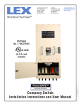
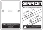
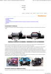
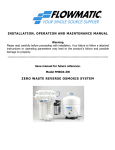
TABLE OF CONTENTS
Important Note
Page 3
Definition
Page 4
Preparation and General Information
Page 5
Important Concrete and Anchoring Information
Page 6
Installation and Basic Operation instruction
Page 8
Safety procedures
Page 10
Maintenance Schedule
Page 11
Troubleshooting
Page 13
Owners Responsibilities
Page 14
General information
(Fig 1 and Fig 2)
Page 15
Lifting Pads engaging area
(Fig 3)
Page 17
Prepare concrete
(Fig 4)
Page 18
Up-Right Overhead Assembly
Equalizing cable installation
(Fig 5)
Page 19
(Fig 6)
Page 20
(Fig 7)
Page 21
For Overhead Beam Type
Equalizing cable installation
For Floor Plate Type
Hydraulic system assembling
(Fig 8)
Page 22
For Floor Plate Type
Hydraulic system assembling (Fig 9)
Page 23
For Overhead Beam Type
Exploded Drawing
(Fig 11 – Fig 18)
Parts List for Floor Plate and Overhead Beam Type
2
Floor Plate/Overhead Style Lifts
Page 24
Page 32
IMPORTANT NOTES
● Do not install this lift on an asphalt surface.
● Do not install this lift on any surface other than concrete confirming to minimum
specifications.
● Do not install this lift over expansion joints or cracks. Check with an engineer.
● Do not install this lift on a second floor with a basement beneath without written
authorization from an engineer.
●
This lift is only as good as the floor you put it on. A good level floor is
recommended for proper lift installation and operation. Concrete should be a
minimum of 4” thick and 3,000psi tensile strength with steal or fiber mesh
reinforcement.
● The lift is intended to raise the entire body of the vehicle. Do not attempt to lift
only part of the vehicle. Improper use of this equipment could result in damage
to the lift, yourself or other property.
● The lift is intended to lift vehicles only. It is not designed to lift any person or
equipment containing people.
● Users of this equipment should be qualified, responsible and should follow the
operation and safety guidelines set forth in this manual.
● Improper installation can cause damage or injury. Manufacturer will not assume
liability for loss or damage of any kind, expressed or implied, resulting from
improper installation or use of this product. Read the installation and operation
manual in its entirety before attempting to install the lift.
3
Floor Plate/Overhead Style Lifts
DEFINITION
This lift is a 9000 lb. capacity, 2-Post Lift with a latch system. The
safety latch is in contact with the latch rack as the lift ascends and
drops into place. The safety latch engages in rack at 3” increments
beginning about 16”from the ground. The latch must be manually
disengaged for the lift to descend. The latch is released by raising the
latch up off the latch rack and pulling the release cable. Once the raise
button is pressed, the latch will automatically re-engage after
approximately 3” of travel. Heavy bearings and heavy-duty leaf chains
are used throughout the lift. The work is done with the heavy-duty
chain connected to a 2 1/2” cylinder, driven by a hydraulic pump
capable of providing 3,000psi.
Please read the Safety Procedures and Operation Instructions in this
manual before operating and installing the lift. Proper installation is
very important. To minimize the chance of making an error in
installation, please read this manual through carefully before
beginning installation. Check with building owner and/or an engineer
when applicable. The lift should be located on a relatively level floor 4”
thick and 3,000psi concrete sufficiently cured.
This is a vehicle lift installation/operation manual and no attempt is
made or implied herein to instruct the user in lifting methods particular
to an individual application. Rather, the contents of this manual are
intended as a basis for operation and maintenance of the unit as it
stands alone or as it is intended and anticipated to be used in
conjunction with other equipment.
Proper application of the equipment described herein is limited to the
parameters detailed in the specifications and the uses set forth in the
descriptive passages.
Met
r
i
cs
oc
k
et
sandopenwr
enc
hs
et
,1324mm
IMPORTANT CONCRETE AND ANCHORING INFORMATION
1. Concrete shall have compression strength of at least 3,000psi and a minimum thickness
of 4” in order to achieve a minimum anchor depth of 3 1/2”. If the top of the anchor exceeds
2” above the floor grade, you DO NOT have enough depth.
2. Use holes in column base plate as a guide before drilling the 3/4”diameter holes in the
concrete floor. Make sure the hole distance from the edge is not less than 6”. Hole depth
should be a minimum of 4”, it is recommended to drive through the 4” concrete, unless you
have a high water table.
3. CAUTION: DO NOT install on asphalt or other similar unstable surface. Columns are
supported only by anchoring into the floor.
4. Shim each column base until each column is plumb. If one column has to be elevated to
match the plane of the other column, then full-size base shim plates should be used
(Reference Shim Kit) torque anchors to 130 ft-lbs. Shim thickness MUST NOT exceed 3/8”
when using the 5 1/2” long anchor provided with the lift. Adjust the column extensions
plumb.
5. If anchors do not tighten to 130 ft-lbs installation torque, then replace concrete under
each column base with a 4’X4’X6” thick 3,000psi minimum concrete pad keyed under and
flush with the top of existing floor. Let concrete cure before installing lifts and anchors.
6
Floor Plate/Overhead Style Lifts
Dr
i
l
l
hol
et
odept
hof2”deepert
hanl
engt
hofanc
hororal
l
t
hewayt
hr
ought
he
c
onc
r
et
e.
ensur
et
hatt
hecol
umncanbepr
oper
l
yl
evel
ed.
2:
3:
4:
5:
6:
7:
8:
anant
i
wear32or46
19:
0:
LOWER THE LIFT
1. Raise the lift until the latch clears.
2. Pull both latch releases.
WARNING ALWAYS RELEASE BOTH SIDES
3. Press the lever at the power unit to lower the lift.
SAFETY PROCEDURES
z Never allow an unauthorized person to operate lift. Thoroughly train new employees
in the use and care of the lift.
z Caution-the power unit operates at high pressure.
z Remove passengers before raising vehicle.
z Prohibit unauthorized people from being in shop area while lift is in use.
z Total lift capacity is 9000lbs with 2500lbs per arm pad.
z Prior to lifting vehicle, walk around the lift and check for any objects that might
interfere with the operation of: lift, safety latches, tools, air hoses or shop equipment.
z When approaching the lift with a vehicle, center the vehicle between the columns so that
the tires will clear the swing arms easily. Slowly drive the vehicle up between the posts.
Have someone outside the vehicle guide the driver.
z Always lift vehicle using all four arms.
z Never use lift to raise one end or one side of vehicle.
z Raise vehicles about 3’ and check stability by rocking.
z Prior to lowering vehicle, walk around the lift and check for any objects that might
interfere with the operation of lift, safety latches, tools, air hoses or shop equipment. Swing
the arms out of the path and slowly drive the vehicle out. Have someone outside the vehicle
guide the driver.
ALWAYS LOCK THE LIFT BEFORE GOING UNDER THE VEHICLE.
NEVER ALLOW ANYONE TO GO UNDER THE LIFT WHEN RAISING OR
LOWERING.
MAINTENANCE SCHEDULE
The following periodic maintenance is the suggested minimum requirements and minimum
intervals of accumulated hours or monthly period, which ever comes sooner. If you hear a
noise or see any indication of impending failure – then cease operation immediately –
and inspect, correct and/or replace parts as required.
11
Floor Plate/Overhead Style Lifts
environment shorter interval may be required.
The following items should only be performed by a trained maintenance
expert.
z
z
z
z
z
z
z
Replace hydraulic hoses.
Replace chains and rollers.
Replace cables and sheaves.
Replace or rebuild air and hydraulic cylinders as required.
Replace or rebuild pumps/motors as required.
Check hydraulic and air cylinder rod and rod end (threads) for deformation or
damage.
Check cylinder mount for looseness and damage.
Relocating or changing components may cause problems. Each component in the system
must be compatible; an undersized or restricted line will cause a drop in pressure. All valve,
pump and hose connections should be sealed and/or capped until just prior to use. Air
hoses can be used to clean fittings and other components. However, the air supply must be
filtered and dry to prevent contamination. NOTE: Contamination is the most frequent cause
of malfunction or hydraulic equipment.
TROUBLE SHOOTING
1. Motor dose not run:
A. Breaker or fuse is blown.
B. Motor thermal overload tripped. Wait for overload to cool.
C. Faulty wiring connections. Call electrician.
D. Defective up button. Call electrician for checking.
2. Motor runs but will not raise:
A. A piece of trash is under check valve. Push the handle down and the up
button at the same time. Hold for 10-15 seconds. This should flush the system.
B. Check the clearance between the plunger valve of the lowering handle. There
should be 1/16 clearance.
C. Remove the check valve cover and clean ball and seat.
D. Oil level should be just under the vent cap port when the lift is down.
3. Oil blows out breather of power unit:
A. Oil reservoir overfilled.
B. Lift lowered too quickly while under a heavy load.
C. Return tube is loose or disconnected.
13
Floor Plate/Overhead Style Lifts
4. Motor hums and will not run:
A. Impeller fan cover is dented. Take off and straighten.
B. Faulty wiring. Call electrician
C. Bad capacitor. Call electrician
D. Low voltage. Call electrician
E. Lift overloaded. Reduce load.
5. Lift jerks going up and down: air in hydraulic system. Raise lift all the way to the top
and return to floor. Repeat 4-6 times. Do not let this overheat power unit.
6. Oil leaks:
A. Power unit: If the power unit leaks hydraulic oil around the tank mounting flange
then check the oil level in the tank. The level should be two inches below the flange
of the tank. Check with a screwdriver.
B. Rod end of cylinder: If the rod seal of the cylinder is leaking, then rebuild or
replace the cylinder.
C. Breather end of the cylinder: If the piston seal of the cylinder is leaking, then
rebuild or replace the cylinder.
7. Lift makes excessive noise:
A. Leg of the lift is dry and requires grease.
B. Cylinder pulley assembly or cable pulley assembly is not moving freely.
C. Pins or cylinder yoke may have excessive wear.
OWNER / EMPLOYER RESPONSIBILITIES
The Owner/Employer:
•
Shall establish procedures to periodically maintain, inspect and care for the lift in
accordance with the manufactures recommended procedures to ensure continued safe
operations.
•
Shall provide necessary lockout / tagouts of energy sources per ANSIZ244.1 –1982
before beginning any lift repairs.
•
Shall not modify the lift in any manner without prior written consent of the manufacturer.
•
Shall display the operating instructions supplied with the lift in a conspicuous location
in the lift area convenient to the operator.
•
Shall ensure that lift operators are instructed in the proper and safe use and operation of
the lift using the manufacturer’s instructions supplied with the lift.
14
Floor Plate/Overhead Style Lifts
INSTALLATION INSTRUCTION
For Floor Plate Lift
15
Floor Plate/Overhead Style Lifts
Fig 1
INSTALLATION INSTRUCTION
For Overhead Lift
16
Floor Plate/Overhead Style Lifts
Fig 2
INSTALLATION INSTRUCTION
Asymmetric Type
17
Floor Plate/Overhead Style Lifts
Fig 3
INSTALLATION INSTRUCTION
Prepare Concrete
18
Floor Plate/Overhead Style Lifts
Fig 4
INSTALLATION INSTRUCTION
Fig 5
Upright, Overhead Beam Assembly
19
Floor Plate/Overhead Style Lifts
INSTALLATION INSTRUCTION
Fig 6
Equalizing Cable Installation – Overhead Beam Type
20
Floor Plate/Overhead Style Lifts
INSTALLATION INSTRUCTION
Fig 7
Equalizing Cable Installation – Floor Plate Type
21
Floor Plate/Overhead Style Lifts
INSTALLATION INSTRUCTION
Fig 8
Hydraulic System Assembly – Floor Plate Type
22
Floor Plate/Overhead Style Lifts
INSTALLATION INSTRUCTION
Fig 9
Hydraulic System Assembly – Overhead Beam Type
23
Floor Plate/Overhead Style Lifts
24
Floor Plate/Overhead Style Lifts
25
Floor Plate/Overhead Style Lifts
IMPORTANT
POWER UNIT PRIMING PROCEDURE
THE PROBLEM: Power unit runs fine but will not pump any fluid.
Step 1 – Locate the check valve, the flush plug to the left of the lowering valve.
(See drawing below.)
Step 2 – Using an Allen wrench and shop towel – with shop towel in place to catch
fluid – loosen the check valve plug 2 ½ turns to allow it to leak.
Step 3 – Push the START button for one second, then release for three seconds.
Repeat these steps until unit starts pumping fluid.
Step 4 – Tighten the check valve plug.
YOUR POWER UNIT SHOULD BE PRIMED