1
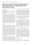
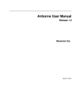
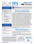
ReonixOne Alarm Notification Unit User Manual REONIX AUTOMATION INC. - CONFIDENTIAL AND PROPRIETARY NOTICE TO PERSONS RECEIVING THIS DOCUMENT AND/OR TECHNICAL INFORMATION THIS DOCUMENT, INCLUDING THE DRAWING AND INFORMATION CONTAINED THEREON, IS CONFIDENTIAL AND IS THE EXCLUSIVE PROPERTY OF REONIX AUTONATION INC, AND IS MERELY ON LOAN AND SUBJECT TO RECALL BY REONIX AT ANY TIME. BY TAKING POSSESSION OF THIS DOCUMENT, THE RECIPIENT ACKNOWLEDGES AND AGREES THAT THIS DOCUMENT CANNOT BE USED IN ANY MANNER ADVERSE TO THE INTERESTS OF REONIX, AND THAT NO PORTION OF THIS DOCUMENT MAY BE COPIED OR OTHERWISE REPRODUCED WITHOUT THE PRIOR WRITTEN CONSENT OF REONIX. IN THE CASE OF CONFLICTING CONTRACTUAL PROVISIONS, THIS NOTICE SHALL GOVERN THE STATUS OF THIS DOCUMENT. COPYRIGHT 2013 by Reonix Automation Inc. All rights reserved. 2 Table of Contents: 1. Introduction ............................................................................................................................. 5 2. Theory of Operation ................................................................................................................ 5 2.1 Principle of Operation ...................................................................................................... 5 2.1.1 Notification and Acknowledgement of Alarms by Email ..................................................... 5 2.1.2 Notification and Acknowledgement of Alarms by SMS (Text) messaging.......................... 5 2.1.3 Retrieving the Status of Current Alarms ............................................................................... 5 2.2 Escalation of Alarms ........................................................................................................ 5 2.3 Shifts................................................................................................................................. 6 3. Unit Specifications .................................................................................................................. 6 4. Hardware Connection: ............................................................................................................. 7 4.1 Wiring the digital alarm inputs......................................................................................... 7 4.2 Connecting Power ............................................................................................................ 7 4.2.1 Power using 24VDC ............................................................................................................. 7 4.2.2 Powering via POE (Power over Ethernet) ............................................................................ 7 4.3 5. 6. Configuration ........................................................................................................................... 8 5.1 Connection Configuration ................................................................................................ 8 5.2 Unit Configuration ........................................................................................................... 9 5.3 Digital Inputs Configuration .......................................................................................... 10 5.4 Modbus Configuration ................................................................................................... 11 5.5 Phonebook Configuration .............................................................................................. 12 5.6 Digital Input Alarm Configuration ................................................................................. 13 5.7 Modbus Alarm Configuration ........................................................................................ 14 5.8 Shifts Configuration ....................................................................................................... 15 5.9 Status Summary.............................................................................................................. 15 Troubleshooting ..................................................................................................................... 17 6.1 7. Connecting Computer to ReonixOne ............................................................................... 7 Resetting the ReonixOne................................................................................................ 17 6.1.1 Restoring the default IP address.......................................................................................... 17 6.1.2 Restoring the default parameters......................................................................................... 17 6.2 FAQ ................................................................................................................................ 17 6.3 Support Contacts ............................................................................................................ 18 Warranty Statement ............................................................................................................... 19 3 8. Feedback ................................................................................................................................ 21 Revision History: Revision 1.0 1.1 1.2 Date June 10, 2013 October 8, 2013 April 15, 2014 Description Initial Release Updated for firmware version 2.0 Updated for aluminum casing 4 1. Introduction The ReonixOne Alarm Notification Unit allows operators and maintenance personnel to be notified of an alarm condition at a remote site, either by email, or if used in conjunction with a cell modem, via text (SMS) messaging. The ReonixOne uses an Ethernet connection to connect through an internet connection that would be installed at the home or office; or through to cell modem. 2. Theory of Operation 2.1 Principle of Operation 2.1.1 Notification and Acknowledgement of Alarms by Email When an alarm condition is triggered, emails will be sent to the contacts listed. The email notifications are custom messages that are setup by the user via the web interface. Once an alarm message is received via email, the user can email a numeric code back to acknowledge the email. This numeric code is set up by the user, and is included in the email message. Once the alarm is acknowledged, no more notifications will be sent out until the alarm condition is triggered again. 2.1.2 Notification and Acknowledgement of Alarms by SMS (Text) messaging When an alarm condition is triggered, SMS messages will be sent to the contacts listed. The text notifications are custom messages that are setup by the user. Once an alarm message is received via text, the user can text a numeric code back to acknowledge the alarm. This numeric code is set up by the user, and is included in the text message. Once the alarm is acknowledged, no more notifications will be sent out until the alarm condition is triggered again. 2.1.3 Retrieving the Status of Digital Inputs To view the current status of alarms, the user either connect to the web browser and click the “Status” tab. 2.2 Escalation of Alarms When an alarm condition is triggered, a notification will be sent to the “First Call” contacts on the list. If no acknowledgement is received after a user configured time (“Escalation Delay”), the alarm will be sent to the “2nd Call” recipient(s), and so on. There are four groups of recipients that the notifications can be escalated through. 5 2.3 Shifts The shift feature allows off-duty personnel to stop receiving alarm notifications without deleting these personnel from the configuration. Each contact in the Phonebook can be assigned to a certain shift, which will be configured for a certain time of day, or certain weeks (ex. Two weeks on, two weeks off). When the personnel is on shift they will receive notifications. 3. Unit Specifications Physical Inputs: 8 digital inputs (24 VDC) Virtual Inputs: 5 Modbus TCP clients with up to 200 alarms Power: 12-24 VDC, optionally POE (Power Over Ethernet) Mounting: DIN rail mounting Dimensions: 4.75” x 2.125” x 3.125” Requires a cell modem or an Ethernet connection for call-out communication. The ReonixOne is housed in an aluminum case with plug-in terminal blocks for field wiring. Table 1 and Figure 1 show the connection points to the ReonixOne. Table 1: ReonixOne Wiring Connections WIRING CONNECTIONS 1. Digital Alarm 1 Input 2. Digital Alarm 2 Input 3. Digital Alarm 3 Input 4. Digital Alarm 4 Input 5. Digital Alarm 5 Input 6. Digital Alarm 6 Input 7. Digital Alarm 7 Input 6 8. Digital Alarm 8 Input 9. Dry Contact Terminal 1 10. Dry Contact Terminal 2 4. Hardware Connection: 4.1 Wiring the digital alarm inputs The digital alarms must be wired to the digital alarm input, as well as the common (COM). The notification for these inputs will be triggered when current is detected between the digital input terminal and the COM terminal. 4.2 Connecting Power 4.2.1 Power using 24VDC Wire 24 VDC to the terminal indicated on the top of the unit. 4.2.2 Powering via POE (Power over Ethernet) When using POE, connect the Ethernet cable to an Ethernet switch that supports POE. Note that not all Ethernet ports on an Ethernet switch supporting POE will have POE. In the case that POE is used, the digital inputs on the unit will still require power wired to them. 4.3 Connecting Computer to ReonixOne To connect using an Ethernet cable on the same network: 1. 2. 3. 4. 5. 6. Plug cable into computer to connect to network. Open Network and Sharing Center Select Local Area Connection Select Internet Protocol Version 4 (IPv4) Click Properties Enter an IP address that is the same network as the alarm unit. (eg. 192.168.1.23 if the unit is using the default IP address of 192.168.1.4). 7. Enter a subnet mask the matches the alarm unit (default is 255.255.255.0). 7 8. Click O.K. 9. Open a web browser and enter the IP address of the alarm unit. (default is 192.168.1.4) To connect through a cell modem, first connect to the cell modem, then open a web browser and type in the IP address of the alarm unit. See the specific manufacturer’s manual to connect to the cell modem. 5. Configuration 5.1 Connection Configuration Connect to the unit, either via Ethernet cable on the same network, or through a 3G modem. Enter the IP address of the unit into a web browser. The IP address is located on the side of the unit (default IP is 192.168.1.4). 8 5.2 Unit Configuration The first page on the web browser is the unit overview. Here the user can change the IP address, subnet mask, DNS server, default gateway, modem IP and modem type. The modem referred to here is the communication modem (ex. Microhard). The Email Setup refers to the email address that the notifications will be sent from. To get these setting, refer to the email account settings. 9 5.3 Digital Inputs Configuration In the above screen the user can select which of the hardwired digital inputs (located on the terminal strip) will be enabled or disabled. By disabling an input, the associated alarm and call-outs will be disabled as well. There is one digital output or dry contact. It is a normally open contact, meaning that when the output is de-energized or ReonixOne is powered down, the contact will be open. The user can select whether this output on (closed) or off (open). As an example, this output can be tied into another alarm system as a dry contact and left in the closed position. If the ReonixOne ever loses power, this contact will open or change state, notifying the other device that there has been an alarm failure. 10 5.4 Modbus Configuration There are five Modbus TCP slaves that can be configured. Each Slave requires the following information: 1. IP address: Address of the slave device 2. Unit ID: This by default is 255. Some devices require an address of 1. Alternatively, when using a Modbus Ethernet to RS-485 converter that is connected to multiple field devices, enter the Modbus Unit or Station ID that is configured in the field Modbus configuration. 3. Read Code: a. 1 refers to the Modbus #1 command. This will read coils or 0XXXX registers. b. 2 refers to the Modbus #2 command. This will read status inputs or 1XXXX registers. 4. # of Data: This is the number of coils or status inputs the alarm unit will read 5. Map to: This is the starting address of the first bit of data written into in the ReonixOne. The ReonixOne has space for 2000 coils to store data which has been retrieved from the Modbus slave devices. When assigning the map to numbers for multiple reads, make sure that the addresses do not overlap; otherwise, the data will be overwritten. Consult Reonix if you require more than 5 Modbus slave devices. 11 5.5 Phonebook Configuration The Phonebook allows the user to input individual contacts for call-out purposes. Contacts can be contacted via text, email, or both. Enter a valid phone number if the contact is to be contacted by text message. Note that in the current release; only North American phone numbers are supported. Enter a valid email address if the contact is to receive an email alert. The “Group” selection is configured in the Alarm configuration, where certain alarms assigned to groups, or certain groups are the first, second, third, or fourth group to receive the alarm during escalation scenarios. The “Shift” selection refers to the configuration on the Shift Change tab, where different “Shifts” will only receive alarms in the time slot that is set-up. Under “Current Contacts”, an entire list is displayed of all the contacts, with the option to remove contacts. Up to 100 contacts, and 8 groups can be configured. 12 5.6 Digital Input Alarm Configuration On the alarm configuration page the user can add alarms by selecting which digital input is to be used, a debounce time (delay time), and then the different groups to escalate to. The Alarm Acknowledge code is what the user will reply with via text or e-mail, to acknowledge the alarm. It will be included in the alarm message, There is a message box to enter the message to be delivered via text, or email (configured in the Phonebook). On this same page there is a similar configuration for the Modbus alarms. Note that each digital input may be associated with more than one alarm. This allows an alarm to go to one group which might be part of an escalating alarm scheme, and a second alarm may go to a contact who wants to be notified of an alarm, but who is not required to acknowledge the alarm. Up to 50 alarms can be configured for the 8 digital inputs. 13 5.7 Modbus Alarm Configuration On this same page there is a similar configuration for the Modbus alarms. Up to 200 alarms can be associated with the Modbus database points. See the Digital Alarm Configuration for detailed explanation of each feature. 14 5.8 Shifts Configuration Up to 4 shifts can be used. The default shift is none. When shifts are used, alarms will only call out to contacts which are currently on shift. This allows individuals who are not at work to not be notified of alarms. 5.9 Status Summary The status page allows the user to see if there are any alarm bits set, either for digital inputs, or for Modbus coils. 15 Products are activated by the manufacturer. If you receive a unit that has not been activated, please contact Reonix Automation to receive an activation code. Current shift displays the shift group that will receive alarm notifications. Shift configurations can be found under the “Shift Change” tab. 16 6. Troubleshooting 6.1 Resetting the ReonixOne 6.1.1 Restoring the default IP address The IP address of the ReonixOne can be reset to the default at any time by pressing the reset button, located on the front of the unit. The default address will again be 192.168.1.4. 6.1.2 Restoring the default parameters To clear the complete configuration of the ReonixOne and restore it to factory default settings, hold the reset button while cycling power. The default address will again be 192.168.1.4 and all the Phonebook entries and alarm points will be cleared. 6.2 FAQ Issue: I’ve installed the Unit as per the instructions but nothing happens. Check if the Power LED (2nd from the I/O connector) is on. If it is not, check the power terminals for 24VDC. If powered through a POE (Power over Ethernet) port, o make sure the ReonixOne in use has this option installed (Will be indicated on the label on the side of the box where the serial number is) o Makes sure the other end of the Ethernet cable plugged into the ReonixOne is plugged into an Ethernet Switch that supports POE. Note that on an Ethernet switch that supports POE, not all Ethernet ports support POE. Issue: The Unit will not program from the web browser Check the cable connections. If the connection is going through an Ethernet switch, check to ensure the switch has power. Confirm the I.P. Address of the unit. If connected through VPN, confirm that the tunnel is still enabled. Issue: The Unit does not text when an alarm occurs. Check connections to the Ethernet or modem. o Ensure that texting has been selected for the alarm. o Check the Phonebook to ensure the correct phone number has been added to the contact that is receiving the text notification. o Check that contact is part of the group that is configured for the alarm. o If the alarm is digital, ensure it has been enabled. Use the LED lights on the Unit to confirm that the digital signal is being sent. 17 o If the alarm is Modbus, ensure it has been enabled and properly mapped. Issue: The Unit does not send an e-mail when an alarm occurs. Check the connection to the Ethernet or modem. Ensure that e-mail has been selected for the alarm. Check the phonebook to ensure correct e-mail address has been added to the contact being called out to. Check the e-mail setup and ensure the proper e-mail server information has been entered. If the alarm is digital, ensure it has been enabled. Use the LED lights on the Unit to confirm that the digital signal is being sent. If the alarm is Modbus, ensure it has been enabled and properly mapped Issue: The Unit waits a long time before announcing the alarm. Check the alarm delay (debounce) setting for the alarm. The alarm will not call out until this timer has expired. Issue: The Unit continues to call out even after the alarms have been acknowledged. Check the field wiring to ensure a solid connection. If the input is “pulsing," instead of sending in a constant, clear signal, it can create false alarms. If the solution cannot be corrected with field wiring, increase the “Debounce Timer," on the Alarm Configuration page to try to prevent this problem. 6.3 Support Contacts More information can be found about us at our website www.reonix.com Reonix may be contacted by the following methods: Be Email: [email protected] By Telephone: 1-587-351-5554 By Mail: #205, 259 Midpark Way SE, Calgary, Alberta, Canada, T2X 1M2 18 7. Warranty Statement REONIX AUTOMATION INC. provides a one (1) year product warranty to cover any defects in materials and/or workmanship. If there is a defect or malfunction in the unit, it must be returned to REONIX for evaluation. REONIX will issue a Return Material Authorization (RMA) number upon notification of faulty unit. If REONIX finds the unit to be malfunctioning, it will be repaired or replaced at no charge. This warranty does not apply to defects resulting from mishandling, improper interfacing, operation outside of design limits, improper repair, consequential damages or unauthorized modifications. If evidence of tampering, or damage due to excessive corrosion, current, heat, moisture or vibration; improper specification, misapplication, misuse or consequential damages are apparent, this warranty will be deemed void. REONIX is pleased to offer suggestions on the use of its various products. However, REONIX neither assumes responsibility for any omissions or errors nor assumes liability for any damages that result from the use of its products in accordance with information provided by REONIX, either verbal or written. REONIX warrants only that the parts manufactured by it will be as specified and free of defects. REONIX MAKES NO OTHER WARRANTIES OR REPRESENTATIONS OF ANY KIND WHATSOEVER, EXPRESS OR IMPLIED, EXCEPT THAT OF TITLE, AND ALL IMPLIED WARRANTIES INCLUDING ANY WARRANTY OF MERCHANTABILITY AND FITNESS FOR A PARTICULAR PURPOSE ARE HEREBY DISCLAIMED. LIMITATION OF LIABILITY: The remedies of purchaser set for herein are exclusive, and the totally liability of REONIX with respect to this order, whether based on contract, warrant, negligence, indemnification, strict liability or otherwise, shall not exceed the purchase price of the component upon which liability is based. In no event shall REONIX be liable for consequential, incidental or special damages. CONDITIONS: Equipment sold by REONIX is not intended to be used, nor shall it be used: (1) as a “Basic Component” under 10 CFR 21 (NRC), used in or with any nuclear installation or activity; or (2) in medical applications or used on humans. Should ANY Product(s) be used in or with any nuclear installation or activity, medical application, used on humans, or misused in any way, REONIX assumes no responsibility as set forth in our basic WARRANTY/DISCLAIMER language, and additionally, purchaser with indemnify REONIX and hold REONIX harmless from any liability or damage whatsoever arising out of the use of the Product(s) in such a manner. RETURN REQUESTS/INQUIRIES Direct all warranty and repair requests/inquiries to the REONIX Customer Service Department. B EFORE RETURNING ANY PRODUCT(S) TO REONIX, PURCHAER MUST OBTAIN AN RETURN MATERIAL AUTHORIZATION (RMA) NUMBER FROM REONIX’S CUSTOMER SERVICE DEPARTMENT (IN ORDER TO AVOID PROCESSING DELAYS). The assigned RMA should then be marked on the outside of the return package and on any correspondence. The purchaser is responsible for shipping charges, freight, insurance and proper packaging to prevent breakage in transit. 19 FOR WARRANTY RETURNS, please have the following information available BEFORE contacting REONIX: Purchase Order number under which the product was PURCHASED, model and serial number of the product under warranty, and repair instructions and/or specific problems relative to the product. FOR NON-WARRANTY REPAIRS, consult REONIX for current repair charges. Have the following information available BEFORE contacting REONIX: Purchase Order number to cover the COST of the repair, model and serial number of the product, and repair instructions and/or specific problems relative to the product. 20 8. Feedback If you have any comments, suggestions or comments on the manual or product, please email us at [email protected] 21