1
Multi-Loader
User manual
VW3 A8 121
BBV48778
06/2014
www.schneider-electric.com
Contents
Important information __________________________________________________________________________________________ 4
Before you begin _____________________________________________________________________________________________ 5
Documentation structure _______________________________________________________________________________________ 6
Setup procedure _____________________________________________________________________________________________ 7
Introduction _________________________________________________________________________________________________ 8
Receipt of the Multi-Loader _____________________________________________________________________________________ 9
Presentation _____________________________________________________________________________________________ 10
Description of the HMI _____________________________________________________________________________________ 11
Description of the status Bar. ________________________________________________________________________________ 12
Connecting the Multi-Loader ___________________________________________________________________________________ 13
Connection to a PC _______________________________________________________________________________________ 13
Connection to a drive ______________________________________________________________________________________ 14
Connection to the graphic terminal (VW3A1101) _________________________________________________________________ 15
Compatibility ____________________________________________________________________________________________ 15
Configuration transfers ________________________________________________________________________________________ 16
Loading a configuration from a device and more. ________________________________________________________________ 16
Transferring the configuration to a device and more. (use Quick Store) _______________________________________________ 17
Multi-Loader menus __________________________________________________________________________________________ 18
Multi-Loader main menu ___________________________________________________________________________________ 18
Action: Store configuration from Multi-Loader to device ___________________________________________________________ 19
Action: Load configuration from device to Multi-Loader ____________________________________________________________ 20
Action: Update device using Multi-Loader ______________________________________________________________________ 21
Quick Store mode ________________________________________________________________________________________ 22
Supervision _____________________________________________________________________________________________ 23
Parameter settings: Batteries ________________________________________________________________________________ 24
Parameter settings: Diagnostics _____________________________________________________________________________ 25
Parameter settings: Password _______________________________________________________________________________ 27
Parameter settings: Display _________________________________________________________________________________ 28
Updating device application ____________________________________________________________________________________ 29
Compatibility ____________________________________________________________________________________________ 29
Transferring the device update file ____________________________________________________________________________ 30
Updating the Multi-Loader tool __________________________________________________________________________________ 31
Downloads _________________________________________________________________________________________________ 32
SoMove software _________________________________________________________________________________________ 32
Device update file ________________________________________________________________________________________ 32
Multi-Loader updated file ___________________________________________________________________________________ 32
Lists of faults codes __________________________________________________________________________________________ 33
BBV48778 06/2014
3
Important information
NOTICE
Read these instructions carefully, and look at the equipment to become familiar with the device before trying to install, operate, or maintain
it. The following special messages may appear throughout this documentation or on the equipment to warn of potential hazards or to call
attention to information that clarifies or simplifies a procedure
The addition of this symbol to a Danger or Warning safety label indicates that an electrical hazard exists, which will result in
personal injury if the instructions are not followed.
This is the safety alert symbol. It is used to alert you to potential personal injury hazards. Obey all safety messages that follow
this symbol to avoid possible injury or death.
DANGER
DANGER indicates an imminently hazardous situation, which, if not avoided, will result in death or serious injury.
WARNING
WARNING indicates a potentially hazardous situation, which, if not avoided, can result in death, serious injury or
equipment damage.
CAUTION
CAUTION indicates a potentially hazardous situation, which, if not avoided, can result in injury or equipment
damage.
NOTICE
NOTICE indicates a potentially hazardous situation, which, if not avoided, can result in equipment damage.
PLEASE NOTE
The word "drive" as used in this manual refers to the controller portion of the adjustable speed drive as defined by NEC.
Electrical equipment should be installed, operated, serviced, and maintained only by qualified personnel. No responsibility is assumed by Schneider Electric for any consequences arising out of the use of this product.
© 2013 Schneider Electric. All Rights Reserved.
4
BBV48778 06/2014
Before you begin
Read and understand these instructions before performing any procedure with this product.
DANGER
UNINTENDED EQUIPMENT OPERATION
• Read and understand this manual before installing or operating the Multi-loader.
• Any changes made to a device using the Multi-loader must be performed by qualified personnel.
• Read and understand the device manuals before you load or duplicate the Configuration from one device to another device.
• Ensure that you select the Configuration suitable for your application
• Before you load a new product firmware, read and understand the procedure "transferring the device update file" described on page 30.
Failure to follow these instructions will result in death or serious injury.
DANGER
HAZARD OF ELECTRIC SHOCK, EXPLOSION, OR ARC FLASH
• Only appropriately trained persons who are familiar with and understand the contents of this manual and all other pertinent
product documentation and who have received safety training to recognize and avoid hazards involved are authorized to work
on and with this product system. Installation, adjustment, repair and maintenance must be performed by qualified personnel.
• The system integrator is responsible for compliance with all local and national electrical code requirements as well as all other
applicable regulations with respect to grounding of all equipment.
• Many components of the product, including the printed circuit boards, operate with mains voltage. Do not touch. Use only
electrically insulated tools.
• Do not touch unshielded components or terminals with voltage present.
• Motors can generate voltage when the shaft is rotated. Prior to performing any type of work on the product system, block the
motor shaft to prevent rotation.
• AC voltage can couple voltage to unused conductors in the motor cable. Insulate both ends of unused conductors of the motor
cable.
• Do not short across the DC bus terminals or the DC bus capacitors or the braking resistor terminals.
• Before performing work on the product system:
- Disconnect all power, including external control power that may be present.
- Place a "Do Not Turn On" label on all power switches.
- Lock all power switches in the open position.
- Wait 15 minutes to allow the DC bus capacitors to discharge. The DC bus LED is not an indicator of the absence of DC bus
voltage that can exceed 800 Vdc.
Measure the voltage on the DC bus between the DC bus terminals using a properly rated voltmeter to verify that the voltage
is <42 Vdc.
- If the DC bus capacitors do not discharge properly, contact your local Schneider Electric representative.
• Install and close all covers before applying voltage.
Failure to follow these instructions will result in death or serious injury.
BBV48778 06/2014
5
Documentation structure
The following Multi-Loader documents are also available on www.schneider-electric.com.
Simplified manual
This manual is a simplified version of the user manual. It is delivered with the Multi-Loader.
User manual
This manual describes how to connect, configure and update the Multi-Loader.
6
BBV48778 06/2014
Setup procedure
1. Receive and inspect the Multi-Loader
Check that the reference printed on the label is the same as that on the
purchase order.
Remove the Multi-Loader from its packaging and check that it has not
been damaged in transit.
2. Connect the Multi-Loader (see page 13)
v To a PC
v To a device
3. Duplicate device configurations (see
page 16 and 17)
v Load a configuration onto the Multi-Loader
v Transfer a configuration to a device
v Transfer a configuration to several devices (Quick
Store)
4. Multi-Loader menus
(see page 18)
BBV48778 06/2014
7
Introduction
The Multi-Loader is a standalone tool for transferring configuration files to devices with their power on or off.
• The Multi-Loader is used to set device parameters by loading a configuration file onto the device(s). (Devices must have the same
reference. A consistency check is performed before the data transfer). On some devices the parameters can be set with them still in
their box or before they are powered up.
- This portable tool has been designed to load up to fifty devices a day and has a battery life of six days. However, this depends
on the transfer time, the size of the configuration files and other parameters associated with the settings for the Multi-Loader and
the connected devices.
- It can configure ten drives in less than five minutes.
- The Multi-Loader can provide the power supply for certain devices if they are turned off during the transfer.
• The Multi-Loader is also a firmware update tool.
- The "Password FW" mode can be used to help protect against incorrect operation by means of a password. See the "Password
FW" menu on page 27.
Duplicating or generating configuration files
A) Configuration duplicated
1) Transfer to one device
SoMove
2) Transfer to several
devices using Quick Store
B) Configuration generated
A) The device's configuration file is copied to the Multi-Loader's SD card. See the procedure on page 16.
B) The configuration file is generated by SoMove then transferred to the Multi-Loader's SD card. See the procedure on page 16.
1) The user selects and then transfers the configuration file from the Multi-Loader to the device. See the procedure on page 17.(Step
1 to 3)
2) Once the initial transfer is complete, the user can use Quick Store mode, which allows the Multi-Loader to load the same update file
on several devices in succession. (See page 17 Step 1 to 4)
Updating device firmware
1) Download the
device's firmware
update file
3) Transfer
1) The user downloads the device's specific update file.
2) The user transfers the device's firmware update file from the PC
to the Multi-Loader's SD card. See "Connection to a PC" on page 13.
3) The user selects and then transfers the product's firmware update
file from the Multi-Loader to the drive. See the procedure on page 30.
2) Transfer the update file
4) Transfer via Quick
Store
4) Once the initial transfer is completed, the user can use Quick
Store mode, which allows the Multi-Loader to load the same
updated file on several devices.
All representations of the ATV12 drive throughout this document are given by way of example only to symbolize a device. Please refer to
the device compatibility tables on pages 15 and 29.
All bold blue text in the manual (e.g. "Main menu / Action") corresponds to the messages displayed on the Multi-Loader screen.
8
BBV48778 06/2014
Receipt of the Multi-Loader
Product reference:
Check that the product reference printed on the label is the same as that on the delivery note. This should also correspond with the number
on the purchase order.
Contents of the Multi-Loader box (VW3A8121)
Check that the Multi-Loader box contains the following:
•
•
•
•
•
•
•
•
•
1 x Multi-Loader
4 x LR6 (AA) batteries
1 x SD card
1 x standard USB type A to Mini-B cable
1 x RJ45 (RJ45/RJ45) cable
1 x RJ45 female/female adapter (VW3A1105)
1 x carry case
1 x simplified manual (English and French)
1 x impact resistant cover
Available as an option
• Multi-Loader Cordset VW3A8126. (not compatible for ATV32 and LXM32)
BBV48778 06/2014
9
Receipt of the Multi-Loader
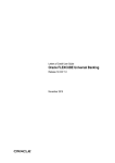
Presentation
65 mm / 2.6 In
181.51 mm / 7.26 In
27.4 mm / 1.09 In
Figure 1
Weight
250 grams (including batteries)
Data storage
One SD card is supplied with the Multi-Loader. Any standard SD card is compatible with the tool (not SDHC card except the model delivered
with the Multi-Loader).
Language
All menus are in English, French, German, Italian, Spanish, Chinese and Japanese.
Power supplies
Two options are available for powering the Multi-Loader:
1) With internal power supply:
• 4 x LR6 (AA) alkaline batteries (batteries included)
• NiMh rechargeable batteries (batteries and charger not included)
2) With external power supply :
• USB type A to Mini-B cable direct on the PC power supply
Battery life
Depending on the type of batteries used, the Multi-Loader can transfer up to 300 configuration files.
Power save feature
To prolong battery life, a standby function is activated within a programmable time delay; the Multi-Loader is reactivated by pressing the
ON/OFF button. (See the display parameters menu on page 28.)
Connection to a powered-up PC or device can also help conserve battery power, as the power supply from the connected device takes over
from the batteries.
10
BBV48778 06/2014
Receipt of the Multi-Loader
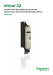
Description of the HMI
H
F
A
J
I
K
L
D
G
E
B
C
Figure 2
Letter
Description
Comments
Mini-B USB connector
The connection between the Multi-Loader (USB Mini-B type) and the PC
(USB type A) is via a 1 m (3.28 feet) USB type A to Mini-B cable.
RJ 45 connector
The connection between the Multi-Loader and the device is via a RJ45
cable to load and transfer configuration files or updated application
RJ11 connector with label cover
This connector is reserved for Schneider Electric product support.
SD card slot
The SD card receives and stores the files. One SD card is supplied with
the Multi-Loader.
E
Battery compartment
The Multi-Loader can take normal batteries or rechargeable batteries.
F
ON/OFF button
Press for 2 seconds to turn the tool on or off.
Quick Store key
Press this key to transfer data from the Multi-Loader to the device after
an initial transfer.
H
Screen
The screen comprises 2 lines of 16 characters. (see page 12)
I
ESC key
Returns to the previous screen.
J
ENT key
Confirms the parameter selection or cancels messages.
K
Up arrow key
For menu navigation.
L
Down arrow key
For menu navigation.
A
B
C
D
G
BBV48778 06/2014
11
Receipt of the Multi-Loader
Description of the status Bar.
The drawings below show names and functions of main parts display.
Status
Bar section 1
Status
Bar section 2
Status
Bar section 3
Status
Bar section 4
Line 1
Line 2
Status
Bar section 1
Status
Bar section 2
Status
Bar section 3
Multi-Loader is
connected to PC
Multi-Loader is
sending 5VDC to
device
Multi-Loader is
running on
Battery power
Battery full
Multi-Loader is
connected to
USB Power
supply
Multi-Loader is
sending 10VDC
to device
Multi-Loader is
running on USB
power
Battery 75%
Multi-Loader is
getting 10V input
from device
Multi-Loader is
running on RJ45
power
Battery 50%
Status
Bar section 4
Battery 25%
Battery low (less
then 20%)
12
BBV48778 06/2014
Connecting the Multi-Loader
This section describes the various ways of connecting the Multi-Loader.
Connection to a PC
There are two ways of storing files on the SD card:
- Insert the SD card in the Multi-Loader and connect the Multi-Loader to the PC with the standard USB type A to Mini-B cable (see
Figure 3 below) . The Multi-Loader is power supply by the PC.
Or
- Insert the SD card in the SD card reader on the PC (see Figure 4 below)
A
B
A: USB type A connector
B: USB Mini-B type connector
Figure 3
SD card reader
Figure 4
For both these methods, the SD card is recognized as an external storage device; no driver is required. The SD card operates in Windows
Explorer using the same copy/paste actions as any standard external storage medium.
Note:
• The PC must be on and operational before connecting the Multi-Loader to avoid an incorrect start up of the PC.
• The SD card must not be removed when the Multi-Loader is on and a transfer is in progress. Otherwise, data on the SD card may be
lost.
• The file name can have 32 characters and the special characters are forbidden.
• The following priority rules come into play when the Multi-Loader is connected to a PC:
- If no transfer is in progress between the Multi-Loader and the drive, the connection to the drive is ignored and the Multi-Loader is
detected by the PC.
- If a transfer is in progress between the Multi-Loader and the drive, the user has to wait until the transfer is complete. The MultiLoader should be reconnect to the pc for can be detected.
- If the Multi-Loader is connected to the PC without a SD card, it is necessary to disconnect the Multi-Loader before inserting SD
card to be recognized by the PC as an external storage device.
- If the Multi-Loader is connected to the PC without a SD card, it is power supply by the PC. Insert the SD card to be recognized
by the Multi-Loader, you can transfer configuration file.
Source of configuration files
There are two ways of managing configuration files:
- If a device's configuration is to be duplicated, it is copied to another device via the Multi-Loader. See "Loading a configuration
from device" on page 16 and "Configuration transfers" on page 17
- If the configuration file is generated by SoMove software, it must then be transferred to the Multi-Loader's SD card. See
"Downloads" on page 32 and "Connection to a PC" above.
BBV48778 06/2014
13
Connecting the Multi-Loader
Connection to a drive
There are three ways of transferring configuration files.
The drive is in its packaging
When the drive is off, the Multi-Loader is powered
Note: When the drive is in its box, the Multi-Loader Cordset option can be used for quicker and easier in-box connection (no locking tab on
the connector), thus speeding up the transfer and keeping the packaging intact.
The drive is mounted, wired, and powered-up
or
the drive is power on
When the drive is on, the Multi-Loader is powered by the drive via the RJ45 cable.
DANGER
HAZARD OF ELECTRIC SHOCK, EXPLOSION, OR ARC FLASH - EXPOSURE TO ENERGIZED PARTS
• Adhere to NFPA 70E guidelines when using the Multi-Loader.
• The Multi-Loader is to be used only by qualified personnel as defined in NFPA 70E
• Read and understand the manuals for the applicative drive before accessing the communication port of the drive.
• Ensure that the RJ45 cable is not damaged
Failure to follow these instructions will result in death or serious injury.
Schneider Electric recommends that all power from the drive and enclosures housing the drive is disconnected before performing this
procedure. If you choose not to follow this recommendation, you must adhere to NFPA 70E guidelines.
1. Remove all power from the drive and all enclosures housing the drive and wait 15 minutes to allow the DC bus of the drive to
discharge.
2. Insert the Multi-Loader's communication cable into the drive's RJ45 communication port. Refer to the drive's installation manual for
more information about how to perform this task.
3. Install and close all covers and doors before applying power to the drive. The drive must be powered on before performing an upload or
download.
4. Perform the desired transfer.
5. Upon completing the transfer, remove all power from the drive and the enclosures housing the drive and wait 15 minutes to allow the DC
bus of the drive to discharge.
6. Remove the Multi-Loader communication cable from the drive.
7. Install and close all covers and doors before reapplying power to the drive.
8. Confirm that the correct program is in the drive.
14
BBV48778 06/2014
Connecting the Multi-Loader
Connection to the graphic terminal (VW3A1101)
The Multi-Loader can be connected to the graphic terminal via its RJ45 female/female adapter (VW3A1105). This adapter is needed for
updating the graphic terminal.
Configuration transfers
Compatibility
The table below shows the devices that are compatible with the Multi-Loader. It shows which type of file can be transferred depending on
the state of the device.
The Multi-Loader can be used to:
• Transfer configuration ("*.cfg") files via the RJ45 cable supplied with the Multi-Loader.
Device
Power on
Power off
ATV303
ATV12
ATV212
ATV32
ATV312
LXM 32
LXM 32S
ATV31
ATV71
ATV61
Device compatible with the Multi-Loader tool
Note: When transferring files, devices must have the same reference. Any incompatibility will prompt an message "Wrong
reference Fault" and the transfer operation will not be done. (See the table of detected fault on page 25.)
BBV48778 06/2014
15
Configuration transfers
Loading a configuration from a device and more.
This procedure allows the user to retrieve a configuration file ("file.cfg") from a device and load it onto the Multi-Loader's SD card.
1
Main menu
Action
ENT
Action Config
MLD -> Device
Action Config
Device -> MLD
ENT
Device -> MLD
LoadFrmDxx?
ENT
Are there
more
99 files on the
card ?
ENT
Yes
No
Replace
LoadFrmDxx?
ENT
LoadFrmDxx?
<<<<
LoadFrmDxx?
<<<<<<<<
LoadFrmDxx?
<<<<<<<<<<<
<
Load config
Successful
STEP
2
Actions
1
•
•
•
•
•
Turn the Multi-Loader on using the ON/OFF button "F" (see page 11).
Connect the Multi-Loader to the device using the RJ45 cable (see page 14).
Press "ENT" when the screen displays Main menu / Action.
Select the Action Config / Device -> MLD menu using the arrow keys and press "ENT".
Device -> MLD / LoadFromDevice appears on the screen. Press ENT until the transfer starts.
2
• Load Config Successful: The configuration has been loaded successfully onto the Multi-Loader;
disconnect the RJ45 cable from the device. The device configuration file ("file.cfg") is now loaded onto the
Multi-Loader's SD card.
• Pressing "ENT" returns the user to the "Action Config" menu.
• For another loading configuration into the Multi-Loader, repeat the step 1 and step 2.
Note 1: The file will be stored in a folder (folder name is the first 5 letters of the device ID) kept in a directory called ‘LoadFrmDev’
located at root.
Note 2: Loading a configuration from an ATV61/71 device with option board could generate, a short time, the display of [Incorrect
config.] (CFF) fault on the device during the operation.
16
BBV48778 06/2014
Configuration transfers
Transferring the configuration to a device and more. (use Quick Store)
DANGER
UNINTENDED EQUIPMENT OPERATION
• Read and understand this manual before installing or operating the Multi-Loader.
• Any changes made to a device using the Multi-Loader must be performed by qualified personnel.
• Read and understand the device manuals before you load or duplicate the Configuration from one device to another device.
• Ensure that you select the Configuration suitable for your application
Failure to follow these instructions will result in death or serious injury.
This procedure allows the user to select the configuration file to be transferred to the device and use the Quick Store function (see page
22) to duplicate configurations.
The user must already have:
- Loaded the device configuration file (*.cfg) onto the Multi-Loader (see page 16)
Or
- Generated the configuration file using SoMove and loaded this file onto the Multi-Loader (filename1, filename 2, etc.)
Main menu
1
Action
ENT
Action Config
MLD -> Device
ENT
MLD -> Device
Filename1
ENT
Store config
Successful
2
MLD -> Device
Filename2
ENT
MLD -> Device
Filename N
Store config
Successful
Device 3
Store config
Successful
Device 4
Store config
Successful
Device n
ENT
FilenameX
>>>>
FilenameX
>>>>>>>>
3
ENT
4
FilenameX
>>>>>>>>>>>
>
Store config
Successful
STEP
Transfer
1
•
•
•
•
Turn the Multi-Loader on using the ON/OFF button "F" (see page 11).
Connect the Multi-Loader to the device using the RJ45 cable (see page 14).
Press "ENT" when the screen displays Main menu / Action.
Press "ENT" when the screen displays Action Config / MLD -> Device.
2
• Select the file to be transferred using the arrow keys and press "ENT" to start the transfer. If no device is connected,
a message (No device connected) appears on the screen (see page 25).
3
• The configuration has been transferred successfully from the Multi-Loader; disconnect the RJ45 cable from the device.
• Pressing "ENT" returns the user to the "Action Config / MLD -> Device" menu or see STEP 4 for the Quick store.
4
• Connect the Multi-Loader to the next device, then press the Quick Store key
• Store Config Successful: The configuration has been loaded successfully onto the second device; remove the RJ45
cable from the device. This action can be carried out as many times as necessary
Note : Storing a configuration to an ATV61/71 device with option board could generate, a short time, the display of [Incorrect config.]
(CFF) fault on the device during the operation.
BBV48778 06/2014
17
Multi-Loader menus
Multi-Loader main menu
On power-up, the Multi-Loader / Version "x.x" menu is displayed on the screen.
The diagram below shows the various menus that can be accessed from the Multi-Loader main menu.
Main menu / Action accesses the following functions:
- Load from Multi-Loader to device
- Load from device to Multi-Loader
- update software of device
Main menu / Device accesses the following information:
- Device type
- Device version
Main menu / Parameters accesses:
- Battery parameters
- Diagnostic parameters
- Password parameters
- Display parameters
Main menu / About MLD accesses:
- Multi-Loader version information
The Quick Store key "G" (see page 11) allows the user to transfer the most recent configuration file or update the device (see page 22).
ON
Page 22
Quick
Store
OFF
Multiloader
Version X.X
2s
ENT
ENT
ENT
Esc
Action Config
MLD -> Devic e
Main menu
About MLD
Main menu
Parameters
Main menu
Device
Main menu
Actio n
Page 19
ENT
Page 23
Parameters
Battery
Page 24
Esc
Build:AB,CD
dd-mm-yy,hh:mm
ENT
Esc
Esc
Action Config
Device -> MLD
ENT
Esc
Page 20
ENT
Parameters
Diagnostic
Page 25
ENT
Esc
Action Flash
Firmware
ENT
Esc
Page 21
Parameters
Password FW
Page 27
ENT
Parameters
Display
Page 28
ENT
Esc
Note : Quick Store mode is disabled when the Multi-Loader is loading files.
18
BBV48778 06/2014
Multi-Loader menus
Action: Store configuration from Multi-Loader to device
The diagram below shows the Action Config / MLD -> Device menu accessible from Main menu / Action.
Action Config / MLD -> Device: This menu accesses the transfer function for loading configurations from the Multi-Loader to the device.
Main
menu
Action Config
MLD -> Device
ENT
No device
connected
ENT
No
Device
connected?
Yes
ENT
No
SD card
Fault
SD card
readable?
Yes
Esc
Esc
MLD -> Device
Filename1
Esc
MLD -> Device
Filename2
ENT
MLD -> Device
FilenameN
ENT
The file is saved
for Quick Store
mode
ENT
Quick
Store
FilenameX
>>>>
FilenameX
>>>>>>>>
Transfer in
progress
FilenameX
>>>>>>>>>>>
>
Yes
Transfer
complete
No
Two types
of error message
Incomplete or
incorrect transfer
Store config
Successful
Page 22
BBV48778 06/2014
Yes
Quick Store
mode?
Store
config fault
Incorrect configuration
file for this device
Wrong reference
fault
No
19
Multi-Loader menus
Action: Load configuration from device to Multi-Loader
The diagram below shows the Action Config / Device -> MLD menu accessible from Main menu / Action.
Action Config / Device -> MLD: This menu accesses the transfer function for loading configurations from the device to the Multi-Loader.
Action Config
Device -> MLD
ENT
Device
connected?
No
No devic e
connected
No
SD card
Fault
ENT
Yes
ENT
SD card
readable?
Yes
Device -> MLD
LoadFromDevice
No
Esc
Are there more 99
files in the card ?
Yes
Replace
LoadFrmDxx?
Esc
ENT
LoadFrmDxx
<<<<
Transfer in
progress
LoadFrmDxx
<<<<<<<<
LoadFrmDxx
<<<<<<<<<<<
<
Transfer
complete?
No
Yes
Load config
Successful
ENT
Load
config fault
ENT
Note1: The file will be stored in a folder (folder name is the first 5 letters of the device ID) kept in a directory called ‘LoadFrmDev’ located
at root.
Note 2: The maximun number of configurations for each range are 99.
20
BBV48778 06/2014
Multi-Loader menus
Action: Update device using Multi-Loader
The diagram below shows the Action Flash / Firmware menu accessible from Main menu / Action.
Action Flash / Firmware: This menu accesses the transfer function for loading the software update file onto the device.
It is possible to protect the firmware update transfer. See the Parameters / Password FW menu on page 27.
An RJ45 cable is required for updating the device firmware (see the compatibility table on page 29). If a device is updated without being
turned on, the Multi-Loader provides the power supply.
Main
menu
Action Flash
Firmwar e
ENT
Device
connected?
No
ENT
No device
connected
Yes
Yes
Update
authorized?
No
Press and hold the
up or down arrow
key to define the
password more
quickly
Esc
Enter password
000
Enter password
NNN
Esc
ENT
ENT
Value between
[000 and 999]
Default value [000]
No
Password
correct?
Wrong
password
Yes
Update
authorized
No
SD card
readable?
Yes
Esc
Flash FW
Filename 1
SD card
Fault
Esc
Esc
Flash FW
Filename 2
ENT
Quick
Store
ENT
Flash FW
Filename N
ENT
Replace
Firmware?
ENT
Esc
ENT
The file is
saved for
Quick Store
mode
FilenameX
>>>>
FilenameX
>>>>>>>>
Transfer in
progress
FilenameX
>>>>>>>>>>>
>
Transfer
complete?
See lists of
faults codes
page 33
No
Yes
Page 22
Flash FW
Successful
Flash F W
Fault - 0X..
ENT
Yes
BBV48778 06/2014
ENT
Quick Store
mode?
No
21
Multi-Loader menus
Quick Store mode
This mode is used to transfer the latest configuration file (page 17) or latest device firmware updated file (page 30). (1)
The diagram below shows the Quick Store mode, which can be accessed after using either of the Action Config / MLD -> Device or Action
Flash / Firmware menus.
Device
connected?
No
No device
connected
No
SD card
Fault
ENT
Yes
SD card
readable?
ENT
Yes
File selected?
No
Yes
File
present on the
SD card?
No
ENT
Yes
Configuration
file
Page 19
Two file types
No file
selected
FW file
Page 21
Exit Quick Store
mode
Note 1: If the Multi-Loader is already loading a file, the Quick Store key is inactive.
Note 2: Quick Store mode can only be used after an initial transfer to a device has been completed.
(1) Files can only be transferred between devices with the same reference.
22
BBV48778 06/2014
Multi-Loader menus
Supervision
The diagram below shows the device main menu, accessible from Main menu / Device. This supervisory menu is used to check the
reference and version of the device connected to the Multi-Loader.
Device Type: This menu accesses the reference of the connected device.
Device SW version: This menu accesses the software version of the connected device.
Main menu
Device
Esc
ENT
Esc
Device
Type
Device
SW Version
ENT
Device
connected?
ENT
No
No
Yes
Yes
Esc
Device
connected?
Range
ATVXXXXXXXX
SW Version
Vxx.xx
Esc
ENT
ENT
No device
connected
ENT
BBV48778 06/2014
23
Multi-Loader menus
Parameter settings: Batteries
The diagram below shows the Parameters / Battery menu accessible from Main menu / Parameters.
Battery / Charge level: This menu displays the Multi-Loader charge level.
Battery / Alarm level: This menu is used to set message activation at a particular charge level. It warns the user about the battery charge
status according to the value set (see message fault detected on page 25).
Battery / Set battery type: This menu is used to select the type of battery used by the Multi-Loader (normal batteries or rechargeable
batteries). Users must ensure that the correct battery type is selected so that the Multi-Loader can accurately display the charge level. This
also affects message activation.
Parameters
Battery
ENT
Esc
Esc
Battery
Charge leve l
Esc
Battery
Alarm leve l
Battery
Set battery type
ENT
ENT
ENT
ENT
Charge leve l
႑႑႑႑႑႑႑႑႒ ႒
Press and hold the up
or down arrow key to
define this level value
more quickly
Value between
[0 and 50]%
Alarm leve l
20%
Alarm leve l
NN%
ENT
Save this level
24
Esc
Esc
ENT
Set battery type
Normal
Set battery type
Rechargeable
Esc
Esc
ENT
Save the battery type
BBV48778 06/2014
Multi-Loader menus
Parameter settings: Diagnostics
The diagram below shows the Parameters / Diagnostic menu accessible from Main menu / Parameters.
Diagnostic / Fault History: This menu accesses the detected fault history.
Diagnostic / Clear Faults: This menu is used to clear the detected fault history
Parameters
Diagnostic
ENT
Esc
Esc
Diagnostic
Fault History
Diagnostic
Clear faults
ENT
Fault History
fault 1
ENT
Esc
Are you sure to
clear faults?
Esc
List of cleared
faults codes
ENT
Fault History
fault 2
Fault History
fault 3
Esc
See the table of
faults codes below
Esc
Clear faults
History done
ENT
DANGER
UNINTENDED EQUIPMENT OPERATION DUE TO TRANSFER INTERRUPTION
If an interruption occurs during the transfer of configuration to the device :
• Identify and correct the cause of interruption.
• Repeat the transfer.
Failure to follow these instructions will result in death or serious injury.
Multi-Loader display
Alert: Low
Battery Level
Switch off
Low battery
Store
config fault
Wrong reference
Fault
BBV48778 06/2014
Probable cause
The battery charge is low. The appearance of this
message depends on the charge level defined by
the user. (See setting the detection page 24.)
The battery charge is too low. The Multi-Loader will
turn off.
Remedy
-
-
Replace the batteries immediately. No more
transfers can be made.
-
Check the RJ45 cable and both of its
connectors. Make sure the connection is
secure for the duration of the transfer. Restart
the transfer operation.
-
Check that the configuration file is compatible
with the device to be configured.
Incomplete or incorrect transfer to the device
Bad transfer to the device; the configuration file
selected is not compatible with the destination
device.
Make sure you have a set of replacement
batteries to hand, as the current set have little
life left.
Remains not enough time of use.
25
Multi-Loader menus
Parameter settings: Diagnostics
Multi-Loader display
Load
config fault
Incomplete or incorrect transfer from the MultiLoader to the device
Flash FW
Fault
Incomplete or incorrect device update
No device
connected
The device is not connected or is incorrectly
connected.
No file
selected
No configuration file is selected.
There is no file present on the SD card.
Wrong
password
The password is incorrect.
SD card
fault
The card is not recognized.
FLSH MSD
Error
26
Probable cause
Incomplete or incorrect Multi-Loader update
Remedy
-
Check the RJ45 cable and both of its
connectors. Restart the transfer operation.
-
Check the RJ45 cable and both of its
connectors. Make sure the connection is
secure for the duration of the transfer. Restart
the transfer operation.
-
Check the RJ45 cable and both of its
connectors. Make sure the connection is
secure for the duration of the transfer.
Connect the RJ45 cable.
-
Select a file to transfer.
Follow the procedure for loading configuration
files described on page 16.
-
Enter the password correctly (the default
password is [000]).
-
Check that the SD card is inserted correctly.
Check that the SD card is formatted correctly.
-
Check that the SD card is inserted correctly.
Check the version files for updating MultiLoader. See page 31
BBV48778 06/2014
Multi-Loader menus
Parameter settings: Password
Parameters / Password FW
The diagram below shows the Parameters / Password FW menu accessible from Main menu / Parameters.
Parameters / Password FW: This code helps protect the device from accidental firmware updating.
Parameters
Password FW
ENT
No
Is there a
password?
Yes
Old password
000
Old password
NNN
Esc
Press and hold the
up or down arrow
key to define the
password more
quickly
ENT
ENT
Wrong
password
Esc
No
Value between
[000 and 999]
Default value
[000]
Is the
password
correct?
Yes
Esc
New password
000
Esc
New password
NNN
Press and hold the
up or down arrow
key to define the
password more
quickly
ENT
Password saved,
firmware updating
protected
BBV48778 06/2014
27
Multi-Loader menus
Parameter settings: Display
The diagram below shows the Parameters / Display menu accessible from Main menu / Parameters.
Display / Contrast: This menu is used to set the display screen contrast.
Display / Backlight: This menu is used to set the display screen backlight.
Display / Sleep mode: This menu is used to set the Multi-Loader's sleep mode.
Display / Language: This menu accesses the language selection for the Multi-Loader interface.
Parameters
Display
ENT
Esc
Esc
Esc
Display
Contrast
Display
Backlight
Display
Sleep mode
ENT
ENT
ENT
Esc
Display
Language
ENT
Esc
Set contrast
50
Set contrast
NN
ENT
Saves the
contrast value
Press and hold the
up or down arrow
key to define the
contrast value more
quickly
Value between
[0 and 100]
Esc
Esc
ENT
Esc
Set backlight
ON
Esc
Set sleep mode
05 min
Esc
Set backlight
OFF
ENT
Saves the
backlight value
Set sleep mode
NN min
ENT
Esc
ENT
Language
English
Esc
Esc
ENT
Language
日本語
ENT
Saves the sleep
mode value
Press and hold the
up or down arrow
key to define the
sleep mode value
more quickly
Value between
[1 and 60] min
ENT
ENT
ENT
Language
Français
Language
Italiano
Language
Deutch
Language
Español
Esc
Esc
Esc
Esc
ENT
Save language
28
BBV48778 06/2014
Updating device application
Compatibility
DANGER
UNINTENDED EQUIPMENT OPERATION
• Read and understand this manual before installing or operating the Multi-Loader.
• Any changes made to a device using the Multi-Loader must be performed by qualified personnel.
• Before you load a new product firmware, read and understand the procedure "transferring the device update file" describes page 30.
• Ensure that you select the Firmware suitable for your application
Failure to follow these instructions will result in death or serious injury.
The Multi-Loader can be used to update a device's firmware ("*.fw") file via the RJ45 cable provided in the box.
The table below shows the devices that are compatible with the Multi-Loader. It shows which type of file can be transferred depending on
the state of the device.
Device
Power off
Graphic terminal
(VW3A1101)
ATV303
ATV12
ATV32
Lexium 32
Lexium 32S
Device compatible with the Multi-Loader tool
Note 1: The update file must be compatible with the device. Any incompatibility will prompt a message "Wrong reference Fault" and the
transfer operation will not be done. (See table on page 25.)
Note 2: When updating device firmware, you must ensure that all downloaded files are copied to the Multi-Loader's SD card ("*.fw" file and
executable file).
Note 3: Ensure that you update the product device label and the keypad label after updating device application.
BBV48778 06/2014
29
Procedure
Transferring the device update file
This procedure describes how to select the device update file. The user can then use Quick Store mode for the rest of the operation (see
page 22). The user must already have:
- Downloaded the update file from www.schneider-electric.com (see page 31)
AND
- Transferred the file to the Multi-Loader (see page 13, Connection to a PC)
Main menu
Action
1
ENT
Action Config
MLD -> Device
Action Flash
Firmwar e
ENT
Flash FW
Filename 1
ENT
Flash FW
Successful
Device 1
Flash FW
Successful
Device 2
Flash FW
Successful
Device n
2
Flash FW
Filename 2
Flash FW
Filename N
ENT
ENT
FilenameX
>>>>
FilenameX
>>>>>>>>
3
3
FilenameX
>>>>>>>>>>>
>
ENT
Flash FW
Successful
Transfer
STEP
1
•
•
•
•
2
• Select the file to be transferred using the arrow keys and press "ENT" to start the transfer. If no device is
connected, a message (No device connected) appears on the screen (see page 25).
3
30
Quick Store
Turn the Multi-Loader on using the ON/OFF button "F" (see page 11).
Connect the Multi-Loader to the device using the RJ45 cable (see page 14).
Press "ENT" when the screen displays Main menu / Action.
Select the Action Flash / Firmware menu using the arrow keys and press "ENT".
• The firmware update file has been loaded
successfully onto the device; disconnect the
RJ45 cable from the device.
• Pressing "ENT" returns the user to the "Action
Config" menu if no other devices require
updating.
• Connect the Multi-Loader to the next device,
then press the Quick Store key.
• Flash FW Successful: The firmware update
file has been loaded successfully onto the
device; disconnect the RJ45 cable from the
device.
• This action can be carried out as many times as
necessary.
BBV48778 06/2014
Updating the Multi-Loader tool
There are two methods for updating the Multi-Loader:
• The user connects the Multi-Loader to the PC (with the SD card in the Multi-Loader) and transfer the file for updated application device
to the card SD. The Multi-Loader is then updated as soon as it is turned on.
Or
• The user copies the update file to the SD card, (with the SD card in the PC) then inserts the SD card into the Multi-Loader; the MultiLoader is then updated as soon as it is turned on.
To download the files required for updating the Multi-Loader tool, see "Downloads" on page 32.
OLD format y V3.08
To upgrade Firmware for Multi-Loader from versions between V1.10 and V3.08, following six files need to be copied to SD card.
• MLDAPP.FW
• APPADDR.BIN
• APPDATA.BIN
• MLDMSD.FW
• MSDADDR.BIN
• MSDDATA.BIN
New format u V3.08
To upgrade Firmware for Multi-Loader from versions V3.08, following two files need to be copied to SD card.
• MLDAPP.mld
• MLDMSD.mld
Update procedure
USB/PC
Step
Step
Actions
1
• Check that the SD card is inserted correctly in the
Multi-Loader.
• Turn the Multi-Loader on using button "F" (see
page 11).
Actions
1
• Drag and drop the unzip files into the root directory
on the SD card by the PC
2
Wait until the files have loaded.
The Multi-Loader is recognized as an external storage
device.
3
• Insert the SD card in the SD card reader on the PC
(see page 13).
The SD card is recognized as an external storage device.
• Connect the Mini-B connector to the Multi-Loader
and the type A connector to the PC (see page 13).
2
SD card/PC
• Drag and drop the unzip files into the root directory on
the SD card by the PC
3
• Once the files have loaded successfully, remove
the SD card from the PC.
Wait until the files have loaded.
4
Once the files have loaded successfully, remove the
USB cable from the PC and the Multi-Loader.
4
5
• Turn the Multi-Loader off using button "F" (see
page 11).
• Turn the Multi-Loader on using button "F" (see
page 11).
5
6
The Multi-Loader launches the update automatically.
6
BBV48778 06/2014
• Insert the SD card in the Multi-Loader.
• Turn the Multi-Loader on using button "F" (see
page 11).
The Multi-Loader launches the update automatically.
31
Downloads
SoMove software
SoMove allows you to prepare the configurations to be loaded onto a device. It is freeware available for downloading from
www.schneider-electric.com.
Device update file
Contact your local Schneider Electric Customer Support Center for all device firmware updates.
Multi-Loader updated file
To request Multi-Loader update files, contact your local Schneider Electric Customer Support Center or download it directly from the
Schneider Electric website www.schneider-electric.com.
32
BBV48778 06/2014
Lists of faults codes
DANGER
UNINTENDED EQUIPMENT OPERATION DUE TO TRANSFER INTERRUPTION
If an interruption occurs during the transfer of configuration to the device :
• Identify and correct the cause of interruption.
• Repeat the transfer.
Failure to follow these instructions will result in death or serious injury.
Codes
Display on the Multi-Loader
Codes
General
Display on the Multi-Loader
Specific application FW
Flash FW
FAULT - 0x01
Wrong memory write detected
Flash FW
Wrong communication detected
FAULT - 0x21 - 0x31
Flash FW
FAULT - 0x02
Wrong check at the end of the upgrade
detected
Flash FW
Wrong reference detected
FAULT - 0x22 - 0x32
Flash FW
FAULT - 0x11
Interruption connection detected or wrong
file
Flash FW
Wrong communication detected (baud
FAULT - 0x23 - 0x33 rate)
Flash FW
FAULT - 0x12
Missing file on the SD card
Path too long
Flash FW
Wrong program erase detected
FAULT - 0x24 - 0x34
Flash FW
FAULT - 0x13
File in a wrong format (Drives)
Flash FW
Wrong program download detected
FAULT - 0x25 - 0x35
Flash FW
FAULT - 0x14
File in a wrong format (Graphic keypad)
Specific graphic keypad
Specific motor control FW
Flash FW
FAULT - 0x9a
Wrong file detected
Flash FW
FAULT - 0x4a
Wrong download detected
Flash FW
FAULT - 0x9b
Fonts file download failed
Flash FW
FAULT - 0x40
Flashing Motor Control is not allowed when
the drive is Power On
Flash FW
FAULT - 0x9c
Labels file download failed
Flash FW
FAULT - 0x41
Wrong communication detected
Flash FW
FAULT - 0x9d
Bitmaps file download failed
Flash FW
FAULT - 0x42
Inquiry device failed
Flash FW
FAULT - 0x91
Internal Error
Flash FW
FAULT - 0x43
Selection device failed
Flash FW
FAULT - 0x92
Wrong file detected
Flash FW
FAULT - 0x44
Inquiry of clock modes failed
Flash FW
FAULT - 0x93
Internal Error2
(Unable to open the file)
Flash FW
FAULT - 0x45
Selection of clock modes failed
Flash FW
FAULT - 0x94
Wrong communication detected
Flash FW
FAULT - 0x46
Inquiry of write line size failed
Flash FW
FAULT - 0x95
Syntax error of the configuration file
Flash FW
FAULT - 0x47
Wrong communication detected (baud
rate)
Flash FW
FAULT - 0x96
Wrong file detected
Flash FW
FAULT - 0x48
End setting data failed
Flash FW
FAULT - 0x97
Wrong file detected
Flash FW
FAULT - 0x49
Wrong memory write detected
Flash FW
FAULT - 0x98
Wrong configuration format file detected
Flash FW
FAULT - 0x99
No keypad connected
Wrong update labels of keypad detected
BBV48778 06/2014
33
Lists of faults codes
DANGER
UNINTENDED EQUIPMENT OPERATION DUE TO TRANSFER INTERRUPTION
If an interruption occurs during the transfer of configuration to the device :
• Identify and correct the cause of interruption.
• Repeat the transfer.
Failure to follow these instructions will result in death or serious injury.
Codes
Display on the Multi-Loader
Specific Lexium 32
34
Flash FW
FAULT - 0x81
Wrong compatilibity detected
Flash FW
FAULT - 0x82
Product not available for upgrade
Flash FW
FAULT - 0x83
Wrong Flash mode set
Flash FW
FAULT - 0x84
Wrong downloader upgrade application
Flash FW
FAULT - 0x85
Wrong program erase detected
Flash FW
FAULT - 0x86
Wrong program download detected
Flash FW
FAULT - 0x87
Wrong exit update detected
Flash FW
FAULT - 0x88
Wrong exit verification detected
BBV48778 06/2014
Notes
BBV48778 06/2014
35
36
BBV48778 06/2014
Multi_Loader_user_manual_EN_BBV48778_05
BBV48778 06/2014