1
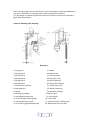
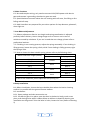
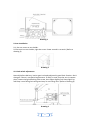
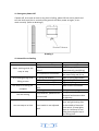
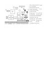
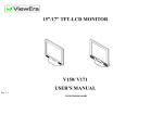
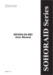
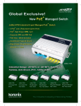
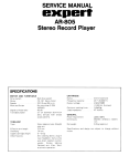
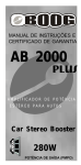
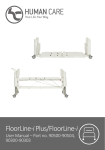
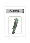
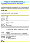
Roanpu Barrier Gates
User Guide
Roanpu Tech Co.,Ltd
Tel:+86 755-81755585 Fax:+86 755 83243332
E-mail:[email protected]
Table of Contents
Brief Description----------------------------------------------------------------------------3
Features--------------------------------------------------------------------------------------3
Technical Parameters----------------------------------------------------------------------3
Notice----------------------------------------------------------------------------------------4
Barrier Working Core Drawing-----------------------------------------------------------4
Main Functions-----------------------------------------------------------------------------5
Arm Balance Adjustment------------------------------------------------------------------5
Body Installation----------------------------------------------------------------------------6
Arm Installation-----------------------------------------------------------------------------7
Limit Switch Adjustment------------------------------------------------------------------7
Emergency Power off----------------------------------------------------------------------8
Normal Errors Dealing---------------------------------------------------------------------8
Remote Control Code---------------------------------------------------------------------9
Packing List----------------------------------------------------------------------------------9
Wiring Diagram---------------------------------------------------------------------------10
2
1. Brief Description
SHINING barrier gates are produced with advanced mechanical-electrical technology
which makes barrier gates to be used more safely, conveniently, and smoothly with
barrier gate automation.
2. Features
2.1. Special running structure: no gear, no belt, which needs no special maintenance
and makes barrier gates work longer.
2.2. Special balance structure makes the arm moving with soft start, fast lifting or fast
falling and soft stop.
2.3. No shaking in all barrier gate arms moving process.
2.4. Arm moving is limited within 90 degrees which avoid accidents happen because
of 360 degree arm moving.
2.5. Special design in integration of slow-speed aluminum-housing motor and
transmission gear box makes barrier gates running without any noise and in good
heat dissipation.
2.6. Smart thermal protection system: control motor temperature in frequent using,
thus motor will never be burnt.
3. Technical Parameters
Power Supply
Frequency
Power Consumption
Working Temperature
Related Humidity
Remote Control Distance
Net Weight
Packed Weight
Packed Dimension
AC110±10% / AC220±10%
50HZ / 60HZ
70Watts
-40°to 85°
≤90%
≤30m
50kgs
55kgs
1090*395*430mm
4. Notice
4.1. Please do not open barrier housing cover hat and door in case of any accident
during barrier gate normal running.
4.2. Wiring has been done inside barrier gate before delivery. Barrier gate can work
by just connecting it with 110V/220V power. No changing before permission.
4.3. Power should have >15A residual current circuit-breaker.
4.4. Please do not put anything on barrier arm and do not let people standing under
barrier arm when arm is falling.
4.5. When power off, to open clutch after closing the power.
4.6. Barrier arm length and spring coordination is adjusted perfectly before delivery.
3
Never change longer arm or shorter arm in case of accidents caused by unbalance. If
you are in need that arm change, please refer to professional workers.
4.7. No change in mechanical and electrical limit switches since they are already in
good working condition.
5. Barrier Working Core Drawing:
Drawing 1
1. Spring Arm
2. Spring Hole 5
3. Spring Hole 4
4. Spring Hole 3
15. Motor
16. Motor Lines
17. Limit Switches
18. Grey (Arm Lift)
5. Spring Hole 2
6. Spring Hole 1
7. Photo-electrical Limit
19. Blue (Common)
20. Green (Arm Falling)
21. Yellow (Arm Lift)
22. White (Common)
23. Red (Arm Falling)
24. Barrier Arm
8. Adjusting Nut
9. Spring
10. Spring Fixing Base
11. Spring Adjustment Nut
12. Arm Lift Light-blocking flake
25. Arm Holder
26. Limit Flake
27. Mechanical Arm Falling Limit
13. Manual Release Clutch
14. Arm Falling Light-blocking flake
28. Mechanical Arm Lift Limit
4
6. Main Functions
6.1. No need complex wiring, only need to connect 110V/220V power with barrier
gate and connect it grounding, then barrier gate can work.
6.2. Special balance structure makes the arm moving with soft start, fast lifting or fast
falling and soft stop.
6.3. Multi-interfaces are prepared for your other options for loop detector, photocell,
alarm light etc.
7. Arm Balance Adjustment
7.1. Balance adjustment: Barrier arm length and spring coordination is adjusted
perfectly before delivery. Never change longer arm or shorter arm in case of
accidents caused by unbalance. If you are in need that arm change, please refer to
professional workers.
7.2. If shaking in arm moving process, adjust the spring reasonably. If arm shaking in
lifting process, loosen the spring a little; while if arm shaking in falling process, tight
the spring a little.
7.3. How to choose the best suitable spring, please refer to the following chart:
Spring
Barrier Gate Arm Length (meter)
Diameter
Spring Hole
6.1-6.5
Hole 1
6.5mm
5.6-6
Hole 2
5.1-5.5
Hole 1
6mm
4.6-5
Hole 2
4.1-4.5
Hole 1
5mm
3-4
Hole 2
2.5-3
Hole 1
4mm
Less than 2.5
Hole 2
If arm is not in balance, please adjust the arm-pulling nut.
8. Body Installation
8.1. Before installation, choose the best suitable place where the barrier housing
surface is in parallel with the ground. Ensure mattess.
8.2. Installation:
8.2.1. Open package and take accessories out.
8.2.2. Put barrier gate in its place, open the door in the barrier body, mark screw
place, and slotting holes which is about 90mm to 100mm in depth for barrier gate
installation on the ground. Twist the bolts in holes, loosen the nuts. (Refer to Drawing
2)
5
Drawing 2
9. Arm Installation
9.1. Put arm cover on arm holder.
9.2 Put arm into arm holder, tight the screw. Power on and it can work. (Refer to
drawing 3)
Drawing 3
10. Limit switch adjustment
Normally before delivery, barrier gate is already adjusted in good limit function. Don’t
change it if there is no special requirement. If really in need, stop the arm in request
place, loosen the light-blocking flake screw, then adjust slightly until lamp lights up,
red lamp is arm falling limit and green lamp is arm lifting limit. (Refer to drawing 4)
Drawing 4
6
11. Emergency Power-Off
If power off, arm stops at level or any place in falling, please lift the arm by hand. And
turn the lutch until arm is vertical to the ground. And later power on again, it can
work normally. (Refer to drawing 5)
Drawing 5
12. Normal Errors Dealing
Normal Error
Motor working while arm
stays at stop
Error Analysis
1. Is power normal?
2. Are connections well
done?
3. Is capacitance connected?
Arm shaking during lift or
falling process
Arm stops as its falling not
complete
Not anti-hitting
Arm not stop at its limit
1. Spring not balance
2. Arm screw is not tight
3. Barrier body not fixed
1. Limit switch is not adjusted
well
2. Spring has no resilience
Loop detector, photocell not
connect well
Limit switch is not adjusted
well
7
Dealing
Pluge power switch
Limit line: grey(Lift)
blue(common) green(falling)
Connect capacitance lines
with motor falling and lift line
Refer to spring adjustment
Tight the arm screw
Tight body fixing screw
Refer to limit connection
Change a new spring
Change new loop detector or
photocell and connect them
in right way
Let arm is level or vertical
place, put light-blocking flake
in the middle of electrical
limit switch, if lamp lights,
then ok.. Red lamp is arm
falling limit and green lamp is
arm lifting limit.
13. Remote control Code
If remote control cannot match barrier gate, please re-code in following way:
A. The code is at the back of each remote control and receiver.
B. Open cover of remote control, take out battery. Check the code pad on the PCB
from right to left. N/C stands for X, up-middle means 1, down-middle means 0. Eg:
code for the following drawing is 10XX0X1X
14. Packing List
Housing (Motor and control panel installed inside)
Arm
Arm Covering Board
Control panel and Motor (Inside housing)
Remote Controller
Arm Support (optional)
Body Door Key
Manual
8
1 unit
1 unit
1 unit
1 set
2 units
1 unit
2 units
1 unit