1
Digital DEC/EDI
OpenVMS User Support Manual-Vol1
Revised for Software Version: Digital DEC/EDI Version 4.0
Compaq Computer Corporation
Houston, Texas
November 2001
©Compaq Computer Corporation 1990,2001
Compaq, the Compaq logo, and VMS Registered in U.S. Patent and trademark Office.
OpenVMS and Tru64 are trademarks of Compaq Information Technologies Group, L.P. in the United States and
other countries.
UNIX is a trademark of The Open Group in the United States and other countries.
All other product names mentioned herein may be trademarks of their respective companies.
Confidential computer software. Valid license from Compaq required for possession, use or copying. Consistent
with FAR 12.211 and 12.212, Commercial Computer Software, Computer Software Documentation, and Technical
Data for Commercial Items are licensed to the U.S. government under vendor's standard commercial license.
Compaq shall not be liable for technical or editorial errors or omissions contained herein. The information in this
document is provided "as is" without warranty of any kind and is subject to change without notice. The warranties
for Compaq products are set forth in the express limited warranty statements accompanying such products. Nothing
herein should be construed as constituting an additional warranty.
This document is the property of, and is proprietary to Compaq Computer Corporation. It is not to be disclosed in
whole or in part without the express written authorization of Compaq Computer Corporation. No portion of this
[enter document] shall be duplicated in any manner for any purpose other than as specifically permitted herein.
Compaq service tool software, including associated documentation, is the property of and contains confidential
technology of Compaq Computer Corporation. Service customer is hereby licensed to use the software only for
activities directly relating to the delivery of, and only during the term of, the applicable services delivered by Compaq or its authorized service provider. Customer may not modify or reverse engineer, remove, or transfer the software or make the software or any resultant diagnosis or system management data available to other parties without
Compaq's or its authorized service provider's consent. Upon termination of the services, customer will, at Compaq's
or its service provider's option, destroy or return the software and associated documentation in its possession.
Printed in the U.S.A.
The following are trademarks of Compaq Computer Corporation:
DEC, DEC/EDI, DIGITAL, OpenVMS, and the Compaq logo.
Adobe is a registered trademark of Adobe Systems Incorporated.
BT is a registered trademark of British Telecommunications plc.
InstallShield is a registered trademark of InstallShield Corporation.
MS and Windows are registered trademarks, and Windows 95, Windows 98, Windows NT and Windows 2000 are
trademarks, of Microsoft Corporation.
Oracle is a registered trademark of Oracle Corporation.
SAP is a registered trademark of SAP AG.
UNIX is a registered trademark in the United States and other countries licensed exclusively through X/Open Company Ltd.
All other trademarks not listed above are acknowledged as the the property of their respective holders.
Contents
Preface
Purpose of This Book . . . . . . . . . . . . . . . . . . . . . . . . . . . . . . . . . . . . . . . . . . 1-xvii
Readership . . . . . . . . . . . . . . . . . . . . . . . . . . . . . . . . . . . . . . . . . . . . . . . . . . . 1-xvii
Related Books . . . . . . . . . . . . . . . . . . . . . . . . . . . . . . . . . . . . . . . . . . . . . . . 1-xviii
Digital DEC/EDI InfoCenter . . . . . . . . . . . . . . . . . . . . . . . . . . . . . . . . . . . . . 1-xix
Related Third Party Documentation . . . . . . . . . . . . . . . . . . . . . . . . . . . . . . . 1-xix
Documentation on Tools Supplied with Digital DEC/EDI . . . . . . . . . . . . . . 1-xix
Typographical conventions . . . . . . . . . . . . . . . . . . . . . . . . . . . . . . . . . . . . . . 1-xxii
Part I
Configuring
Chapter 1
Preparing to Configure Digital DEC/EDI
Starting and Stopping Digital DEC/EDI . . . . . . . . . . . . . . . . . . . . . . . . . . . . . .
Giving Users Access to Digital DEC/EDI . . . . . . . . . . . . . . . . . . . . . . . . . . . .
Administrator Access Rights . . . . . . . . . . . . . . . . . . . . . . . . . . . . . . . . . . .
Supervisor Access Rights . . . . . . . . . . . . . . . . . . . . . . . . . . . . . . . . . . . . . .
Assigning Access Rights . . . . . . . . . . . . . . . . . . . . . . . . . . . . . . . . . . . . . .
Chapter 2
Registering the Digital DEC/EDI Services
What You Must Do . . . . . . . . . . . . . . . . . . . . . . . . . . . . . . . . . . . . . . . . . . . . . .
Registering the Digital DEC/EDI Services . . . . . . . . . . . . . . . . . . . . . . . . . . . .
Specifying Connection-ids . . . . . . . . . . . . . . . . . . . . . . . . . . . . . . . . . . . . .
Connection-ids for VAN Connections . . . . . . . . . . . . . . . . . . . . . . . . . . . .
Registering the Applications . . . . . . . . . . . . . . . . . . . . . . . . . . . . . . . . . . . . . . .
Registering the Client Nodes . . . . . . . . . . . . . . . . . . . . . . . . . . . . . . . . . . . . . .
Defining Logicals in DECEDI$SYLOGICALS.COM . . . . . . . . . . . . . . . . . . .
Chapter 3
1-2
1-3
1-3
1-4
1-4
2-2
2-2
2-4
2-5
2-6
2-7
2-9
Configuring for Application to Application Routing
Setting Up an Application to Application System . . . . . . . . . . . . . . . . . . . . . . 3-1
Configuring the DEC/EDI V4 clients . . . . . . . . . . . . . . . . . . . . . . . . . . . . . 3-1
i
Example of a Site-to-Site System . . . . . . . . . . . . . . . . . . . . . . . . . . . . . . . . 3-2
Chapter 4
Setting up the Translation Services Tables
What You Must Do . . . . . . . . . . . . . . . . . . . . . . . . . . . . . . . . . . . . . . . . . . . . . . 4-1
Identifying the Document to Exchange . . . . . . . . . . . . . . . . . . . . . . . . . . . . . . . 4-3
Caching Profile and Document Definitions . . . . . . . . . . . . . . . . . . . . . . . . . . . 4-4
Creating a Trading Partner Profile . . . . . . . . . . . . . . . . . . . . . . . . . . . . . . . . . . 4-6
Defining the Envelope for an X12 or TDCC Document . . . . . . . . . . . . . . . . . 4-28
Envelopes For TDCC Documents Using GS/GE Segments . . . . . . . . . . 4-29
Identifying the Functional Acknowledgement to Send . . . . . . . . . . . . . . . . . . 4-30
Functional Acknowledgement Document, 997 . . . . . . . . . . . . . . . . . . . . 4-31
Acceptance/Rejection Advice Document, 999 . . . . . . . . . . . . . . . . . . . . . 4-32
EDIFACT CONTRL Message . . . . . . . . . . . . . . . . . . . . . . . . . . . . . . . . . 4-33
Setting Up EDIFACT CONTRL . . . . . . . . . . . . . . . . . . . . . . . . . . . . 4-33
The TRADACOMS Converter & Translator . . . . . . . . . . . . . . . . . . . . . . 4-34
Creating Data Labels . . . . . . . . . . . . . . . . . . . . . . . . . . . . . . . . . . . . . . . . . . . . 4-34
Advanced Features of Data Labels . . . . . . . . . . . . . . . . . . . . . . . . . . . . . . . . . 4-35
Segment Qualifiers . . . . . . . . . . . . . . . . . . . . . . . . . . . . . . . . . . . . . . . . . . 4-38
Qualified Pairs . . . . . . . . . . . . . . . . . . . . . . . . . . . . . . . . . . . . . . . . . . . . . 4-39
Repeating Elements . . . . . . . . . . . . . . . . . . . . . . . . . . . . . . . . . . . . . . . . . 4-41
Specifying Validation for Data Labels . . . . . . . . . . . . . . . . . . . . . . . . . . . . . . 4-41
Scheduling the Transmission File Builder . . . . . . . . . . . . . . . . . . . . . . . . . . . 4-43
Changing a Document for All Trading Partners . . . . . . . . . . . . . . . . . . . . . . . 4-44
Changing the Requirement for a Segment . . . . . . . . . . . . . . . . . . . . . . . . 4-45
Changing a Subelement Definition . . . . . . . . . . . . . . . . . . . . . . . . . . . . . . 4-47
Changing a Document for a Specific Trading Partner . . . . . . . . . . . . . . . . . . 4-48
Deleting a Segment for a Specific Trading Partner . . . . . . . . . . . . . . . . . 4-49
Changing the Trading Partner Code Translation Table . . . . . . . . . . . . . . 4-50
Defining Data Labels for a Specific Trading Partner . . . . . . . . . . . . . . . . 4-51
Defining Inbound User Reference . . . . . . . . . . . . . . . . . . . . . . . . . . . 4-52
X12 Composite Elements . . . . . . . . . . . . . . . . . . . . . . . . . . . . . . . . . . 4-53
Mapping Screen Fields to External Document Fields . . . . . . . . . . . . . . . . . . . 4-54
EDIFACT . . . . . . . . . . . . . . . . . . . . . . . . . . . . . . . . . . . . . . . . . . . . . . . . . 4-54
ii
Chapter 5
Configuring the Translation Service
What the Translation Service Does . . . . . . . . . . . . . . . . . . . . . . . . . . . . . . . . . . 5-1
Summary of What You Must Do . . . . . . . . . . . . . . . . . . . . . . . . . . . . . . . . . . . . 5-2
Defining Trading Partner Profiles . . . . . . . . . . . . . . . . . . . . . . . . . . . . . . . . . . . 5-2
Defining Document Dictionaries . . . . . . . . . . . . . . . . . . . . . . . . . . . . . . . . . . . 5-3
Digital-supplied Definitions . . . . . . . . . . . . . . . . . . . . . . . . . . . . . . . . . . . . 5-3
Modified Definitions . . . . . . . . . . . . . . . . . . . . . . . . . . . . . . . . . . . . . . . . . 5-3
Trading Partner-specific Definitions . . . . . . . . . . . . . . . . . . . . . . . . . . . . . 5-4
Trading Group Specific Definitions - TRADACOMS only . . . . . . . . . . . . 5-5
Local Definitions . . . . . . . . . . . . . . . . . . . . . . . . . . . . . . . . . . . . . . . . . . . . 5-7
Multiple Translation Services . . . . . . . . . . . . . . . . . . . . . . . . . . . . . . . . . . . . . . 5-7
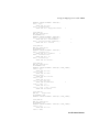
Bypassing the Mapping and Translation Services . . . . . . . . . . . . . . . . . . . . . . 5-7
Configuring for Outbound Batching (X12 and EDIFACT only) . . . . . . . . . . . 5-9
The Behaviour of Outbound Batching . . . . . . . . . . . . . . . . . . . . . . . . . . . . 5-9
Configuration . . . . . . . . . . . . . . . . . . . . . . . . . . . . . . . . . . . . . . . . . . . . . . 5-10
Maximum Mapped Batches . . . . . . . . . . . . . . . . . . . . . . . . . . . . . . . . 5-10
Abort Batch Timeout . . . . . . . . . . . . . . . . . . . . . . . . . . . . . . . . . . . . . 5-10
Chapter 6
Configuring the Mapping Service
What the Mapping Service Does . . . . . . . . . . . . . . . . . . . . . . . . . . . . . . . . . . . .
Summary of What You Must Do . . . . . . . . . . . . . . . . . . . . . . . . . . . . . . . . . . . .
Summary of the Mapping Table Editor . . . . . . . . . . . . . . . . . . . . . . . . . . .
Tracking Mapper Activity . . . . . . . . . . . . . . . . . . . . . . . . . . . . . . . . . . . . .
Further Features of the Mapping Service . . . . . . . . . . . . . . . . . . . . . . . . . . . . .
Chapter 7
6-1
6-2
6-2
6-4
6-4
Configuring the Communication Service
What the Communication Service Does . . . . . . . . . . . . . . . . . . . . . . . . . . . . . .
Summary of What You Must Do . . . . . . . . . . . . . . . . . . . . . . . . . . . . . . . . . . . .
Defining Gateway Parameters . . . . . . . . . . . . . . . . . . . . . . . . . . . . . . . . . . . . . .
Defining a Connection . . . . . . . . . . . . . . . . . . . . . . . . . . . . . . . . . . . . . . . . . . .
Setting Up a Window Schedule . . . . . . . . . . . . . . . . . . . . . . . . . . . . . . . . . . . .
Shutting Down and Restarting a Gateway . . . . . . . . . . . . . . . . . . . . . . . . . . . .
Enabling and Disabling a Gateway . . . . . . . . . . . . . . . . . . . . . . . . . . . . . . . . . .
7-1
7-2
7-3
7-3
7-4
7-5
7-5
iii
Enabling and Disabling a Connection . . . . . . . . . . . . . . . . . . . . . . . . . . . . . . . . 7-5
Setting Up Special Gateway Functionality . . . . . . . . . . . . . . . . . . . . . . . . . . . . 7-6
Auto Submit for Non-Job-Oriented Gateways . . . . . . . . . . . . . . . . . . . . . . 7-6
Chapter 8
Setting Up the 3780Plus Gateway
What You Must Do . . . . . . . . . . . . . . . . . . . . . . . . . . . . . . . . . . . . . . . . . . . . . . 8-1
Setting the Port Attributes . . . . . . . . . . . . . . . . . . . . . . . . . . . . . . . . . . 8-2
Add 3780Plus Startup/Shutdown to OpenVMS Startup/Shutdown . . . 8-3
Prerequisite Tasks . . . . . . . . . . . . . . . . . . . . . . . . . . . . . . . . . . . . . . . . . . . . 8-4
CLEO 3780 Blocking Factor Field . . . . . . . . . . . . . . . . . . . . . . . . . . . . . . . 8-7
Editing the 3780Plus Control Files . . . . . . . . . . . . . . . . . . . . . . . . . . . . . . . . . . 8-7
Defining Gateway Parameters . . . . . . . . . . . . . . . . . . . . . . . . . . . . . . . . . . . . . 8-11
Defining the Connection . . . . . . . . . . . . . . . . . . . . . . . . . . . . . . . . . . . . . . . . . 8-14
Defining Window Schedules . . . . . . . . . . . . . . . . . . . . . . . . . . . . . . . . . . . . . . 8-27
Defining and Scheduling Jobs . . . . . . . . . . . . . . . . . . . . . . . . . . . . . . . . . . . . . 8-29
DEFINING NODE DETAILS . . . . . . . . . . . . . . . . . . . . . . . . . . . . . . . . . . . . 8-32
Starting the 3780Plus Gateway . . . . . . . . . . . . . . . . . . . . . . . . . . . . . . . . . . . . 8-34
Enabling and Disabling the 3780Plus Gateway . . . . . . . . . . . . . . . . . . . . . . . 8-35
Enabling a 3780Plus Connection . . . . . . . . . . . . . . . . . . . . . . . . . . . . . . . . . . 8-36
Starting a Connection Manually . . . . . . . . . . . . . . . . . . . . . . . . . . . . . . . . . . . 8-37
Setting Up For Specific VANs . . . . . . . . . . . . . . . . . . . . . . . . . . . . . . . . . . . . 8-37
Setting Up for EDI*EXPRESS . . . . . . . . . . . . . . . . . . . . . . . . . . . . . . . . . 8-37
Setting Up for EDI*NET . . . . . . . . . . . . . . . . . . . . . . . . . . . . . . . . . . . . . 8-40
Log Files and Errors . . . . . . . . . . . . . . . . . . . . . . . . . . . . . . . . . . . . . . . . . . . . 8-43
Example of the Job Log File . . . . . . . . . . . . . . . . . . . . . . . . . . . . . . . . . . . 8-44
Example of the 3780Plus Log File . . . . . . . . . . . . . . . . . . . . . . . . . . . . . . 8-47
Example of the Monitor Log File (Extract) . . . . . . . . . . . . . . . . . . . . . . . 8-48
Chapter 9
Setting Up the X.25 (TRADANET) Gateway
What You Must Do . . . . . . . . . . . . . . . . . . . . . . . . . . . . . . . . . . . . . . . . . . . . . .
Prerequisite Tasks . . . . . . . . . . . . . . . . . . . . . . . . . . . . . . . . . . . . . . . . . . . .
Summary Checklist for TRADANET . . . . . . . . . . . . . . . . . . . . . . . . . . . .
Defining Gateway Parameters . . . . . . . . . . . . . . . . . . . . . . . . . . . . . . . . . . . . . .
9-1
9-2
9-3
9-5
iv
Defining the Connection . . . . . . . . . . . . . . . . . . . . . . . . . . . . . . . . . . . . . . . . . . 9-8
Defining Window Schedules . . . . . . . . . . . . . . . . . . . . . . . . . . . . . . . . . . . . . . 9-17
Defining and Scheduling Jobs . . . . . . . . . . . . . . . . . . . . . . . . . . . . . . . . . . . . . 9-19
Defining NODE Details . . . . . . . . . . . . . . . . . . . . . . . . . . . . . . . . . . . . . . . . . 9-23
Defining VAN-specific Options . . . . . . . . . . . . . . . . . . . . . . . . . . . . . . . . . . . 9-24
Multiple TRADANET Mailbox Support . . . . . . . . . . . . . . . . . . . . . . . . . 9-24
Session Contents Control . . . . . . . . . . . . . . . . . . . . . . . . . . . . . . . . . . . . . 9-25
Auto-recovery and Reduced Transmission Costs . . . . . . . . . . . . . . . . . . . 9-25
TRADANET Integration . . . . . . . . . . . . . . . . . . . . . . . . . . . . . . . . . . . . . 9-26
Detection of undelivered transmission files . . . . . . . . . . . . . . . . . . . . . . . 9-26
Synchronizing TRADANET Passwords . . . . . . . . . . . . . . . . . . . . . . . . . 9-27
Establishing and Viewing Relationships . . . . . . . . . . . . . . . . . . . . . . . . . 9-28
Viewing Mailbox and Postbox Reports . . . . . . . . . . . . . . . . . . . . . . . . . . 9-30
Identifying Documents . . . . . . . . . . . . . . . . . . . . . . . . . . . . . . . . . . . . . . . 9-30
Transmission File Re-sends, Read Receipts, and the New Audit Log Trail . .
9-31
Refetching Documents from TRADANET . . . . . . . . . . . . . . . . . . . . . . . 9-32
Logicals affecting the X.25 Gateway . . . . . . . . . . . . . . . . . . . . . . . . . . . . . . . 9-33
Starting the X.25 Gateway . . . . . . . . . . . . . . . . . . . . . . . . . . . . . . . . . . . . . . . 9-34
Enabling and Disabling the X.25 Gateway . . . . . . . . . . . . . . . . . . . . . . . . . . . 9-35
Enabling an X.25 Connection . . . . . . . . . . . . . . . . . . . . . . . . . . . . . . . . . . . . . 9-36
Starting a Connection Manually . . . . . . . . . . . . . . . . . . . . . . . . . . . . . . . . . . . 9-37
Chapter 10
Setting Up the Import/Export Gateway
What You Must Do . . . . . . . . . . . . . . . . . . . . . . . . . . . . . . . . . . . . . . . . . . . . . 10-1
Defining Gateway Parameters . . . . . . . . . . . . . . . . . . . . . . . . . . . . . . . . . . . . . 10-2
Defining the Connection . . . . . . . . . . . . . . . . . . . . . . . . . . . . . . . . . . . . . . . . . 10-5
Defining Window Schedules . . . . . . . . . . . . . . . . . . . . . . . . . . . . . . . . . . . . . 10-10
Defining and Scheduling Jobs . . . . . . . . . . . . . . . . . . . . . . . . . . . . . . . . . . . . 10-12
Defining NODE Details . . . . . . . . . . . . . . . . . . . . . . . . . . . . . . . . . . . . . . . . 10-14
Creating the Directories Used by the Import/Export Gateway . . . . . . . . . . . 10-14
Setting Directory Protections . . . . . . . . . . . . . . . . . . . . . . . . . . . . . . . . . 10-14
Limiting the Versions of Import Files . . . . . . . . . . . . . . . . . . . . . . . . . . . 10-15
File Naming Convention . . . . . . . . . . . . . . . . . . . . . . . . . . . . . . . . . . . . 10-15
v
Starting the Import/Export Gateway . . . . . . . . . . . . . . . . . . . . . . . . . . . . . . .
Enabling and Disabling the Import/Export Gateway . . . . . . . . . . . . . . . . . .
Enabling an Import/Export Connection . . . . . . . . . . . . . . . . . . . . . . . . . . . .
Starting a Connection Manually . . . . . . . . . . . . . . . . . . . . . . . . . . . . . . . . . .
Chapter 11
10-15
10-16
10-17
10-18
Setting Up the OFTP Gateway
What You Must Do . . . . . . . . . . . . . . . . . . . . . . . . . . . . . . . . . . . . . . . . . . . . . 11-1
Prerequisite Tasks . . . . . . . . . . . . . . . . . . . . . . . . . . . . . . . . . . . . . . . . . . . 11-2
Defining Gateway Parameters . . . . . . . . . . . . . . . . . . . . . . . . . . . . . . . . . . . . . 11-3
Defining the Connection . . . . . . . . . . . . . . . . . . . . . . . . . . . . . . . . . . . . . . . . . 11-8
Defining Trading Partner-Specific Parameters . . . . . . . . . . . . . . . . . . . . . . . 11-13
Defining Connection Specific Logical Names . . . . . . . . . . . . . . . . . . . . . . . 11-15
Call User Data . . . . . . . . . . . . . . . . . . . . . . . . . . . . . . . . . . . . . . . . . . . . 11-15
Special Logic Modulo . . . . . . . . . . . . . . . . . . . . . . . . . . . . . . . . . . . . . . 11-16
EERP Sending Priority . . . . . . . . . . . . . . . . . . . . . . . . . . . . . . . . . . . . . . 11-16
Defining Window Schedules . . . . . . . . . . . . . . . . . . . . . . . . . . . . . . . . . . . . . 11-17
Defining NODE Details . . . . . . . . . . . . . . . . . . . . . . . . . . . . . . . . . . . . . . . . 11-18
Starting the OFTP Gateway . . . . . . . . . . . . . . . . . . . . . . . . . . . . . . . . . . . . . 11-19
Enabling and Disabling the OFTP Gateway . . . . . . . . . . . . . . . . . . . . . . . . . 11-19
Enabling an OFTP Connection . . . . . . . . . . . . . . . . . . . . . . . . . . . . . . . . . . . 11-20
Starting a Connection Manually . . . . . . . . . . . . . . . . . . . . . . . . . . . . . . . . . . 11-21
Chapter 12
Setting Up the Pedi Gateway
Prerequisites . . . . . . . . . . . . . . . . . . . . . . . . . . . . . . . . . . . . . . . . . . . . . . . . . . 12-2
Setting Up The Mailbus MTA to Support The Digital DEC/EDI User Agent 12-2
Defining the Pedi Gateway as a User Agent . . . . . . . . . . . . . . . . . . . . . . 12-2
Defining the O/R Address Served by the Digital DEC/EDI User Agent . 12-3
Defining O/R Addresses for Trading Partners and VANs . . . . . . . . . . . . 12-5
Supported Elements of Service . . . . . . . . . . . . . . . . . . . . . . . . . . . . . . . . . 12-7
What You Must Do In Digital DEC/EDI . . . . . . . . . . . . . . . . . . . . . . . . . . . 12-13
Defining Gateway Parameters . . . . . . . . . . . . . . . . . . . . . . . . . . . . . . . . 12-14
Defining the Connection . . . . . . . . . . . . . . . . . . . . . . . . . . . . . . . . . . . . . 12-17
Defining Window Schedules . . . . . . . . . . . . . . . . . . . . . . . . . . . . . . . . . 12-27
vi
Defining NODE Details . . . . . . . . . . . . . . . . . . . . . . . . . . . . . . . . . . . . . . . .
Starting the Digital DEC/EDI Pedi Gateway . . . . . . . . . . . . . . . . . . . . .
Enabling the Digital DEC/EDI Pedi Gateway . . . . . . . . . . . . . . . . . . . .
Enabling a Pedi Connection . . . . . . . . . . . . . . . . . . . . . . . . . . . . . . . . . .
Starting a Connection Manually . . . . . . . . . . . . . . . . . . . . . . . . . . . . . . .
EDI Notification . . . . . . . . . . . . . . . . . . . . . . . . . . . . . . . . . . . . . . . . . . . . . .
Tips for Testing . . . . . . . . . . . . . . . . . . . . . . . . . . . . . . . . . . . . . . . . . . . . . . .
Turn on the MTA Message History Logging . . . . . . . . . . . . . . . . . . . . .
Use the Pedi User Agent Debug Logical Names . . . . . . . . . . . . . . . . . .
Decode the ASN.1 Message Content . . . . . . . . . . . . . . . . . . . . . . . . . . .
Chapter 13
12-30
12-30
12-30
12-31
12-32
12-32
12-33
12-33
12-33
12-34
Exchanging Files Outside Normal Schedule
What You Must Do . . . . . . . . . . . . . . . . . . . . . . . . . . . . . . . . . . . . . . . . . . . . .
Scheduling a One-time Window . . . . . . . . . . . . . . . . . . . . . . . . . . . . . . . . . . .
Starting a Connection Manually on Demand . . . . . . . . . . . . . . . . . . . . . . . . .
Scheduling a Job Exception . . . . . . . . . . . . . . . . . . . . . . . . . . . . . . . . . . . . . .
Example of Using One-time Windows and Job Exceptions . . . . . . . . . . . . . .
Chapter 14
13-1
13-2
13-3
13-3
13-5
Testing the Configuration (CVP)
What the CVP Does . . . . . . . . . . . . . . . . . . . . . . . . . . . . . . . . . . . . . . . . . . . . 14-1
How the CVP Routes Documents . . . . . . . . . . . . . . . . . . . . . . . . . . . . . . . . . . 14-2
Prerequisites for Running the CVP . . . . . . . . . . . . . . . . . . . . . . . . . . . . . . . . . 14-2
How to Run the CVP . . . . . . . . . . . . . . . . . . . . . . . . . . . . . . . . . . . . . . . . . . . . 14-4
Setting Up Definitions for the CVP . . . . . . . . . . . . . . . . . . . . . . . . . . . . . 14-5
Shutting Down and Restarting Digital DEC/EDI . . . . . . . . . . . . . . . . . . . 14-7
Starting the CVP . . . . . . . . . . . . . . . . . . . . . . . . . . . . . . . . . . . . . . . . . . . . 14-7
Responding to Questions from the CVP . . . . . . . . . . . . . . . . . . . . . . . . . . 14-7
Exporting and Importing the Transmission File . . . . . . . . . . . . . . . . . . . . 14-9
The CVP Report . . . . . . . . . . . . . . . . . . . . . . . . . . . . . . . . . . . . . . . . . . . . 14-9
Tidying Up After Running the CVP . . . . . . . . . . . . . . . . . . . . . . . . . . . . 14-10
Examples of Running the CVP . . . . . . . . . . . . . . . . . . . . . . . . . . . . . . . . . . . 14-10
CVP Log . . . . . . . . . . . . . . . . . . . . . . . . . . . . . . . . . . . . . . . . . . . . . . . . . 14-10
CVP Report . . . . . . . . . . . . . . . . . . . . . . . . . . . . . . . . . . . . . . . . . . . . . . . 14-11
vii
Chapter 15
Testing the Translation Service
What You Must Do . . . . . . . . . . . . . . . . . . . . . . . . . . . . . . . . . . . . . . . . . . . . .
Developing the Applications . . . . . . . . . . . . . . . . . . . . . . . . . . . . . . . . . . . . . .
Registering the Gateway and Connection-id . . . . . . . . . . . . . . . . . . . . . . . . . .
Registering the Applications . . . . . . . . . . . . . . . . . . . . . . . . . . . . . . . . . . . . . .
Creating a Trading Partner Profile and Agreements . . . . . . . . . . . . . . . . . . . .
Defining the Connection Characteristics . . . . . . . . . . . . . . . . . . . . . . . . . . . .
Setting Up the Default Import/Export Directories . . . . . . . . . . . . . . . . . . . . .
Running the Test . . . . . . . . . . . . . . . . . . . . . . . . . . . . . . . . . . . . . . . . . . . . . . .
Comparing the Sent and Received Documents . . . . . . . . . . . . . . . . . . . . . . . .
Modifying Digital DEC/EDI to Exchange Live Documents . . . . . . . . . . . . .
Part II
15-1
15-2
15-2
15-3
15-3
15-4
15-5
15-6
15-7
15-8
Maintaining
Chapter 16
Summary of Management Tasks
Start and Stop Digital DEC/EDI . . . . . . . . . . . . . . . . . . . . . . . . . . . . . . . . . . .
Start a New Error Log . . . . . . . . . . . . . . . . . . . . . . . . . . . . . . . . . . . . . . .
Check for Failed Documents and Transmission Files . . . . . . . . . . . . . . . . . . .
Manage the Communication Service . . . . . . . . . . . . . . . . . . . . . . . . . . . . . . .
Archive Data . . . . . . . . . . . . . . . . . . . . . . . . . . . . . . . . . . . . . . . . . . . . . . . . . .
Optimize the Audit Database . . . . . . . . . . . . . . . . . . . . . . . . . . . . . . . . . . . . .
Solve Problems . . . . . . . . . . . . . . . . . . . . . . . . . . . . . . . . . . . . . . . . . . . . . . . .
Monitor and Maintain Performance . . . . . . . . . . . . . . . . . . . . . . . . . . . . . . . .
Modify Digital DEC/EDI Logical Names . . . . . . . . . . . . . . . . . . . . . . . .
Reschedule . . . . . . . . . . . . . . . . . . . . . . . . . . . . . . . . . . . . . . . . . . . . . . . .
Start or Stop Digital DEC/EDI Components . . . . . . . . . . . . . . . . . . . . . .
Add Storage Directories . . . . . . . . . . . . . . . . . . . . . . . . . . . . . . . . . . . . . .
Add or Remove Users . . . . . . . . . . . . . . . . . . . . . . . . . . . . . . . . . . . . . . . .
Management Commands . . . . . . . . . . . . . . . . . . . . . . . . . . . . . . . . . . . . . . . . .
Chapter 17
16-1
16-1
16-2
16-2
16-2
16-3
16-3
16-3
16-3
16-3
16-4
16-4
16-4
16-4
Starting and Stopping Digital DEC/EDI
Starting Digital DEC/EDI . . . . . . . . . . . . . . . . . . . . . . . . . . . . . . . . . . . . . . . . 17-1
viii
Stopping Digital DEC/EDI . . . . . . . . . . . . . . . . . . . . . . . . . . . . . . . . . . . . . . .
Starting a New Error Log . . . . . . . . . . . . . . . . . . . . . . . . . . . . . . . . . . . . . . . .
Viewing the Error Log . . . . . . . . . . . . . . . . . . . . . . . . . . . . . . . . . . . . . . . . . .
Getting Notification of Errors by Mail . . . . . . . . . . . . . . . . . . . . . . . . . . . . . .
Adding or Removing Digital DEC/EDI Users . . . . . . . . . . . . . . . . . . . . . . . .
Chapter 18
17-2
17-2
17-3
17-4
17-5
Archiving and Retrieving Data
Automatic Archiving Using the Archive Server . . . . . . . . . . . . . . . . . . . . . . . 18-1
Archiving to Tape or Disk . . . . . . . . . . . . . . . . . . . . . . . . . . . . . . . . . . . . . . . . 18-2
Retrieving Archived Data . . . . . . . . . . . . . . . . . . . . . . . . . . . . . . . . . . . . . . . . 18-4
Chapter 19
Managing the Communication Service
Gateway Management . . . . . . . . . . . . . . . . . . . . . . . . . . . . . . . . . . . . . . . . . . . 19-1
Connection Management . . . . . . . . . . . . . . . . . . . . . . . . . . . . . . . . . . . . . . . . 19-2
Naming Conventions for Transmission Files . . . . . . . . . . . . . . . . . . . . . . . . . 19-4
Naming Conventions for Transmission Files with Faults . . . . . . . . . . . . 19-4
Managing Transmission Files . . . . . . . . . . . . . . . . . . . . . . . . . . . . . . . . . . . . . 19-4
Viewing Details of Transmission Files . . . . . . . . . . . . . . . . . . . . . . . . . . . 19-7
Resetting a Transmission File . . . . . . . . . . . . . . . . . . . . . . . . . . . . . . . . . . 19-8
Resending a Transmission File . . . . . . . . . . . . . . . . . . . . . . . . . . . . . . . . . 19-8
Setting Up and Scheduling Jobs . . . . . . . . . . . . . . . . . . . . . . . . . . . . . . . . . . . 19-9
Setting Up Jobs for the X.25 Gateways . . . . . . . . . . . . . . . . . . . . . . . . . . 19-9
Setting Up Jobs for the Import/Export Gateway . . . . . . . . . . . . . . . . . . 19-10
Scheduling the Times at Which Jobs Run . . . . . . . . . . . . . . . . . . . . . . . 19-10
Scheduling Windows . . . . . . . . . . . . . . . . . . . . . . . . . . . . . . . . . . . . . . . 19-12
Exchanging Transmission Files Outside the Normal Schedule . . . . . . . . . . 19-14
Scheduling One-time Windows . . . . . . . . . . . . . . . . . . . . . . . . . . . . . . . 19-15
Scheduling an Exception Job . . . . . . . . . . . . . . . . . . . . . . . . . . . . . . . . . 19-15
Starting a Job on Demand . . . . . . . . . . . . . . . . . . . . . . . . . . . . . . . . . . . . 19-17
Example of Using One-time Windows and Exception Jobs . . . . . . . . . . 19-18
VAN-Specific Information . . . . . . . . . . . . . . . . . . . . . . . . . . . . . . . . . . . . . . 19-19
Changing the TRADANET Password . . . . . . . . . . . . . . . . . . . . . . . . . . 19-19
Examining TRADANET Reports and Relationships . . . . . . . . . . . . . . . 19-21
TRADANET Excess Mailbox Charge Messages . . . . . . . . . . . . . . . . . . 19-22
ix
Chapter 20
Improving Performance
Modifying Digital DEC/EDI Logical Names . . . . . . . . . . . . . . . . . . . . . . . . . 20-1
Changing the Number of Storage Directories . . . . . . . . . . . . . . . . . . . . . . . . . 20-7
Adding More Storage Directories . . . . . . . . . . . . . . . . . . . . . . . . . . . . . . . 20-8
Controlling the Use of Storage Directories . . . . . . . . . . . . . . . . . . . . . . . 20-9
Optimizing the Rdb Databases . . . . . . . . . . . . . . . . . . . . . . . . . . . . . . . . . . . . 20-9
Resizing the Database . . . . . . . . . . . . . . . . . . . . . . . . . . . . . . . . . . . . . . . 20-10
Distributing the Database across Multiple Disks . . . . . . . . . . . . . . . . . . 20-11
Adding Converters and Translators . . . . . . . . . . . . . . . . . . . . . . . . . . . . . . . . 20-12
Maximum Number of Converters . . . . . . . . . . . . . . . . . . . . . . . . . . . . . . 20-13
Maximum Number of Translators . . . . . . . . . . . . . . . . . . . . . . . . . . . . . 20-14
Reducing Sorting Done by the Convertors . . . . . . . . . . . . . . . . . . . . . . . . . . 20-14
Changing System Parameters . . . . . . . . . . . . . . . . . . . . . . . . . . . . . . . . . . . . 20-15
Part III
Command Reference
Chapter 21
Introduction to Digital DEC/EDI Commands
Using This Part . . . . . . . . . . . . . . . . . . . . . . . . . . . . . . . . . . . . . . . . . . . . . . . . 21-1
Using Digital DEC/EDI Commands . . . . . . . . . . . . . . . . . . . . . . . . . . . . . . . . 21-2
Format of the Commands . . . . . . . . . . . . . . . . . . . . . . . . . . . . . . . . . . . . . . . . 21-3
/Standard and /Version Qualifiers . . . . . . . . . . . . . . . . . . . . . . . . . . . . . . . . . . 21-3
/Brief and /Full Qualifiers . . . . . . . . . . . . . . . . . . . . . . . . . . . . . . . . . . . . . . . . 21-4
/Output and /Queue Qualifiers . . . . . . . . . . . . . . . . . . . . . . . . . . . . . . . . . . . . 21-5
Naming Rules . . . . . . . . . . . . . . . . . . . . . . . . . . . . . . . . . . . . . . . . . . . . . . . . . 21-5
Using the Screens and Keyboard . . . . . . . . . . . . . . . . . . . . . . . . . . . . . . . . . . 21-6
Access Rights and Commands . . . . . . . . . . . . . . . . . . . . . . . . . . . . . . . . . . . 21-15
Chapter 22
Digital DEC/EDI Command Reference - Commands A - F
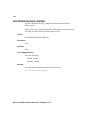
ADD USER . . . . . . . . . . . . . . . . . . . . . . . . . . . . . . . . . . . . . . . . . . . . . . . 22-1
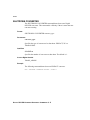
ARCHIVE . . . . . . . . . . . . . . . . . . . . . . . . . . . . . . . . . . . . . . . . . . . . . . . . 22-4
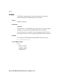
BUILD CACHE . . . . . . . . . . . . . . . . . . . . . . . . . . . . . . . . . . . . . . . . . . . . 22-8
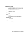
CANCEL BATCH . . . . . . . . . . . . . . . . . . . . . . . . . . . . . . . . . . . . . . . . . 22-11
DISABLE CONNECTION . . . . . . . . . . . . . . . . . . . . . . . . . . . . . . . . . . 22-13
x
DISABLE GATEWAY . . . . . . . . . . . . . . . . . . . . . . . . . . . . . . . . . . . . . . 22-15
EDIT CODES . . . . . . . . . . . . . . . . . . . . . . . . . . . . . . . . . . . . . . . . . . . . . 22-17
EDIT CONFIGURATION . . . . . . . . . . . . . . . . . . . . . . . . . . . . . . . . . . . 22-21
EDIT CONNECTION . . . . . . . . . . . . . . . . . . . . . . . . . . . . . . . . . . . . . . 22-42
EDIT DATA_LABELS . . . . . . . . . . . . . . . . . . . . . . . . . . . . . . . . . . . . . . 22-45
EDIT ELEMENT_DICTIONARY . . . . . . . . . . . . . . . . . . . . . . . . . . . . . 22-53
EDIT ENVELOPE . . . . . . . . . . . . . . . . . . . . . . . . . . . . . . . . . . . . . . . . . 22-57
EDIT FORMAT . . . . . . . . . . . . . . . . . . . . . . . . . . . . . . . . . . . . . . . . . . . 22-61
EDIT MAPPING_TABLE . . . . . . . . . . . . . . . . . . . . . . . . . . . . . . . . . . . 22-66
EDIT PARAMETER . . . . . . . . . . . . . . . . . . . . . . . . . . . . . . . . . . . . . . . 22-67
EDIT PROFILE . . . . . . . . . . . . . . . . . . . . . . . . . . . . . . . . . . . . . . . . . . . 22-69
EDIT SEGMENT_DICTIONARY . . . . . . . . . . . . . . . . . . . . . . . . . . . . 22-107
EDIT SITE . . . . . . . . . . . . . . . . . . . . . . . . . . . . . . . . . . . . . . . . . . . . . . 22-113
EDIT SUB_ELEMENT_DICTIONARY . . . . . . . . . . . . . . . . . . . . . . . 22-116
EDIT TABLES . . . . . . . . . . . . . . . . . . . . . . . . . . . . . . . . . . . . . . . . . . . 22-122
EDIT VALUE_VALIDATION . . . . . . . . . . . . . . . . . . . . . . . . . . . . . . . 22-137
ENABLE CONNECTION . . . . . . . . . . . . . . . . . . . . . . . . . . . . . . . . . . 22-140
ENABLE GATEWAY . . . . . . . . . . . . . . . . . . . . . . . . . . . . . . . . . . . . . 22-141
EXTRACT PROFILE . . . . . . . . . . . . . . . . . . . . . . . . . . . . . . . . . . . . . . 22-143
EXIT . . . . . . . . . . . . . . . . . . . . . . . . . . . . . . . . . . . . . . . . . . . . . . . . . . . 22-145
Chapter 23
Digital DEC/EDI Command Reference -Commands G - L
HELP . . . . . . . . . . . . . . . . . . . . . . . . . . . . . . . . . . . . . . . . . . . . . . . . . . . . 23-1
INTERCHANGE . . . . . . . . . . . . . . . . . . . . . . . . . . . . . . . . . . . . . . . . . . . 23-3
LIST BATCH . . . . . . . . . . . . . . . . . . . . . . . . . . . . . . . . . . . . . . . . . . . . . . 23-4
LIST CODES . . . . . . . . . . . . . . . . . . . . . . . . . . . . . . . . . . . . . . . . . . . . . . 23-8
LIST CONNECTION . . . . . . . . . . . . . . . . . . . . . . . . . . . . . . . . . . . . . . . 23-11
LIST DATA_LABELS . . . . . . . . . . . . . . . . . . . . . . . . . . . . . . . . . . . . . . 23-14
LIST DOCUMENT . . . . . . . . . . . . . . . . . . . . . . . . . . . . . . . . . . . . . . . . 23-18
LIST ELEMENT_DICTIONARY . . . . . . . . . . . . . . . . . . . . . . . . . . . . . 23-36
LIST ENVELOPE . . . . . . . . . . . . . . . . . . . . . . . . . . . . . . . . . . . . . . . . . 23-40
LIST FORMAT . . . . . . . . . . . . . . . . . . . . . . . . . . . . . . . . . . . . . . . . . . . . 23-42
LIST PARAMETER . . . . . . . . . . . . . . . . . . . . . . . . . . . . . . . . . . . . . . . . 23-44
LIST PROFILE . . . . . . . . . . . . . . . . . . . . . . . . . . . . . . . . . . . . . . . . . . . . 23-47
LIST SEGMENT_DICTIONARY . . . . . . . . . . . . . . . . . . . . . . . . . . . . . 23-50
LIST SITE . . . . . . . . . . . . . . . . . . . . . . . . . . . . . . . . . . . . . . . . . . . . . . . 23-55
xi
LIST SUB_ELEMENT_DICTIONARY . . . . . . . . . . . . . . . . . . . . . . .
LIST TABLES . . . . . . . . . . . . . . . . . . . . . . . . . . . . . . . . . . . . . . . . . . .
LIST TRANSMISSION . . . . . . . . . . . . . . . . . . . . . . . . . . . . . . . . . . . .
LIST USER . . . . . . . . . . . . . . . . . . . . . . . . . . . . . . . . . . . . . . . . . . . . . .
LIST VALUE_VALIDATION . . . . . . . . . . . . . . . . . . . . . . . . . . . . . . .
Chapter 24
23-59
23-65
23-78
23-89
23-91
Digital DEC/EDI Command Reference -Commands M - R
LOAD PROFILE . . . . . . . . . . . . . . . . . . . . . . . . . . . . . . . . . . . . . . . . . . 24-1
MODIFY USER . . . . . . . . . . . . . . . . . . . . . . . . . . . . . . . . . . . . . . . . . . . 24-3
REMOVE USER . . . . . . . . . . . . . . . . . . . . . . . . . . . . . . . . . . . . . . . . . . . 24-5
REPLACE CACHE . . . . . . . . . . . . . . . . . . . . . . . . . . . . . . . . . . . . . . . . 24-6
RESET DOCUMENT . . . . . . . . . . . . . . . . . . . . . . . . . . . . . . . . . . . . . . . 24-9
RESET TRANSMISSION . . . . . . . . . . . . . . . . . . . . . . . . . . . . . . . . . . 24-14
RETRIEVE . . . . . . . . . . . . . . . . . . . . . . . . . . . . . . . . . . . . . . . . . . . . . . 24-17
REVIEW DOCUMENT . . . . . . . . . . . . . . . . . . . . . . . . . . . . . . . . . . . . 24-19
REVIEW TRANSMISSION . . . . . . . . . . . . . . . . . . . . . . . . . . . . . . . . . 24-21
Chapter 25
Digital DEC/EDI Command Reference -Commands S - Z
SET BUILD_INTERVAL . . . . . . . . . . . . . . . . . . . . . . . . . . . . . . . . . . . . 25-1
SET STANDARD_DEFAULT . . . . . . . . . . . . . . . . . . . . . . . . . . . . . . . . 25-3
SHOW BUILD_INTERVAL . . . . . . . . . . . . . . . . . . . . . . . . . . . . . . . . . . 25-5
SHOW STANDARD_DEFAULT . . . . . . . . . . . . . . . . . . . . . . . . . . . . . . 25-6
SHOW VERSION . . . . . . . . . . . . . . . . . . . . . . . . . . . . . . . . . . . . . . . . . . 25-7
SHUTDOWN ARCHIVE_SERVER . . . . . . . . . . . . . . . . . . . . . . . . . . . 25-8
SHUTDOWN BUILDER . . . . . . . . . . . . . . . . . . . . . . . . . . . . . . . . . . . . 25-9
SHUTDOWN CONVERTER . . . . . . . . . . . . . . . . . . . . . . . . . . . . . . . . 25-10
SHUTDOWN GATEWAY . . . . . . . . . . . . . . . . . . . . . . . . . . . . . . . . . . . 25-11
SHUTDOWN SCHEDULER . . . . . . . . . . . . . . . . . . . . . . . . . . . . . . . . 25-12
SHUTDOWN TRANSLATOR . . . . . . . . . . . . . . . . . . . . . . . . . . . . . . . 25-13
SPAWN . . . . . . . . . . . . . . . . . . . . . . . . . . . . . . . . . . . . . . . . . . . . . . . . . 25-14
START ARCHIVE_SERVER . . . . . . . . . . . . . . . . . . . . . . . . . . . . . . . . 25-15
START BUILDER . . . . . . . . . . . . . . . . . . . . . . . . . . . . . . . . . . . . . . . . 25-16
START CONNECTION . . . . . . . . . . . . . . . . . . . . . . . . . . . . . . . . . . . . 25-17
START CONVERTER . . . . . . . . . . . . . . . . . . . . . . . . . . . . . . . . . . . . . 25-19
START GATEWAY . . . . . . . . . . . . . . . . . . . . . . . . . . . . . . . . . . . . . . . . 25-20
xii
START SCHEDULER . . . . . . . . . . . . . . . . . . . . . . . . . . . . . . . . . . . . . . 25-21
START TRANSLATOR . . . . . . . . . . . . . . . . . . . . . . . . . . . . . . . . . . . . . 25-22
VERIFY STATUS . . . . . . . . . . . . . . . . . . . . . . . . . . . . . . . . . . . . . . . . . 25-23
Part IV
Using the Mapper
Chapter 26
Overview of Mapping Service
Features of Mapping Service . . . . . . . . . . . . . . . . . . . . . . . . . . . . . . . . . . . . . 26-1
Chapter 27
The Components of Mapping Service
How Mapping Service Works . . . . . . . . . . . . . . . . . . . . . . . . . . . . . . . . . . . . . 27-2
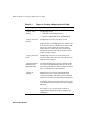
Chapter 28
An Outgoing Invoice
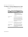
The Stages in Creating a Mapping Service Table . . . . . . . . . . . . . . . . . . . . . . 28-2
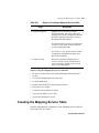
Creating the Mapping Service Table . . . . . . . . . . . . . . . . . . . . . . . . . . . . . . . . 28-3
Specifying Table Attributes . . . . . . . . . . . . . . . . . . . . . . . . . . . . . . . . . . . . . . . 28-4
The Purpose of the Application Id . . . . . . . . . . . . . . . . . . . . . . . . . . . . . . 28-6
Specifying the Record Sequence . . . . . . . . . . . . . . . . . . . . . . . . . . . . . . . . . . . 28-7
Defining Record Attributes . . . . . . . . . . . . . . . . . . . . . . . . . . . . . . . . . . . 28-9
Specifying the Record Layout . . . . . . . . . . . . . . . . . . . . . . . . . . . . . . . . . . . . 28-12
Importing Document Definitions From Digital DEC/EDI . . . . . . . . . . . . . . 28-15
Importing The Document Definition From Local Translation Node . . . 28-16
Importing The Document Definition From Remote Translation Node . 28-18
Specifying the Mappings . . . . . . . . . . . . . . . . . . . . . . . . . . . . . . . . . . . . . . . . 28-19
Index of Mapping Sets . . . . . . . . . . . . . . . . . . . . . . . . . . . . . . . . . . . . . . 28-19
Index of Maps . . . . . . . . . . . . . . . . . . . . . . . . . . . . . . . . . . . . . . . . . . . . . 28-20
Mapping Fields to Segments . . . . . . . . . . . . . . . . . . . . . . . . . . . . . . . . . 28-21
Creating Mappings for Segments . . . . . . . . . . . . . . . . . . . . . . . . . . . . . . . . . 28-23
Initializations . . . . . . . . . . . . . . . . . . . . . . . . . . . . . . . . . . . . . . . . . . . . . . . . . 28-29
Compiling the Table . . . . . . . . . . . . . . . . . . . . . . . . . . . . . . . . . . . . . . . . . . . 28-31
Testing the Mapping Service Table . . . . . . . . . . . . . . . . . . . . . . . . . . . . . . . . 28-32
The Map Log . . . . . . . . . . . . . . . . . . . . . . . . . . . . . . . . . . . . . . . . . . . . . 28-33
The Local Test . . . . . . . . . . . . . . . . . . . . . . . . . . . . . . . . . . . . . . . . . . . . 28-33
xiii
The Translator Test . . . . . . . . . . . . . . . . . . . . . . . . . . . . . . . . . . . . . . . . 28-39
The Partner Test . . . . . . . . . . . . . . . . . . . . . . . . . . . . . . . . . . . . . . . . . . 28-40
Production . . . . . . . . . . . . . . . . . . . . . . . . . . . . . . . . . . . . . . . . . . . . . . . 28-40
Chapter 29
An Incoming Invoice
The Stages in Creating a Mapping Service Table . . . . . . . . . . . . . . . . . . . . . 29-1
Creating the Mapping Service Table . . . . . . . . . . . . . . . . . . . . . . . . . . . . . . . 29-3
Specifying Table Attributes . . . . . . . . . . . . . . . . . . . . . . . . . . . . . . . . . . . . . . 29-4
The Purpose of the Application Id . . . . . . . . . . . . . . . . . . . . . . . . . . . . . 29-6
Specifying the Record Sequence . . . . . . . . . . . . . . . . . . . . . . . . . . . . . . . . . . 29-7
Defining Record Attributes . . . . . . . . . . . . . . . . . . . . . . . . . . . . . . . . . . . 29-8
Specifying the Record Layout . . . . . . . . . . . . . . . . . . . . . . . . . . . . . . . . . . . 29-10
Importing Digital DEC/EDI Document Definitions . . . . . . . . . . . . . . . . . . 29-13
Importing The Document Definition From Remote Translation Node . 29-17
Specifying the Mappings . . . . . . . . . . . . . . . . . . . . . . . . . . . . . . . . . . . . . . . 29-17
Mapping Fields to Records . . . . . . . . . . . . . . . . . . . . . . . . . . . . . . . . . . . . . 29-18
Invoice Record . . . . . . . . . . . . . . . . . . . . . . . . . . . . . . . . . . . . . . . . . . . 29-19
Line Item Map . . . . . . . . . . . . . . . . . . . . . . . . . . . . . . . . . . . . . . . . . . . . 29-22
Compiling the Table . . . . . . . . . . . . . . . . . . . . . . . . . . . . . . . . . . . . . . . . . . 29-23
Testing the Mapping Service Table . . . . . . . . . . . . . . . . . . . . . . . . . . . . . . . 29-24
The Map Log . . . . . . . . . . . . . . . . . . . . . . . . . . . . . . . . . . . . . . . . . . . . . 29-24
The Local Test . . . . . . . . . . . . . . . . . . . . . . . . . . . . . . . . . . . . . . . . . . . . 29-24
The Partner Test . . . . . . . . . . . . . . . . . . . . . . . . . . . . . . . . . . . . . . . . . . 29-28
The Production Environment . . . . . . . . . . . . . . . . . . . . . . . . . . . . . . . . 29-29
Part V
Appendices
Appendix A
Digital DEC/EDI Message Numbering Schemes
EDIFACT Numbering Schemes . . . . . . . . . . . . . . . . . . . . . . . . . . . . . . . . . . . A-1
X12 Numbering Schemes . . . . . . . . . . . . . . . . . . . . . . . . . . . . . . . . . . . . . . . A-11
TRADACOMS Numbering Schemes . . . . . . . . . . . . . . . . . . . . . . . . . . . . . . A-18
TRADACOMS User-Defined Numbering Scheme . . . . . . . . . . . . . . . . A-21
xiv
Appendix B
Digital DEC/EDI Logical Names
Introduction . . . . . . . . . . . . . . . . . . . . . . . . . . . . . . . . . . . . . . . . . . . . . . . B-1
xv
xvi
Preface
Product Name: Digital DEC/EDI Version 4.0
Purpose of This Book
This book describes how to configure, maintain and support Digital DEC/
EDI in an OpenVMS environment.
Readership
The book is intended for use by system managers, programmers and other
personnel who need to configure, maintain and support the Digital DEC/
EDI Server in an OpenVMS environment. The book is divided into the
following parts:
1. Configuring
This part is intended for use by anyone who has to set up a Digital DEC/
EDI system, or who needs to enter information into the Digital DEC/EDI
configuration tables. Some of the commands described in this book
require you to have access to a privileged OpenVMS account, such as the
SYSTEM account.
2. Maintaining
This part is for maintainers of Digital DEC/EDI. This is normally
someone with the appropriate Digital DEC/EDI administrator rights and
a suitably privileged OpenVMS account. It is also possible for someone
with Digital DEC/EDI supervisor rights to do some of the maintenance
described in this book.
3. Command Reference
The part is intended for use by system managers, programmers and other
personnel who need to use the Digital DEC/EDI commands.
4. Using The Mapper
This part contains task-oriented descriptions of how to use and maintain the
Mapping Service.
xvii
• Chapter 34 shows you how to set up a Mapping Table so that you can
send an outgoing invoice.
• Chapter 35 shows you how to set up a Mapping Table so that you can
receive an incoming invoice.
Related Books
This is one of a set of Digital DEC/EDI books. The complete list is as
follows:
• Digital DEC/EDI: Introduction
This book introduces general EDI concepts, and Digital’s EDI system,
Digital DEC/EDI. It describes the main components of the Digital DEC/
EDI system, and how business documents are processed and
communicated to trading partners. The book seeks to establish the
concepts and terms used by Digital DEC/EDI. These are also
summarized in a glossary.
You are strongly recommended to become familiar with the material in
this book before proceeding to install or use Digital DEC/EDI.
• Digital DEC/EDI: Installation
This book describes how to install the Digital DEC/EDI software, how to
perform basic system configuration and how to verify such an
installation. It describes how to install the Application Client, Server,
Cockpit and CommandCenter components.
• Digital DEC/EDI: Application Development
This book describes the Application Client interfaces and the means of
connecting business applications to the Application Client. It also details
the creation and deployment of mapping tables as part of the process of
integrating applications with Digital DEC/EDI.
• Digital DEC/EDI: User’s Guides (Tru64 UNIX and OpenVMS)
These guides contain information on setting up and operating Digital
DEC/EDI systems. They also contain information covering
configuration, maintainance and problem solving.
• Digital DEC/EDI: Release Notes
Further to the above, each software kit contains a set of release notes
applicable to that software. These release notes contain information
about known product problems (with workarounds where appropriate)
xviii
and any operational tips or hints not provided as part of the above
documentation set. You are strongly recommended to review these
release notes before installing the software. Refer to the appropriate
installation guide for information on how to locate the release notes.
Comprehensive on-line documentation is supplied as part of the Digital
DEC/EDI software: for example, on-line help libraries and manpage help
information. In addition the Digital DEC/EDI Cockpit kit contains the
Digital DEC/EDI: Error Messages Help Library. This contains all error
messages the product may log along with a description of why the message
occurred and what to do about it. It is provided in MS-Windows help library
format.
Digital DEC/EDI InfoCenter
For further information on Digital’s EDI and Electronic Commerce
Solutions and Services, please visit the EDI InfoCenter on the World Wide
Web. The location is:
http://www.decedi.com
Related Third Party Documentation
Refer to the documentation provided with third-party products for
installation and configuration details.
Documentation on Tools Supplied with Digital
DEC/EDI
There are a number of tools provided with the Digital DEC/EDI Server, in
the directory DECEDI$TOOLS. Some of the tools have their documentation
with them in DECEDI$TOOLS (placed there by the Digital DEC/EDI
installation procedure); other tools are documented in the Digital DEC/EDI
books. The tools and their documentation are listed below.
• Data Label Generator
This tool generates data label definitions for Digital DEC/EDI. It can
create data labels for an entire version of a standard, or data labels that
xix
are restricted to a trading partner-specific definition of a document
within the standard and version. This tool reduces the amount of setup
you need to do when installing versions of a standard into Digital DEC/
EDI.
For documentation on how to use this tool, see either of the following
files:
DECEDI$TOOLS:DECEDI$DLG_DOC.TXT (ASCII format)
• Table Extractor and Loader
The Digital DEC/EDI Table Extractor and Loader is a tool that enables
you to extract or load the table definitions used by the Translation
Service. Using this tool, you can extract an existing definition and load it
back into the same system, for example, to use with a different version of
the document standard, or with a different trading partner. Alternatively
you can load the definition into an entirely different Digital DEC/EDI
system, for example when upgrading to a later release of the Digital
DEC/EDI software.
You can also use the Table Extractor and Loader to extract table
definitions from a Digital DEC/EDI system installed on OpenVMS VAX
and load them into one installed on OpenVMS Alpha, and vice versa.
The Table Extractor and Loader can extract and load any of the following
definitions:
–
User defined or modified document definitions.
–
User defined or modified segment, element, sub-element, and code
definitions, including data labels.
–
Trading partner specific document, segment, and element definitions,
including data labels.
–
Value validation definitions.
–
Code translation definitions.
For documentation on using this tool, see either of the following files:
DECEDI$TOOLS:DECEDI$TEL_DOC.TXT (ASCII format)
• Digital DEC/EDI Tailoring Tool
This tool enables you to do any of the following:
xx
–
Move on-line or archive storage directories to a different disk or
directory.
–
Add new on-line or archive storage directories.
–
Move all or part of the Digital DEC/EDI Archive or Audit Database
to a different disk or directory.
–
Change the size of the Digital DEC/EDI Archive or Audit Database.
See Digital DEC/EDI: OpenVMS User Support Manual for more
information about this tool.
• Digital DEC/EDI Database Tuning Tool
This tool automatically tunes your Rdb database. The Database Tuning
Utility (TEDI) permits users to modify and tune key Rdb database
parameters relevant to the performance of Digital DEC/EDI.
TEDI is the main tuning tool for the Digital DEC/EDI Rdb database. It is
provided as an image called DECEDI$TUNE_DB.EXE in the directory
DECEDI$TOOLS.
TEDI allows you to modify the following Rdb audit database
parameters:
–
the number of Rdb users for the database
–
whether or not to use snapshots.
–
the number of local & global buffers
–
whether or not to use global buffers, if so :
1. the number of global buffers
2. the user limit on global buffers
TEDI has two modes of operation: SET and TUNE.
The SET option modifies the Rdb database with the parameters you
specify. No automatic calculations are performed with this option.
The TUNE option calculates the parameters and optionally modifies the
Rdb database to the new calculated parameters. The current machine
environment is examined to determine the optimum parameter settings.
For documentation on how to use this tool, see either of the following
files:
DECEDI$TOOLS:DECEDI$TUNE_DB.TXT (ASCII format)
xxi
• Mapping Table Export Tool
This tool enables you to export Mapping Tables that have been
developed using the Inter ed mapping_table to the source format required
by the Digital DEC/EDI CommandCenter Mapping Table Editor.
This enables you to preserve much of your investment in developing
Mapping Tables, when migrating to using the Mapping Table Editor.
For documentation on how to use this tool, see either of the following
files:
DECEDI$TOOLS:DECEDI$FBEXPORT_USER_GUIDE.TXT (ASCII format)
Typographical conventions
Digital DEC/EDI The ownership of DEC/EDI was transferred to Digital GlobalSoft Ltd, a
/ Compaq DEC/ subsidiary of Compaq Computer Corporation based in India with effect
EDI
from May 1, 2001. Consequent to this transfer, the name of the product was
changed to Digital DEC/EDI. There may be references made to the existing
name of the product, Compaq DEC/EDI in various sections of the
documentation and screen display. We are in the process of implementing
the name change across the product code and documentation. This is
expected to be completed within the next couple of months. Pending the
completion of this, all references to Compaq DEC/EDI in the documentation
pertain to the Digital DEC/EDI product. Please refer to the product website
at www.decedi.com for further information on the transfer of ownership.
xxii
Part I
Configuring
This part contains information about configuring the Digital DEC/EDI
Server and Application Client.
Chapter 1 Preparing to Configure
Digital DEC/EDI
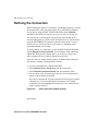
This chapter describes the preparations you should make before you start to
configure Digital DEC/EDI. In summary, you need to do the following:
• If Digital DEC/EDI is not already running, start it, as described in
Section Starting and Stopping Digital DEC/EDI on page 1-2.
• Use the SYSTEM account to give users access to Digital DEC/EDI, as
described in Section Giving Users Access to Digital DEC/EDI on page
1-3.
Note that you must use an account with the following privileges to do the
tasks described in this chapter:
• SYSPRV
• DETACH (only if starting up Digital DEC/EDI )
• TMPMBX
• NETMBX
If you are not already an authorized Digital DEC/EDI user, you must be
logged into the SYSTEM account.
When you grant Digital DEC/EDI access rights to a user who is already
logged in, that user must log out and back in again before attempting to use
the Digital DEC/EDI INTERCHANGE command. This is because Digital
DEC/EDI uses the system rights identifiers DECEDI$SUPERVISOR and
DECEDI$ADMINISTRATOR to control access to Digital DEC/EDI.
System rights identifiers are granted to a user only when logging in.
1-2 Starting and Stopping Digital DEC/EDI
Starting and Stopping Digital DEC/EDI
The Digital DEC/EDI management interface needs the Digital DEC/EDI
data server to be running. Thus, you must make sure that the data server is
running before you can start to configure your system. To find out if the
Digital DEC/EDI data server process is running, search through the output
from SHOW SYSTEM. For example:
$ SHOW SYSTEM /OUT=A.A
$ SEARCH A.A DECEDI
Look for the data server process, DECEDI$DS. If the process exists then
Digital DEC/EDI is running. If the process does not exist, you must start it
by starting DEC/EDI. Only FULL startup of Digital DEC/EDI is available.
This starts the Digital DEC/EDI data server and all of the Digital DEC/EDI
services if configured. Enter the following command:
$ @SYS$STARTUP:DECEDI$STARTUP
When you have finished configuring the Digital DEC/EDI Server, you need
to shut Digital DEC/EDI down and restart using the above startup
command, to start all the services you have specified in the course of
configuring the system.
Similar to startup, shutdown also can be done only in FULL mode. To
shutdown Digital DEC/EDI, Enter the following command.
$ @SYS$STARTUP:DECEDI$SHUTDOWN
When Digital DEC/EDI is running, you use the following command to enter
the management interface and gain access to the Digital DEC/EDI
commands:
$ INTERCHANGE
When you are using the management interface under the INTERCHANGE
command, you will not be notified if another user does a Digital DEC/EDI
system shutdown.
PREPARING TO CONFIGURE DIGITAL DEC/EDI
Giving Users Access to Digital DEC/EDI 1-3
Giving Users Access to Digital DEC/EDI
You have to register all users who are to have access to the Digital DEC/EDI
system, giving them the correct access rights to use the Digital DEC/EDI
management commands. The first time you register users (including
yourself), you do so by giving Digital DEC/EDI commands under the
account name SYSTEM, which does not have to be registered with Digital
DEC/EDI. You then need to register the following users:
• All users who are going to use Digital DEC/EDI management commands
for configuring or running the system.
• All user names under which local Application Client calls are going to
made for sending and receiving documents: that is, command line calls
or calls from application code, to a Digital DEC/EDI Client that is on the
same node as the Digital DEC/EDI Server.
Assign TRANS_ADMIN user rights (see below) to each local Application
Client.
You do not have to register remote Application Clients.
Before registering a user with Digital DEC/EDI, that user must first be
registered with the OpenVMS system. The user must already have an
OpenVMS Authorization Entry in SYS$SYSTEM:SYSUAF.DAT, granting
one of the following OpenVMS rights identifiers:
• DECEDI$ADMINISTRATOR — You can then register the user with
Digital DEC/EDI, giving administrator access rights.
• DECEDI$SUPERVISOR — You can then register the user with Digital
DEC/EDI, giving supervisor access rights.
You register a user with Digital DEC/EDI by using the Digital DEC/EDI
command ADD USER, assigning Digital DEC/EDI access rights. There are
two levels of Digital DEC/EDI access rights:
• Administrator access rights: TRANS_ADMIN or COMMS_ADMIN
• Supervisor access rights: SUPERVISOR
Administrator Access Rights
If you have administrator access rights, you are responsible for ensuring that
Digital DEC/EDI is in an operational state. You can use all the commands
PREPARING TO CONFIGURE DIGITAL DEC/EDI
1-4 Giving Users Access to Digital DEC/EDI
available from the management interface to control the services for which
you are responsible. Commands available to the administrator include those
that grant and revoke access to the Digital DEC/EDI system.
There must be at least one administrator for each of the Digital DEC/EDI
services. The need for extra administrators depends on the size and
complexity of your Digital DEC/EDI configuration.
In simple Digital DEC/EDI configurations you may not need additional
people to manage the services. In this case, the person responsible for
managing the rest of the computer system may also do the administration
tasks on Digital DEC/EDI. But, for large, distributed systems, you may need
more than person to look after Digital DEC/EDI.
Supervisor Access Rights
For each application that uses Digital DEC/EDI, someone must be
responsible for monitoring all documents processed by the application. This
person must have, as a minimum, supervisor access rights.
If you have supervisor access rights, you can monitor documents to see
whether or not they have been processed correctly. If a document fails while
being processed you can make Digital DEC/EDI reprocess the document,
but you do not have the necessary access rights to correct any errors that
occur within Digital DEC/EDI. When a problem occurs, you must report it
to the appropriate Digital DEC/EDI administrator.
Assigning Access Rights
Some Digital DEC/EDI commands are specific to a particular service and,
to use them, you must have the correct access right for that service. If you
are the only administrator for all the services, then you must have access
rights for every service.
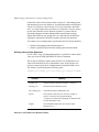
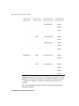
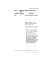
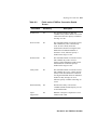
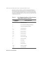
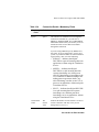
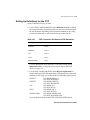
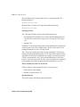
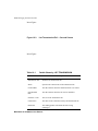
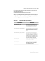
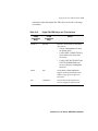
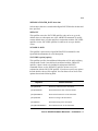
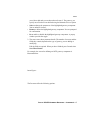
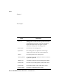
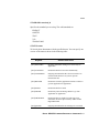
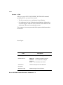
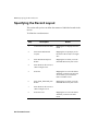
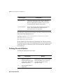
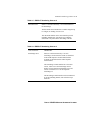
Table 1-1 describes the commands that control access to Digital DEC/EDI.
PREPARING TO CONFIGURE DIGITAL DEC/EDI
Giving Users Access to Digital DEC/EDI 1-5
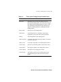
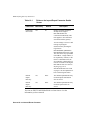
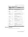
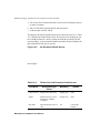
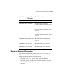
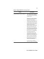
Table 1-1
Commands to Control Access to Digital DEC/EDI
Command
Description
ADD USER
Adds a new user to Digital DEC/EDI, with specified
access rights
LIST USER
Lists all Digital DEC/EDI users with their access rights
MODIFY USER
Modifies the access rights of an existing Digital DEC/EDI
user
REMOVE USER
Removes all access rights from the specified user
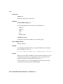
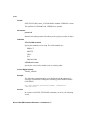
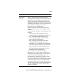
Use ADD USER to give access rights to a user. For example, to give
translation administrator and communications administrator access rights to
a user who has an OpenVMS account name of TIMG, enter:
EDI> ADD USER TIMG /RIGHTS=TRANS_ADMIN
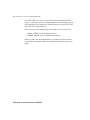
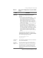
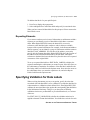
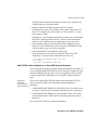
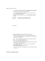
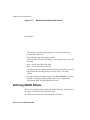
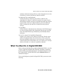
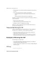
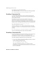
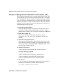
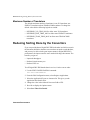
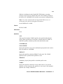
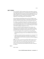
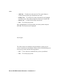
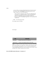
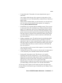
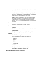
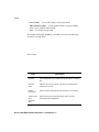
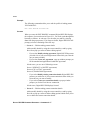
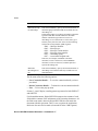
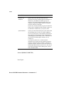
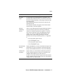
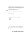
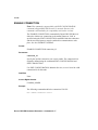
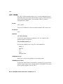
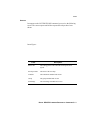
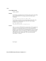
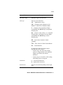
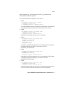
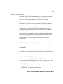
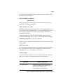
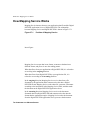
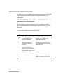
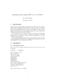
Figure 1-1
List User Screen
Insert Figure...
PREPARING TO CONFIGURE DIGITAL DEC/EDI
1-6 Giving Users Access to Digital DEC/EDI
Use LIST USER to see a list of users who can access Digital DEC/EDI.
Figure 1-1 shows the screen. By using qualifiers to this command, you can
select which users you want to list; for more details, see Digital DEC/EDI:
OpenVMS User Support Manual.
There are two types of administrator access rights, one for each service:
• TRANS_ADMIN, for the Translation Service
• COMMS_ADMIN, for the Communication Service
When you add a user as an administrator, you grant one or more of these
access rights. You change what a user can do by altering that user’s access
rights.
PREPARING TO CONFIGURE DIGITAL DEC/EDI
Chapter 2 Registering the Digital
DEC/EDI Services
This chapter describes how to specify the Digital DEC/EDI services that are
to run on the Digital DEC/EDI Server. You also need to tell the Server about
existing Client applications, Client nodes, Digital DEC/EDI Cockpit nodes,
and V1.3 Application site applications and nodes. This chapter has the
following sections:
• What you need to do — Section What You Must Do on page 2-2.
• Registering the services — Section Registering the Digital DEC/EDI
Services on page 2-2.
• Registering the applications — Section Registering the Applications on
page 2-6.
• Registering the Client nodes — Section Registering the Client Nodes on
page 2-7.
• Defining logical names — Section Defining Logicals in
DECEDI$SYLOGICALS.COM on page 2-9.
For many of the tasks in this chapter you need OpenVMS privileges. You
must have access to a privileged account, such as SYSTEM. As a minimum,
the account you use must have the OpenVMS privilege, SYSPRV.
Throughout this chapter there are examples of Digital DEC/EDI commands
that you use for specifying routing information, and of the screens that these
commands lead you to. You should refer to Digital DEC/EDI: OpenVMS
User Support Manual for a full specification of command formats and
screen fields.
2-2 What You Must Do
What You Must Do
The main tasks in routing documents and transmission files through the
Digital DEC/EDI Server are as follows:
1. Registering which services are available on the Server.
2. Registering the Application Client.
3. Registering which nodes the Digital DEC/EDI Clients are running on.
When you register a Digital DEC/EDI gateway, you also assign a
connection-id; this identifies a particular set of communications
characteristics, such as VAN login details, DTE addresses, record lengths,
and so on. You later specify this connection-id when setting up details of a
trading partner, so that outgoing documents destined for that trading partner
can be routed to the appropriate connection for transmission.
When you register each application, you have to assign an application-id;
this identifies a particular application, and its characteristics such as a
VMSmail address for the notification of problems. You later specify this
application-id when setting up details of a trading partner agreement, so that
incoming documents from the trading partner, which come under that
agreement, can be routed to the appropriate application on the appropriate
Client, for processing.
Registering the Digital DEC/EDI Services
You have to register all the Translation and Communication Services that
are going to run on the Digital DEC/EDI Server. You do not have to register
the Mapping Service, as this component is always present on the Digital
DEC/EDI Server.
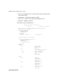
You register Digital DEC/EDI services by using the EDIT
CONFIGURATION command, and selecting the option Maintain Services.
When doing this, you must be logged on to the Server you are setting up.
For example, suppose the current node is called EDIVAX, and you want it to
run an X12 Translation Service and an X.400 gateway. You would set this
up as follows:
REGISTERING THE DIGITAL DEC/EDI SERVICES
Registering the Digital DEC/EDI Services 2-3
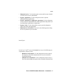
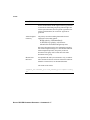
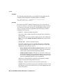
1. Enter the command EDIT CONFIGURATION.
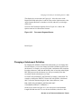
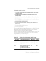
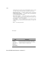
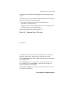
2. Move the cursor to the option Maintain Services, and press Select .You
then see the screen illustrated in Figure 2–1, showing current services.
3. Press Insert to add the first service.
4. In the pop-up window, specify the following:
Component: X12_TRANSLATOR
Then move the cursor to the Save button, and press Select .
5. Press Insert to add the second service.
Figure 2-1
Maintain Services Screen
6. In the pop-up window, specify the following:
Component: X400_GATEWAY
Connection ID: XCON
Then move the cursor to the Save button, and press Select .
REGISTERING THE DIGITAL DEC/EDI SERVICES
2-4 Registering the Digital DEC/EDI Services
7. When you have defined all the required services, exit from the EDIT
CONFIGURATION screens by using the Exit key.
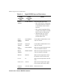
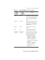
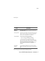
When you are using the EDIT CONFIGURATION option Maintain
Services , you can use the keys listed in Table 2–1 to select the action you
want to carry out.
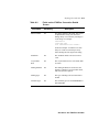
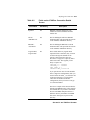
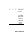
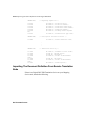
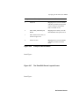
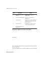
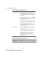
Table 2–1 Control Keys for Defining Services
Key
Insert
Description
You use this key to add a service to the Digital DEC/EDI Server.
On the Maintain Services screen, the cursor can be in any
position when you press Select . A pop-up window then invites
you to specify the service.
If you are adding a Communication Service, then you must also
specify a connection-id. This is simply an identifier that links the
service with other information you will define later. For more
detail, see Section Specifying Connection-ids on page 2-4 and
Section Connection-ids for VAN Connections on page 2-5.
Select
You use this key to select an item from a menu or list.
Remove
You use this key to remove a service from the list on the current
node. On the Maintain Services screen, move the cursor to the
service you want to remove, and press Remove . You are
prompted to confirm this choice. The Server cannot then use the
service, even if the software remains installed.
Specifying Connection-ids
When you send transmission files through a gateway you must provide
specific details about the connection you are setting up. For example, if you
send files through the X.400 gateway directly to a trading partner, and also
to a VAN for onward routing to other trading partners, then you will have
different sets of characteristics for the two connections.
Each time you add a Communications Service to the Digital DEC/EDI
system, you assign a connection-id; this is a maximum of six characters, and
REGISTERING THE DIGITAL DEC/EDI SERVICES
Registering the Digital DEC/EDI Services 2-5
provides a link between the service you are adding and other information
you later define.
You will reference the connection-id when defining a trading partner profile,
to identify the gateway and connection you are going to use when
exchanging documents with that partner. (You define the trading partner
profile by using the command EDIT PROFILE; this is described in a series
of later chapters, about setting up each type of Translation Service.)
You will also reference the connection-id when you come to define the
actual communications characteristics of that particular connection on the
gateway. (You define the connection characteristics by using the EDIT
CONFIGURATION option Maintain Connection Details; this is described
in a series of later chapters, about setting up each type of Communication
Service.)
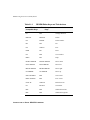
Connection-ids for VAN Connections
The various Digital DEC/EDI gateways allow you to exchange transmission
files with a trading partner, either by means of a direct connection, or over a
VAN. If you are using a VAN connection, then you must use one of the
following special connection-ids:
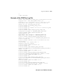
• GEIS — Connection to the EDI*EXPRESS VAN provided by GEIS
(through the Bisync gateway).
• MCDD — Connection to the EDI*NET VAN provided by BT-TYMNET
(through the Bisync gateway).
• EDIC — Connection to the ISTEL-EDICT VAN provided by AT&T
ISTEL (through the Bisync gateway).
• P_GEIS — Connection to the EDI*EXPRESS VAN provided by GEIS
(through the 3780Plus gateway).
• P_MCDD — Connection to the EDI*NET VAN provided by BTTYMNET (through the 3780Plus gateway).
• TRAX — Connection to the TRADANET VAN provided by INS
(through the X.25 gateway).
(The connection-id MCDD is for the historical reason that the VAN used to
be owned by McDonnell Douglas.)
REGISTERING THE DIGITAL DEC/EDI SERVICES
2-6 Registering the Applications
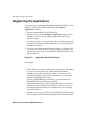
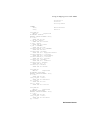
Registering the Applications
You need to register each application with the Digital DEC/EDI Server. You
do this by using the EDIT CONFIGURATION option Register
Applications, as follows:
1. Enter the command EDIT CONFIGURATION.
2. Move the cursor to the option Register Applications, and press Select .
You then see a list of currently registered applications; the list may
initially be empty.
3. Press Insert to register a new application. A pop-up window prompts you
to specify the application-id of the application you are registering; enter
the id and press Return .
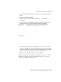
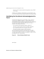
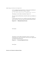
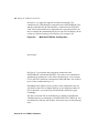
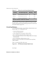
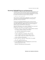
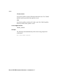
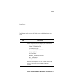
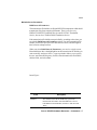
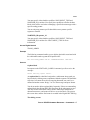
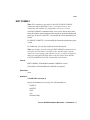
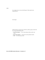
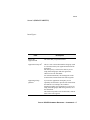
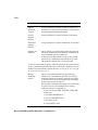
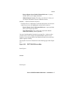
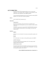
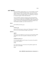
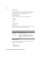
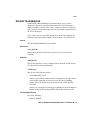
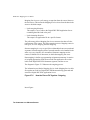
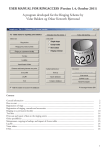
4. You see a screen similar to that illustrated in Figure 2–2. Edit the fields
as required. Some of the fields are only for recording information, and
have no effect on the behavior of Digital DEC/EDI. Other fields are more
than documentary:
Figure 2-2
Application Site Details Screen
Insert Figure...
• E Mail Address (see also next field). Specify the electronic mail address
of a contact. You can specify any valid OpenVMS mail address,
including a list of names separated by commas, or the name of a file
containing a distribution list of mail account names. If you specify the
filename of a distribution list, such as
@DUA1:[USER1]ERROR_NOTIFY.DIS, you must ensure that the
Digital DEC/EDI account has access to the file.
• E Mail Notification. Specify YES if Digital DEC/EDI is to send a mail
message to the above mail address(es) whenever it detects an error in
processing a document owned by the application site you are defining.
Specify NO otherwise.
• Ordered Converter. Specify YES if you want Digital DEC/EDI to assume
that all outgoing documents from the application have their data labels in
REGISTERING THE DIGITAL DEC/EDI SERVICES
Registering the Client Nodes 2-7
the correct order; that is, in the same order as the corresponding fields in
the definition of the document types. Specify NO otherwise.
Specifying YES means that it is the responsibility of the application to
ensure that a document does not fail conversion because of incorrect
ordering. On the other hand, conversion will take place much quicker,
and without such heavy load on virtual memory, since the converter does
not have to sort the document’s records; in the case of large documents,
the difference can be significant.
5. When you have finished editing the fields, press Do and select Save
These Site Details. Then exit from the EDIT CONFIGURATION
screens.
See Table 2–1 for details of the control keys you can use.
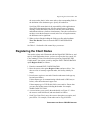
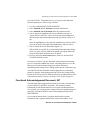
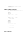
Registering the Client Nodes
You need to register each Client node with the Digital DEC/EDI Server, and
specify which applications it runs; you have to register the Server node, if it
is also running a Client. You also need to register any Digital DEC/EDI
Cockpit nodes. You register a node by using the EDIT CONFIGURATION
option Register Nodes, as follows:
1. Enter the command EDIT CONFIGURATION.
2. Move the cursor to the option Register Nodes, and press Select . You
then see a list of currently registered nodes; the list may initially be
empty.
3. Press Insert to register a new node. Enter the node name in the pop-up
box,and press Return.
If the transport type for communicating with the node is DECnet (see
below), enter the node name in upper case.
If the transport type is TCP/IP, this field is case-sensitive. Ensure that
you enter the full host name, including the domain: for example,
WARP1.DOM.XYF.COM
4. A screen invites you to specify the node details; see Figure 2–3. Move
the cursor to each field in turn, and enter details as follows:
• Node Type. Press Find ; move the cursor to the option you require; and
press Select . For example, Client nodes can be of type ALPHAREGISTERING THE DIGITAL DEC/EDI SERVICES
2-8 Registering the Client Nodes
AXP.VMS and Digital DEC/EDI Cockpit nodes (such as an 80386 PC
running MicroSoft Windows) can be of type 80X86.WIN.
• Transport Type. Press Find ; move the cursor to the option you require;
and press Select . For example, the transport type can be DECnet or
TCP/IP.
Figure 2-3
Register Node Screen
5. When you have specified the node details, press Do and select Save
These Node Details.
6. You now have to identify the applications running on the node (if it is a
Client node and not a Digital DEC/EDI Cockpit node). Select Register
Client Applications.
7. You see a list of currently registered applications for this node; see
Figure 2–4. The list may initially be empty.
8. Press Insert to register a new application. Enter the application-id in the
pop-up box, and press Return .
9. The application-id is then added to the list.
When you have registered all the nodes and their applications in this way,
exit from the EDIT CONFIGURATION screens.
REGISTERING THE DIGITAL DEC/EDI SERVICES
Defining Logicals in DECEDI$SYLOGICALS.COM 2-9
Figure 2-4
Register Client Application Screen
See Table 2–1 for details of the control keys you can use.
Defining Logicals in
DECEDI$SYLOGICALS.COM
In the directory SYS$MANAGER there is a command file
DECEDI$SYLOGICALS.COM which Digital DEC/EDI runs automatically
on every startup. The file consists, essentially, of a sequence of DEFINE
statements which set up logical names in a table called
DECEDI$LOGICAL_NAMES. The table is reserved for use by Digital
DEC/EDI.
You may want to add further logical names for your own purposes, by
editing the file DECEDI$SYLOGICALS.COM. Any changes you make to
the file will take effect the next time Digital DEC/EDI starts up, and are
permanent. Use any one of the usual editors, and imitate the format of the
statements already present. Because the file is stored in a system directory,
you must have the OpenVMS privilege SYSPRV to edit it. You get this
privilege, for example, when logged into the SYSTEM account.
REGISTERING THE DIGITAL DEC/EDI SERVICES
2-10 Defining Logicals in DECEDI$SYLOGICALS.COM
For example, you can define logical names to specify mail addresses for the
notification of gateway disconnections, as described in the gateway chapters
of this book. Or you can specify that you want the error log to contain only
messages of level WARNING and greater (ie not information messages), by
editing the following line in DECEDI$SYLOGICALS.COM:
$ DECEDI$DEFINE DECEDI$LOG_SEVERITY "WAR"
The symbols DECEDI$DEFINE and DECEDI$DEASSIGN represent
DEFINE and DEASSIGN statements. The symbols are defined at the start
of DECEDI$SYLOGICALS.COM, as follows:
$ DECEDI$DEFINE := DEFINE /USER /NOLOG
/TABLE=DECEDI$LOGICAL_NAMES
$ DECEDI$DEASSIGN := DEASSIGN /USER /NOLOG
/TABLE=DECEDI$LOGICAL_NAMES
If you want a logical name to take effect immediately, without restarting
Digital DEC/EDI, then you can define the name directly in table
DECEDI$LOGICAL_NAMES. (You also edit the command file if you want
the change to be permanent; but not if you do not want the change to be
permanent.) For example, you might give the following command:
$ DECEDI$DEFINE DECEDI$LOG_SEVERITY "WAR"
REGISTERING THE DIGITAL DEC/EDI SERVICES
Chapter 3 Configuring for Application
to Application
Routing
Setting Up an Application to Application System
You can use Digital DEC/EDI to exchange documents internally between
two applications in your Digital DEC/EDI system; this is called application
to application, or sometimes site-to-site, routing. The applications can be
on two separate nodes, or they can be on the same node.
Note that no configuration is performed on Digital DEC/EDI application
clients, this is performed on the server.
Configuring the DEC/EDI V4 clients
All configuration for application to application routing for Digital DEC/EDI
application clients is done on the Server, you must use an account with
translation administrator access right.
Log in to the Server node and enter the following details (note that unless
the client is on the server node the server will be a different node to the
client):
• Use the EDIT CONFIGURATION option Register Nodes to register
both the nodes and their applications.
• Use the EDIT CONFIGURATION option Register Site-site
Agreements to tell the system that all outbound documents with the
specified application, partner and document combination are to be sent
site-to-site instead of treated as normal documents.
It is not necessary to perform this configuration for inbound site-to-site
documents. However if both applications send and receive documents, you
must specify the routing of outgoing documents in both directions.
3-2 Setting Up an Application to Application System
Example of a Site-to-Site System
In the example shown in Figure 4–1, application LOCAL-SEND, is running
on node GREEN which is a Digital DEC/EDI V4 client running on an Alpha
AXP with OpenVMS. This is sending documents (invoices) to application
LOCAL_GET running on node BLUE. The Digital DEC/EDI server is node
BLACK.
Figure 3-1
Example of a Site-to-Site System
Configuring the server - node BLACK
CONFIGURING FOR APPLICATION TO APPLICATION ROUTING
Setting Up an Application to Application System 3-3
Log on to the server node using an account with translation administrator
access right and enter the following details:
1. Use the EDIT CONFIGURATION option Register Nodes to insert the
following information for node GREEN:
Node: GREEN
Remote Node: YES
Node Type: ALPHA-AXP.VMS
Transport Type: TCP-IP
2. Save these details and select the Register Client Applications option.
Insert the following information:
Application ID: LOCAL-SEND
3. Insert the following information for node BLUE:
Node: BLUE
Remote Node: NO
Node Type: ALPHA.VMS
Transport Type: TCP-IP
4. Save these details and select the Register Client Applications option.
Insert the following information:
Application ID: LOCAL-GET
5. Use the EDIT CONFIGURATION option Register Site To Site
Agreements to insert the following information:
Application ID: LOCAL-SEND
Partner ID: LOCAL-GET
Document Type: INVOICE
The document type is optional, if all documents from the specified
application should be routed site-to-site.
6. Use the BUILD CACHE /PROFILE command to build the profile with
this changed configuration.
7. Profile cache need to be replaced with the REPLACE
CACHE/PROFILE command.
CONFIGURING FOR APPLICATION TO APPLICATION ROUTING
Chapter 4 Setting up the Translation
Services Tables
This chapter describes how to set up the tables used by the Translation
Service. The Translation Service uses these tables when converting
documents between the internal format known to the application programs,
and the external format in which documents are exchanged with trading
partners.
Because of distinct variations in EDI syntax, Digital DEC/EDI has three
different translation services, which may be configured independently.
• EDIFACT/ODETTE Translation Service
This handles EDIFACT and ODETTE messages, and messages based on
those standards that conform to ISO 9735 and EDIFACT enveloping
rules.
• TRADACOMS Translation Service
This handles TRADACOMS messages, and messages based on those
enveloping rules.
• X12/TDCC Translation Service
This handles ANSI X12 and TDCC (UCS/WINS) messages, and
messages based on those standards that conform to its enveloping rules.
These are all described in this chapter. Where examples are given that are
specific to one standard, there is usually an equivalent for the other
standards.
What You Must Do
To configure the Translation Service so that you can exchange documents
with trading partners, you need to carry out the following tasks:
4-2 What You Must Do
• Identify the documents you want to exchange; see Section Identifying the
Document to Exchange on page 4-3
Digital supplies a number of standard documents; you do not need to
make any changes to these documents before sending them to a trading
partner.
• Decide how you are going to update the cache in memory when you
define new trading partner profiles and document tables; see Section
Caching Profile and Document Definitions on page 4-4
When you define new profiles and tables, you can either wait until the
next restart of Digital DEC/EDI to take effect, or you can explicitly
update the memory cache immediately.
• Create a trading partner agreement profile; see Section Creating a
Trading Partner Profile on page 4-6
The trading partner agreement profile links together the trading partner,
the documents you exchange with them, and the applications that
produce outgoing, or process incoming, documents.
• Identify which Functional Acknowledgement document, if any, to send.
For X12/TDCC this would be a 997 or 999 document. For EDIFACT,
this would be a CONTRL message. This functionality is not provided for
TRADACOMS.
• Define the data labels used to identify individual subelements of the
document; see Section Creating Data Labels on page 4-34
Data labels provide the link between the business application and the
data in the document to be exchanged.
• Specify the validation to be applied, inbound and outbound, for each data
label on a document; see Section Specifying Validation for Data Labels
on page 4-41
If you do not explicitly specify validation for documents, Digital
DEC/EDI uses the description of the subelement in the subelement
dictionary for validation purposes. Alternatively, you can explicitly
associate validation criteria with each data label.
• Schedule the Transmission File Builder (TFB); see Section Scheduling
the Transmission File Builder on page 4-43
The TFB assembles converted documents into transmission files; you
must specify when to start the TFB, and the frequency at which it runs.
There is no Transmission File Builder for the TRADACOMS standard.
SETTING UP THE TRANSLATION SERVICES TABLES
Identifying the Document to Exchange 4-3
• Customize documents, in agreement with all trading partners, if required;
see Section Changing a Document for All Trading Partners on page 4-44
This is an optional task you can carry out after the above tasks, if you
need to modify the structure of one or more documents for use with all
trading partners.
• Customize documents, in agreement with a specific trading partner, if
required; see Section Changing a Document for a Specific Trading
Partner on page 4-48
This is an optional task you can carry out after the above tasks, if you
need to modify the structure of one or more documents for use with a
specific trading partner.
• Customize documents, in agreement with a specific trading group, if
required. This option is only available for the TRADACOMS standard.
This is an optional task you can carry out after the above tasks, if you
need to modify the structure of one or more documents for use with a
specific trading group.
In the course of carrying out these tasks, you need to use a number of Digital
DEC/EDI commands.
Refer to Section Mapping Screen Fields to External Document Fields on
page 4-54, for an illustration of the mapping between the values that you
specifiy on-screen when setting up the Translation Service, and the location
of those values in the envelope segments of the external files exchanged
with trading partners. This may help you to understand the way in which
Digital DEC/EDI handles and routes documents on the basis of these values,
and the location of those values in the enveloping segments of the external
files.
Identifying the Document to Exchange
With your Digital DEC/EDI system, Digital supplies a number of standard
document definitions which you can use for exchanging documents with
trading partners. You do not need to change these document definitions in
any way before you use them. (You can also get more standard document
definitions from Digital’s Standards Update Service. )
Use the command LIST TABLES to display all Digital-supplied documents.
You can select specific documents to display, and different views of this
SETTING UP THE TRANSLATION SERVICES TABLES
4-4 Caching Profile and Document Definitions
information, by using various combinations of qualifiers. You should also
refer to the descriptions of each document to see which ones meet your
business requirements.
On the other hand, you and your trading partner may agree to exchange
modified or totally new documents. See Section Changing a Document for
All Trading Partners on page 4-44 and Section Changing a Document for a
Specific Trading Partner on page 4-48 for how to change a document, either
for use with all trading partners, or for use with one specific trading partner.
Caching Profile and Document Definitions
For performance reasons, Digital DEC/EDI keeps trading partner profile
definitions and document table definitions as caches in memory, while it is
running. There is one profile cache, and one document table cache for each
standard being used. When you set up new trading partner profiles and
document tables, the definitions are written to disk, but do not take effect
until the cache in memory is updated.
If there are any warnings (soft errors) during the build process a warning
message will indicate that a file has been created. the name of this file is
PCC_REPORT.DAT and it will be created in the current working directory
of the user that issued the BUILD CACHE command. This file contains
information about why certain profiles could not be built; either due to
missing data or invalid data.
To bring new profile definitions into effect, you must ensure that whenever
you update a definition by using one of the commands:
EDIT PROFILE
EDIT TABLES (only the Trading Document screen)
EDIT SITE
EDIT FORMAT
EDIT CONFIGURATION Register Applications
EDIT CONFIGURATION Register Nodes
EDIT CONFIGURATION Maintain List Of Standards
EDIT CONFIGURATION Site-To-Site
EDIT TABLES (only the Trading Document screen)
SETTING UP THE TRANSLATION SERVICES TABLES
Caching Profile and Document Definitions 4-5
that you update the profile cache by using the following commands:
EDI> BUILD CACHE /PROFILE
This builds the profile definitions into a cache on disk. If Digital DEC/EDI
is running live while this is taking place, there may be a degrading of
document throughput.
EDI> REPLACE CACHE /PROFILE
This loads the built cache from disk into memory; Digital DEC/EDI uses the
new cache for the first document it processes after the load is complete.
Instead of using this command, you can wait until the next time that Digital
DEC/EDI is shutdown and restarted; the current built cache is then loaded
into memory.
To bring new document table definitions into effect, you must ensure that
whenever you update a definition by using one of the commands:
EDIT TABLES
EDIT SEGMENT_DICTIONARY
EDIT ELEMENT_DICTIONARY
EDIT SUB_ELEMENT_DICTIONARY
EDIT CODES
EDIT DATA_LABELS
EDIT ENVELOPE (X12/TDCC only)
EDIT VALUE_VALIDATION
that you update the document table cache by using the following command:
EDI> REPLACE CACHE /TABLE /ALL
This loads the built cache from disk into memory; Digital DEC/EDI uses the
new cache for the first document it processes after the load is complete.
Instead of using this command, you can wait until the next time that Digital
DEC/EDI is shutdown and restarted; the current built cache is then loaded
into memory.
(You don’t need to first use the command BUILD CACHE /TABLE /ALL
because document table caches are built on disk automatically on first
Digital DEC/EDI system startup.)
SETTING UP THE TRANSLATION SERVICES TABLES
4-6 Creating a Trading Partner Profile
Note that the EDIT TABLES Trading Document screen appears in both
groups of commands listed above. In this instance, both the profile cache
and the document table cache need updating for the new definitions to take
effect. Both caches also need to be updated with either the EDIT
ENVELOPE or EDIT FORMAT (EDIT CONFIGURATION Maintain List
of Standards).
Creating a Trading Partner Profile
The trading partner agreement profile links together the trading partner, the
documents you exchange with them, and the applications that produce or
process the documents. Each trading partner must be assigned a unique id
within your Digital DEC/EDI system. For each trading partner with whom
you exchange documents, you must enter information about the trading
partner, and about the documents you exchange. This information is
contained in a profile.
Use the EDIT PROFILE command to enter a trading partner profile. For
example, to enter information about a trading partner called XY-FOODSINC, you:
• Enter the command:
EDI> EDIT PROFILE XY-FOODS-INC
• This displays the Trading Partner Details screen, shown in Figure 4-1.
Enter (or edit) the trading partner details; Table 4-1 describes the fields.
• When you have finished, continue as described below.
Figure 4-1
Trading Partner Details Screen
Insert Figure...
SETTING UP THE TRANSLATION SERVICES TABLES
Creating a Trading Partner Profile 4-7
Table 4-1
Field
Fields on the Trading Partner Details Screen
Description
Partner ID
Mandatory field. Specify the id that you use to
identify this trading partner. You do not need to agree
this name with the trading partner; the name is used
only internally by Digital DEC/EDI, and does not
appear in external documents exchanged with the
trading partner.
Partner Name
The full name of the trading partner.
Organization
If the trading partner is a department within a larger
organization, enter the full name of that organization.
Address
The mailing address of the trading partner.
Address Qualifier
An optional value used to qualify the address, for instance,
a particular department.
Address Code
An optional, coded value, for the trading partner address.
Contact Name
The name of your trading partner’s primary EDI contact.
Contact Phone
The telephone number of the trading partner contact.
Contact Address
The address of the trading partner contact.
Connection ID
This provides a link between a trading partner and the
communications gateway that will be used with that
partner.
SETTING UP THE TRANSLATION SERVICES TABLES
4-8 Creating a Trading Partner Profile
Table 4-1
Fields on the Trading Partner Details Screen
Field
Description
If you are using a gateway to a VAN, then you must use
one of the following connection-ids to identify the VAN:
• P_GEIS — Connection to the EDI*EXPRESS
VAN provided by GEIS (through the 3780Plus
gateway).
• P_MCDD — Connection to the EDI*NET VAN
provided by BT-TYMNET (through the 3780Plus
gateway).
• TRAX — Connection to the TRADANET VAN
provided by INS (through the X.25 gateway).
Otherwise you are not restricted in your choice of
connnection-id.
SETTING UP THE TRANSLATION SERVICES TABLES
Creating a Trading Partner Profile 4-9
Table 4-1
Field
Acknowledgeme
nt Flag
Fields on the Trading Partner Details Screen
Description
A mandatory field used to specify whether or not
functional acknowledgements are to be used for this
trading partner. This field must be set to one of the
following:
• NO -- No functional acknowledgements will be
accepted or generated.
• YES -- Functional acknowledgements will be
generated and accepted. When creating an
outbound functional acknowledgement, only
segments containing the general information about
the functional group and information about the
documents that failed is generated. If a document
was successfully translated, then no segment for
that document is generated. If no documents
failed, then only the general information about the
functional group will be sent.
• DOC -- Functional acknowledgements will be
generated and accepted. When creating an
outbound functional acknowledgement, segments
are generated for each document in the functional
group, whether or not the documents failed or
translated successfully. General information about
the functional group will also be sent.
Acknowledgeme
nt Priority
This value determines if outgoing Functional
Acknowledgement (FA) documents will be treated as high
priority or as normal documents. High priority FA
documents will be processed immediately and normal FA
documents will be processed at the next TFB build and
VAN connect.
0 = High Priority
1 = Normal
You must now define a trading partner connection. This identifies the
connection-id you will use for exchanging transmission files with the
trading partner, and defines details about the transmission files. The
connection-id points to a particular gateway (which you assigned in Chapter
SETTING UP THE TRANSLATION SERVICES TABLES
4-10 Creating a Trading Partner Profile
2), and points to a set of communications characteristics (which you assign
in Chapter 7).
Figure 4-2
Trading Partner Connection Details Screen
Insert Figure...
For one trading partner, you can identify several connection-ids; conversely,
you can identify the same connection-id for several trading partners. The
first connection-id you identify serves as a default for all document types
that you exchange with the trading partner; you can override this for
particular document types when you define the document details (see
below). You create a trading partner connection as follows:
1. On the Trading Partner Details Screen, press Do to display the Options
menu.
2. Select Create New Connection Details.
3. In the pop-up box, enter the connection-id you want to use.
4. You see the Trading Partner Connection Details screen, shown in Figure
4-2. Enter the connection details. (You also use the same screens for
editing details of an existing connection when Modify Connection
Details is selected.) Table 4-2 describes the fields on the screen. Refer to
Section Defining Trading Partner-Specific Parameters on page 11-13 for
more details of the Connection Specific Data Field.
Table 4-2
Fields on the Trading Partner Connection Details
Screen
Field
Partner ID
Connection ID
Description
The values that you specified earlier.
SETTING UP THE TRANSLATION SERVICES TABLES
Creating a Trading Partner Profile 4-11
Table 4-2
Field
Connection
Specific Data
Fields on the Trading Partner Connection Details
Screen
Description
You can use this optional field for data relevant to the
connection used to exchange documents under this
agreement.
For OFTP connections, this field has two uses:
• You can specify the final OFTP destination (OFTP
ID) for transmission files, if the destination is
different from the OFTP ID that you set up using
EDIT CONFIGURATION. This is useful if you
want to send documents to different trading partners
within the same company.
• You can specify an OFTP Virtual File Name for all
transmission files sent to a trading partner. By
default, the OFTP gateway assigns an OFTP Virtual
File Name consisting of a timestamp to every file.
To override this default, enter the OFTP Virtual File
Name in this field. All files sent to this trading
partner then have the OFTP Virtual File Name you
specify.
To specify both values in this single field, first enter the
OFTP ID followed by a delimiter of ‘‘\’’ and then enter the
default OFTP Virtual File Name. For example, you could put
any of the following strings into this field:
oftp-id\virtual-file-name
rec_len\sfid_user
orig_oftp_id
Transmission
File Size
The maximum size (in Kilobytes) allowed for a transmission
file sent to this trading partner.
Maximum
Documents Per
Group
This field is mandatory. Specify the maximum number of
documents that may be bundled into one functional group.
If functional groups are not being used under a particular
agreement (see Table 4-3), then this field determines the
number of document instances that may be bundled into an
interchange set.
SETTING UP THE TRANSLATION SERVICES TABLES
4-12 Creating a Trading Partner Profile
Table 4-2
Fields on the Trading Partner Connection Details
Screen
Field
Maximum
Groups Per
Interchange
Description
This field is mandatory. Specify the maximum number of
functional groups which the TFB can assemble into one
interchange set.
If functional groups are not being used under a particular
agreement then this field determines the maximum number
of document types that can occur in an interchange set: two
documents are of the same type if and only if they have the
same values for the following fields in the message header
(UNH) segment:
S009
0065
0052
0054
0051
0057
—
—
—
—
—
—
Message identifier
Message type
Message version number
Message release number
controlling agency
Association-assigned code
Therefore, for example, an INVOIC document, version 2
release 901, and an ORDERS document, version 2 release
901, would be placed in separate interchange sets.
Maximum
Interchanges Per
File
This field is mandatory. Specify the maximum number of
interchange sets which the TFB may assemble into one
transmission file.
You must now define a trading partner agreement. This identifies an
application you will use for exchanging documents with the trading partner,
and defines details about the way documents will be exchanged. For one set
of trading partner details, you can have several different trading partner
agreements. You create a trading partner agreement as follows:
SETTING UP THE TRANSLATION SERVICES TABLES
Creating a Trading Partner Profile 4-13
1. On the Trading Partner Details screen, press Do to display the Options
menu.
2. Select Create New Agreement.
3. In the pop-up box, select the the standard you use to exchange
documents.
4. In the pop-up box, enter the application-id of the business application
that will produce or process documents under this agreement.
Figure 4-3
Trading Partner Agreement Details Screen
Insert Figure...
5. You see the first Trading Partner Agreement Details screen, shown in
Figure 4-3. On this, and a second and third screen, enter the agreement
details. (You also use the same screens for editing details of an existing
agreement.) Table 4-3 describes the fields on the three screens.
6. When you have finished, continue as described below.
Note: You should type a trading partner agreement in upper case. This is
mandatory for details relating to incoming documents, in either a unidirectional or bi-directional agreement.
SETTING UP THE TRANSLATION SERVICES TABLES
4-14 Creating a Trading Partner Profile
Table 4-3
Fields on the Trading Partner Agreement Details
Screens
Field
Description
Partner ID
Application ID
The values that you specified earlier.
Sender ID
(TRADACOMS)
This field is optional. It identifies your
organization. Specify a name or code that has
been agreed with your trading partner, typically
your ANA number.
If this agreement uses a TRADANET connection,
then the value you specify in this field must be the
same value you assign to the ANA number field,
when you define the connection. You define the
connection by using the EDIT
CONFIGURATION option Maintain
Connection Details. If the values are not the
same, TRADANET will reject the transmission as
a ‘‘Multi User Session’’.
If this agreement uses the OFTP Gateway, then
the value must be your OFTP id.
Sender Name
(TRADACOMS)
A textual name for your organiztion. This
optionally adds information to the previous field,
and can also be used for routing documents. You
must agree this name with the trading partner.
The value must be in uppercase.
Recipient ID
(TRADACOMS)
This field is optional. It identifies your trading
partner’s organization. Specify a name or code
that has been agreed with your trading partner,
typically your partner’s ANA number.
When using the OFTP Gateway, you must specify
your trading partner’s OFTP ID.
SETTING UP THE TRANSLATION SERVICES TABLES
Creating a Trading Partner Profile 4-15
Table 4-3
Fields on the Trading Partner Agreement Details
Screens
Field
Description
Recipient Name
(TRADACOMS)
A textual name for the trading partner’s
organization. This optionally adds information to
the previous field, and can also be used for
routing documents. You must agree this name
with the trading partner.
Application Group ID
This is a code or name that identifies the group
(such as a division) within your organization that
runs the application.
You must specify a value for this field if you are
using functional groups under this agreement;
otherwise leave the field blank. For X12/TDCC
you must always specify a value for this field.
Application Group
Qualifier
If you use the Application Group ID, you can
optionally use this field to provide more detail
about the identifier. For example, this could be a
department within your organization. If you are
not using functional groups under this agreement,
leave this field blank.
SETTING UP THE TRANSLATION SERVICES TABLES
4-16 Creating a Trading Partner Profile
Table 4-3
Fields on the Trading Partner Agreement Details
Screens
Field
Application Interchange ID
Description
This field is mandatory. It identifies your
organization. Specify a name or code that has
been agreed with your trading partner: typically
your ANA number when using TRADANET.
If this agreement uses a TRADANET connection,
then the value you specify in this field must be the
same value you assign to the ANA Number field,
when you define the connection. You define the
connection by using the EDIT
CONFIGURATION option Maintain
Connection Details. If the values are not the
same, TRADANET will reject the transmission as
a ‘‘Multi User Session’’.
If this agreement uses the OFTP Gateway, then
the value must be your OFTP id.
When exchanging TDCC documents and using
the GS/GE segments as the interchange envelope,
leave this field blank. Also ensure the records in
EDIT ENVELOPE and EDIT FORMAT
correspond to your use of the GS/GE segments
Application Interchange
Qualifier
Used if the identity of your organization is coded,
rather than named.
Application Interchange
Route
Specifies the address for reverse routing of
documents back to your Digital DEC/EDI system.
Partner Group ID
This is a code or name that identifies the group
(such as a division) within your trading partner’s
organization that runs the application. You must
specify a value for this field if you are using
functional groups under this agreement; otherwise
leave this field blank. For X12/TDCC you must
specify a value for this field.
SETTING UP THE TRANSLATION SERVICES TABLES
Creating a Trading Partner Profile 4-17
Table 4-3
Fields on the Trading Partner Agreement Details
Screens
Field
Description
Partner Group Qualifier
If you use the Partner Group ID, you can use this
field to provide more detail about the identifier.
For example, this could be a department within
your trading partner’s organization. If you are not
using functional groups under this agreement,
leave this field blank.
Partner Interchange ID
This field is mandatory. It identifies your trading
partner’s organization. Specify a name or code
that has been agreed with your trading partner:
typically your partner’s ANA number when using
TRADANET.
When using the OFTP Gateway, this must match
your trading partner’s OFTP ID.
When exchanging TDCC documents and using
the GS/GE segments as the interchange envelope,
leave this field blank. Also ensure the records in
EDIT ENVELOPE and EDIT FORMAT
correspond to your use of the GS/GE segments.
Partner Interchange
Qualifier
Used if the identity of the trading partner is
coded, rather than named. Used in conjunction
with the Appplication Interchange ID if your
organization uses a code name.
Processing Priority Code
Indicates the priority of documents under this
agreement. Enter 0 for normal processing, 1 for
priority processing.
Partner Interchange Route
Identifies onward routing for the document within
the trading partner’s EDI system.
SETTING UP THE TRANSLATION SERVICES TABLES
4-18 Creating a Trading Partner Profile
Table 4-3
Fields on the Trading Partner Agreement Details
Screens
Field
Description
Use Translators on Inbound
The default value is YES. This value can be used
in conjunction with the Syntax field in EDIT
CONFIGURATION Maintain Connection Details
screen when its value is MIXED. See the
appropriate gateway chapter for a description of
the Syntax field. The gateway is the one
configured for the trading partner profile.
Decimal Notation
Character
An agreed character to represent the decimal
point in a numeric value. The separators and
terminators in this field and the following fields
should all be distinct.
If you are using the 3780Plus gateway under this
agreement, then you should not use any of the
following hexadecimal values in this group of
fields, as the protocol emulator will interpret them
as control characters: 01, 02, 03, 05, 10, 15, 19,
1D, 1E, 26, 27, 2D, 30, 32, 37, 55, 7C
Segment Terminator
Character
An agreed character to indicate the end of a
segment in a document.
Element Separator
Character
An agreed character to separate elements in a
document.
Sub-Element Separator
Character
An agreed character to separate subelements in a
document.
Release Character
A prefix character which allows the above
terminator and separator characters to be used
literally in external document text. For example,
%+ could be used as a symbol for + in document
text.
SETTING UP THE TRANSLATION SERVICES TABLES
Creating a Trading Partner Profile 4-19
Table 4-3
Fields on the Trading Partner Agreement Details
Screens
Field
Character Set Validation
Description
Specify YES if you want documents under this
agreement to be fully validated against the
character set laid down by the X12 standard;
specify NO otherwise.
In either case, the data elements of types N, Nn,
DT and TM is always validated; the data elements
of types AN, CH and ID is validated only if you
specify YES.
Functional Group Used
Indicates whether or not Functional groups are
used.
SETTING UP THE TRANSLATION SERVICES TABLES
4-20 Creating a Trading Partner Profile
Table 4-3
Fields on the Trading Partner Agreement Details
Screens
Field
Message Numbering
Scheme
Description
This is a code indicating which message
numbering scheme is to be used under the
agreement. The message numbering schemes are
defined by particular user groups, or classes of
users, and you must agree with your trading
partner which scheme you will use.
For EDIFACT/ODETTE documents, the possible
values of this field are given below.
0. For EDIFICE users.
1. For ODETTE and CEFIC users.
2. For EurOSInet users.
3. For TRADANET users.
4. For LIMNET users.
5. For SMMT (ODETTE) users.
6. For UPU-ETSG users.
For X12/TDCC documents, the possible
values of this field are given below: for a full
definition of the message numbering
schemes, see Digital DEC/EDI: OpenVMS
User Support Manual.
0. For Air, Ocean, DIDX, EIDX and AIAG
users.
1. For Motor and Rail users.
2. For UCS and WINS users.
SETTING UP THE TRANSLATION SERVICES TABLES
Creating a Trading Partner Profile 4-21
Table 4-3
Fields on the Trading Partner Agreement Details
Screens
Field
Description
3. For TALC users.
4. For CPG users.
5. For FASLINC users.
For TRADACOMS documents, the possible
values of this field are given below: for a full
definition of the message numbering schemes, see
Digital DEC/EDI: OpenVMS User Support
Manual.
0. For no specific class of users.
1. For TRADANET users.
2. For no specific class of users.
3. For TRADANET users.
Processing Priority Code
Indicates the priority of documents under this
agreement. Enter 0 for normal processing, 1 for
priority processing.
Reconciliation Message
(TRADACOMS)
Specify ENABLED if you want reconciliation
messages to be generated at the end of a
transmission, under this agreement; specify either
DISABLED otherwise. This field is mandatory.
SETTING UP THE TRANSLATION SERVICES TABLES
4-22 Creating a Trading Partner Profile
Table 4-3
Fields on the Trading Partner Agreement Details
Screens
Field
Syntax Identifier
Description
You may use this field to identify the syntax
under which the interchange sets are built: for
example, EDIFACT level A. This is a fourcharacter field, the first three characters being
upper-case letters identifying the controlling
agency (for example, UNO = UN/ECE), and the
last character identifying the character set (for
example, A).
The value is used in the interchange header UNB
segment, element S001, subelement 0001.
Authentication Code
This and the following fields appear twice on the
screen: once for outgoing documents and once for
incoming documents.
This field is the password to your trading
partner’s EDI system, or the third-party network
that will forward your transactions. It must be
agreed with your trading partner or, where
applicable, with the third-party network.
Authentication Qualifier
This can be used to qualify the trading partner’s
authentication code (or password). If used, you
must agree the value with your trading partner.
SETTING UP THE TRANSLATION SERVICES TABLES
Creating a Trading Partner Profile 4-23
Table 4-3
Fields on the Trading Partner Agreement Details
Screens
Field
Application Reference
Description
This is an optional field; the value must be in
uppercase. The value is used as a message-id in
the interchange header segment, if the
transmission file contains only one message-type.
If you specify the value $MESSAGE-TYPE, then
the appropriate message-type code from the ANA
code list will be used.
If this agreement uses a TRADANET connection,
then specify the value $MESSAGE-TYPE.
If you leave this field blank, then the user
reference passed by the sending application on its
call of DECEDI$START_SEND will be used.
Application Password
An optional password to the trading partner’s
division, department or sectional system, if
required.
Communications
Agreement Reference
This identifies the type of communication
agreement controlling the interchange, for
example, Customs or ECE agreement. If used,
must be agreed with the trading partner.
Authentication Code (X12)
This and the following fields appear twice on the
screen: once for outgoing documents and once for
incoming documents.
This mandatory field is the password to your
trading partner’s EDI system, or the third-party
network that will forward your transactions. It
must be agreed with your trading partner or,
where applicable, with the third-party network.
Authentication Qualifier
(X12)
This can be used to qualify the trading partner’s
authentication code (or password). If used, you
must agree the value with your trading partner.
SETTING UP THE TRANSLATION SERVICES TABLES
4-24 Creating a Trading Partner Profile
Table 4-3
Fields on the Trading Partner Agreement Details
Screens
Field
Description
Security Code (X12)
This identifies the security information about the
sender, or the data in a transmission file. You
must agree this with your trading partner, and you
must supply a value.
Security Qualifier (X12)
This coded qualifier identifies the type of
information in the Security Code. You must agree
this with your trading partner, and you must
supply a value.
Having defined the trading partner agreement, you must identify what
document types you want to exchange. For one trading partner agreement,
you can have several different document types. You identify the document
types as follows:
1. On the Trading Partner Agreement Details screen, press Do to display
the Options menu.
2. Select Create New Document Type.
3. In the pop-up box, specify an internal name for the document type. You
can choose any name to represent a document type within your
organization, and you map this onto the external document type you are
exchanging, on the next screen.
4. You then see the Document Details screen, shown in Figure 4-4. On this,
and a second screen, enter the document details; Table 4-4 explains the
screen fields.
5. When you have finished, the trading partner is completely defined. Exit
from the EDIT PROFILE screens.
SETTING UP THE TRANSLATION SERVICES TABLES
Creating a Trading Partner Profile 4-25
Figure 4-4
Document Details Screen
Insert Figure...
Table 4-4
Fields on the Document Details Screen
Field
Description
Partner ID
Application ID
Document Type
Values that you specified earlier.
External Standard
External Document
The standard, version and external document type onto
which the internal document type maps. The EDIFACT
standard requires you to enter six alphabetic characters
for the external document type.
Test Indicator
LIVE — Indicates that this document contains real
data to be sent to the trading partner
PARTNER_TEST — Indicates that this is a test
document to be converted and sent to the trading
partner
TRANSLATOR_TEST — Indicates that the document
is converted, but not sent to the trading partner
SETTING UP THE TRANSLATION SERVICES TABLES
4-26 Creating a Trading Partner Profile
Table 4-4
Fields on the Document Details Screen
Field
Description
Direction Indicator
INCOMING — Only incoming documents are
transmitted
OUTGOING — Only outgoing documents are being
transmitted
BIDIRECTIONAL — Documents are transmitted in
both directions
Code Validation
Yes — Validate data elements of type ID
No — Do not validate data elements of type ID
Code Translation
Yes — Translate data elements of type ID
No — Do not translate data elements of type ID
Detailed Listing Flag
Yes — Tells Digital DEC/EDI to produce a detailed
listing when converting this document
No — Tells Digital DEC/EDI not produce a detailed
listing
Data Label Supersets
Enabled — ignore unrecognized data labels when the
document’s internal file is converted. (This can help
when a single application creates documents for
multiple trading partners.)
Disabled — Disable processing of data label supersets.
Connection ID
The connection-id to be used when exchanging this
document type, under this agreement, with this trading
partner. You must already have defined the connectionid, by selecting Create New Connection Details on
the Trading Partner Details screen.
If you omit this field, the first or only connection-id
which you specified on the Trading Partner Details
screen serves as a default; see Section Creating a
Trading Partner Profile on page 4-6 for more
information about connection-ids.
SETTING UP THE TRANSLATION SERVICES TABLES
Creating a Trading Partner Profile 4-27
Table 4-4
Fields on the Document Details Screen
Field
Acknowledgement
Flag
Description
It determines whether or not functional
acknowledgements are to be exchanged for this
document type, under this agreement, with this trading
partner.
This field is an override for the default
acknowledgement flag which you specified on the
Trading Partner details screen; see there for more
information about the available values.
Acknowledgement
Priority
The priority with which functional acknowledgements
are to be exchanged for this document type, under this
agreement, with this trading partner. This field is
significant only if you request functional
acknowledgements in the field above.
This field is an override for the default
acknowledgement priority which you specified on the
Trading Partner details screen; see there for more
information about the available values.
You should switch on the following options only when needed (eg. for
testing purposes), as they will affect the performance of Digital DEC/EDI:
Code validation
Code translation
Detailed listings
Data label supersets
Note: If you use the TRADANET VAN for exchanging documents with a
trading partner, and you make a change to the profile of that trading
partner, then you must set up the new TRADANET details on the
Communication Service. To do this, first use the Build Cache and Replace
Cache commands and then use the Update TRADANET Relationships
facility, under the EDIT CONFIGURATION command: for full details, see
Chapter 9.
SETTING UP THE TRANSLATION SERVICES TABLES
4-28 Defining the Envelope for an X12 or TDCC Document
Defining the Envelope for an X12 or TDCC
Document
When sending X12 or TDCC documents to a trading partner, you can define
an envelope for each trading partner. The information you must set up for
standard X12 and TDCC envelopes is given in Table 4-5.
Digital recommends that you do not use any envelope other than the
standard one. (You only have the option of doing this for X12/TDCC
documents; in the case of EDIFACT/ODETTE and TRADACOMS, the
envelope information is already defined and must not be changed.)
Figure 4-5
Envelope Screen
Insert Figure...
To set up the envelope, use the command EDIT ENVELOPE. For example:
EDI> EDIT ENVELOPE WORLD-WIDE-CONCERNS /STANDARD=X12
/VERSION=002002
This displays the Envelope editing screen, shown in Figure 4-5. Table 4-5
describes each of the screen fields.
SETTING UP THE TRANSLATION SERVICES TABLES
Defining the Envelope for an X12 or TDCC Document 4-29
Table 4-5
Field
Fields on the EDIT ENVELOPE Screen
Description
Possible
Values
for X12
Possible Values for TDCC
_______________________
__________
Partner ID
Standard
Values
specified in the
command line
Envelope
Name
Name of the
envelope
ISA
ISA
BG
GS
Group
Standard
Group standard
and version
X and the
version
number
X and
the
version
number
T and
the
version
number
Either T
and the
version
number
or
X and the
version
number
Interchange
Standard
Interchange
standard and
version
U and the
version
number
U and
the
version
number
""
(space)
""
(space)
Save any changes you have made using the Save Envelope option on the
Options menu.
Envelopes For TDCC Documents Using GS/GE Segments
If you are exchanging TDCC documents and using the GS/GE segments as
the interchange envelope, you must do the following:
1. Using EDIT ENVELOPE, define the Envelope Name to be GS.
2. Using the EDIT CONFIGURATION option Maintain Server
Parameters and then Maintain List Of Standards, define the Envelope
SETTING UP THE TRANSLATION SERVICES TABLES
4-30 Identifying the Functional Acknowledgement to Send
Name to be GS. You need to do this for the particular version of TDCC
you are using.
In addition, when defining the Trading Partner Agreement Details record,
leave the fields Application Interchange Id and Partner Interchange Id blank.
Identifying the Functional Acknowledgement to
Send
Functional acknowledgements are an X12/TDCC concept, and do not
currently apply to EDIFACT/ODETTE, or TRADACOMS. They are
generated during document translation to indicate that a group of documents
is syntactically acceptable. Digital DEC/EDI supports two types of
functional acknowledgement documents:
• The Functional Acknowledgement document, number 997.
This can be used in response to both X12 and TDCC documents.
• The Acceptance/Rejection Advice document, number 999
This can be used only in response to TDCC documents.
For more information, about these two document types, see Section
Functional Acknowledgement Document, 997 on page 4-31 and Section
Acceptance/Rejection Advice Document, 999 on page 4-32 below; see also
the standard X12/TDCC documentation.
Figure 4-6
External Standard Details Screen
Insert Figure...
SETTING UP THE TRANSLATION SERVICES TABLES
Identifying the Functional Acknowledgement to Send 4-31
On each X12/TDCC Translation Service, you specify which functional
acknowledgement you will be using, as follows:
1. Give the command EDIT CONFIGURATION.
2. Select Maintain Server Parameters from the initial menu.
3. Select Maintain List of Standards from the parameters menu.
4. You are shown the standards and versions installed on the Server.
Against the X12 and TDCC entries are shown the acknowledgement
document type and acknowledgement group type that have been set, if
any.
Move the highlight bar to the particular standard and version for which
you want to specify functional acknowledgements, and press Select .
5. You are shown the screen illustrated in Figure 4-6.
Edit the fields as required. If you intend using functional acknowledgements, you need to specify both the document type and the functional
group in which those documents are to be placed.
6. Press Do, and select Save Format button. Then exit from the EDIT
CONFIGURATION screens.
Note that you can have only one functional acknowledgement document
type for a particular standard and version. All trading partners receive the
same type of functional acknowledgement, and any functional
acknowledgement coming from a trading partner must be of that same type.
You enable and disable functional acknowledgements for each trading
partner by using the Acknowledgement Flag field on the Trading Partner
Details screen. You specify this field when creating a trading partner profile,
as described in Section Creating a Trading Partner Profile on page 4-6.
Functional Acknowledgement Document, 997
This functional acknowledgement document can be used to acknowledge
receipt of both X12 and TDCC documents. The document contains
information for both documents that were accepted, and documents that
were rejected; you can suppress the segments about accepted documents by
specifying YES instead of DOC in the Acknowledgement Flag field of
EDIT PROFILE.
For rejected documents there is a segment that describes segment
information, and a segment that describes element information. A 997
SETTING UP THE TRANSLATION SERVICES TABLES
4-32 Identifying the Functional Acknowledgement to Send
document contains sufficient information for you to be able to determine
why a particular document was rejected.
For both accepted and rejected documents, there is a segment describing the
reason why the document was either accepted or rejected. For both accepted
and rejected documents, the segment contains information about the level of
acceptance:
• Accepted
• Accepted with errors
• Rejected
The segment also contains information that describes the errors found when
processing the document. The code can be one of five values, described in
the standard X12/TDCC documentation.
If you have requested mail notification from a Translation Service, a 997
Acknowledgement Report will be generated and sent to you for both
accepted and rejected documents. You get one mailed report for each 997
document received. The report will greatly assist you when you need to
debug a transaction set. (You specify that you want to receive mail
notification using the E Mail Notification field on the Application Site
Details screen; see Section Registering the Applications on page 2-6.)
You can also look at the report by selecting the functional acknowledgement
document from LIST DOCUMENTS, and then from the options box select
Review Document and Internal Format.
You can also see the report from the document being acknowledged by
selecting the document from LIST DOCUMENTS, and then from the option
box select Review Document and Acknowledgement.
Acceptance/Rejection Advice Document, 999
You can use this document only when exchanging documents formatted
according to the TDCC syntax. For accepted documents, this document
contains only the transaction set control number of the accepted document.
For rejected documents, the 999 document tells you:
SETTING UP THE TRANSLATION SERVICES TABLES
Identifying the Functional Acknowledgement to Send 4-33
• The document type.
• The segment and element position of the error.
• The data value that caused the error.
• An error code that describes the error. There are seven error codes; they
are described in the standard TDCC documentation.
A 999 document always identifies the total number of documents received,
and the total number of those that were accepted.
You can also look at the report by selecting the functional acknowledgement
document from LIST DOCUMENTS, and then from the options box select
Review Document and Internal Format.
You can also see the report from the document being acknowledged by
selecting the document from LIST DOCUMENTS, and then from the option
box select Review Document and Acknowledgement.
EDIFACT CONTRL Message
The EDIFACT Translation Service supports the EDIFACT CONTRL syntax
and service report message.
Setting Up EDIFACT CONTRL
To set up the EDIFACT CONTRL message, you need to take the following
steps:
1. Ensure that the EDIFACT CONTRL message definition is installed.
Use the INTERCHANGE command LIST FORMAT, to verify that the
EDIF CTRL standard is installed.
If this is not installed, use the Message Update service to install it, as
described in Digital DEC/EDI: Installation.
2. For an outgoing agreement, if you are expecting to receive an EDIFACT
CONTRL message for each document sent, do the following.
Use EDIT PROFILE to edit the profile for the receiving trading partner.
Set the Acknowledgement Expected flag to YES.
In the Trading Partner Agreement details screen, for the sending
application ID, create a new document agreement for the CONTRL
document type. In the document details screen, set the document version
to CTRL and external document type to CONTRL. Set the direction to
INCOMING, as you will be receiving this CONTRL message.
SETTING UP THE TRANSLATION SERVICES TABLES
4-34 Creating Data Labels
3. For and incoming agreement, if you are sending an EDIFACT CONTRL
message for each document received, do the following.
Use EDIT PROFILE to edit the profile for the sending trading partner.
In the Trading Partner Agreement details screen, for the receiving
application ID, create a new document agreement for the CONTRL
document type. In the document details screen, set the document version
to CTRL and the external document type to CONTRL. Set the direction
to OUTGOING, as you will be sending this CONTRL message in
response to any documents received under this agreement.
The TRADACOMS Converter & Translator
The TRADACOMS standard supports the use of Trading Groups.
The TRADACOMS converter and translator search for documents in the
following order TP-Specific, Trading Group, Private and Standard.
So for a partner/document type, if a TP-specific document definition exists
it is used, if not then if a trading group definition exists for the
partner/document type/application then the trading group/document type is
used to see if a trading group document exists, if not then private, if not
standard.
Creating Data Labels
Data labels provide the means by which Digital DEC/EDI maps values from
your business application onto the individual fields of a document
exchanged with a trading partner. You may define this mapping either by
using the command EDIT DATA_LABELS, or by using the Data Label
Generator tool.
The use of the Data Label Generator tool is highly recommended, especially
when used in conjunction with the Mapping Service. Within the Mapping
Service you can define all the mappings between your business application
file format and the data labels that correspond to EDI sub-elements within a
document. See Digital DEC/EDI: Application Development for further
information on configuring the Mapping Service.
The Data Label Generator (DLG) and its documentation can be found in the
DECEDI$TOOLS directory. This tool can produce all the data labels for a
SETTING UP THE TRANSLATION SERVICES TABLES
Advanced Features of Data Labels 4-35
given standard and version. If you use the Data Label generator, you do not
need to subsequently edit or modify the data labels.
Advanced Features of Data Labels
The translation sevices, via the EDIT DATA_LABEL command, gives you
the ability to define additional data-dependent mappings for a particular
segment, for example by adding segment qualifiers. You would normally
only use these additional features if you are not using the Mapping Service.
The data labels you define correspond to subelement paths within a
document: that is, a path in the document structure consisting of a segment,
possibly a segment qualifier, an element and a subelement. If you have
several internal documents based on one external document, changing the
data labels for one internal document changes the data labels for all other
internal documents.
For example, if you have two internal documents, purchase1 and purchase2,
both based on the external EDIFACT document ORDERS, changing the
data labels for purchase1 also changes the data labels for purchase2. If you
want separate data labels, you must create trading partner-specific
definitions of the segment or element, as described in Section Changing a
Document for a Specific Trading Partner on page 4-48. You can then define
trading partner-specific data labels for the new segment or element.
The data labels you define must normally be unique within a standard and
version. For example, you cannot have data label
NAD_ADDRESS_LINE_1 identifying two different fields within any
EDIFACT version 1 document. Also, you cannot use the same data label in
two different instances of a qualified segment. The only instance where you
can re-use a data label is when you have trading partner-specific files. This
means that when a data label is chosen for a trading partner-specific path, it
may already be in use and still be accepted.
A data label at the trading partner-specific level cannot be re-used when it
identifies a subelement in either a segment or qualified segment, for a
specific trading partner and document. You can re-use the data label at the
trading partner-specific level if the data label identifies a subelement in
either the private version of a segment, or the private version of a qualified
segment. In this case, Digital DEC/EDI prompts you to confirm the re-use of
the data label.
SETTING UP THE TRANSLATION SERVICES TABLES
4-36 Advanced Features of Data Labels
To define data labels, you use a command such as:
EDI> EDIT DATA_LABELS NAD /STANDARD=EDIFACT /VERSION=1
After entering the above command you are prompted to delete the orphan
data labels. Use the default (NO). If default is not accepted, the data labels
which are not associated with any of the data label tables (ie Orphan Data
labels), are deleted before any manipulation can be done.
You then receive the screen shown in Figure 4-7.
From this screen you can edit data label definitions. For example, you can:
change the data label name, specify segment qualifiers, or alter default
values for subelements. The partner id and document type are displayed
only if you specify them in the EDIT DATA_LABELS command.
At the Options menu you can select from:
• Add User Label — Add a new data label to the segment. The system
adds the data label in the subelement position marked by the highlight
bar.
• Modify User Label — Modify the data label marked by the highlight bar.
• Delete Label — Delete the data label marked by the highlight bar.
Figure 4-7
Data Labels Screen
Insert Figure...
SETTING UP THE TRANSLATION SERVICES TABLES
Advanced Features of Data Labels 4-37
• Add $VALUE Label — Add the label $VALUE to the selected position.
See Section Qualified Pairs on page 4-39 for more about the $VALUE
label.
• Add $QUALIFIER label — Add the label $QUALIFIER to the selected
position. See Section Qualified Pairs on page 4-39 for more about the
$QUALIFIER label.
• Edit Qualified Pair — Change a qualified pair mapping for the data label
marked by the highlight bar, and the data label below it. See Section
Qualified Pairs on page 4-39 for more about qualified pairs of data
labels.
• Repeat Earlier Label — Repeat a data label that appeared earlier in the
segment (the data labels do not have to be consecutive). This option
enters $REPEAT in the data label field and issues prompts asking you to
enter the base position of the data label you want to repeat and an
optional default value. See Section Repeating Elements on page 4-41 for
more about the $REPEAT data label.
• Enable Segment Qualifiers — Indicates that this is a generic segment, to
which several sets of data labels map. You can enter this option only in
the first subelement position of the document. This option enters
$SEG_QUALIFIER in the data label field. See Section Segment
Qualifiers on page 4-38 for more about segment qualifiers, and how to
use them.
• Edit Another Segment — Select another segment to edit.
• Goto Position — Move the highlight bar to another element position.
• Exit — Exit the Options menu and return to the Data Labels screen.
Some of these menu options are available only under specific
circumstances. For example, the Enable Segment Qualifiers option is
available only in the first subelement position of the document. If you
choose an option that is not available, Digital DEC/EDI displays an error
message.
Note that if you remove an element reference from a segment, or a
subelement reference from an element, then you must also remove the
corresponding data label record from the data label table.
Data Label Generator Tool
SETTING UP THE TRANSLATION SERVICES TABLES
4-38 Advanced Features of Data Labels
As an alternative to creating data labels manually, you may find it helpful to
use the Data Label Generator; this is a tool supplied with the Digital
DEC/EDI kit, which can generate the labels automatically. For information
on this tool, refer to the documentation list in the Preface.
Segment Qualifiers
You can employ segment qualifiers to use the same generic segment for
several related alternatives. For example, within a document, you can have
several instances of the Name and Address segment (NAD), each one
identified by a different qualifier, and each one with a different meaning.
For each segment qualifier, you must define a complete set of data labels for
the segment. Digital DEC/EDI treats each occurrence of the same segment
with a different qualifier as a separate segment definition. This means that
you need to define a different set of data labels for each possible value of the
qualifier that you intend to use.
To define the data labels for a qualified segment use EDIT DATA_LABELS,
and specify the qualifier value you want for this segment. For example, you
might use the NAD segment to contain information for three different
addresses, using the following segment qualifiers:
AD — Accounting department
CR — Customer Relations department
PD — Purchasing department
To define the data labels used when sending dispatch notes to the Purchasing
department enter:
EDI> EDIT DATA_LABELS NAD PD /STANDARD=EDIFACT /VERSION=1
where:
• NAD is the segment you are qualifying
• PD is the qualifier used to identify this particular instance of segment
NAD
This command displays the Data Labels screen, shown in Figure 4-7: the
Segment Qual field contains the segment qualifier, PD. Position the cursor
at the first subelement then display the Options menu and select Enable
Segment Qualifiers. This associates the $SEG-QUALIFIER data label with
SETTING UP THE TRANSLATION SERVICES TABLES
Advanced Features of Data Labels 4-39
the first subelement. You can now define the data labels for this variant of
the NAD segment.
Qualified Pairs
You can use a qualified pair of data labels to map both an amount and a
qualifier, using just one data label. For example, if you send monetary
values to a trading partner, you must identify both the amount sent, and the
currency in which this amount is expressed. You map the amount with one
data label, but when the document is converted Digital DEC/EDI identifies a
code to be put in the $QUALIFIER field which identifies which currency
you mean. This code is placed in the subelement adjacent to the value to
which it refers.
To define a pair of qualified data labels, use EDIT DATA_LABELS to
display the segment containing the subelements you want to pair. Move the
cursor to the first subelement of the pair, and from the Options menu select
Add $VALUE label; then move the cursor to the next subelement, and from
the Options menu select Add $QUALIFIER label. Both the $VALUE label
and the $QUALIFIER label must be in the same element, in either order.
To identify the data labels that map to this pair of subelements, move the
cursor to the first item of the pair and select Edit Qualified Pair from the
Options menu. This displays the Qualified Subelement Data Label screen,
shown in Figure 4-8.
Table 4-6 describes each of the fields on this screen.
Figure 4-8
Qualified Subelement Data Label Screen
Insert Figure...
SETTING UP THE TRANSLATION SERVICES TABLES
4-40 Advanced Features of Data Labels
Table 4-6
Fields on the Qualified Subelement Data Label
Screen
Field
Description
Standard
Segment ID
Segment Qualifier
Partner ID
Document Type
Element Position
The context in which you are defining a qualified pair.
Qualifier Default
Value Default
Default values to be written in the positions marked by
$QUALIFIER and $VALUE in an outgoing document, if
the application does not write a label/value pair in the
internal file. When the document is converted, Digital
DEC/EDI uses these as value_2 and value_1 respectively.
Data Label maps
to
The mapping between the possible labels used in this
document position in the internal file, and the additional
qualifier values that appear in the external file.
The columns at the bottom of the screen define the mapping between:
• The data label used in a document’s internal file. An application sending
a document will write this label together with a value (value_1) into the
internal file.
• An extra value (value_2) to be written in the external file. During
document conversion, Digital DEC/EDI will:
–
Convert the data label into a subelement position.
–
Convert the label into a value (value_2) according to this table.
–
Write both values in the external file, in neighboring positions.
value_1 goes in the position marked by the $VALUE label; value_2
goes in the position marked by the $QUALIFIER label. These
positions can be in either order.
For an incoming document, Digital DEC/EDI uses this mapping in the
opposite sense: to translate two consecutive values in the external file into a
single label/value pair.
SETTING UP THE TRANSLATION SERVICES TABLES
Specifying Validation for Data Labels 4-41
To add the data labels for your qualified pair:
1. Press Do to display the popup menu.
2. Select Add Qualifier to add a data label and specify its associated value.
When you have entered all data labels for this pair press Exit to return to the
Data Labels screen.
Repeating Elements
If you want to send successive items of information to subelements within a
segment you can identify a series of data labels which share a common
name. When Digital DEC/EDI creates the internal file, successive
references to the data label place each new value in the next available
instance of the repeated subelement. For example, in the Name and Address
(NAD) segment, you can identify a group of subelements with the common
data label, NAD_ADDRESS. For each line of the address, you need to
specify only the common data label. Digital DEC/EDI places the first line of
the address in the subelement identified by the data label; subsequent
references to the data label cause the data to be placed in successive repeated
occurrences of the original label.
To set up a repeated data label use EDIT DATA_LABELS to display the
segment containing the subelements you want to repeat. Move the cursor to
the subelement to contain the first instance of the data label, and define the
label using Add User Label from the Options menu. Now move the cursor to
the subelement where you want the repetition to be, and select Repeat
Earlier Label from the options menu.
Specifying Validation for Data Labels
When receiving documents you can, as an option, specify how the data
associated with each data label is to be validated. If a particular data label in
a document has no validation criteria defined for it, then Digital DEC/EDI
validates the associated data value against the corresponding data definition
in the Subelement Dictionary. This gives you the option of defining
validation criteria on a per-data-label or per-subelement basis, or a mixture
of the two.
Use EDIT VALUE_VALIDATION to define the validation criteria to be
applied to Internal Format data label data. You define these criteria for each
SETTING UP THE TRANSLATION SERVICES TABLES
4-42 Specifying Validation for Data Labels
data label; whenever the data label appears in either incoming or outgoing
documents, Digital DEC/EDI validates the associated data value against
these criteria. For example, to define the validation criteria associated with
the data label BAK_RELEASE_NUMBER enter:
EDI> EDIT VALUE_VALIDATION BAK_RELEASE_NUMBER
In response to EDIT VALUE_VALIDATION, the screen shown in
Figure 4-9 is displayed, ready for you to edit the details. When you have
finished editing, select Save from the pop-up Options menu, and exit.
Table 4-7 describes each of the fields of this screen.
Figure 4-9
Data Validation Screen
Insert Figure...
Table 4-7
Fields on the Data Validation Screen
Field
Description
Data Label
Data label specified in the command line. The other fields
on the screen define validation criteria to be applied to this
data label’s values.
Description
Specify narrative information about the validation.
SETTING UP THE TRANSLATION SERVICES TABLES
Scheduling the Transmission File Builder 4-43
Table 4-7
Fields on the Data Validation Screen
Field
Description
Data Type
Specify a data type for the data label’s values:
AN — Alphanumeric subelement
CH — Character subelement
N — Numeric subelement
Rn — Numeric subelement with n (= 0 - 9) decimal places
DT — Date subelement
TM — Time subelement
ID — Coded identifier
Minimum Length
Specify a minimum length for the data label’s values.
Maximum Length
Specify a maximum length for the data label’s values.
Scheduling the Transmission File Builder
Once you have set up the tables used by the Translation Service to convert
documents, you must tell Digital DEC/EDI when to build translated
documents into transmission files. These transmission files are sent through
the Communication Service to a trading partner. Digital DEC/EDI does this
with the Transmission File Builder (TFB).
There is no need to schedule the TFB if you use only high priority
documents. In this case, they are always built immediately.
You must have TFB processes scheduled separately for EDIFACT/ODETTE
documents, and X12/TDCC documents, if you are using both standards. If
you run an EDIFACT TFB and an X12 TFB on the Digital DEC/EDI Server,
you will improve the throughput of documents by ensuring that the TFBs
run at different times.
You can run the TFB at a frequency that meets the business requirements of
you and your trading partners. For example, you may need to run the TFB
only once each day. You can change the frequency at which the TFB runs,
for example, when you have many documents waiting to be assembled into
transmission files.
SETTING UP THE TRANSLATION SERVICES TABLES
4-44 Changing a Document for All Trading Partners
You specify when the TFB is to start and the frequency with which it will
run, by using the EDIT CONFIGURATION option, Build Interval
Parameters. For each TFB, you need to:
1. Give the command EDIT CONFIGURATION.
2. Select Maintain Server Parameters from the initial menu.
3. Select Build Interval Parameters from the parameters menu.
4. You are shown the current TFBs and schedules for the Server. Move the
highlight bar to the TFB you want to schedule, and press Select .
5. A pop-up window invites you to specify a start time and frequency for
the TFB. Type in the values you require: for example a start time of 1DEC-1993, and a frequency of 01:00 to run the TFB every hour.
If this is the first time that the TFB has been scheduled, you must specify
both fields.
6. Select the Save button, and then exit from the EDIT CONFIGURATION
screens.
The schedule you define is retained by Digital DEC/EDI between reboots of
the Digital DEC/EDI system.
Once you have defined the schedule to which the transmission file builder
runs, you can later change the frequency. You may want to increase the
frequency at which a TFB runs when you need to clear a backlog of
converted documents. For example, to reschedule a TFB so that it runs every
20 minutes, you follow the above procedure, and change the value 01:00 to
00:20.
You can also use the same command to examine the current schedules, and
then exit from the screens if you do not want to change any values.
Changing a Document for All Trading Partners
When the standard, Digital-supplied documents do not meet your business
requirements, you can create new versions of the documents. For example,
if a document includes segments you never use, you can agree with your
trading partners that you will never include this particular segment in
documents. Once you have created a new version of a standard document,
the modified definition, stored in the Private dictionary, is always used. The
SETTING UP THE TRANSLATION SERVICES TABLES
Changing a Document for All Trading Partners 4-45
Digital-supplied version is not deleted; to restore it, you delete the modified
definition.
You can determine which version of a document you are changing by
examining the Definition Source field:
• For Digital-supplied definitions, the source is DIGITAL.
• When you modify the definition for use with all trading partners, the
source is Modified.
• When you change a Digital-supplied or modified definition for a specific
trading partner, the source is TP only.
• When you define a new component the source is Local.
To change the top-level structure of a document use EDIT TABLES. To
make site-wide changes to the contents of a segment, element or
subelement, use the commands EDIT SEGMENT_DICTIONARY, EDIT
ELEMENT_DICTIONARY and EDIT SUB_ELEMENT_DICTIONARY.
(Making changes for specific trading partners is described in Section
Changing a Document for a Specific Trading Partner on page 4-48). When
you modify a Digital-supplied definition, the new definition is stored in the
Private dictionary; subsequent changes to the definition affect what is in this
dictionary.
The following sections show some ways in which you can change
documents.
You can extract document definition tables from your current version of the
Digital DEC/EDI system to a new version, or to an entirely different system,
by using the Table Extractor and Loader; this is a tool supplied with the
Digital DEC/EDI kit. For information on this tool, refer to the
documentation list in the Preface.
Changing the Requirement for a Segment
When a segment is mandatory, the converter flags an error if the data to be
placed in the segment is not provided by the the application. You can use
this behavior to make sure that you always send a particular segment.
For example, when sending EDIFACT-INVOICE documents to your trading
partners, you can guarantee that you always send the Currency segment,
SETTING UP THE TRANSLATION SERVICES TABLES
4-46 Changing a Document for All Trading Partners
CUX, by making this segment mandatory. To do this, edit the definition of
document EDIFACT-INVOICE by using the command:
EDI> EDIT TABLES EDIFACT-INVOICE /STANDARD=EDIFACT /VERSION=1
This displays a screen similar to that shown in Figure 4-10.
The loop requirement field indicates whether the entire loop is mandatory ot
optional.
Using the Options menu, first save a modified version of this document (if
you have not done so previously); then select Modify Document Contents.
Figure 4-10
Trading Document Screen
Insert Figure...
This displays a screen similar to that shown in Figure 4-11. Using the
Options menu, first select Goto Segment to move to the CUX segment; then
select Modify Segment Reference.
Figure 4-11
Document Segments Screen
Insert Figure...
SETTING UP THE TRANSLATION SERVICES TABLES
Changing a Document for All Trading Partners 4-47
This displays the screen shown in Figure 4-12. Move the cursor to the
Requirement field and replace O with M. Then, on the Options menu, select
Apply Segment Reference; remember to do this, otherwise your changes
will be lost.
Go back to the Document Segments Screen, Figure 4-11, and use the
Options menu to Save Document Contents.
Figure 4-12
Document Segment Screen
Insert Figure...
Changing a Subelement Definition
By changing the definition of individual subelements you can change their
size and contents; you can also change the default validation applied to the
subelement. For example, you can specify that a subelement must contain at
least three characters, rather than the default value of one; then when Digital
DEC/EDI processes the subelement you will get a warning if the data
associated with the subelement is too short.
Use EDIT SUB_ELEMENT_DICTIONARY to change a subelement. For
example, to change the EDIFACT Partner Id Code Qualifier, subelement
0007, so that the minimum length of data is three characters, enter:
EDI> EDIT SUB_ELEMENT_DICTIONARY 0007
/STANDARD=EDIFACT /VERSION=1
On the screen, shown in Figure 4-13, move the cursor to the Minimum
Length field and enter 003. To save the new definition, select Save SubSETTING UP THE TRANSLATION SERVICES TABLES
4-48 Changing a Document for a Specific Trading Partner
Element from the Options menu. When you next examine this subelement,
the Definition Source will be set to Modified, indicating that the definition is
stored in the Private dictionary.
Figure 4-13
Subelement Dictionary Screen
Insert Figure...
To restore the Digital-supplied definition of a subelement, select Delete
Subelement on the Options menu for the Subelement Dictionary screen.
Changing a Document for a Specific Trading
Partner
In addition to changing a Digital-supplied document for all trading partners,
you can make changes that apply to one specific trading partner. For
example, just one trading partner may require that you never include certain
elements within a segment; you can change the segment definition for this
one trading partner, and use another definition for all other trading partners.
Another example of changing a document may be when you want to change
a Digital-supplied segment for all trading partners, but one trading partner
does not want to use the new definition. You can ‘‘undo’’ the site-wide
changes for this one trading partner.
When you define a document type for a specific trading partner, you can
base it either on Digital-supplied or on modified definitions of documents,
segments, and elements. Digital DEC/EDI stores the new definitions in a
SETTING UP THE TRANSLATION SERVICES TABLES
Changing a Document for a Specific Trading Partner 4-49
trading partner-specific dictionary. The new definition is used whenever you
exchange documents of that type (in either direction) with that trading
partner.
Note that a Trading Partner Agreement Profile must exist for the trading
partner before you can define trading partner-specific documents for them.
See Section Creating a Trading Partner Profile on page 4-6 for how to
define a trading partner agreement profile.
The following sections show some ways in which you can change
documents.
Deleting a Segment for a Specific Trading Partner
If one trading partner does not want certain segments to be included in any
documents you send to them, you can create a version of the document
specifically for them. The changes you make to the document for this one
trading partner do not affect documents of the same type that you send to all
other trading partners.
In this example your trading partner, called XY-FOODS-INC, does not want
the Free Text segment, FTX, as part of the EDIFACT-INVOICE document.
To remove the segment reference, edit the definition of the document by
using the command:
EDI> EDIT TABLES EDIFACT-INVOICE /STANDARD=EDIFACT /VERSION=1
/PARTNER=XY-FOODS-INC
This displays the screen shown in Figure 4-14. Using the Options menu,
first save a trading partner-specific version of this document (if you have not
done so previously); then select Modify Document Contents.
Figure 4-14
Trading Document Screen
Insert Figure...
SETTING UP THE TRANSLATION SERVICES TABLES
4-50 Changing a Document for a Specific Trading Partner
This displays the screen shown in Figure 4-15. Using the Options menu,
first select Goto Segment to move to the FTX segment; then select Remove
Segment Reference; then select Save Document Contents. The FTX
segment is now removed from the list of segments for the document.
Figure 4-15
Document Segments Screen
Insert Figure...
Changing the Trading Partner Code Translation Table
When you and your trading partner use different codes (for example, partnumbers) to identify the same item, Digital DEC/EDI can convert between
the code used by you, and that used by your trading partner whenever you
exchange documents with the trading partner. You can do this by setting up
the Trading Partner Code Translation table to define the conversion between
the code recognized by you, and that recognized by your trading partner.
You define the conversion on the basis of:
• A specific standard
• An application
• A trading partner
Figure 4-16
Code Translation Screen
SETTING UP THE TRANSLATION SERVICES TABLES
Changing a Document for a Specific Trading Partner 4-51
Insert Figure...
Use EDIT CODES to edit the Trading Partner Code Translation table. For
example, if you use application INVOICE-APP to send EDIFACT invoices
to trading partner XY-FOODS-INC, enter:
EDI> EDIT CODES /APPLICATION=INVOICE-APP /PARTNER=XY-FOODS-INC
/STANDARD=EDIFACT /VERSION=1
You then see the Code Translation screen, shown in Figure 4-16. This shows
any conversions you have already set up.
From this screen you can select Add Code or Modify Code from the Options
menu. This gives you the Edit Code Translation screen, shown in
Figure 4-17, which you use to define the translation between internal and
external codes.
Defining Data Labels for a Specific Trading Partner
When you create trading partner-specific definitions of documents,
segments or elements, you must define data labels to map onto them. These
data labels are stored in a trading partner-specific data label table. To define
trading partner-specific data labels you must identify both the trading
partner, and the document to which the data labels refer. For example:
EDI> EDIT DATA_LABELS NAD /STANDARD=EDIFACT /VERSION=1
Figure 4-17
Edit Code Translation Screen
Insert Figure...
SETTING UP THE TRANSLATION SERVICES TABLES
4-52 Changing a Document for a Specific Trading Partner
On the Data Labels screen, shown earlier in Figure 4-7, the trading partner
and document type are now displayed. You define data labels as described in
Section Creating Data Labels on page 4-34, but if you define a data label
twice, you must confirm that you want to re-use the label. You may want to
use the same data label in two different segments if you know that no
document exchanged with the trading partner contains both segments.
Digital DEC/EDI traps any attempt to re-use a data label in two different
segments of a document, and will be unable to translate the document.
You cannot re-use a trading partner-specific data label if it already identifies:
• a field for this trading partner and document; or
• a field in a qualified segment for this trading partner and document.
Defining Inbound User Reference
For X12/TDCC only, for inbound documents it is possible to control which
value goes in the $USER_REFERENCE field of a document.
This is done by defining a format which tells the X12 Translation service
where in the transmission file to find the data value. Specifying the user
reference format is done in the Trading Partner Document Details screen.
The format is specified using the following syntax:
<segment_id>:<element_pos>:<sub_element_pos>:<repeat>=<length>
Position
Meaning
<segment_id>
Segment Id name. Maximum length is 3 characters
<element_pos>
Element Position. Maximum is 999
<sub_element_pos>
Sub-element Position. Maximum is 999
<repeat>
The segment occurrence to be used. For example, if
repeat is 1, then the first segment matching
<segment_id> found in the interchange or document will
be used. Maximum is 999
<length>
The maximum length of the user reference field.
Maximum is 35
SETTING UP THE TRANSLATION SERVICES TABLES
Changing a Document for a Specific Trading Partner 4-53
For example, a format of BEG:3:0:1=20 indicates that the user reference
field in the audit trail will contain the data found in the first occurrence of
the segment BEG, element 3, sub-element 0. The maximum data length is
20.
X12 Composite Elements
X12 Composite elements are supported in the X12 Translation Service.
Composite elements were introduced into the X12 standard with version 3
release 3 (003030). Digital DEC/EDI Message Update Kit
DECEDIMSG020 supports composite elements.
Restrictions
This capability is restricted to composite elements in data segments only.
Composite elements in control segments are not supported (e.g., ISA, ST,
BG). Digital DEC/EDI will only support composite elements with ID names
beginning with the letter "C" (e.g., C001 and C003). This is the only way the
X12 Translator Service can distinguish a composite element from a regular
(simple) element.
For inbound documents, composite elements will not be supported in nonISA interchanges. If you are receiving documents containing composite
elements, the interchange envelope segment must be the ISA segment. For
example, if there is a TDCC interchange using the BG enveloping segment
and one of the documents is defined with a composite element, that
document will fail to be processed. However, you will be able to send nonISA interchanges (e.g., BG) with documents containing composite elements
to your trading partner.
Non-ISA envelope segments (e.g., BG, ICS), do not provide the composite
element separator (sub-element separator) value as does the ISA segment.
Without the interchange envelope segment providing the separator value for
the interchange, the X12 Translation Service can not distinguish the
separator value from the data. This problem is specific to TDCC. Starting
with version 003030, TDCC introducted composite elements to the
standard. If applicable, please review with your trading partner the
possibility of switching from using the BG enveloping segment to the ISA
enveloping segment.
Functional Acknowledgements do not provide information concerning a
composite element’s syntactical errors. If a composite element does have
syntactical errors, then they will be treated at the element level. No error
codes exist especially for composite elements. The segments comprising a
SETTING UP THE TRANSLATION SERVICES TABLES
Functional Acknowledgement document do not have composite elements in
their definition (e.g., AK2, AK9).
Functional
Acknowledgements
Negative Functional Acknowledgements (FA) will not provide information
concerning the syntactical errors of a composite element. If a composite
element does have syntactical errors, they will be treated at the element
level. No FA error codes exist for composite elements.
The segments comprising a Functional Acknowledgement document do not
have composite elements in their definition (e.g., AK2, AK9).
Mapping Screen Fields to External Document
Fields
EDIFACT
Figure 4-18 shows you how different fields within the Digital DEC/EDI user
interface screens correspond to the EDIFACT standard and to the
transmission file.
Figure 4-18
Insert Figure...
Screen Fields and Their Corresponding
Transmission File Entries
Chapter 5 Configuring the Translation
Service
This chapter gives general information on how to set up a Translation
Service.
What the Translation Service Does
When you configure the Translation Service, you set up a number of tables
to define:
• Who your trading partners are.
• What external documents you will be exchanging with them, in either
direction, and other details about your trading agreements.
• The format of the external documents. The structure of a document must
conform to one of the standards EDIFACT, ODETTE, X12, TDCC or
TRADACOMS.
• A structured system of data labels which corresponds to the format of
external documents. You refer to these data labels later, when you come
to set up the Mapping Service.
On the basis of these tables, the Translation Service is able to convert the
documents sent out by business applications from internal to external
format, and bundle them into transmission files; these are then sent through
the Communication Service to trading partners.
Likewise, for incoming transmission files received through the
Communication Service, the Translation Service is able to split the file into
its constituent documents, and translate each document from external format
to internal format; the documents are then routed via the Mapping Service to
the appropriate Client applications.
5-2 Summary of What You Must Do
Summary of What You Must Do
The main tasks in configuring the Translation Service are as follows:
• Identify the documents you want to exchange.
• Create a trading partner agreement profile.
• Set up the envelope structure (X12/TDCC only).
• Identify which Functional Acknowledgement document, if any, to send.
• Define the data labels used to identify individual elements of the
message.
• Specify the validation to be applied for each data label on an incoming
document.
• Schedule the Transmission File Builder (EDIFACT/ODETTE and
X12/TDCC only).
• Customize documents, in agreement with all trading partners, if required.
• Customize documents, in agreement with a specific trading partner, if
required.
Notice that the sequence of tasks depends on the particular document
standard that the Translation Service is going to support. The following
sections of this chapter give an overview of what is involved in these tasks,
and the Digital DEC/EDI commands that you use.
Defining Trading Partner Profiles
For each trading partner you exchange documents with you must identify
the following general characteristics:
• The applications that will process the incoming documents from the
trading partner and produce the outgoing documents to the trading
partner.
• What types of document you can exchange with them, and the specific
attributes of each document.
• The communication methods for exchanging documents.
You have to determine many of the details in conjunction with the trading
partner.
CONFIGURING THE TRANSLATION SERVICE
Defining Document Dictionaries 5-3
You store all the details in a trading partner profile, using the Digital
DEC/EDI command EDIT PROFILE. In the profile you can also enter
information about who you should contact in the event that you have
problems when trying to exchange documents with them.
Defining Document Dictionaries
The Digital DEC/EDI Message Update Service gives you a number of the
most common standard documents, such as invoices, dispatch orders, and
purchase orders. These documents, defined by the regulatory bodies like
EDIFACT, are termed external documents. When you specify which
external documents you want to exchange with trading partners, you
allocate an internal name for the document.
Each external document is defined in terms of the segments, elements, and
subelements it contains. Digital DEC/EDI stores these definitions in
dictionaries.
Digital-supplied Definitions
The Digital DEC/EDI Message Update Service includes a set of Digitalsupplied definitions for standard documents, stored in Digital-supplied
dictionaries. The following dictionaries may be installed on your system,
one set for each document standard:
• Document table
• Segment dictionary
• Element dictionary
• Subelement dictionary
• (Sub)Element Code Dictionary
You can also get more standard document definitions from Digital’s
Standards Update Service.
Modified Definitions
You can change the definitions of the documents, segments, elements, and
subelements for all trading partners with whom you exchange documents.
You may do this if, for example, you agree with all trading partners that the
documents you exchange will never contain a particular segment.
CONFIGURING THE TRANSLATION SERVICE
5-4 Defining Document Dictionaries
You create new definitions by modifying the Digital-supplied definitions.
They are called modified definitions, and Digital DEC/EDI stores them in
new, private tables and dictionaries. An original Digital-supplied
definition is now masked by the corresponding modified definition; you can
no longer use the original unless you unmask it by deleting the modified
definition.
You create modified definitions with the following Digital DEC/EDI
commands:
• EDIT TABLES — to change references to the segments used in a
document.
• EDIT SEGMENT_DICTIONARY — to change references to the
elements used in a segment.
• EDIT ELEMENT_DICTIONARY — to change:
–
references to subelements used in an element.
–
the data definition of an element.
• EDIT SUB_ELEMENT_DICTIONARY — to change the data definition
of a subelement.
You can have several internal documents based on one external document;
that is to say, you can refer to one external document by several internal
names. However, if you modify one internal definition of the document,
then all internal documents based on the external document will also be
changed. For example, if you have two internal documents, INVOICE1 and
INVOICE2, both based on the EDIFACT external document-type INVOIC,
changing the definition of internal document INVOICE1 will also change
the definition of internal document INVOICE2. If you want to change only
INVOICE1 you must change it for specific trading partners (as described
below); changes to trading partner-specific documents do not affect the
Digital-supplied or modified documents exchanged with other trading
partners.
Trading Partner-specific Definitions
You can redefine any part of a document for exchange with just one specific
trading partner, based on Digital-supplied definitions or on modified
definitions. The new definitions are called trading partner-specific
definitions, and Digital DEC/EDI stores them in trading partner-specific
dictionaries. There can be two of these, per document standard:
CONFIGURING THE TRANSLATION SERVICE
Defining Document Dictionaries 5-5
• Trading partner-specific segment dictionary
• Trading partner-specific element dictionary (in the case of
EDIFACT/ODETTE or TRADACOMS)
You create trading partner-specific definitions with the following Digital
DEC/EDI command:
• EDIT TABLES — this is the same command as mentioned above, only
by specifying a /PARTNER qualifier you can work down through the
document structure, changing the definition at any level above the
lowest.
Note that you cannot change the lowest level (sub-element) data definitions
for use with a specific trading partner. If you want alternative data
definitions, you have to create local definitions (as described below), and
include them in the document structure.
Trading Group Specific Definitions - TRADACOMS only
These are similar to trading partner specific definitions, however, the
definitions are shared among several trading partners.
A trading group is a user defined name for a group of trading partners that
share a specific set of applications using a specific set of document types. A
trading group can be set up for many applications, and under each
application there may be many document types and under each document
type there may be many partners. The same partner IDs may be under
different document types under the same application.
Trading groups will be defined in the EDIT PROFILE Document Details
screen. The structure of these objects is as determined by this command. The
order of these objects could be displayed in many ways, one such example is
given below:
Trading Group
************
Application ID
*************
Internal Document
***************
Type Partner ID
**************
TR-GROUP-1
APP-1
TRAD-INVOICE
PART-1
"
"
"
PART-2
CONFIGURING THE TRANSLATION SERVICE
5-6 Defining Document Dictionaries
Trading Group
************
Application ID
*************
Internal Document
***************
Type Partner ID
**************
"
"
TRAD-ORDER
PART-1
"
"
"
PART-2
"
"
"
PART-3
"
APP-2
TRAD-INVOICE
PART-1
"
"
"
PART-2
"
"
TRAD-ORDER
PART-1
"
"
"
PART-2
"
"
"
PART-3
TR-GROUP-2
APP-1
TRAD-INVOICE
PART-3
"
"
"
PART-4
"
APP-2
TRAD-INVOICE
PART-3
"
"
"
PART-4
"
"
"
PART-5
"
"
"
PART-6
Trading Group names can be from 2 to 20 characters long and may contain
alphanumeric characters and a hyphen, except the first character must be a
’$’. Whenever a Trading Group name is enterd by the user this will be
validated.
You create trading group specific definitions with the following Digital
DEC/EDI command:
CONFIGURING THE TRANSLATION SERVICE
Multiple Translation Services 5-7
• EDIT TABLES/TRADING_GROUP=<trading-group>. — this is the
same command as mentioned above, only by specifying a
/TRADING_GROUP qualifier you can work down through the
document structure, changing the definition at any level above the
lowest. Wildcards are not allowed. Either /TRADING_GROUP or
/PARTNER may be specified on the command line, but not both.
Local Definitions
When none of the Digital-supplied definitions match your business
requirements you can define completely new documents, segments,
elements, and subelements (in the case of EDIFACT/ODETTE and
TRADACOMS) from scratch.
These are called local definitions, and Digital DEC/EDI stores them in the
private dictionaries, together with the modified definitions described above.
As with modified definitions, you can include your own structures in the
documents exchanged with all trading partners, and you can change them
for specific trading partners.
Multiple Translation Services
You can have more than one Translation Service on the Digital DEC/EDI
Server, each one translating to a different standard. For example, you may
need to exchange EDIFACT documents with certain trading partners, and
TRADACOMS documents with others.
If you need more than one Translation Service, then you need to work
through the appropriate chapter of this book, as you set up each one in turn.
Bypassing the Mapping and Translation
Services
Instead of using all the services on the Server, Digital DEC/EDI also allows
your application to:
• Send and receive documents which bypass the Translation Service and
Mapping Service, and use only the Communication Service. You would
do this if your application is exchanging binary data with a trading
partner, or is using Digital DEC/EDI to send files that are already in
CONFIGURING THE TRANSLATION SERVICE
5-8 Bypassing the Mapping and Translation Services
external EDI format (perhaps because they have been created by some
other EDI system).
• Send and receive documents which bypass the Mapping Service, but use
the Translation Service and the Communication Service. You would do
this if your application is already coded to handle data files in internal
format, using appropriate data labels.
For outgoing documents, the application specifies the file type it is sending,
as an argument in its call to the Client. This determines whether the
document bypasses Mapping and Translation Services, or bypasses just the
Mapping Service, or bypasses neither.
Outgoing documents that bypass the Translation Service do not get
packaged into interchange sets containing several documents. Such
packaging is a function of the Translation Service that is being bypassed.
For incoming documents, the Use Translators On Inbound field in the
trading partner agreement determines whether they bypass Translation or
not. The application then specifies the file type it expects to receive, as an
argument in its call to the Client. This determines whether the document it
receives is one that has bypassed Translation and Mapping Services, or
bypassed just the Mapping Service, or bypassed neither.
Refer to the Digital DEC/EDI: Application Development for more details.
With an incoming transmission file, you have some flexibility as to just how
it is broken up and routed. You can do any of the following:
• Pass the file directly to your application.
• Break up the file into interchange sets, and pass those directly to your
application.
• Break up the file into interchange sets, and then process any X12/TDCC
interchange sets as defined in the trading partner agreement: either pass
them directly to the application, or process them through the Translation
Service in the normal manner.
To see a history of the file that bypasses the Translation service:
CONFIGURING THE TRANSLATION SERVICE
Configuring for Outbound Batching (X12 and EDIFACT only) 5-9
• Use LIST TRANSMISSION
• Select the transmission file name you are interested in
Move the cursor to the desired file name by using the arrow keys
Press Select to highlight the transmission file.
• Press Select key again to display the Options window
• Select full Transmission Details
• Press Return to go to the next screen. This screen will display the history
information. The Tracking Status field contains a B for Bypass.
For example:
Tracking Date
Tracking Status
07-APR-1993 10:22 B Transmission file delivered to the communication module
07-APR-1993 10:24 Transmission file being sent to trading partner
07-APR-1993 10:24 B Transmission file sent to trading partner
07-APR-1993 10:24 B Communications component has sent this transmission file
to trading partner
07-APR-1993 10:24 B May be archived
Configuring for Outbound Batching (X12 and
EDIFACT only)
The Behaviour of Outbound Batching
Documents destined for a batch will wait at the appropriate TFB with a
status of DECEDI$_BUILDING until the TFB has received all of the
documents for the batch. Once all the documents have been received, the
TFB will create a Transmission file containing only the documents
belonging to the batch. The documents will be arranged in the order in
which they were submitted to Digital DEC/EDI by the sending application.
CONFIGURING THE TRANSLATION SERVICE
5-10 Configuring for Outbound Batching (X12 and EDIFACT only)
Configuration
Maximum Mapped Batches
TFBs can process many batches simultaneously and, as an aid to
performance, keep a number of batches in memory. The number of batches
held in memory is configurable via the logical name
DECEDI$MAX_CACHED_BATCHES_<std> (std = EDIF or X12).
If the logical name is not defined then the TFBs will use a default value of 1.
See section Defining Logicals in DECEDI$SYLOGICALS.COM on page 2-9
on how to define the logical.
Abort Batch Timeout
In situations where a TFB does not (or can not) receive all of the documents
destined for one batch, the documents that have reached the TFB will
remain stuck at BUILDING. The user can delete the batch by issuing the
Cancel Batch command from interchange (not from the GUI).
When the UI sends a cancel batch request to the TFB, it retains the batch but
prepares for them to be aborted. All of the documents currently in the batch
will be given a status of CANCELLED (and hence will disappear from the
live database into the archive database). The TFB will retain the batch for a
predetermined period in order to process any further documents that may
arrive for the batch. Once a batch has been cancelled all documents for that
batch that reach the TFB will be given a status of CANCELLED. After a
predetermined time, defined as the Abort Batch Timeout period, the TFB
will stop waiting for further documents to arrive. The length of the Abort
Batch Timeout period is defaulted to two days but is user configurable
through the logical name DECEDI$ABORT_BATCH_TIMEOUT. This can
be defined to indicate the number of days a TFB should wait before giving
up on a cancelled batch.
If any documents destined for a batch arrive after the batch has been aborted
then the TFB will restart the batch, after which it must be cancelled again.
See section Defining Logicals in DECEDI$SYLOGICALS.COM on page 2-9
on how to define the logical.
CONFIGURING THE TRANSLATION SERVICE
Chapter 6 Configuring the Mapping
Service
This chapter describes in summary how to set up the Mapping Service. For
full details, refer to Digital DEC/EDI: Application Development while you
are performing this task.
Note that, even though an outgoing document passes through the Mapping
Service before the Translation Service, you need to set up the Translation
Service first. This is because the Translation Service provides the data labels
which you need to import when setting up the Mapping Service.
What the Mapping Service Does
The Mapping Service converts documents between the flat file formats used
by applications and the internal file formats used by the Translation Service.
In the internal file, a data label is assigned to each data item in a document,
to identify the item’s meaning and position in the document.
In order to convert documents between these formats, Digital DEC/EDI uses
a mapping table which you have to set up beforehand. Essentially, the
mapping table defines:
• An application file format. This can be almost any of the standard file
types handled by RMS. The file can be single- or multi-record type. The
data structures within the file can be almost any of those that are handled
by CDD/Plus.
• An internal file format. In this file, most of the records consist of a single
data item together with its assigned data label. There are other special
data labels in the internal file, to define structures such as hierarchic
groupings and repetitions.
6-2 Summary of What You Must Do
• An item-by-item mapping between these formats. This can include
variable declarations, expressions and assignments, so that you can
generate further fields from given data.
You may set up a Mapping Table using either the Mapping Table Editor
component of the CommandCenter on a remote PC or Edit Table using
interchange on VMS.
Mapping Tables originally developed using the Interchange interface may
by exported to the source format required by the Mapping Table Editor
using the FBEXPORT utility that is available in the DECEDI$TOOLS
directory.
Summary of What You Must Do
You need to set up a mapping table for each type of application file that an
application is going to to send to Digital DEC/EDI, or receive from Digital
DEC/EDI. If a particular file type is to be used in both directions, you need
to set up a table for each direction.
Summary of the Mapping Table Editor
1. On a remote PC on which you have installed the Digital DEC/EDI
CommandCenter, start up the Mapping Table Editor from the
CommandCenter program group.
2. From the Getting Started dialog, select the Map Navigator which helps
with creating or editing mapping tables.
3. Select the option to create a new map.
4. In the Usage Tab in the Mapping Table Attributes dialog, specify the
name you wish to give the Mapping Table and its direction. The direction
specifies whether the table is used to map data sent from your business
CONFIGURING THE MAPPING SERVICE
Summary of What You Must Do 6-3
application into EDI format (Outgoing), or from EDI format to the data
format required by your receiving business application (Incoming).
5. In the Security Tab, add any Application IDs that are authorized to use
this Mapping Table.
6. In the Defaults Tab, specify any global default values to be used by this
Mapping Table at Run-Time, such as the test indicator and the default
partner ID. Click on OK when complete.
7. In the Map Navigator, select EDI Documents, and click on Execute.
Enter the Server name, user name and password to log on to the Server.
This presents you with a choice of documents available on the Server.
Select the required EDI document type, and click on OK to load the
definitions from the Server.
8. In the Pilot dialog, select whether you wish to automatically generate the
record layouts from a predefined template, create map components from
the EDI document sequence, or create a sample application file using the
record sequence definitions.
9. Once you have defined the record layout, use the Record Sequences
option on the Map Navigator to take you to the Record Sequence screen.
Insert each record in the sequence it appears in the Application File,
using level 1 for the outermost level record, and the Sequence->Add>Record option to add subordinate records.
10.Select the Mapping Sets option in the Map Navigator, and select the
Table->Add->Set option to create a Mapping Set. Specify an Object
Name, which is a name by which the mapping set may be selected using
the application client.
11. Select the EDI document and click OK. This generates the mapping set
with blank assignments. Fill in any required mapping assignments, and
specify a context for any maps which should be automatically executed
for each occurrence of a specific record or segment.
12.Declare any global variables within the Initializations screen. Use the
Lookup Tables screen to add any Private or Shared Lookup tables. Use
the Hooks screen to define the interface and parameters to any external
programs to be called during the mapping process.
13.Select the Mapping->Compile option to compile the Mapping Table.
Once the compilation is successful, you may copy the Mapping Table to
the server. For an OpenVMS Server, the Mapping Table is automatically
copied to the directory DECEDI$MAPS; this is where Digital DEC/EDI
CONFIGURING THE MAPPING SERVICE
6-4 Further Features of the Mapping Service
expects to find all compiled mapping tables at run-time. Digital
DEC/EDI can now use the mapping table for processing an application’s
document files.
Tracking Mapper Activity
At run-time, you can track the progress of documents through one of the
following interfaces:
1. The Digital DEC/EDI Cockpit Mapper tracking function.
2. The Application Client TRADE TRACK Command.
3. The Application Client DECEDI_TRACK API call.
Further Features of the Mapping Service
There are other options on the menu described in Section Summary of What
You Must Do on page 6-2, which enable you to to refine a mapping table in
the following ways:
1. The Lookup option enables you to handle coded values in the mapping
table. For example, your application might handle days of the week as
digits 1 to 7, which have to be converted into the strings MON, TUE etc.
The Mapping Table Editor additionally provides the ability to share
lookup tables, by storing the tables on the Server.
2. The Hooks option enables you to specify that user-written customization
routines are to be called at certain ‘‘hook’’ points during document
processing. For example, such a routine could carry out database access,
or additional data validation.
3. Other features enable you to:
• Declare variables with initial assigned values or expressions.
• Perform calculations on variables to generate document fields.
• Split the outgoing application file to generate documents destined for
different trading partners.
• Set default runtime qualifiers, which can be overridden when the
application makes a call to the Digital DEC/EDI Client at run-time.
CONFIGURING THE MAPPING SERVICE
Chapter 7 Configuring the
Communication
Service
This chapter gives general information about how to set up a
Communications Service gateway. Read this chapter, and then go to the later
chapter for the specific gateway you are using:
• Chapter 8 — for setting up a 3780Plus gateway
• Chapter 9 — for setting up an X.25 gateway (TRADANET)
• Chapter 10 — for setting up an Import/Export gateway
• Chapter 11 — for setting up an OFTP gateway
• Chapter 12 — for setting up a Pedi gateway
If you intend setting up more than one type of gateway, then you will need to
work through the appropriate chapter for each one.
Part of the work in setting up a gateway involves defining the schedule by
which you will exchange documents. If you need to exchange documents
with a trading partner outside the normal schedule, refer to Chapter 13.
This book includes many examples of how to use Digital DEC/EDI
commands for setting up the Communication Service. Refer to
page 22- 21 for full details about the commands and all the options they
provide.
What the Communication Service Does
The Communication Service gateways provide the mechanism through
which you exchange transmission files with your trading partners. When
you configure a gateway you identify how transmission files are sent. You
must configure each of the gateways you use. Digital DEC/EDI supports the
following gateways:
7-2 Summary of What You Must Do
• 3780Plus — This is a job-oriented gateway for connection to a VAN.
• X.25 — This is a job-oriented gateway for connection to a VAN.
• Import/Export — This is a job-oriented gateway for exporting
transmission files to, and importing transmission files from, an
OpenVMS directory on disk or tape.
• ODETTE File Transfer Protocol (OFTP) — This is a non-job-oriented
gateway for direct real-time connection to a trading partner.
• Pedi — This is a non-job-oriented gateway for store-and-forward
connection to a trading partner, conforming to X.435 standards.
Summary of What You Must Do
To configure a gateway you must be logged in to the Server. The main tasks
you must carry out for setting any of the gateways are similar:
1. Define your gateway parameters.
2. Define a connection that you can use to exchange transmission files with
your trading partner.
3. Specify when you will send transmission files, either to your trading
partner or to a VAN. You do this by defining window schedules.
4. Define one or more jobs for exchanging transmission file, and define job
schedules. This applies only to the job-oriented gateways: 3780Plus,
X.25 and Import/Export. Defining jobs is described in the chapters about
these gateways.
5. Start the gateway.
6. Enable the gateway.
7. Enable the connection.
In addition to the above tasks, you can utilize the new option provided with
respect to the registration of connections specific to a particular node.The
new option is explained below:
The operation of DEC/EDI on a Cluster allows us the option of registering a
connection on any particular node[s] instead of the connection being
registered across all the nodes in the Cluster.This is particularly useful for
the 3780 gateway which can make use of different configurations for
different nodes in the cluster. On other gateways, it just allows us the option
CONFIGURING THE COMMUNICATION SERVICE
Defining Gateway Parameters 7-3
of registering a connection on a partcular node[s].The new option was
basically designed for the 3780 gateway users.The features provided by the
new option is detailed in Chapter 8.
Defining Gateway Parameters
For each communications gateway you use you must define certain
parameters for the gateway. This information is included in transmission
files sent to trading partners, and is used by trading partners when sending
transmission files to you. To set up the parameters for a gateway, or to view
the parameters already entered, select the EDIT CONFIGURATION option
Maintain Service Parameters and then Maintain Gateway Parameters.
The EDIT CONFIGURATION option Maintain Gateway Parameters
allows you to select the gateway whose parameters you want to set up or
modify. For example, Figure 7–1 shows the first screen of IMPEXP
parameters. Each gateway has its own parameters that are different from
those of the other gateways.
Note: If you modify a gateway parameter field, you must shutdown and
restart the gateway in order for the change to take effect; see the
appropriate section in the chapter that describes your gateway.
Defining a Connection
You must give Digital DEC/EDI information about the characteristics of
each connection that you use to send transmission files to trading partners.
Digital DEC/EDI then uses this information when sending transmission files
and communicating with VANs. If you do not define the connection
information, Digital DEC/EDI cannot route transmission files correctly.
When you use the EDIT CONFIGURATION option Maintain Services to
identify the services on a Communication Service node, you specify both a
service (for example, IMPORT_EXPORT_GATEWAY) and a connectionid. Digital DEC/EDI uses this information to identify the message protocol
for each connection. This means that you must define the connection-id in
this way before defining the characteristics of the connection itself.
CONFIGURING THE COMMUNICATION SERVICE
7-4 Setting Up a Window Schedule
Figure 7-1
IMPEXP Parameter Details Screen
Insert Figure...
When you set up a new connection, you must give it a name; this is its
connection identifier, or connection-id. Once you have set up a connection,
you can use it for all transmission files that require the same gateway
characteristics. For example, if you use a single VAN, you might define one
connection-id for a VAN, and send to multiple trading partners through that
VAN all using the same connection.
You link together a trading partner and a connection when you create the
trading partner profile. You create this using EDIT PROFILE on a
Translation Service as described in Section Creating a Trading Partner
Profile on page 4-6.
Setting Up a Window Schedule
For all types of connection, you must define the times, called windows, at
which you may use this connection to exchange transmission files with
trading partners. Using windows allows you to:
CONFIGURING THE COMMUNICATION SERVICE
Shutting Down and Restarting a Gateway 7-5
• Balance the load on the Communication Service
• Take advantage of lower-cost, off-peak periods
• Agree with trading partners when to exchange transmission files
Digital DEC/EDI does not allow you to create a schedule that conflicts with
an existing schedule. You must either replace the existing schedule, or
cancel the schedule you have just tried to enter.
Shutting Down and Restarting a Gateway
When you shut down a gateway, you stop the gateway’s process from
running. The only normal reason you would need to do this is when you
have made changes to the gateway’s parameters.
Once the gateway has been shut down, no transmission files are accepted
from the Translation Service, and no connections can be made to any trading
partners using that gateway.
If you have shut down a gateway, you must restart it before you can
exchange transmission files with trading partners.
Although you have started the gateway, it does not allow transmission files
through until you enable it.
Enabling and Disabling a Gateway
Once you have started a gateway, you must enable it before transmission
files can be exchanged through the connections defined for it.
If you want to prevent the exchange of transmission files on a gateway you
can disable the gateway. This will affect all connections that use the
gateway.
Enabling and Disabling a Connection
You can only exchange transmission files with a trading partner when the
connection to the trading partner is enabled.
You enable each connection after you set it up on the communications
gateway.
CONFIGURING THE COMMUNICATION SERVICE
7-6 Setting Up Special Gateway Functionality
You can disable the connection if you want to temporarily stop exchanging
transmission files with a trading partner or need to edit the connection
details.
You must enable the connection after it is first set up, and subsequently
whenever you want to use the connection after it has been disabled.
You must disable a connection before you attempt to change details of the
connection.
Note that Digital DEC/EDI can, itself, automatically disable a connection
when it has reached maximum number of retries defined for the connection.
In this case you need to enable the connection once more once you have
investigated the problem.
You can prevent transmission files being exchanged with a specific trading
partner by disabling the appropriate connection. You may want to do this if,
for example, the VAN you use to send transmission files to this trading
partner becomes unavailable.
Setting Up Special Gateway Functionality
Auto Submit for Non-Job-Oriented Gateways
Special functionality exists for the OFTP and Pedi Gateways only. This
special function allows non-job-oriented gateways to have a job submitted
when a window becomes active. This job will cause all awaiting
transmission files for the two gateways to be sent. To enable this
fuctionality, the logical DECEDI$AUTO_OPEN_SUBMIT must be
defined.
When DECEDI$AUTO_OPEN_SUBMIT is not defined and a window
becomes open for a gateway, all transmission files created while the window
was closed and destined for the gateway will remain in the awaiting
transmission state. They will not be sent until the first transmission file to be
created after the window has opened is sent through the gateway. When this
occurs, all the transmission files awaiting transmission will be sent.
When DECEDI$AUTO_OPEN_SUBMIT is defined and a window
becomes open for a gateway, all transmission files created while the window
was closed and destined for the gateway will be sent. They do not have to
CONFIGURING THE COMMUNICATION SERVICE
Setting Up Special Gateway Functionality 7-7
wait until the first transmission file to be created after the window has
opened to be sent through the gateway.
To implement this function, the logical DECEDI$AUTO_OPEN_SUBMIT
must be set to "TRUE". See section Defining Logicals in
DECEDI$SYLOGICALS.COM on page 2-9 on how to define the logical.
Please note, for users who heavily rely on the use of the OFTP gateway, this
function could cause problems with the OFTP gateway if there are many
transmission files waiting to be sent when the window opens. Only users
who can support parallel OFTP connections should enable this function.
CONFIGURING THE COMMUNICATION SERVICE
Chapter 8 Setting Up the 3780Plus
Gateway
The 3780Plus gateway provides the mechanism through which you
exchange transmission files with trading partners, through a VAN. When
you configure a gateway you specify how transmission files are to be
exchanged.
The 3780Plus gateway uses a 2780/3780 Protocol Emulator to exchange
files with a VAN using IBM’s Binary Synchronous Communications
Protocol (Bisync). This is a character-oriented protocol that uses special
characters to delineate the various fields of a packet and to control the
necessary protocol funtions.
What You Must Do
Digital DEC/EDI, as supplied, supports connection through the 3780Plus
gateway to the following VANs.
• The EDI*EXPRESS service provided by General Electric Information
Services (GEIS).
• The EDI*NET service provided by BT-TYMNET.
You can also obtain additional software that enables Digital DEC/EDI to
communicate with a number of other VANs. For information, contact your
Digital representative.
Before setting up the 3780Plus gateway, check that the prerequisite tasks
(installation and so on) have been carried out, as described in Section
Prerequisite Tasks on page 8-4. Then log in to the node on which the Digital
DEC/EDI Server runs, and carry out the following tasks:
8-2 What You Must Do
1. Edit control files used by the gateway — see Section Editing the
3780Plus Control Files on page 8-7.
2. Define the gateway parameters — see Section Defining Gateway
Parameters on page 8-11.
3. Define the connections used to send transmission files to your trading
partners — see Section Defining the Connection on page 8-14.
4. Schedule the windows in which you exchange transmission files — see
Section Defining Window Schedules on page 8-27.
5. Define and schedule the jobs used to exchange transmission files with
your trading partner — see Section Defining and Scheduling Jobs on
page 8-29.
6. Start the gateway — see Section Starting the 3780Plus Gateway on page
8-34.
7. Enable the gateway — see Section Enabling and Disabling the 3780Plus
Gateway on page 8-35.
8. Enable the connections you have defined — see Section Enabling a
3780Plus Connection on page 8-36. The predefined jobs now run
according to their schedule.
9. Make the port inaccessible to the OpenVMS system. This is done by
setting the port with attributes to prevent OpenVMS from sending the
Login prompt. This will allow the CLEOIO process to use the port when
required.
10.Make the CLEOIO process seize the communications port before the
OpenVMS system has a chance to do it. This can be done by starting the
CLEOIO process at system startup.
Setting the Port Attributes
Description
This requires you to enter a command within the system startup file
SYS$STARTUP:SYSTARTUP_VMS.COM. The command will ensure
OpenVMS will not be able to sieze the port. If you use more then one port,
these procedures must be carried out for each one.
Steps
1. Login to the OpenVMS system. From this account you will need to be
able to access the OpenVMS startup and shutdown files.
2. You will need to find out which port CLEOIO is configured to use. This
can be done in two ways: by using the DCL Command ’SHOW
SETTING UP THE 3780PLUS GATEWAY
What You Must Do 8-3
SYSTEM’ and noting the CLEOIO process name or by looking at the
3780Plus Gateway connection details.
• Enter the SHOW SYSTEM command at the DCL prompt.
• Find the process name CLIO_00nnnn, where ‘nnnn’ is the port device
name. For example with a process name of ‘CLIO_00OPA1’, the port
device name is ‘OPA1’.
Alternatively, you can find the port name by looking at one of the Digital
DEC/EDI ’Connection Details Screens’ from one of the connections
which uses the 3780Plus Gateway, and noting the async port value.
3. The command which prevents OpenVMS from seizing the port now
needs to be inserted within the system startup file SYSTARTUP.COM.
Follow the below steps to insert the command:
• Edit SYS$STARTUP:SYSTARTUP_VMS.COM.
• Insert the below line on the last line of the file (Before the EXIT
command!). Use the port name found in the previous step.
$ SET TERM /NOTYPEAHEAD/PERM port_name
For example:
$ SET TERM /NOTYPEAHEAD/PERM OPA1
Add 3780Plus Startup/Shutdown to OpenVMS Startup/Shutdown
You are required to edit the OpenVMS startup and shutdown procedures. If
you are installing Digital DEC/EDI for the first time then complete the steps
described within the first two parts. If you are upgrading from an existing
version of Digital DEC/EDI then you are required to complete all three
parts.
Add Digital
The two new Digital DEC/EDI files used to start and stop the CLEOIO
DEC/EDI’s
process need to be added to the OpenVMS startup and shutdown
CLEO 3780Plus
Startup/Shutdown procedures:
• SYS$STARTUP:DECEDI$CLEO_STARTUP.COM - This will be used
to start the CLEOIO process when the OpenVMS system is booted up.
• SYS$STARTUP:DECEDI$CLEO_SHUTDOWN.COM - This will be
used to shutdown the CLEOIO process when the OpenVMS system is
shut down.
To set up the files, follow the steps described below:
SETTING UP THE 3780PLUS GATEWAY
8-4 What You Must Do
1. Edit SYS$STARTUP:SYSTARTUP_VMS.COM. Move to the end of the
file and insert the below command (Before the EXIT command).
$ @SYS$STARTUP:DECEDI$CLEO_STARTUP.COM
2. Save and exit SYS$STARTUP:SYSTARTUP_VMS.COM.
3. Edit SYS$STARTUP:SYSHUTDWN.COM. Move to the end of the file
and insert the below command (Before the EXIT command!).
$ @SYS$STARTUP:DECEDI$CLEO_SHUTDOWN.COM
4. Save and exit SYS$STARTUP:SYSHUTDWN.COM.
See Section Starting a Connection Manually on page 8-37 if you need to
start a connection manually.
See Section Setting Up For Specific VANs on page 8-37 for information
about connecting to specific VANs.
See Section Log Files and Errors on page 8-43 for information about log
files and errors.
Prerequisite Tasks
Before you perform the setup tasks described in this chapter, other
prerequisite tasks must already have been done. Check that:
SETTING UP THE 3780PLUS GATEWAY
What You Must Do 8-5
• Your account on the VAN has been set up. You will receive full
instructions about how to set up your account when you register to use
the VAN.
• The modem for communicating with the VAN has been set up. See the
modem documentation for details of how to do this.
• The 3780Plus SYNCcable+ hardware has been installed. See 3780Plus
SYNCcable+ Hardware Installation for details of how to do this.
• The 3780Plus software has been installed. See 3780Plus SYNCcable+
Software Installation/Execution for details of how to do this.
• The licence for the 3780Plus gateway has been installed. See the Digital
DEC/EDI Installation book for information on installing licenses.
• The 3780_GATEWAY component has been registered on the Digital
DEC/EDI Server, together with the associated connection-id. See
Chapter 2.
Configure The
CLEO Port
Device
The port device used by the CLEO 3780Plus needs to be defined in the
following startup and shutdown procedures:
• SYS$STARTUP:DECEDI$CLEO_STARTUP.COM
• SYS$STARTUP:DECEDI$CLEO_SHUTDOWN.COM
Removing CLEO Note: This section only applies to users upgrading from an existing version
3780Plus
of Digital DEC/EDI.
Startup/Shutdown
from Digital
You will be required to remove various CLEO startup and shutdown
DEC/EDI
commands from the following two files:
• SYS$STARTUP:DECEDI$SYSTARTUP.COM
• SYS$STARTUP:DECEDI$SYSHUTDOWN.COM
In previous versions, when Digital DEC/EDI was started or shutdown it also
started and stopped the CLEOIO process. This is no longer required because
the CLEOIO process will be started at system startup and shutdown at
system shutdown. You will be required to comment out the lines to start/stop
the CLEOIO process from the DECEDI$SYSTARTUP.COM and
DECEDI$SYSHUTDOWN.COM files.
The DECEDI$SYSTARTUP.COM and DECEDI$SYSHUTDOWN.COM
files need to be modified. The commands associated with starting up and
shutting down the CLEOIO process must be commented out.
SETTING UP THE 3780PLUS GATEWAY
8-6 What You Must Do
1. Edit the file SYS$STARTUP:DECEDI$SYSTARTUP.COM. Comment
out all the lines associated with starting the CLEOIO process. For
example, if the following exists:
$! Set default to the 3780plus Installation directory
$!
$ set default sys$sysdevice:[3780plus]
$!
$! ##### Single-User setup #####
$!
$create decedi$temp.dat
set uic [DECEDI]
@install_00
OPA1:
$ spawn/nolog/nonotify/input=decedi$temp.dat
$!
It should look like this:
$! Set default to the 3780plus Installation directory
$!
$! set default sys$sysdevice:[3780plus]
$!
$! ##### Single-User setup #####
$!
$!create decedi$temp.dat
$!set uic [DECEDI]
$!@install_00
$!OPA1:
$! spawn/nolog/nonotify/input=decedi$temp.dat
$!
When finished, save and exit the file.
2. Edit the file SYS$STARTUP:DECEDI$SYSHUTDOWN.COM.
Comment out all the lines associated with stopping the CLEOIO process.
For example, if the following exists:
$! ##### Single-User setup #####
$!
$create decedi$temp.dat
set uic [DECEDI]
@remove_00
OPA1:
$spawn/nolog/nonotify/input=decedi$temp.dat
$!
It should look like this:
$! ##### Single-User setup #####
SETTING UP THE 3780PLUS GATEWAY
Editing the 3780Plus Control Files 8-7
$!
$!create decedi$temp.dat
$!set uic [DECEDI]
$!@remove_00
$!OPA1:
$!spawn/nolog/nonotify/input=decedi$temp.dat
$!
The final step is to re-boot the OpenVMS system. When the system is back
on-line, the changes will be active.
CLEO 3780 Blocking Factor Field
The location of the Blocking Factor field for 3780 connections has been
moved within the EDIT CONNECTION details screen, so the
corresponding HELP text is incorrect.
There is no longer a default value for the Blocking Factor field, so you must
enter a value prior to saving the record.
Existing CLEO users should enter a value for the Blocking Factor when
editing existing connections.
Editing the 3780Plus Control Files
Once the 3780Plus software is installed, you have to edit certain control files
to reflect the configuration you are going to be using. The 3780Plus gateway
allows single-line and multi-line configurations: see the examples in Figure
8–1 and Figure 8–2.
Figure 8-1
Single-line 3780Plus Configuration
Insert Figure...
SETTING UP THE 3780PLUS GATEWAY
8-8 Editing the 3780Plus Control Files
In Figure 8–1, a single line supports two logical connections. The
connection-id P_GEIS identifies a connection to the EDI*EXPRESS VAN,
and the connection-id P_MCDD identifies a connection to the EDI*NET
VAN. Since both connections are supported by the same physical line, you
have to schedule the communications jobs for each VAN so that they do not
overlap (see Section Defining and Scheduling Jobs on page 8-29).
Figure 8-2
Multi-line 3780Plus Configuration
Insert Figure...
In Figure 8–2, two separate lines support the connection to the
EDI*EXPRESS VAN and the EDI*NET VAN, and you can communicate
simultaneously with the two VANs. Each connection goes via its own port
(TTA1 and TTA2) and has its own baud rate (4800 and 9600). You can have
up to 16 lines, numbered 00 up to 15.
Depending on the number of lines you have in the configuration, the way
you edit the control files is slightly different; if you change the number of
lines in the future, you need to go back and edit the control files again,
accordingly.
The files you need to edit are in the directory in which you installed the
3780Plus software: by default this is SYS$SYSDEVICE:[3780PLUS]. You
can edit the files with any ASCII editor. You need to carry out the following
steps:
SETTING UP THE 3780PLUS GATEWAY
Editing the 3780Plus Control Files 8-9
1. Make a copy of the appropriate video file for each connection that the
gatway is going to support. The name of the copy includes the
connection-id.
Single-line: copy VIDEO.OVR to VIDEO_connid.OVR for each
connection-id. For the example in Figure 8–1 you would copy as
follows:
$COPY VIDEO.OVR VIDEO_P_GEIS.OVR
$COPY VIDEO.OVR VIDEO_P_MCDD.OVR
Multi-line: copy VIDEO_nn.OVR to VIDEO_connid.OVR for the
connection that is to be on line nn, for each connection-id. For the
example in Figure 8–2 you would copy as follows:
$COPY VIDEO_00.OVR VIDEO_P_GEIS.OVR
$COPY VIDEO_01.OVR VIDEO_P_MCDD.OVR
2. In each copy of the video file, VIDEO_connid.OVR, search for the string
‘‘125’’. Then edit the following lines:
#125 ^B3780.LOG^C
#126 ^RCVFILE^C
#127 ^PRINT^C
so that they read as follows:
#125 ^B connid_3780.LOG^C
#126 ^BRCVFILE_ connid^C
#127 ^BPRINT_ connid^C
In these filenames, connid is the connection-id also embedded in the
name of the video file. For example, in VIDEO_P_GEIS.OVR you
would specify #125 ^BP_GEIS_3780.LOG^C etc.
Keep a note of these filenames you specify, as you will have to reference
them later, when you define the connection to Digital DEC/EDI (see
Section Defining the Connection on page 8-14).
3. Edit the the following passage in the 3780Plus startup procedure
DECEDI$CLEO_STARTUP.COM:
$!
$! ##### Single-User setup #####
$!
$create decedi$temp.dat
set uic [DECEDI]
@install
tta1:
$ spawn/nolog/nonotify/input=decedi$temp.dat
$!
SETTING UP THE 3780PLUS GATEWAY
8-10 Editing the 3780Plus Control Files
$!
$! ##### Multi-User setup #####
$!
$!! $create decedi$temp.dat
$!!set uic [DECEDI]
$!!@install_00
$!!tta1:
$!! spawn/nolog/nonotify/input=decedi$temp.dat
$!
$!! $create decedi$temp.dat
$!!set uic [DECEDI]
$!!@install_01
$!!tta2:
$!! spawn/nolog/nonotify/input=decedi$temp.dat
$!
This file is called from the Digital DEC/EDI Server startup procedure.
The first section represents a single-line setup. For a multi-line setup,
comment out this section ($!!), and uncomment the section lower down.
In each set of commands, the suffixes 00 and 01 represent the line
numbers, and tta1 and tta2 are the ports to which they connect. You need
to copy and edit more sets of commands if you have more than two lines.
4. Edit the the following passage in the 3780Plus shutdown procedure
DECEDI$CLEO_SHUTDOWN.COM:
$!
$! ##### Single-User setup #####
$!
$create decedi$temp.dat
set uic [DECEDI]
@remove_00
tta1:
$spawn/nolog/nonotify/input=decedi$temp.dat
$!
$!
$! ##### Multi-User setup #####
$!
$!! $create decedi$temp.dat
$!!set uic [DECEDI]
$!!@remove_00
$!!tta1:
$!! spawn/nolog/nonotify/input=decedi$temp.dat
$!
$!! $create decedi$temp.dat
$!!set uic [DECEDI]
$!!@remove_01
SETTING UP THE 3780PLUS GATEWAY
Defining Gateway Parameters 8-11
$!!tta2:
$!! spawn/nolog/nonotify/input=decedi$temp.dat
$!
This file is called from the Digital DEC/EDI Server shutdown procedure.
Edit the file in the same way as the startup procedure.
Defining Gateway Parameters
To set up the gateway parameters, use the EDIT CONFIGURATION option
Maintain Gateway Parameters, as follows:
1. Give the command EDIT CONFIGURATION.
2. Select Maintain Server Parameters from the initial menu.
3. Select Maintain Gateway Parameters from the parameters menu.
4. You are shown a list of gateway components on the Server. Each
gateway is shown as either enabled or disabled.
Press Insert, and enter 3780 in the pop-up window, to add a new
3780Plus gateway component to the list, and to define its parameters.
(Alternatively, if you are modifying the parameters of an existing
gateway, move the highlight bar down the list to the 3780Plus gateway,
and press Select.)
5. The next screen allows you enter or modify the gateway parameters; edit
the fields as required. The screen is illustrated in Figure 8–3, and its
fields are explained in Table 8-1.
6. When you have finished, press Do and select Save These Details.
You can then go on to define the connection details, as described in
Section Defining the Connection on page 8-14; or exit from the EDIT
CONFIGURATION screens.
Figure 8-3
3780Plus Parameter Details Screen
Insert Figure...
SETTING UP THE 3780PLUS GATEWAY
8-12 Defining Gateway Parameters
Table 8-1
Field
Name
Fields on the 3780Plus Parameter Details Screen
Mandatory
Default
Description
Status
Display only
DISABLED
Shows whether the gateway is
currently ENABLED or
DISABLED
Retry
Interval
Yes
00:00
This is the interval, in hours and
minutes, that Digital DEC/EDI
should wait before trying a failed
job again.
Connection
Error Limit
Yes
20
This is the number of failed
connection attempts before
Digital DEC/EDI disables the
connection automatically. This
limit applies to all connections
associated with this gateway.
The maximum limit is 127.
You can arrange to receive a mail
message reporting the
disconnection by defining the
logical name
DECEDI$MAIL_3780 in
DECEDI$SYLOGICALS.COM.
The value can be any OpenVMS
mail address: a single address, a
list separated by commas, or the
name of a distribution list; the
file containing a distribution list
must be accessible to the Digital
DEC/EDI account. See Section
Defining Logicals in
DECEDI$SYLOGICALS.COM
on page 2-9 for an explanation of
how to define logical names.
SETTING UP THE 3780PLUS GATEWAY
Defining Gateway Parameters 8-13
Table 8-1
Field
Name
Fields on the 3780Plus Parameter Details Screen
Mandatory
Default
Description
File Retry
Limit
Yes
3
This is the number of attempts
which Digital DEC/EDI can
make to send a file. When this
number is reached, no more
attempts to send the file are
made. The maximum limit is
127, at which point the file will
be given a status of FAILED.
Emulator
Image
Name
Yes
EMUL3780
This is the name of the 3780Plus
Emulator image. The Emulator
image will be found in the
installation directory of the
3780Plus software. The full
image name should be similar to
EMUL3780.EXE, but you
should enter the image name
without the .EXE file extension.
Debug
Image
Name
Yes
DBGCLEO
This is the name of the 3780Plus
debug image. The debug image
will be found in the installation
directory of the 3780Plus
software. The full image name
should be similar to
DBGCLEO.EXE, but you
should enter the image name
without the .EXE file extension.
SETTING UP THE 3780PLUS GATEWAY
8-14 Defining the Connection
Table 8-1
Field
Name
Logical
Name,
Logical
Value
Fields on the 3780Plus Parameter Details Screen
Mandatory
No
Default
None
Description
These fields define any logical
names required by the gateway.
Specify both a name and a value.
In general, it is best to leave the
defaults as they are for the
gateway; you can override or add
to these, if required, for each
connection (Section Defining the
Connection on page 8-14).
The logical CLEODIR and its
value must be specified as the
first logical. This points to the
installation directory of the
3780Plus software.
You can use EDIT CONFIGURATION at a later time to view the
information you have entered.
Defining the Connection
Before defining the details of a connection, you should already have created
the connection-id, when you registered the 3780_GATEWAY component.
You do this by using the EDIT CONFIGURATION option Maintain
Services, as described in Section Specifying Connection-ids on page 2-4.
This connection-id must match the one you have referenced in the trading
partner profile on the Translation Service.
In particular, the connection-id identifies the VAN you are connecting to:
SETTING UP THE 3780PLUS GATEWAY
Defining the Connection 8-15
• P_GEIS — use this connection-id when defining a connection to the
EDI*EXPRESS VAN, provided by GEIS.
• P_MCDD — use this connection-id when defining a connection to the
EDI*NET VAN, provided by BT-TYMNET.
• Other connection-ids can identify a connection to other VANs.
To specify details of a connection, you use the EDIT CONFIGURATION
option Maintain Connection Details. For each kind of VAN connection,
Digital DEC/EDI provides default values; you should not change these
unless instructed to do so, either by Digital or by the VAN supplier. See
Section Setting Up For Specific VANs on page 8-37 to find out what these
defaults are for the VAN you are using.
There are, however, further details you have to add about the connection.
You do this (or change existing details) as follows:
1. Give the command EDIT CONFIGURATION.
2. Select Maintain Server Parameters from the initial menu.
3. Select Maintain Connection Details from the parameters menu.
4. You are shown a list of connections on the Server. Each connection is
shown as either enabled or disabled.
Press Insert, and enter the relevant connection-id in the pop-up window:
for example, P_GEIS.
(Alternatively, if you are modifying the parameters of an existing
connection, move the highlight bar down the list to the connection you
require, and press Select .)
5. A sequence of screens allows you enter or modify connection details.
Use the keys Next Screen and Prev Screen to navigate the sequence, and
edit the fields as required.
The first screen is illustrated in Figure 8–4; the fields of all the screens in
the sequence are explained in Table 8-2.
SETTING UP THE 3780PLUS GATEWAY
8-16 Defining the Connection
Figure 8-4
3780Plus Connection Details Screen
Insert Figure...
The details you enter on the Digital DEC/EDI screens must match the
settings required by the VAN you connect to. You will receive full details
about what to set up when you register as a user of the VAN.
6. When you have finished, press Do and select Save This Connection.
You can then go on to define window schedules, as described in Section
Defining Window Schedules on page 8-27; or you can exit from the EDIT
CONFIGURATION screens.
Table 8-2
Fields on the 3780Plus Connection Details
Screen
Field Name
Mandatory
Description
Connection ID
Display only
Specified earlier. Identifies the connection.
Status
Display only
Whether or not the connection is
operational: ENABLED or DISABLED.
Window State
Display only
Whether or not there is currently an open
window that allows transmission files to be
sent through this connection: ON or OFF.
SETTING UP THE 3780PLUS GATEWAY
Defining the Connection 8-17
Table 8-2
Field Name
Syntax
Fields on the 3780Plus Connection Details
Screen
Mandatory
Yes
Description
This indicates the standard for files through
this connection. In normal use, you enter
one of EDIFACT, X12, TRADACOMS, or
MULTIPLE. MULTIPLE indicates that you
are likely to receive transmission files of
more than one standard through this
connection.
If you are using ODETTE, specify
EDIFACT as the syntax. If you are using
TDCC, specify X12 syntax.
If you intend to make use of the translation
bypass facility, enter one of the following:
• BYPASS — Indicates that Digital
DEC/EDI is to pass all incoming
data to an application without using
the Translation Service.
• MIXED — Indicates that Digital
DEC/EDI is to split incoming data
into separate interchange sets, then
process each X12 interchange set
according to the Use Translators on
Inbound setting in the trading
partner agreement details. Any other
interchange sets that are not X12, it
passes to an application, without
using the Translation Service.
• SPLIT — Indicates that Digital
DEC/EDI is to split incoming data
into separate interchange sets, and
then pass those interchange sets to
an application, without using the
Translation Service.
SETTING UP THE 3780PLUS GATEWAY
8-18 Defining the Connection
Table 8-2
Fields on the 3780Plus Connection Details
Screen
Field Name
Mandatory
Description
Current Error
Count
Yes
Indicates the number of errors that have
occurred for this connection.
Service
Description
No
Allows you to enter a description of the
service available through this connection.
Priority Job ID
Yes
The job to be run when a high priority
wake-up message is issued to the gateway.
Line Number
No
The line number, in the range 00 to 15. A
value is required only if the connection is to
use a multi-line 3780Plus configuration;
otherwise leave the value as spaces.
Make sure that you define the appropriate
logicals (see below).
Async Port
Yes
The Async port name that connects to the
SYNCcable+ hardware device for this
connection and line number. The Async
port name must match that specified when
executing the 3780Plus INSTALL.COM
procedures for that line.
Modem Type
Yes
The modulation type and the baud rate at
which communications will occur. Press the
Find key to display a list of possible values,
and select the one required.
Line Type
Yes
The type of line being used: DIALUP or
LEASED.
Terminal ID
No
The terminal-id for this connection.
Line Monitoring
Yes
Whether or not line monitoring is to be used
for this connection: YES or NO. If you
specify YES, see Section Log Files and
Errors on page 8-43 for details about the
log file that is produced.
SETTING UP THE 3780PLUS GATEWAY
Defining the Connection 8-19
Table 8-2
Field Name
Phone Number
Fields on the 3780Plus Connection Details
Screen
Mandatory
Yes
Description
The phone number of the VAN. This can be
an alphanumeric string. You can insert
dialing delays of n seconds by inserting Tn
in the string. For example:
18005551212
1-800-555-1212
9 T5 18005551212 T10 3978110
In the last example. T5 and the T10 cause
delays of 5 and 10 seconds respectively
before dialing the next digits in the string.
Emulation
Yes
The emulation mode to be used: 2780 or
3780.
Async Baud
Rate
Yes
The Async baud rate to be used: 4800, 9600
or 19200.
Dialing Method
Yes
The dialing method to be used. Press the
Find key to display a list of possible values,
and select the one required.
Dialing Type
Yes
The type of dialing to be used: PULSE or
TONE.
Terminal Type
Yes
The terminal type to be used: PRIMARY or
SECONDARY.
SETTING UP THE 3780PLUS GATEWAY
8-20 Defining the Connection
Table 8-2
Fields on the 3780Plus Connection Details
Screen
Field Name
Logging Option
Mandatory
Yes
Description
The way logging is to be carried out in
logging files: NONE, CREATE or
APPEND. If you specify CREATE or
APPEND, see Section Log Files and Errors
on page 8-43 for details about the log file
that is produced.
CREATE is the recommended option. In
this way, each time a connection is made to
the VAN, a separate log file is produced,
with a time-stamp in the filename; this will
be the same time-stamp as for other files
created for the connection. If you specify
APPEND, the logging information from a
connection is appended to the same file
each time. If you specify NONE, no logging
file is produced.
Login ID
Yes
The login-id of your account on the VAN.
This is supplied to you when you register to
use the VAN.
Password
No
The password needed to log in to your VAN
account. This is supplied to you when you
register to use the VAN.
Login
Command File
No
Name of a command file to be run
whenever you start a connection.
Logout
Command File
No
Name of a command file to be run
whenever you finish a connection.
Newline
Suppression
Yes
Whether or not newline suppression is to
take place: YES or NO. Newline
suppression affects non-transparent (text)
file reception only.
Record Size
Yes
The transmission record size, in the range 1
to 2048.
SETTING UP THE 3780PLUS GATEWAY
Defining the Connection 8-21
Table 8-2
Field Name
Fields on the 3780Plus Connection Details
Screen
Mandatory
Description
Redial Limit
Yes
The maximum number of dials that
3780Plus can try until it makes a successful
connection to the VAN. Specify a number in
the range 1 to 999.
Receive Limit
No
The maximum number of consecutive times
that 3780Plus may allow a timeout may
occur, in receive mode, before the
transmission is aborted. Leaving the field
blank allows an unlimited number of
timeouts to occur; otherwise specify a
number in the range 3 to 255.
Retrans Limit
Yes
The maximum number of consecutive times
that 3780Plus may send or receive a
negative acknowledgement (NAK), before
the transmission is aborted. Specify a
number in the range 4 to 255.
Delay Limit
No
The maximum number of consecutive times
that 3780Plus may receive a delay message
(TTD), before the transmission is aborted.
Leaving the field blank allows an unlimited
number of delay messages to occur;
otherwise specify a number in the range 10
to 255.
RTS/CTS Delay
Yes
The RTS/CTS delay, to be used for
3780Plus internal modems. Specify 25, 150
or 600 milliseconds.
Space
Suppression
Yes
Whether or not space compression is to be
enabled: YES or NO.
SETTING UP THE 3780PLUS GATEWAY
8-22 Defining the Connection
Table 8-2
Fields on the 3780Plus Connection Details
Screen
Field Name
Mandatory
Description
Blocking Factor
Yes
The number of records to be transmitted per
transmission block. The blocking factor
multiplied by the record size gives the
maximum number of characters to be
transmitted in each transmission block.
Specify 1 or 2. The blocking factor is
generally 1 for 3780 mode, and 2 for 2780
mode.
Bid Limit
No
The maximum number of consecutive times
that 3780Plus may send an enquiry message
(ENQ) as a line bid, without receiving
acknowledgement. Leaving the field blank
allows an unlimited number of enquiry
messages to be sent; otherwise specify a
number in the range 3 to 255.
Idle Timeout
No
The length of time that 3780Plus may wait
idle, with no data being sent or received,
before disconnecting the communications
line. Leaving the field blank allows an
unlimited length of time to pass; otherwise
specify a number in the range 30 to 270
seconds.
Repeat Limit
Yes
The maximum number of consecutive times
that 3780Plus may send an enquiry message
(ENQ) as a repeat message, without
receiving an appropriate response. Specify a
number in the range 3 to 255.
Wait Limit
No
The maximum number of consecutive times
that 3780Plus may receive a wait message
(WACK), before transmission is aborted.
Leaving the field blank allows an unlimited
number of wait messages to be received;
otherwise specify a number in the range 10
to 255.
SETTING UP THE 3780PLUS GATEWAY
Defining the Connection 8-23
Table 8-2
Field Name
Fields on the 3780Plus Connection Details
Screen
Mandatory
Description
Equalizer
Yes
Whether or not the equalizer is to be
enabled on selected 3780Plus modems:
YES or NO.
ASCII>EBCDIC File
Yes
The file holding the ASCII to EBCDIC
translation table. The specified file must be
in the 3780Plus installation directory.
EBCDIC>ASCII File
Yes
The file holding the EBCDIC to ASCII
translation table. The specified file must be
in the 3780Plus installation directory.
Logical Name,
Logical Value
No
These fields define any logical names
required for this connection; they override
or add to the logicals defined for the
gateway (Section Defining Gateway
Parameters on page 8-11). Specify both a
name and a value. The logicals you are
likely to require are:
CLEOCODE_%% = CLEODIR:
CLEODATA_%% = CLEODIR:
CLEO_VIDEO_%% =
CLEODIR:VIDEO_connid.OVR
If you specified no value for Line Number
above (single-line configuration), then you
need to delete the suffix _%% from the end
of the logical names. If you specified a
value for Line Number (multi-line
configuration), then you need to overtype
%% with this number.
The above example values assume that the
default CLEODIR directory will be used for
the 3780Plus files. If you have customised
files in CLEODIR, then place them in a
different directory and define CLEODIR
here as the first logical, to point to this
directory.
SETTING UP THE 3780PLUS GATEWAY
8-24 Defining the Connection
Table 8-2
Fields on the 3780Plus Connection Details
Screen
Field Name
Mandatory
Symbol, Value
No
Description
These fields hold the general purpose
symbol names, and associated values,
required for communication with a specific
VAN. Each symbol name must be present,
and must have a corresponding symbol
value, specified in uppercase.
For details about the available symbols and
values, see the appropriate table:
For EDI*EXPRESS, see Table 8-3.
For EDI*NET, see Table 8-4.
You must use the values as described in
these tables. In the event of the VAN issuing
a new upgrade you may have to change
some of the symbol values. Do so with care;
if in doubt, contact Digital before carrying
out the amendments.
Table 8-3
3780Plus Connection Symbols For The
EDI*EXPRESS VAN
Symbol Name
Default Value
Description
$DEBUG_FLAGS
-F9
Do not change the default
value.
$STREAM_FDL
CLEODIR:
CLEO_JOB_FOR
MAT.FDL
Specify the name of the file in
the 3780Plus installation
directory.
$VARIABLE_FDL
CLEODIR:
CLEO_RCV_FOR
MAT.FDL
Specify the name of the file in
the 3780Plus installation
directory.
SETTING UP THE 3780PLUS GATEWAY
Defining the Connection 8-25
Table 8-3
3780Plus Connection Symbols For The
EDI*EXPRESS VAN
Symbol Name
Default Value
Description
$TRANSPARENCY
N
Specify whether or not the
gateway allows transmitted
data to include all possible bitcombinations (including those
normally treated as data-link
control characters). Either Y,
for all characters to be
transmitted as transparent data,
or N, for control characters to
be treated as such.
$TRANSLIT_TABLE
NONE
This is the name of a
transliteration table. If you use
the carriage return character as
a segment terminator then leave
the default value NONE for this
symbol.
If special character translation
is required for segment
terminators then specify
another value for this symbol.
If you use the newline character
(EBCDIC HEX 15) as a
segment terminator, specify
HSSTABLE.
If you require some other
segment terminator, then
contact the VAN authority to
have them set up a table for
you, and specify the name of
the table as the value of this
symbol.
SETTING UP THE 3780PLUS GATEWAY
8-26 Defining the Connection
Table 8-3
3780Plus Connection Symbols For The
EDI*EXPRESS VAN
Symbol Name
Default Value
Description
$PRINTFILENAME
PRINT_P_GEIS
Specify the filename earlier
specified in line #127 of the
video file,
VIDEO_P_GEIS.OVR.
$CLEORMS
CLEODIR:
CLEORMS.EXE
Specify the name of the file in
the 3780Plus installation
directory.
$CLEOLOG
P_GEIS_3780.LOG
Specify the filename earlier
specified in line #125 of the
video file,
VIDEO_P_GEIS.OVR.
Table 8-4
3780Plus Connection Symbols For The EDI*NET
VAN
Symbol Name
Default Value
Description
$DEBUG_FLAGS
-F9
Leave the default value.
$STREAM_FDL
CLEODIR:
CLEO_JOB_
FORMAT.FDL
Specify the name of the file in the
3780Plus installation directory.
$VARIABLE_FDL
CLEODIR:
CLEO_RCV_
FORMAT.FDL
Specify the name of the file in the
3780Plus installation directory.
SETTING UP THE 3780PLUS GATEWAY
Defining Window Schedules 8-27
Table 8-4
3780Plus Connection Symbols For The EDI*NET
VAN
Symbol Name
Default Value
Description
$TRANSPARENCY
N
Specify whether or not the gateway
allows transmitted data to include
all possible bit-combinations
(including those normally treated as
data-link control characters). Either
Y, for all characters to be
transmitted as transparent data, or
N, for control characters to be
treated as such.
$CLEOLOG
P_MCDD_3780.
LOG
Specify the filename earlier
specified in line #125 of the video
file VIDEO_P_MCDD.OVR.
$CLEORMS
CLEODIR:
CLEORMS.EXE
Specify the name of the file in the
3780Plus installation directory.
Defining Window Schedules
The 3780Plus gateway sends and receives transmission files over a VAN
according to a window schedule; this is a time frame (or several time
frames) within which all transmission files are to be sent or received. For
example, you may agree to send and receive transmission files on weekdays,
between 09:00 and 17:00, so you you define a window for these times.
Having set up the window schedule (as described below), you then go on to
define the jobs by which files are sent and received over the VAN, and the
schedules by which these jobs take place (as described in Section Defining
and Scheduling Jobs on page 8-29). All job schedules (and job exceptions
and manual connections) must fall within the window schedule.
There may be occasions when you need to exchange transmission files
outside the normal schedule. You can do this by setting up a one-time
window and job exception for a specific exchange, as described in Chapter
13.
You set up a window schedule as follows:
SETTING UP THE 3780PLUS GATEWAY
8-28 Defining Window Schedules
1. Use the EDIT CONFIGURATION option Maintain Server Parameters
to display the Maintain Server Parameters Menu.
2. Use the Maintain Connection Details option, to set up and save the
connection, as described earlier.
3. Press Do to display the pop-up menu; select Edit Window Schedule
Details.
Figure 8-5
Window Schedule Details Screen
Insert Figure...
4. Digital DEC/EDI displays the screen shown in Figure 8–5.
5. Complete the details on the form. You need to specify the day of the
week, and the start and end times for your window. For the day, you can
specify any of the following:
WD — for every Monday, Tuesday, Wednesday, Thursday and Friday
WE — for every Saturday and Sunday
MON, TUE, WED, THU, FRI, SAT or SUN
If you want the job to start and then to run for the rest of the day, you can
specify the Day and Start time only.
For example, to specify that the gateway is to be open each Friday,
between 08:00 and 19:00:
• Enter FRI in the Day field and press Return .
(The Start and End Time fields change so you can enter only a time, and
not a date.)
SETTING UP THE 3780PLUS GATEWAY
Defining and Scheduling Jobs 8-29
• Enter ‘‘08:00’’ in the Start Time field.
• Enter ‘‘19:00’’ in the End Time field.
If you do not specify anything in the Day field, you can define a specific
date and time at which the gateway is to open. This is a one-time
window.
6. Press Do to display the Options menu; select Save Schedule to store this
schedule. You can now define further windows if you require them.
You can then go on to define jobs and schedules, as described in Section
Defining and Scheduling Jobs on page 8-29; or you can exit from the
EDIT CONFIGURATION screens.
Defining and Scheduling Jobs
When using the 3780Plus gateway, you send and receive transmission files
by running predefined jobs. To allow you to take advantage of cheaper rates
for linking to VANs, the 3780Plus gateway sends transmission files based
on a job schedule. You must define both the job and the schedule used for
sending and receiving transmission files.
You can also define a job that is outside your normal schedule; this is called
a job exception. If you need to use a job exception, see Chapter 13 for more
information.
A 3780Plus gateway job specifies how to set up a connection with a VAN,
including:
• Sending transmission files
• Receiving transmission files
• Requesting VAN reports
• Processing VAN reports
To each VAN, the 3780Plus gateway looks like a 2780 or 3780 terminal
device. The VAN expects to exchange data with the gateway using its
particular protocol, and so Digital DEC/EDI uses the Job Control Language
(JCL) to initiate a job on a VAN. The JCL commands are supplied as
scripts, several of which make up a job. The scripts themselves are
predefined, and you cannot change them; they perform the following
commands:
SETTING UP THE 3780PLUS GATEWAY
8-30 Defining and Scheduling Jobs
• Preprocessing commands. These are DCL commands or command files
that are executed before connecting to the VAN.
• Login commands for a specific connection to a specific VAN.
• VAN-specific commands that are executed during the connection to the
VAN.
• Logout commands.
• Postprocessing commands. These are DCL commands or command files
that are executed after closing the connection to the VAN.
• Error commands. These are DCL commands or command files that are
executed if an error occurs during the connection to the VAN.
When you set up the 3780Plus gateway you define jobs in terms of these
scripts. You define a job for a specific task. Note that, for each job you
define, you must specify the LOGIN and LOGOUT scripts; otherwise you
cannot connect to, and disconnect from, the VAN.
You define the job for connecting the Digital DEC/EDI system to a VAN,
and the schedule to which it runs, as follows:
1. Use the EDIT CONFIGURATION option Maintain Connection
Details, to set up the connection, as described earlier.
2. Press Do to display the pop-up menu; select Edit Job Definition
Details.
3. In the pop-up window, enter a job-id for the job you are defining, and
press Return .
4. Digital DEC/EDI displays the screen shown in Figure 8–6. The
connection-id and job-id you selected earlier are shown at the top of the
screen.
5. Select the script files that you need for the job, as follows:
• Press Gold + to move the cursor into the box containing the script names.
• Use Select to select the scripts you want to use. When you select a script,
its name appears highlighted. If you make a mistake, press Select again
to deselect the script.
• Press Gold * when you have selected the scripts you want to use.
See Section Setting Up For Specific VANs on page 8-37 to find out which
scripts are mandatory, and which other scripts you may need to use.
SETTING UP THE 3780PLUS GATEWAY
Defining and Scheduling Jobs 8-31
6. Enter a text description of the job you are defining. (This is optional.)
7. Press Do to display the Options menu; select Save Job Details to store
the job definition.
Now go on to define a schedule for the job, as described in the following
steps. You can schedule a job to be run as often as you want.
8. On the Options menu, select Edit Job Schedule Details.
Figure 8-6
3780Plus Connection Job Details Screen
Insert Figure...
Digital DEC/EDI displays the screen shown in Figure 8–7. In the figure,
a job called NORMAL connects to EDI*EXPRESS every weekday and
runs once every half-hour from 18:30 until 20:30.
9. Complete the details on the screen, making sure that the job schedule you
define lies within the window schedule you set up earlier.
You need to specify the day of the week, and the start and end times for
your job. For the day, you can specify any of the following:
WD — for every Monday, Tuesday, Wednesday, Thursday and Friday
WE — for every Saturday and Sunday
MON, TUE, WED, THU, FRI, SAT or SUN
If you want the job to start and then to run for the rest of the day, you can
specify the Day and Start time only. Use the End time and Interval if you
want to run the job more than once on a given day.
SETTING UP THE 3780PLUS GATEWAY
8-32 DEFINING NODE DETAILS
10.Press Do to display the Options Menu; select Save Schedule. Then exit
from the EDIT CONFIGURATION screens.
Figure 8-7
3780Plus Gateway Job Schedule Details Screen
Insert Figure...
If you have a connection to more than gateway, supported by the same line,
then you must be careful not to define job schedules that overlap.
For example suppose that you are using line 00 for both a P_GEIS and
P_MCDD connection. Suppose also that the line is currently running job
TEST for connection P_MCDD. If a P_GEIS job PROD was to be
attempted at this time, the following information messages would be logged:
%DECEDI-I-INFO, Job PROD REJECTED on connection id P_GEIS,
3780Plus line (00) busy
-DECEDI-I-INFO, running job TEST on connection id P_MCDD
-DECEDI-I-CONDLOGGED, condition logged by DECEDI$3780 on node
EDIVAX::at 13-JUN-1994 14:48:05.82
DEFINING NODE DETAILS
This is a new optional feature introduced in DEC/EDI V4.0 . This allows us
to customize a connection defined for the 3780 gateway.
DEC/EDI operates across a cluster from V4.0 onwards. This allows us to
therefore configure the same connection differently on different nodes.The
SETTING UP THE 3780PLUS GATEWAY
DEFINING NODE DETAILS 8-33
configuration can be carried out using 5 fields as is indicated in the screen
capture.This flexibility ensures that a same connection can behave
differently on different nodes according to the needs of the customer.
You define the node specific connection details as follows :
1. Use the EDIT CONFIGURATION option Maintain Connection Details,
to set up the connection, as described earlier.
2. Press Do to display the pop-up menu; select "Create New Node details" .
3. In the pop-up window, enter the Node name and press return.
4. Digital DEC/EDI displays the screen shown in figure 8-8. The
connection-id and node-id you selected earlier are shown at the top of the
screen.
5. Enter the values for the fields displayed on the screen. Note that all the
fields with the exception of "Line No." are mandatory once you decide to
use the Node Specific options.Also note that once the values are entered
here,these values over-ride the values specified in the 1st screen of the
Connection Details.
6. Press Do to display the Options menu;Select "Save Node Details" to
store the Node details.
The following table depicts the properties of the fields used in the new
screen.
SETTING UP THE 3780PLUS GATEWAY
8-34 Starting the 3780Plus Gateway
Table 8-5
SCFNDE Field Details
Field name
Mandatory
Description
Yes
The Async port name that connects to
the SYNCcable + hardware device for
this connection and line number. The
Async port name must match that
specified when executing the 3780Plus
INSTALL.COM procedures for that
line.
Line Number
No
The line number in the range 00 to 15.
A value is required only if the connection is to use a multi line 3780Plus
configuration; otherwise leave the
value as spaces.
Make sure that you define the appropriate logicals.
Async Baud Rate
Yes
The Async Baud rate to be used;
4800, 9600 or 19200.
Modem Type
Yes
The modulation type and baud rate at
which communications will
occur.Press the Find key to display a
list of possible values and use the one
required.
Line Type
Yes
The type of line being used; DIALUP
or LEASED .
Async Port
Starting the 3780Plus Gateway
You start the gateway using START GATEWAY:
EDI> START GATEWAY 3780_GATEWAY
Although the gateway has now been started, no transmission files can be
transferred through the gateway until it has been enabled, as described in
Section Enabling and Disabling the 3780Plus Gateway on page 8-35.
SETTING UP THE 3780PLUS GATEWAY
Enabling and Disabling the 3780Plus Gateway 8-35
Under normal conditions you do not need to shut down the gateway. If you
merely want to prevent transmission files being exchanged, you can do so
by disabling a specific connection (see Section Enabling a 3780Plus
Connection on page 8-36), or by disabling the gateway (see Section
Enabling and Disabling the 3780Plus Gateway on page 8-35).
You do need to shut down and restart the gateway if you make changes to
the gateway parameters. To shut down the gateway, use SHUTDOWN
GATEWAY:
EDI> SHUTDOWN GATEWAY 3780_GATEWAY
Once the gateway has been shut down, no transmission files are accepted
from the Translation Service, and no connections can be made to the VAN.
Enabling and Disabling the 3780Plus Gateway
Once you have started a gateway, you must enable it before transmission
files can be exchanged through the connections defined for it. If you want to
temporarily prevent the exchange of transmission files on a gateway you can
disable the gateway.
To enable or disable a gateway, use the EDIT CONFIGURATION option
Maintain Gateway Parameters, as follows:
1. Give the command EDIT CONFIGURATION.
2. Select Maintain Server Parameters from the initial menu.
3. Select Maintain Gateway Parameters from the parameters menu.
4. You are shown a list of gateway components on the Server; each gateway
is shown as either enabled or disabled.
Move the highlight bar down the list to the gateway you want to enable
or disable, and press Do .
SETTING UP THE 3780PLUS GATEWAY
8-36 Enabling a 3780Plus Connection
5. An enable/disable toggle pops up in a small box. Move the highlight bar
to Enable or Disable as required, and press Select .
6. Exit from the EDIT CONFIGURATION screens.
Enabling a 3780Plus Connection
You can only exchange transmission files with a VAN when the connection
to the VAN is enabled.
You must enable each connection after you first set it up on the
communications gateway. You also need to enable a connection
subsequently, whenever you want to use the connection after it has been
disabled.
You must disable a connection before changing the details of the connection.
You can also disable the connection if you want to temporarily stop
exchanging transmission files with a trading partner; you may want to do
this if, for example, the VAN you use to send transmission files to this
trading partner becomes unavailable.
A connection can be automatically disabled by Digital DEC/EDI when a
VAN does not respond to attempts at connection. Digital DEC/EDI keeps
trying up to the maximum retry count that you set.
If Digital DEC/EDI does disable the connection, Digital DEC/EDI also
resets the retry count to zero. This means that, once you have solved the
problem, all you need to do is re-enable the connection.
To enable or disable a connection, use the EDIT CONFIGURATION option
Maintain Connection Details, as follows:
1. Give the command EDIT CONFIGURATION.
2. Select Maintain Server Parameters from the initial menu.
3. Select Maintain Connection Details from the parameters menu.
4. You are shown a list of connections on the Server; each connection is
shown as either enabled or disabled.
Move the highlight bar down the list to the connection you want to
enable or disable, and press Do .
SETTING UP THE 3780PLUS GATEWAY
Starting a Connection Manually 8-37
5. An enable/disable toggle pops up in a small box. Move the highlight bar
to Enable or Disable as required, and press Select .
6. Exit from the EDIT CONFIGURATION screens.
Starting a Connection Manually
To start a connection manually, that is, to send documents that have a current
status of AWAIT_TRANSMISSION, you use the START CONNECTION
command. When you do this, you override any job schedules for that
connection. You identify the connection-id and job-id defined earlier, as
follows:
START CONNECTION connection-id job-id
For example, to start a connection called P_GEIS with a job called
GETDOC, you would use the command:
EDI> START CONNECTION P_GEIS GETDOC
Remember that you must have a window open for the connection to start.
Setting Up For Specific VANs
The following subsections describe the VAN-specific details that you must
set up before using one of the following VANs:
• EDI*EXPRESS (provided by GEIS)
• EDI*NET (provided by BT-TYMNET)
Setting Up for EDI*EXPRESS
Figure 8–8 shows the default settings for connection to EDI*EXPRESS.
On screen 3, when defining a connection in a multi-line configuration, you
need to replace %% in all the logical names by the 2 digits specified in the
Line Number field. When defining a connection in a single-line
configuration, you need to remove the _%% suffixes altogether, and specify
no value in the Line Number field.
SETTING UP THE 3780PLUS GATEWAY
8-38 Setting Up For Specific VANs
On screen 4, the values for $PRINTFILENAME and $CLEOLOG must
match the values specified in the video file for the connection you are
defining.
Figure 8-8
Connection Defaults for EDI*EXPRESS
Insert Figure...
Insert Figure...
Insert Figure...
SETTING UP THE 3780PLUS GATEWAY
Setting Up For Specific VANs 8-39
Insert Figure...
When setting up your profile with EDI*EXPRESS, using the management
menu provided by the VAN, you should specify the following details:
• Wrapped records — Y
• Wrapped records length — 80
• Interchange as new record — Y
• NO DATA message when there is no mail — Y
• NO DATA message — NO PENDING DOCUMENTS (note the upper
case)
Table 8-6 describes the script files for EDI*EXPRESS. See Section
Defining and Scheduling Jobs on page 8-29 for a description of how to
define jobs in terms of scripts.
Table 8-6
Scripts for Use With EDI*EXPRESS
Script Name
LOGIN
Mandatory
or Optional
Mandatory
Description
Takes all the user-defined
information from service
configuration details and sets up the
login information in a data file.
SETTING UP THE 3780PLUS GATEWAY
8-40 Setting Up For Specific VANs
Table 8-6
Scripts for Use With EDI*EXPRESS
Script Name
Mandatory
or Optional
Description
PRODUCTION
Optional
Takes all of the files that are awaiting
transmission and prepares them for
sending to the VAN. Also collects
inbound transmission files.
SENDER_STATUS
Optional
Generates a Sender Status Report.
RECEIVER_STATUS
Optional
Generates a Receiver Status Report.
UNRETRIEVED_DOC
Optional
Generates an Unretrieved Documents
Report.
SENDER_ERROR
Optional
Generates a Sender Error Report.
SENDER_SUMMARY
Optional
Generates a Sender Summary Report.
ERROR_RECOVERY
Optional
Receives once more the transmission
files from the previous session. Use
this script if your previous session
was unsuccessful, or if your
transmission files were corrupted
because of disk problems.
SENDER_DOC
Optional
Generates a Sender Retrieved
Documents Report.
LOGOUT
Mandatory
Takes user-defined information from
the service configuration details to
complete the set-up of the emulator,
then dials the VAN and
communicates with it. Finally, it
analyses the log file to determine
whether there were any failures.
Setting Up for EDI*NET
Figure 8–9 shows the default settings for connection to EDI*NET.
SETTING UP THE 3780PLUS GATEWAY
Setting Up For Specific VANs 8-41
On screen 3, when defining a connection in a multi-line configuration, you
need to replace %% in all the logical names by the 2 digits specified in the
Line Number field. When defining a connection in a single-line
configuration, you need to remove the _%% suffixes altogether, and specify
no value in the Line Number field.
On screen 4, the values for $CLEOLOG must match the values specified in
the video file for the connection you are defining.
Figure 8-9
Connection Defaults for EDI*NET
Insert Figure...
Insert Figure...
SETTING UP THE 3780PLUS GATEWAY
8-42 Setting Up For Specific VANs
Insert Figure...
Insert Figure...
Table 8-7 describes the script files for EDI*NET. All the scripts are
mandatory, so you must select all of them. See Section Defining and
Scheduling Jobs on page 8-29 for a description of how to define jobs in
terms of scripts.
Table 8-7
Scripts for Use With EDI*NET
Script Name
Mandatory or
Optional
Description
LOGIN
Mandatory
Logs into EDI*NET
PRODUCTION
Mandatory
Sends transmission files to and collects
transmission files from the VAN
LOGOUT
Mandatory
Logs out of EDI*NET
SETTING UP THE 3780PLUS GATEWAY
Log Files and Errors 8-43
Log Files and Errors
Digital DEC/EDI generates various log files when you run a connection job,
andplaces them in the directory DECEDI$3780. This happens for each
connection. The log files have the following names, all including a
connection-id and time-stamp:
• DECEDI$3780:connid_JOB_date_time.LOG
This is a log file generated by OpenVMS. It contains a listing of the
commands used to execute a 3780Plus connection session to the VAN.
See the example in Section Example of the Job Log File on page 8-44.
• DECEDI$3780:connid_3780_date_time.LOG
This is an log file generated by the 3780Plus gateway. It contains a
listing of 3780Plus activity.
A log file is generated only if the Logging Option field is set to CREATE
when you define the connection; this specifies that a new log file (with a
time-stamp in the name) is to be created on each occasion that the
connection is started.
If Logging Option is set to APPEND then a log file is created only on the
first occasion that the connection is started, and reused on subsequent
occasions by appending the logging data to the same file.
See the example in Section Example of the 3780Plus Log File on page
8-47. For more detail, refer to 3780Plus User’s Guide.
• DECEDI$3780:connid_MON_date_time.LOG
This is an optional log file generated by the 3780Plus gateway. It
contains a complete character-by-character trace of the Bisync protocol
used for communicating with the VAN.
A log file is generated only if the Line Monitoring field is set to YES
when you define the connection; this specifies that a new monitor file
(with a time-stamp in the name) is to be created on each occasion that the
connection is started.
See the example in Section Example of the Monitor Log File (Extract) on
page 8-48. For more detail, refer to 3780Plus User’s Guide.
The VAN returns reports, if requested, when a connection is made to the
VAN; Digital DEC/EDI places them in the directory
SETTING UP THE 3780PLUS GATEWAY
8-44 Log Files and Errors
DECEDI$VANREPORTS. Each file has the same time-stamp in its name as
the other log files generated for the connection (described above).
Example of the Job Log File
EDIVAX> TYPE DECEDI$TOP:[3780PLUS]P_MCDD_JOB_13-JUN-1994-1051-23.LOG
$ SET VERIFY
$ SET NOON
$ SET PROCESS/PRIV=(PRMMBX,TMPMBX,OPER,NETMBX,SYSPRV,SYSLCK)
$ @DECEDI$3780:DECEDI$P_MCDD_SETUP.COM
$!
$ SET DEFAULT DECEDI$3780:
$!
$! Logicals defined by UI command EDIT PARAMETER 3780
$!
$ DEFINE/PROCESS CLEODIR SYS$SYSDEVICE:[3780PLUS]
$ DEFINE/PROCESS CLEOCODE CLEODIR:
$ DEFINE/PROCESS CLEODATA CLEODIR:
$ DEFINE/PROCESS CLEO_VIDEO CLEODIR:VIDEO.OVR
$!
$! Logicals defined by UI command EDIT CONNECTION P_MCDD
$!
$ DEFINE/PROCESS CLEOCODE_00 CLEODIR:
$ DEFINE/PROCESS CLEODATA_00 CLEODIR:
$ DEFINE/PROCESS CLEO_VIDEO_00 CLEODIR:VIDEO_P_MCDD.OVR
$!
$! CLEO Image Symbols defined by UI command EDIT PARAMETER 3780
$! Using Multi-Line Setup; 3780Plus line number = 00
$!
$ CLEO :== $CLEOCODE_00:EMUL3780_00.EXE
$ DBGCLEO :== $CLEOCODE_00:DBGCLEO_00.EXE
$ CLEORMS :== $CLEODIR:CLEORMS.EXE
$!
$! Save any report files left over from the previous run
$!
$ IF (F$SEARCH ("DECEDI$3780:DECEDI$P_MCDD_STAT.DAT") .NES.
"")
$ ENDIF
$!
$! Convert required files to stream_lf format for 3780Plus
$!
$ IF .NOT. $STATUS THEN EXIT 995
$ CONVERT/FDL=CLEODIR:CLEO_JOB_FORMAT.FDL
DECEDI$P_MCDD_JOB.DAT -DECEDI$
P_MCDD_JOB.DAT
$ IF .NOT. $STATUS THEN EXIT 995
SETTING UP THE 3780PLUS GATEWAY
Log Files and Errors 8-45
$ CONVERT/FDL=CLEODIR:CLEO_JOB_FORMAT.FDL
DECEDI$P_MCDD_LOGIN.DAT -DECEDI$
P_MCDD_LOGIN.DAT
$ IF .NOT. $STATUS THEN EXIT 995
$ CONVERT/FDL=CLEODIR:CLEO_JOB_FORMAT.FDL
DECEDI$P_MCDD_XMIT.DAT -DECEDI$
P_MCDD_XMIT.DAT
$ IF .NOT. $STATUS THEN EXIT 995
$!
$! Make sure the 3780Plus line is cleared for use
$!
$ DBGCLEO -F9
cleo_00 is free
$!
$! Run the 3780Plus emulator
$!
$ CLEO -S -J DECEDI$P_MCDD_JOB.DAT -B 4800 -D OPA1: -LO
%CLEO3780-I-GREET, 3780Plus version 08202 release 05034
. . . 04004 bytes loaded
. . . 08008 bytes loaded
. . . 11588 bytes loaded
%CLEO3780-I-VERSION, 3780Plus version 08202 release 05034 bids
you farewell
$ SAVED_STATUS = $STATUS
$!
$! Process any received data into 80 byte maximum records
without stream_lf format
$!
$ IF (F$SEARCH ("DECEDI$P_MCDD_MAILBOX.DAT") .NES. "")
$ THEN
$ CLEORMS DECEDI$P_MCDD_MAILBOX.DAT DECEDI$P_MCDD_NEW_MAIL.DAT
80
$ IF $STATUS .NE. 1 THEN EXIT 997
$ DELETE/NOLOG/NOCONFIRM DECEDI$P_MCDD_MAILBOX.DAT;
$ ENDIF
$!
$! Save the STAT file as a report file
$!
$ CTIME1 = F$TIME()
$ CTIME2 = F$EDIT(CTIME1, "TRIM")
$ CTIME3 = ""
$ CTIME3 = CTIME3 + F$ELEMENT(0,":",CTIME2) + "-"
$ CTIME3 = CTIME3 + F$ELEMENT(1,":",CTIME2) + "-"
$ CTIME3 = CTIME3 + F$ELEMENT(2,":",CTIME2)
$ CTIME4 = ""
$ CTIME4 = CTIME4 + F$ELEMENT(0," ",CTIME3) + "-"
$ CTIME4 = CTIME4 + F$ELEMENT(1," ",CTIME3)
$ POS = F$LOCATE(".", CTIME4)
$ CTIME5 = F$EXTRACT(0,POS,CTIME4)
SETTING UP THE 3780PLUS GATEWAY
8-46 Log Files and Errors
$ IF (F$SEARCH ("DECEDI$3780:DECEDI$P_MCDD_STAT.DAT") .NES.
"")
$ THEN
$ COPY/NOLOG/CONCATENATE/NOCONFIRM
DECEDI$3780:DECEDI$P_MCDD_STAT.DAT;* -_$
DECEDI$VANREPORTS:P_MCDD_13-JUN-1994-10-51-23.DAT
$ IF $STATUS
$ THEN
$ DELETE/NOLOG/NOCONFIRM DECEDI$3780:DECEDI$P_MCDD_STAT.DAT;*
$ ENDIF
$ ENDIF
$!
$! Save the job log file with a timestamp
$! We cannot save it now cause we are runnning the job
$! command file now !
$! Create a command file to do this which will be run
$! by the scripts after the job & log file are closed.
$!
$ OPEN/WRITE X DECEDI$P_MCDD_SAVE_LOG.COM
$ WRITE X "$COPY/NOLOG/NOCONFIRM
DECEDI$3780:DECEDI$P_MCDD_JOB.LOG; -"
$ WRITE X " DECEDI$3780:P_MCDD_JOB_13-JUN-1994-10-51-23.LOG"
$ CLOSE X
$!
$! Monitor on so save the CLEO monitor file with a timestamp
$!
$ RENAME/NOLOG/NOCONFIRM DECEDI$P_MCDD_MONITOR.LOG
P_MCDD_MON_13-JUN-1994-10-51-23.LOG
$!
$! Logging option is set to CREATE so save the CLEO log file
with a timestamp
$!
$ RENAME/NOLOG/NOCONFIRM P_MCDD_3780.LOG; P_MCDD_3780_13-JUN1994-10-51-23.LOG
$!
$!
$! Purge all the files created if job completed OK
$! Rename every file back to version 1 if job completed OK
$! to stop the version numbers from building up too high.
$!
$ IF (SAVED_STATUS .EQ. 999)
$ THEN
$ PURGE/NOLOG/NOCONFIRM *P_MCDD*.LOG
$ PURGE/NOLOG/NOCONFIRM *P_MCDD*.DAT
$ PURGE/NOLOG/NOCONFIRM *P_MCDD*.COM
$ RENAME/NOLOG/NOCONFIRM *P_MCDD*.LOG *.*;1
$ RENAME/NOLOG/NOCONFIRM *P_MCDD*.DAT *.*;1
$ RENAME/NOLOG/NOCONFIRM *P_MCDD*.COM *.*;1
$ ENDIF
SETTING UP THE 3780PLUS GATEWAY
Log Files and Errors 8-47
$!
$ EXIT %X000003E7
Example of the 3780Plus Log File
EDIVAX> TYPE DECEDI$3780:P_MCDD_3780_13-JUN-1994-10-51-23.LOG
Copyright 1983 - 1993 CLEO Communications, Inc.
10:44:23 ********** 3780 LOGON ********** Mon Jun 13, 1994
ASCII/EBCDIC Table changed to: cleodata_00:asciiebc.ovr
Running job file ’decedi$p_mcdd_job.dat’
10:44:23 Command> EX decedi$p_mcdd_job.dat
10:45:19 Command> ##
10:45:19 Command> ## 3780Plus Job file for connection P_MCDD
10:45:19 Command> ##
10:45:19 Command> CONFIG DECEDI$P_MCDD_CONFIG.DAT
Configuration changed to: ’DECEDI$P_MCDD_CONFIG.DAT’
10:45:47 Command> TABLE CLEODIR:ASCIIEBC.OVR
CLEODIR:EBCASCII.OVR
ASCII/EBCDIC Table changed to: CLEODIR:ASCIIEBC.OVR
EBCDIC/ASCII Table changed to: CLEODIR:EBCASCII.OVR
10:45:47 Command> MONITOR DECEDI$P_MCDD_MONITOR.LOG
Monitor ON - Saving protocol to: DECEDI$P_MCDD_MONITOR.LOG
10:45:47 Command> ##
10:45:47 Command> AUTODIAL T 90101 T5 8004454022 T60 R005
Tone Dialing 0
10:46:48 DIAL : OK : Connect Code = 0
Telephone Connection Complete
10:46:48 Command> BRANCH ON FAIL TO 101
10:46:48 Command> ##
10:46:48 Command> TEXT DECEDI$P_MCDD_LOGIN.DAT
10:46:50 TT: DECEDI$TOP:[3780PLUS]DECEDI$P_MCDD_LOGIN.DAT;3:
NRMEOF: 1 blocks
10:46:50 Command> BRANCH NOT NRMEOF TO 201
10:46:50 Command> ##
10:46:50 Command> RECEIVE DECEDI$P_MCDD_MAILBOX.DAT
10:46:54 RT: DECEDI$P_MCDD_MAILBOX.DAT : NRMEOF: 1 blocks
10:46:54 Command> BRANCH NOT NRMEOF TO 301
10:46:54 Command> ##
10:46:54 Command> TEXT DECEDI$P_MCDD_XMIT.DAT
10:50:47 TT: DECEDI$TOP:[3780PLUS]DECEDI$P_MCDD_XMIT.DAT;3:
NRMEOF:520 blocks
10:50:48 Command> BRANCH NOT NRMEOF TO 203
10:50:48 Command> ##
10:50:48 Command> RECEIVE DECEDI$P_MCDD_STAT.DAT
10:50:55 RT: DECEDI$P_MCDD_STAT.DAT : NRMEOF: 1 blocks
10:50:55 Command> BRANCH NOT NRMEOF TO 303
10:50:55 Command> ##
SETTING UP THE 3780PLUS GATEWAY
8-48 Log Files and Errors
10:50:55 Command> 999 LOG *** 3780Plus Job Completed
Successfully ***
10:50:55 Command> VOICE
10:51:23 Command> QUIT 999
10:51:23 ********** 3780 LOGOFF ********** Mon Jun 13, 1994
Example of the Monitor Log File (Extract)
EDIVAX> TYPE DECEDI$3780:P_MCDD_MON_13-JUN-1994-12-03-19.LOG
.
.
.
>A T S 0 =0
<A T S 0 =0
>A T S 7 =6 0
<A T S 7 =6 0
>A T D T 9 0 1 0 1 ,8 0 0 4 4 5 4 0 2 2
<A T D T 9 0 1 0 1 ,8 0 0 4 4 5 4 0 2 2
>
<
<
>A T D T 9 0 1 0 1 ,8 0 0 4 4 5 4 0 2 2
<A T D T 9 0 1 0 1 ,8 0 0 4 4 5 4 0 2 2
<
>SY SY SY SY EQ PD PD PD
<SY DL A0
<
>SY SY SY SY SX 61 5B D5 C5 E3 C3 D4 C4 40 D7 D9 D6 C6 C9 D3 C5
40 E3 E8 D7 C5
F2 RS 61 5B D5 C5 E3 C3 D4 C4 40 E2 C9 C7 D5 D6 D5 40 C5 C4 C9
C2 E2 C3 F0 F1
5E C2 E2 C3 5C C5 C4 C9 RS C4 C9 C7 D3 C2 F0 F1 5E C4 C9 C7 5C
C5 D8 C3 5E C2
F1 F4 F0 5E RS EX 26 CD FF FF FF
<SY DL A1
<
TT : DECEDI$TOP:[3780PLUS]DECEDI$P_MCDD_LOGIN.DAT;3 : NRMEOF :
1 blocks
>SY SY SY SY ET PD PD PD
<
<SY EQ
>SY SY SY SY DL A0 PD PD PD
.
.
.
SETTING UP THE 3780PLUS GATEWAY
Chapter 9 Setting Up the X.25
(TRADANET)
Gateway
The X.25 gateway provides a mechanism through which you exchange
transmission files with your trading partners, via the TRADANET VAN.
When you configure the gateway you identify how transmission files are
exchanged.
What You Must Do
Currently, the only X.25 VAN to which Digital DEC/EDI can connect is the
TRADANET service provided by INS.
Before setting up the X.25 gateway, check that the prerequisite tasks
(installation and so on) have been carried out, as described in Section
Prerequisite Tasks on page 9-2. Also read the checklist of specifications in
Section Summary Checklist for TRADANET on page 9-3. Then log in to the
node on which the Digital DEC/EDI Server runs, and carry out the
following tasks:
9-2 What You Must Do
• Define the gateway parameters — see Section Defining Gateway
Parameters on page 9-5.
• Define the connections used to send transmission files to trading partners
— see Section Defining the Connection on page 9-8.
• Schedule the windows that define the times when you exchange
transmission files — see Section Defining Window Schedules on page
9-17.
• Define and schedule the jobs used to exchange transmission files — see
Section Defining and Scheduling Jobs on page 9-19.
• Set up TRADANET-specific options — see Section Defining VANspecific Options on page 9-24.
• Start the X.25 gateway — see Section Starting the X.25 Gateway on page
9-34.
• Enable the X.25 gateway — see Section Enabling and Disabling the
X.25 Gateway on page 9-35.
• Enable the connection you have defined — see Section Enabling an X.25
Connection on page 9-36. The predefined jobs now run according to
their schedule.
See Section Starting a Connection Manually on page 9-37 if you need to
start a connection manually.
Prerequisite Tasks
Before you perform the setup tasks described in this chapter, certain
prerequisite tasks must already have been carried out. Check that:
• The X.25 running environment is established. The X.25 gateway
communicates with trading partners via an X.25 protocol. Therefore you
must ensure that the prerequisite X.25 communications software is
installed, configured and running.
The X.25 software you use will depend on the Digital DEC/EDI Server
environment. For details of prerequisite software, see the Digital
DEC/EDI Installation book for the Digital DEC/EDI Server environment
you are using.
SETTING UP THE X.25 (TRADANET) GATEWAY
What You Must Do 9-3
• Your accounts on the VAN has been set up. You will receive full
instructions about how to set up your accounts when you register to use
the VAN.
• The licence for the Digital DEC/EDI X.25 gateway has been installed.
See the Digital DEC/EDI Installation book for information on installing
licenses.
• The X25_GATEWAY component has been registered on the Digital
DEC/EDI Server, together with the associated connection-ids. See
Chapter 2.
Summary Checklist for TRADANET
The following checklist gives a summary of the requirements you have to
specify in order to connect to the TRADANET VAN. Some of these you
have already specified when setting up trading partner agreements; others
you specify when you configure the gateway.
1. Use EDIT PROFILE to set up an EDIFACT or TRADACOMS Trading
Partner Profile.
• Trading Partner Details
Connection Specific Data must be your trading partner’s TRADANET
User Number (TUN)
• TRADACOMS Agreement
The Application Interchange Id or Sender ID (depending on the
document standard you are using) must be your ANA number. This
much match the ANA Number you specify using the EDIT
CONFIGURATION option Maintain Connection Details. If you fail to
do this, you get a TRADANET ‘‘Multi User Session’’ error and errors
are reported when attempting to use the Update Relationships VAN
specific option.
Recipient ID must be your trading partner’s ANA number
Message Numbering Scheme must be 1
Both Inbound and Outbound Application Reference fields must contain
$MESSAGE-TYPE
• EDIFACT Agreement
Application Interchange ID must be your ANA number. This much
match the ANA Number you specify using the EDIT
SETTING UP THE X.25 (TRADANET) GATEWAY
9-4 What You Must Do
CONFIGURATION option Maintain Connection Details. If you fail to
do this, you get a TRADANET ‘‘Multi User Session’’ error and errors
are reported when attempting to use the Update Relationships VAN
specific option.
Partner Interchange ID must be your trading partner’s ANA number
Message Numbering Scheme must be 3
Both Inbound and Outbound Application Reference fields must contain
$MESSAGE-TYPE
2. Use the EDIT CONFIGURATION options Maintain Gateway
Parameters and Maintain Connection Details to set up the X.25
gateway and the connections, together with the jobs by which Digital
DEC/EDI connects with TRADANET.
3. Use the Update TRADANET Relationships option from the Edit VAN
specifics option in EDIT CONNECTION for each connection-id before
you send any data for the first time.
4. Open a window so that you can use the X.25 gateway for TRADANET.
5. Ideally, you should set up a job schedule (for example, once a day).
6. Use the EDIT CONFIGURATION option Maintain Gateway
Parameters to change the field Retry Limit to 1.
7. The first time you connect to TRADANET you must change the
password, remembering to be careful about running jobs if you changed
the password around midday.
8. Remember to use the Update TRADANET Relationships option if you
change any details under EDIT PROFILE.
The X.25 gateway supports the following:
SETTING UP THE X.25 (TRADANET) GATEWAY
Defining Gateway Parameters 9-5
• multiple TRADANET mailbox support
• definition of what actions are performed in a given VAN connection
session
• automatic recovery and reduced transmission costs
• efficient detection of delivered transmission files
• detection of undelivered transmission files
Defining Gateway Parameters
To set up the gateway parameters, use the EDIT CONFIGURATION option
Maintain Gateway Parameters, as follows:
1. Give the command EDIT CONFIGURATION.
2. Select Maintain Server Parameters from the initial menu.
3. Select Maintain Gateway Parameters from the parameters menu.
4. You are shown a list of gateway components on the Server. Each
gateway is shown as either enabled or disabled.
Press Insert, and enter X25 in the pop-up window, to add a new X.25
gateway component to the list, and to define its parameters.
(Alternatively, if you are modifying the parameters of an existing
gateway, move the highlight bar down the list to the X.25 gateway, and
press Select .)
5. The next screen allows you enter or modify the gateway parameters; edit
the fields as required. The screen is illustrated in Figure 9–1, and its
fields are explained in Table 9–1.
6. When you have finished, press Do and select Save These Details.
You can then go on to define the connection details, as described in
Section Defining the Connection on page 9-8; or exit from the EDIT
CONFIGURATION screens.
SETTING UP THE X.25 (TRADANET) GATEWAY
9-6 Defining Gateway Parameters
Figure 9-1
X.25 Parameter Details Screen
Insert Figure...
Table 9-1
Fields on the X.25 Parameter Details Screen
Field Name
Mandatory
Default
Status
Display only
ENABLED
ENABLED or DISABLED.
Shows whether the gateway is
enabled or disabled
Retry
Interval
Yes
00:00
Interval to wait, in hours and
minutes, before trying a failed
communications session again.
SETTING UP THE X.25 (TRADANET) GATEWAY
Description
Defining Gateway Parameters 9-7
Table 9-1
Fields on the X.25 Parameter Details Screen
Field Name
Mandatory
Connection
Error Limit
Yes
Default
20
Description
Number of failed connection
attempts before Digital
DEC/EDI disables the
connection automatically. This
limit applies to all connections
associated with this gateway.
You can arrange to receive a mail
message reporting the
disconnection by defining the
logical name
DECEDI$MAIL_X25 in
DECEDI$SYLOGICALS.COM.
The value can be any OpenVMS
mail address: a single address, a
list separated by commas, or the
name of a distribution list; the
file containing a distribution list
must be accessible to the Digital
DEC/EDI account. See Section
Defining Logicals in
DECEDI$SYLOGICALS.COM
on page 2-9 for an explanation of
how to define logical names.
File Retry
Limit
Yes
3
This is the number of attempts
which can be made to send a file.
When this number is reached, no
more attempts to send the file are
made and the transmission file is
marked as ’failed’. The number
must be in the range 1 to 127.
You can use EDIT CONFIGURATION at a later time to view the
information you have entered.
SETTING UP THE X.25 (TRADANET) GATEWAY
9-8 Defining the Connection
Defining the Connection
Before defining the details of a connection, you should already have created
the connection-id, when you registered the X25_GATEWAY component.
You do this by using the EDIT CONFIGURATION option Maintain
Services,as described in Section Specifying Connection-ids on page 2-4.
You will also have referenced this connection-id, when setting up the
relevant trading partner’s profile on the Translation Service. You do this by
using the EDIT PROFILE command, as described in Section Creating a
Trading Partner Profile on page 4-6 or Section 6.4, depending which
document standard you are using.
To specify details of a connection, you use the EDIT CONFIGURATION
option Maintain Connection Details. For each kind of VAN connection,
Digital DEC/EDI provides default values; you should not change these
unless instructed to do so, either by Digital or by the VAN.
There are, however, further details you have to add about the connection.
You do this (or change existing details) as follows:
1. Give the command EDIT CONFIGURATION.
2. Select Maintain Server Parameters from the initial menu.
3. Select Maintain Connection Details from the parameters menu.
4. You are shown a list of connections on the Server. Each connection is
shown as either enabled or disabled.
Press Insert, and enter the relevant connection-id in the pop-up window.
(Alternatively, if you are modifying the parameters of an existing
connection, move the highlight bar down the list to the connection you
require, and press Select .)
Figure 9-2
X.25 Connection Details Screen 1
Insert Figure...
SETTING UP THE X.25 (TRADANET) GATEWAY
Defining the Connection 9-9
5. A sequence of screens allows you enter or modify connection details.
Use the keys Next Screen and Prev Screen to navigate the sequence, and
edit the fields as required.
The screens are illustrated in Figure 9–2 and Figure 9–3. Table 9-2
explains the fields on all the screens.
6. When you have finished, press Do and select Save This Connection.
You can then go on to define window schedules, as described in Section
Defining Window Schedules on page 9-17; or you can exit from the EDIT
CONFIGURATION screens.
Figure 9-3
X.25 Connection Details Screen 2
Insert Figure...
Table 9-2
Fields on the X.25 Connection Details Screens
Field Name
Mandatory
Default
Description
Connection
ID
Display only
None
The connection-id you
specified earlier.
Status
Display only
ENABLED
ENABLED or DISABLED.
Shows whether or not the
connection is operational.
SETTING UP THE X.25 (TRADANET) GATEWAY
9-10 Defining the Connection
Table 9-2
Fields on the X.25 Connection Details Screens
Field Name
Mandatory
Default
Description
Window State
Display only
OFF
ON or OFF. Shows whether or
not transmission files can be
exchanged through this
connection.
Syntax
Yes
Spaces
This indicates the standard for
files through this connection. In
normal use, you enter one of
EDIFACT, TRADACOMS,
X12, or MULTIPLE.
MULTIPLE indicates that you
are likely to receive
transmission files of more than
one standard through this
connection.
If you are using ODETTE,
specify EDIFACT as the
syntax. If you are using TDCC,
specify X12 syntax.
If you intend to make use of the
translation bypass facility, enter
one of the following:
• BYPASS — Indicates
that Digital DEC/EDI is
to pass all incoming data
to an application, without
using the Translation
Service.
SETTING UP THE X.25 (TRADANET) GATEWAY
Defining the Connection 9-11
Table 9-2
Field Name
Fields on the X.25 Connection Details Screens
Mandatory
Default
Description
• MIXED — Indicates that
Digital DEC/EDI is to
split incoming data into
separate interchange sets,
then process each X12
interchange set according
to the Use Translators on
Inbound setting in the
trading partner
agreement details. Any
other interchange sets
that are not X12, it passes
to an application, without
using the Translation
Service.
• SPLIT — Indicates that
Digital DEC/EDI is to
split incoming data into
separate interchange sets,
and then pass those
interchange sets to an
application, without
using the Translation
Service.
Current Error
Count
Yes
Current
value
Indicates the number of errors
that have occurred for this
connection. You can reset this
field to 0 only.
Service
Description
No
None
Allows you to enter a
description of the service
provided through this
connection.
SETTING UP THE X.25 (TRADANET) GATEWAY
9-12 Defining the Connection
Table 9-2
Fields on the X.25 Connection Details Screens
Field Name
Mandatory
VAX P.S.I.
Network
Name
Yes
Default
None
Description
Depending on the Digital
DEC/EDI Server environment,
specify one of the following:
The network name set up in
VAX P.S.I. (VAX). You can
find this name in the P.S.I.
database; see VAX P.S.I.
Management Guide.
The DTE class set up in
DECnet/OSI (VAX).
The DTE class set up in DEC
X.25 (AXP).
DTE Address
Yes
None
The DTE address of the service
(VAN) to connect to.
DTE SubAddress
No
None
The DTE sub-addres s of the
service (VAN) to connect to.
Packet Size
Yes
1024
Size, in bytes, of the data
packets exchanged over the
X.25 network for this
connection. The value must be
one of: 16, 32, 64, 128, 512,
1024, 2048, 4096.
Call User
Data
No
None
Any X.25 Call User Data that
may be required for initiating
an X.25 call to this connection.
Specify this as a Hexadecimal
string, for example, F0123A.
SETTING UP THE X.25 (TRADANET) GATEWAY
Defining the Connection 9-13
Table 9-2
Fields on the X.25 Connection Details Screens
Field Name
Mandatory
Default
Description
Priority Job
ID
Yes
None
When a high priority wake up
message for an outgoing
document is issued to the X.25
gateway, it uses the job-id
defined here for the job that
starts. It is a way to keep track
of this high priority job started
by the file server.
ANA Number
Yes
None
The is the ANA number under
which your TRADANET
account has been created. You
will have been informed of this
number when setting up your
account with TRADANET.
TRADANET
User Number
Yes
None
The is the TRADANET User
number (also called your TUN)
under which your TRADANET
account has been created. You
will have been informed of this
number when setting up your
account with TRADANET.
SETTING UP THE X.25 (TRADANET) GATEWAY
9-14 Defining the Connection
Table 9-2
Fields on the X.25 Connection Details Screens
Field Name
Mandatory
New
TRADANET
Password
No
Default
None
Description
This is the password that you
need to access your
TRADANET account.
TRADANET will initially
provide you with a password
which you should enter here
when creating this connection.
The X.25 Gateway will
immediately begin using the
new password.
However, if you are modifying
an existing connection,
entering a value in this field
will cause the X.25 Gateway to
send a ’NEW PASSWORD’
command to TRADANET to
inform it to change your
account’s password at the next
midday’s password change run.
Until that next midday, the
X.25 Gateway will continue to
use the current password. Once
the midday deadline plus a
safety margin of 30 minutes has
been reached, the X.25
Gateway will begin using the
new password.
SETTING UP THE X.25 (TRADANET) GATEWAY
Defining the Connection 9-15
Table 9-2
Field Name
Fields on the X.25 Connection Details Screens
Mandatory
Default
Description
In rare circumstances, you may
wish to force the X.25 Gateway
to use a new password
immediately. To do this,
modify this field and save the
connection. Return to the DCL
prompt (remembering the
connection-id that you have
edited) and enter the
following...
$ FORCE_PWD :== $
DECEDI$TOOLS:DECEDI$X25
_FORCE_PWD
$ FORCE_PWD CONNID
where CONNID yould be
replaced with the connection-id
from the EDIT CONNECTION
command.
Last Change
Display Only
None
This is the date and time of the
last password change. If a
NEW PASSWORD command
has been sent to TRADANET,
then this field will display the
date on which the password
will change or was last
changed. If the password was
forced to change (as described
in the last description of the
Password field) then this will
show the date and time of that
change enforcement.
SETTING UP THE X.25 (TRADANET) GATEWAY
9-16 Defining the Connection
Table 9-2
Fields on the X.25 Connection Details Screens
Field Name
Mandatory
Buffer Size
Yes
1024
The number of characters in
each buffer recognised by
TRADANET. Each command
or document must start on a
buffer boundary. TRADANET
recommend a value of 1024 so
you should not change this
value unless instructed to do so
by the TRADANET Support
Desk.
Pad Character
(send)
Yes
000
The ASCII character (decimal
representa-tion) to pad
TRADANET commands and
documents with to match the
Buffer Size value.
TRADANET recommend the
use of the NULL character
(ASCII zero) so you should not
change this value unless
instructed to do so by the
TRADANET Support Desk.
Pad Character
(receive)
Yes
094
The ASCII character (decimal
repre-sentation) that
TRADANET reports and
documents have been padded
by TRADANET with to match
the Buffer Size value.
TRADANET uses the carat
character (^) by default (ASCII
ninety-four) so you should not
change this value unless
instructed to do so by the
TRADANET Support Desk.
SETTING UP THE X.25 (TRADANET) GATEWAY
Default
Description
Defining Window Schedules 9-17
Table 9-2
Fields on the X.25 Connection Details Screens
Field Name
Mandatory
Days to Keep
Files
Yes
Default
3
Description
The number of days to keep
retrieved files in your
TRADANET mailbox before
deleting them. The advantage
of having a long period in this
field is that you can refetch
those documents (using the
Refetch Documents from
TRADANET field in Edit
VAN specifics) from
TRADANET should you
discover an error introduced by
the communications session
with TRADANET. The
disadvantage of course is the
mailbox charges that the
documents will acrue while
sitting there.
Defining Window Schedules
The X.25 gateway sends and receives transmission files over a VAN
according to a window schedule; this is a time frame (or several time
frames) within which all transmission files are to be sent or received. For
example, you may agree to send and receive transmission files on weekdays,
between 09:00 and 17:00; you define a window for these times, and the
window is unlikely to change.
Having set up up the window schedule (as described below), you then go on
to define the jobs by which files are sent and received over the VAN, and the
schedules by which these jobs take place (as described in Section Defining
and Scheduling Jobs on page 9-19). All job schedules (and job exceptions
and manual connections) must fall within the window schedule.
There may be occasions when you need to exchange transmission files
outside the normal schedule. You can do this by setting up a one-time
SETTING UP THE X.25 (TRADANET) GATEWAY
9-18 Defining Window Schedules
window and job exception for a specific exchange, as described in
Chapter 13.
You set up a window schedule as follows:
1. Use the EDIT CONFIGURATION option Maintain Connection
Details, to set up and save the connection, as described earlier.
2. Press Do to display the pop-up menu; select Edit Window Schedule
Details.
3. Digital DEC/EDI displays the screen shown in Figure 9–4.
Figure 9-4
Window Scheduling Details Screen
Insert Figure...
4. Complete the details on the form. You need to specify the day of the
week, and the start and end times for your window. For the day, you can
specify any of the following:
WD — for every Monday, Tuesday, Wednesday, Thursday and Friday
WE — for every Saturday and Sunday
MON, TUE, WED, THU, FRI, SAT or SUN
For example, to specify that the gateway is to be open each Friday,
between 08:00 and 19:00:
• Enter FRI in the Day field and press Return .
(The Start and End Time fields change so you can enter only a time, and
not a date.)
SETTING UP THE X.25 (TRADANET) GATEWAY
Defining and Scheduling Jobs 9-19
• Enter ‘‘08:00’’ in the Start Time field.
• Enter ‘‘19:00’’ in the End Time field.
If you do not specify anything in the Day field, you can define a specific
date and time at which the gateway is to open. This is a one-time
window.
5. Press Do to display the Options menu; select Save Schedule to store this
schedule. You can now define further windows if you require them.
You can then go on to define jobs and schedules, as described in Section
Defining and Scheduling Jobs on page 9-19; or you can exit from the
EDIT CONFIGURATION screens.
Defining and Scheduling Jobs
When using the X.25 gateway, you send and receive transmission files by
running predefined jobs. To allow you to take advantage of cheaper rates for
linking to a VAN, the X.25 gateway sends transmission files based on a job
schedule. You must define both the job and the schedule used for sending
and receiving transmission files.
You can also define a job that is outside your normal schedule; this is called
a job exception. If you need to use a job exception, see Chapter 13 for more
information.
An X.25 gateway job identifies how to set up a connection with a VAN,
including:
• Sending transmission files (done for all jobs)
• Receiving transmission files of a certain type (e.g. invoices) or not
receiving transmission files at all
• Requesting VAN reports or transmission files files that require
refetching.
• Processing new relationships or deleting previously fetched transmission
files.
Figure 9-5 shows the Job Details screen and Table 9-3 describes the fields
on this screen.
SETTING UP THE X.25 (TRADANET) GATEWAY
9-20 Defining and Scheduling Jobs
Figure 9-5
Connection Job Details Screen
Insert Figure...
Table 9-3
Fields on the X.25 Job Details Screens
Field Name
Mandatory
Default
Connection ID
Display only
None
The connection-id you specified
earlier.
Job ID
Display only
None
The job-id you specified earlier.
Description
No
None
A brief description of the job.
Process New
Relationships
Yes
YES
Tells the X.25 gateway whther to
inform TRADANET of any new
relationships that have been
established after using the Update
TRADANET relationships
option from the Edit VAN
Specifics option. A job must be
run that has this field set to ’YES’
before any transmission files can
be sent using that new
relationship.
SETTING UP THE X.25 (TRADANET) GATEWAY
Description
Defining and Scheduling Jobs 9-21
Table 9-3
Field Name
Fields on the X.25 Job Details Screens
Mandatory
Default
Description
Delete
Processed
Files
Yes
YES
Tells the X.25 Gateway that this
job should send a DELETE FILES
command to TRADANET to
delete any files fetched that have
passed the ’Days to Keep Files’
value in the second X25
Connection Details screen.
List
Relationships
Yes
YES
Tells the X.25 Gateway to request
a relationships list be returned
from TRADANET.
List Mailbox
Yes
YES
Tells the X.25 Gateway to request
a list of all files fetched from
TRADANET since the last listing
was produced. If you do not
specify a job that contains a List
Mailbox command then Digital
DEC/EDI will automatically
request one every 24 hours.
List Postbox
Yes
YES
Tells the X.25 Gateway to request
a list of all files sent to
TRADANET since the last listing
was produced. If you do not
specify a job that contains a List
Postbox command then Digital
DEC/EDI will automatically
request one every 24 hours.
Process
Refetch
Requests
Yes
YES
Tells the X.25 Gateway to process
any refetch requests that have
been made via the Refetch
Documents from TRADANET
option from the Edit VAN
Specifics option. These requests
are then forwarded to
TRADANET which will return
the files when requested.
SETTING UP THE X.25 (TRADANET) GATEWAY
9-22 Defining and Scheduling Jobs
Table 9-3
Field Name
Fields on the X.25 Job Details Screens
Mandatory
Default
Description
Retrieve
Documents
Yes
YES
Tells the X.25 Gateway to fetch
documents back from
TRADANET. Any Postbox,
Mailbox or Relationships listings
are automatically retrieved for
every job but this field allows you
to set-up a job to send out
documents only.
Document
Types to
Retrieve
Yes
*
Tells the X.25 Gateway which
document types to retrieve from
TRADANET. This field may
either contain a star (*) for all
document types, a specific
document type (for example,
’INVOIC’ for Invoices) or a
comma separated list of document
types (for example,
’INVOIC,CORHDR,ORDER’ for
Invoices, TRADACOMS Orders
and EDIFACT Orders).
Now go on to define a schedule for the job, as described in the following
steps. You can schedule a job to be run as often as you want.
• On the Options menu, select Edit Job Schedule Details.
Digital DEC/EDI displays the screen shown in Figure 9–6. In the figure,
a job called NORMAL connects to TRADANET every Monday and runs
once every hour from 08:30 until 19:00.
SETTING UP THE X.25 (TRADANET) GATEWAY
Defining NODE Details 9-23
Figure 9-6
X.25 Gateway Job Schedule Details Screen
Insert Figure...
• Complete the details on the screen, making sure that the job schedule you
define lies within the window schedule you set up earlier.
You need to specify the day of the week, and the start and end times for
your job. For the day, you can specify any of the following:
WD — for every Monday, Tuesday, Wednesday, Thursday and Friday
WE — for every Saturday and Sunday
MON, TUE, WED, THU, FRI, SAT or SUN
If you want the job to start and then to run for the rest of the day, you can
specify the Day and Start time only. Use the End time and Interval if you
want to run the job more than once on a given day.
• Press Do to display the Options Menu; select Save Schedule.
You can then go on to define VAN-specific options, as described in
Section Defining VAN-specific Options on page 9-24, or exit from the
EDIT CONFIGURATION screens.
Defining NODE Details
This is a new optional feature introduced in DEC/EDI V4.0 . This allows us
to register a connection on a particular node[s].
SETTING UP THE X.25 (TRADANET) GATEWAY
9-24 Defining VAN-specific Options
You define the node specific connection details as follows :
1. Use the EDIT CONFIGURATION option Maintain Connection Details,
to set up the connection, as described earlier.
2. Press Do to display the pop-up menu;select "Create New Node details" .
3. In the pop-up window, enter the Node name and press return.
4. Digital DEC/EDI displays the screen shown.The connection-id and
node-id you selected earlier are shown at the top of the screen.
Defining VAN-specific Options
(In addition to the TRADANET information given in this section, see
Section Summary Checklist for TRADANET on page 9-3 for a summary
checklist of the things you need to set up in order to connect to
TRADANET.)
As well as providing a network service, TRADANET provides a number of
reports. Digital DEC/EDI retrieves these reports automatically from
TRADANET, and stores them under the directory
DECEDI$VANREPORTS, in the following files:
• DECEDI$TRAX_RELATIONS.LIS — Relationships listing, holding all
the relationships (bilateral agreements) between you and your trading
partners. (Section Establishing and Viewing Relationships on page 9-28
describes how to use the listing.)
• DECEDI$TRAX_MAILBOX.LIS — Mailbox listing
• DECEDI$TRAX_POSTBOX.LIS — Postbox listing
• DECEDI$TRAX_ACK.LIS — Acknowledgement listing
• DECEDI$TRAX_ENDSES.LIS — End of session listing
The directory DECEDI$VANREPORTS is similar to DECEDI$DATA,
except that you have the option of altering the purge limit. The default purge
limit is 3.
Multiple TRADANET Mailbox Support
Any connection defined to use the X.25 Gateway is now assumed to be a
TRADANET connection. Please note however that each connection id must
SETTING UP THE X.25 (TRADANET) GATEWAY
Defining VAN-specific Options 9-25
have a unique account number (ANA number) and TRADANET User
Number.
Failure to observe this rule may result in transmission files being ’stuck’ at
the SENT or DELIVERED status.
Session Contents Control
For each job defined for a connection, the following may be specified:
• Whether any NEW RELATIONSHIP commands should be processed.
Note that the ’Update Relationships’ option under the ’Edit VAN
Specifics’ menu item in EDIT CONNECTION must have been used for
any new relationships to be established.
• Whether a DELETE FILE command is sent to delete files already
retrieved that are older than the period specified in the main EDIT
CONNECTION screen’s second page.
• Whether a Relationships List should be requested.
• Whether a Mailbox List should be requested.
• Whether a Postbox List should be requested.
Note: Due to the extended integration with TRADANET, Digital DEC/EDI
will automatically request a Postbox listing every 24 hours if not requested
by any user specified jobs.
• Whether Refetch requests should be processed and sent to TRADANET.
Note that the files to refetch are specified using the ’Refetch’ option
under the ’Edit VAN Specifics’ menu item in EDIT CONNECTION
• Whether to retrieve documents or just to send them.
• If retrieving documents, which document types (a comma separated list)
to retrieve.
Note: Digital DEC/EDI always requests that VAN reports are returned.
This contents of this field apply purely to business document types.
Auto-recovery and Reduced Transmission Costs
Digital DEC/EDI attempts to perform auto-recovery and reduce
transmission costs.
SETTING UP THE X.25 (TRADANET) GATEWAY
9-26 Defining VAN-specific Options
When sending transmission files, Digital DEC/EDI tracks which
transmission files it has sent and, at the end of its pass, automatically
updates those successfully sent (i.e. those transmissions whose last segment
made it across the X.25 link) to the SENT status whether the
communications session terminated normally or not. It then automatically
reconnects to TRADANET and attempts to send those transmission files
that remain at the SENDING status. It will perform this auto-recovery loop
5 times before declaring a network problem and updating the error count for
the connection.
When receiving transmissions, Digital DEC/EDI tracks every start and end
segment that it receives and, at the end of its pass, adds those transmissions
received into the Digital DEC/EDI environment and passes them onto the
Translation Services. If a communications error occurred, it then reconnects
to TRADANET and attempts to retrieve any other transmissions that it
failed to receive during the first pass. It will perform this auto-recovery loop
5 times before declaring a network problem and updating the error count for
the connection. In order to perform this function, the gateway uses the
TRADANET GO command rather than the more expensive NG command.
Note: The above is a logical explanation of the processing. In reality, only
one communications session is established with the TRADANET VAN and
not two as the explanation implies.
TRADANET Integration
Digital DEC/EDI uses the TRADANET Acknowledgement and Postbox
listings to update the status of transmission files. Once a transmission file
has been sent to TRADANET, it will retain a status of SENT until the
transmission is extracted by the recipient. Once extracted, the Postbox
listing will show a status of ’A8E’ (successful extraction) and Digital
DEC/EDI will take this as a trigger to update the status of the document to
DELIVERED and then PURGEABLE. Note if Digital DEC/EDI is
configured to only request a Postbox listing once per day then it will take up
to 24 hours between a trading partner extracting the transmission file and the
transmission file moving to the PURGEABLE status.
Detection of undelivered transmission files
After processing a Postbox listing, Digital DEC/EDI will search for any
transmission files with a status of SENT that have been at that status for
SETTING UP THE X.25 (TRADANET) GATEWAY
Defining VAN-specific Options 9-27
longer than the delivery timeout period. Those transmission files that meet
this criteria are then updated to FAILED (failed to deliver). Any such
transmission files, may be resent if desired using the INTERCHANGE
RESET TRANSMISSION /NEW_STATUS=REPROCESS command.
The default delivery timeout period is 1.5 days. This can be altered by
adding the following line to the DECEDI$SYLOGICALS.COM file in
SYS$MANAGER:
$ decedi$define DECEDI$MYCONN_DELIVERY_TIMEOUT "0 02:00:00.00"
The example above sets the delivery timeout for the MYCONN connection
to 2 hours. This means that, after processing a Postbox listing for the
connection MYCONN, if there are any transmission files that have been at
the SENT status for more than 2 hours then they should be updated to the
FAILED status.
Note: The delivery timeout should be set to a value which is at least 1.5
times the interval between Postbox listing requests. For example, if set to 5
minutes and then a connection is made to TRADANET that requests a
Postbox listing, that listing may not be returned during that communications
session. Upon connecting again, Digital DEC/EDI may send a transmission
file and receive back the Postbox listing requested earlier. That Postbox
listing will not contain a reference to the original transmission file. Thus, if
the gap between the transmission file being set to SENT and Digital
DEC/EDI processing the Postbox listing exceeds 5 minutes, the
transmission file will be incorrectly set to FAILED.
Synchronizing TRADANET Passwords
When you first create a TRADANET connection using the EDIT
CONNECTION command, Digital DEC/EDI will immediately begin using
the password that you enter.
When changing the password of an existing connection via EDIT
CONNECTION however, Digital DEC/EDI will send a new password
(NEWP) command to TRADANET which will effect the change at the next
midday password update run. Until that time, Digital DEC/EDI will
continue to use the old password (i.e. the one before you changed it). After
the next midday password update Digital DEC/EDI will begin using the new
password. The Password Change date and time shown on the EDIT
SETTING UP THE X.25 (TRADANET) GATEWAY
9-28 Defining VAN-specific Options
CONNECTION screen displays the date and time of the password update
run during which your TRADANET password last changed or will change.
However, if this process fails for some reason (for example, you have
another application which accidently reset the password on TRADANET for
your mailbox) then Digital DEC/EDI includes a facility to allow you to
immediately reset the password. Simply use EDIT CONNECTION to
change the password as usual and then enter the following DCL commands:
$ FORCE_PWD :== $ DECEDI$TOOLS:DECEDI$X25_FORCE_PWD.EXE
$ FORCE_PWD connection_id
where ’connection_id’ is the connection id you used in the EDIT
CONNECTION command (or that chosen via the EDIT
CONFIGURATION command). Once you have used this command, Digital
DEC/EDI will from then on use the new password and will NOT send any
new password (NEWP) commands to TRADANET. An error is also logged
in the Digital DEC/EDI Error Log File giving an audit of the password reset.
While the status of the error indicates a scripting error, this is purely so that
the information is recorded even if the DECEDI$LOG_SEVERITY logical
has been set to "ERROR".
Establishing and Viewing Relationships
Before it will transmit documents, TRADANET requires that bilateral
agreements are set up with the trading partner. Whenever you add a new
trading partner or make any changes to an agreement (using EDIT
PROFILE), you must update the TRADANET relationships; this ensures
that Digital DEC/EDI’s profile information matches the VAN’s profile
information.
Note: Digital DEC/EDI uses the last retrieved TRADANET Relationships
Listing when deciding which elements of Digital DEC/EDI Trading Partner
profile do not match those of TRADANET. To ensure the correct operation of
this function, please ensure that a job with the ’List Relationships’ flag set to
’YES’ has been run before selecting this option.
You update the TRADANET relationships as follows:
SETTING UP THE X.25 (TRADANET) GATEWAY
Defining VAN-specific Options 9-29
1. Give the command EDIT CONFIGURATION.
2. Select Maintain Server Parameters from the initial menu.
3. Select Maintain Connection Details from the parameters menu.
4. You are shown a list of connections on the Server. Each connection is
shown as either enabled or disabled.
Move the highlight bar down the list to the relevant connection-id
identifying the TRADANET connection and press Select . The
connection details appear on the screen.
(The connection needs to be disabled before you can select it; if the
connection is currently enabled, then Digital DEC/EDI prompts you to
disable it before continuing, and prompts you to re-enable it afterwards.)
5. Press Do and select Edit VAN Specifics. You are shown a list of VAN
specific options.
6. Move the highlight bar to the option Update TRADANET
Relationships, and press Select . You are asked to confirm the choice.
7. Digital DEC/EDI extracts the relevant information from the trading
partner profiles, and prepares this information to pass on to TRADANET
when next a connection is established using a job that has the ’Process
New Relationships’ flag set to ’YES’.
When the process is finished, exit from the EDIT CONFIGURATION
screens.
The next time Digital DEC/EDI connects to TRADANET using a job that
has the ’Process New Relationships’ flag set to ’YES’, Digital DEC/EDI
asks TRADANET to update its relationships in line with the new trading
partner profiles.
Once the relationships have been updated, you should review the
TRADANET relationships listing to make sure that TRADANET has set up
the relationship correctly. You do this as follows:
SETTING UP THE X.25 (TRADANET) GATEWAY
9-30 Defining VAN-specific Options
• Ensure that a job has been run with the ’List Relationships’ flag set to
’YES’ since a job with the ’Process New Relationships’ flag set to
’YES’.
• Follow the steps above, but this time select the VAN specific option
Examine TRADANET Relationships.
• You are placed in a read-only TPU editor session with the TRADANET
Relationships listing. Please refer to your TRADANET documentation
for the format of this listing and an explanation of the various columns.
Viewing Mailbox and Postbox Reports
A TRADANET Mailbox Report (MBLIST) contains a list of files that
TRADANET believes you have retrieved. A TRADANET Postbox Report
contains a list of files that TRADANET believes you have sent.
To view the reports proceed as follows:
• Follow the steps above for examining the TRADANET Relationships
Listing, but this time select the appropriate VAN specific option
Examine Last Mailbox Listing or Examine Last Postbox Listing.
• You are placed in a read-only TPU editor session with the appropriate
listing. Please refer to your TRADANET documentation for the format
of this listing and an explanation of the various columns.
Identifying Documents
In Digital DEC/EDI an EDIFACT or TRADACOMS document is identified
by:
• Your ANA number
• Your trading partner’s ANA number
• The sender’s reference number (SNRF)
• Document type
When TRADANET reports receiving a document, they describe it by:
• The sender’s TRADANET user number (TUN) which, for outbound
documents, is the value entered in EDIT CONFIGURATION and, for
SETTING UP THE X.25 (TRADANET) GATEWAY
Defining VAN-specific Options 9-31
inbound documents, the value entered in the Trading Partner Profile
’Connection Specific Data’ field.
• The recipients TRADANET user number (TUN) which, for inbound
documents, is the value entered in EDIT CONFIGURATION and, for
outbound documents, the value entered in the Trading Partner Profile
’Connection Specific Data’ field.
• The sender’s reference number (SNRF) or Document Control Number
from a LIST DOCUMENT/FULL command.
• Document type or External Document Types from a LIST DOCUMENT
/FULL command.
Transmission File Re-sends, Read Receipts, and the New
Audit Log Trail
The X.25 gateway, using the TRADANET VAN, has been modified to
recognise and record a new TRADANET status– the "A8E" status. This
status is returned when a trading partner has extracted a document from their
mailbox that Digital DEC/EDI has sent. (also known as "Read Receipts")
In addition, it is now possible to re-send transmission files that have already
been extracted by the trading partner. This is possible using the RESET
TRANSMISSION /NEW_STATUS command for transmission files that are
at status, DELIVERED. When a file is resent, the FLGN and SNRF values
in the transmission file are incremented.
The communications audit log trail for transmission files will now look as
follows:
Insert Figure...
SETTING UP THE X.25 (TRADANET) GATEWAY
9-32 Defining VAN-specific Options
Transmission files reset by the user can be reset to either REPROCESS (i.e.
AWAIT_TRANSMISSION) or to CANCELLED. The RESET
TRANSMISSION command must be issued on the EDI> command line
(not via Forms windows) and can be issued for files at the status of
SENDING, SENT or DELIVERED.
The SNRF and FLGN values will only be incremented when RESET
TRANSMISSION is issued for a file at status DELIVERED.
Refetching Documents from TRADANET
Digital DEC/EDI allows you to refetch documents that have been previously
fetched from TRADANET (providing that it is within the number of days
specified by the Days to Keep Files value in EDIT CONNECTION). You
may need to do this if, for example, some communication error occurred and
distorted some of the information in the document.
Once you have decided to refetch a document, you must gather the
following information before attemtping to do so.
• The TRADANET User Number for the Trading Partner who sent the
document. This is available in the Connection Specific Data field on the
Digital DEC/EDI Trading Partner Profile for the trading partner.
• Your own TRADANET User Number as defined in the connection
details in EDIT CONNECTION.
• The document’s Document Control Number from LIST
DOCUMENT/FULL or LIST DOCUMENT/ARCHIVE/FULL.
Once you have this information, you can tell the X.25 Gateway to refetch
the document as follows:
1. Give the command EDIT CONFIGURATION.
2. Select Maintain Server Parameters from the initial menu.
3. Select Maintain Connection Details from the parameters menu.
4. You are shown a list of connections on the Server. Each connection is
shown as either enabled or disabled.
Move the highlight bar down the list to the relevant connection-id
identifying the TRADANET connection and press Select . The
connection details appear on the screen.
(The connection needs to be disabled before you can select it; if the
SETTING UP THE X.25 (TRADANET) GATEWAY
Logicals affecting the X.25 Gateway 9-33
connection is currently enabled, then Digital DEC/EDI prompts you to
disable it before continuing, and prompts you to re-enable it afterwards.)
5. Press Do and select Edit VAN Specifics. You are shown a list of VAN
specific options.
6. Move the highlight bar to the option Refetch Documents from
TRADANET, and press Select .
7. You will now be shown a list of fields into which you may enter the
TRADANET Reference of the file you wish to refetch. Enter your
trading partner’s TRADANET User Number, your TRADANET User
Number and the Document Control Number and press RETURN. For
example, if my trading partner’s TRADANET User Number is ’A111’
and my TRADANET User Number is ’Z999’ and the Document Control
Number is ’2736’ then enter ’A111Z9992736’.
8. Digital DEC/EDI will then attempt to see if the document is still within
the live database. If it is, then a warning will be shown alongside the
reference you have entered telling you that the document is still on-line
and the name of the transmission file. You MUST ensure that this
transmission file is removed to the Archive database before the X25
Gateway refetches your document.
9. You may then proceed to enter up to 100 other TRADANET file
references to be refetched. Once you have finished, press F10 or Ctrl/Z
and you will be asked to confirm saving your selections. If you answer
’N’ to this option then your selections are not saved. If you answer ’Y’
then your selections will be saved.
10.The next time the X.25 Gateway runs a job with the Process Refetch
Requests set to ’YES’ then the X.25 Gateway will ask TRADANET to
mark the documents to be refetched and, if the same job allows the
retrieval of documents or that type of document, then the document will
be refetched.
Logicals affecting the X.25 Gateway
The following lists all of the logicals that can affect the way that the X.25
Gateway communicates with TRADANET.
DECEDI$xxxxxx_DELIVERY_TIMEOUT
Replace xxxxxx with the connection-id for the associated connection.
SETTING UP THE X.25 (TRADANET) GATEWAY
9-34 Starting the X.25 Gateway
This logical controls the amount of time that Digital DEC/EDI will leave a
transmission file at the ’SENT’ status before setting it to ’FAILED’ (to
deliver.
When Digital DEC/EDI passes the transmission file to TRADANET, it
updates the status of the document to ’SENT’. When your Trading Partner
fetches the document, the Postbox Listing retrieved from TRADANET
indicates that the document was delivered so Digital DEC/EDI updates the
status of the document to ’DELIVERED’ and ’PURGEABLE’. However, if
TRADANET does not report to Digital DEC/EDI that the document has
been fetehced within the time period specified by this logical, then Digital
DEC/EDI updates the transmission file to ’FAILED’ so that you may
investigate the reason for the failure and, if applicable, resend the
transmission file using the RESET command.
The logical must contain a VMS delta time. The default for the logical is 1.5
days (that is a delta time of ’1 12:00:00.00’). Depending on the trading
agreements that you have with your trading partners, you may wish to
increase or decrease this value. If the logical is not present then the default is
applied.
DECEDI$TRAX_TYPE
This logical controls which TRADANET network that you belong to. It
currently supports two network types, ’TRADANET’ which is the default
and ’BROKERNET’. Other networks provided by International Network
Services Ltd are based on either one or the other of these so when
connecting to a different network, ask which of the above two your network
is based on. The logical should contains the words ’TRADANET’ or
’BROKERNET’ as appropriate. If the logical is not present then the default
is applied.
Starting the X.25 Gateway
You must start and enable the gateway before you can exchange
transmission files with trading partners. To start the gateway:
EDI> START GATEWAY X25_GATEWAY
Warning:To start the X25 Gateway, the Digital DEC/EDI Communications
Controller must be running and the image
SYS$SYSTEM:DECEDI$X25.EXE must be installed in memory with the
SETTING UP THE X.25 (TRADANET) GATEWAY
Enabling and Disabling the X.25 Gateway 9-35
appropriate rights and privileges. If you have added the X25 gateway to the
Digital DEC/EDI environment using the ’Maintain Services’ option since
starting Digital DEC/EDI then you must shutdown and restart the complete
Digital DEC/EDI environment.
Having started the gateway, you need to enable it: see Section Enabling and
Disabling the X.25 Gateway on page 9-35.
Under normal conditions you do not need to shut down the gateway. If you
merely want to prevent transmission files being exchanged, you can do so
by disabling a specific connection (see Section Enabling an X.25
Connection on page 9-36) or by disabling the gateway (see Section Enabling
and Disabling the X.25 Gateway on page 9-35).
You do need to shut down and restart the gateway if you make changes to
the gateway parameters. To shut down the gateway, use SHUTDOWN
GATEWAY:
To shut down the entire gateway:
EDI> SHUTDOWN GATEWAY X25_GATEWAY
Once the gateway has been shut down, it does not accept transmission files
from the Translation Service, and does not make connections to the VAN.
Enabling and Disabling the X.25 Gateway
Once you have started a gateway, you must enable it before transmission
files can be exchanged through the connections defined for it. If you want to
temporarily prevent the exchange of transmission files on a gateway you can
disable the gateway.
To enable or disable a gateway, use the EDIT CONFIGURATION option
Maintain Gateway Parameters, as follows:
1. Give the command EDIT CONFIGURATION.
2. Select Maintain Server Parameters from the initial menu.
3. Select Maintain Gateway Parameters from the parameters menu.
4. You are shown a list of gateway components on the Server; each gateway
is shown as either enabled or disabled.
Move the highlight bar down the list to the gateway you want to enable
SETTING UP THE X.25 (TRADANET) GATEWAY
9-36 Enabling an X.25 Connection
or disable, and press Do .
5. An enable/disable toggle pops up in a small box. Move the highlight bar
to Enable or Disable as required, and press Select .
6. Exit from the EDIT CONFIGURATION screens.
Enabling an X.25 Connection
You can only exchange transmission files with a VAN when the connection
to the VAN is enabled.
You must enable each connection after you first set it up on the communications gateway. You also need to enable a connection subsequently, whenever
you want to use the connection after it has been disabled.
You must disable a connection before changing the details of the connection.
You can also disable the connection if you want to temporarily stop
exchanging transmission files with a trading partner; you may want to do
this if, for example, the VAN you use to send transmission files to this
trading partner becomes unavailable.
A connection can be automatically disabled by Digital DEC/EDI when a
VAN does not respond to attempts at connection. In this event, you will need
to re-enable the connection afterwards.
To enable or disable a connection, use the EDIT CONFIGURATION option
Maintain Connection Details, as follows:
1. Give the command EDIT CONFIGURATION.
2. Select Maintain Server Parameters from the initial menu.
3. Select Maintain Connection Details from the parameters menu.
4. You are shown a list of connections on the Server; each connection is
shown as either enabled or disabled.
Move the highlight bar down the list to the connection you want to
enable or disable, and press Do.
SETTING UP THE X.25 (TRADANET) GATEWAY
Starting a Connection Manually 9-37
5. An enable/disable toggle pops up in a small box. Move the highlight bar
to Enable or Disable as required, and press Select.
6. Exit from the EDIT CONFIGURATION screens.
Starting a Connection Manually
To start a connection manually, that is, to send documents that have a current
status of AWAIT_TRANSMISSION, you use the START CONNECTION
command. When you do this, you override any job schedules for that
connection. You identify the connection-id and job-id defined earlier, as
follows:
START CONNECTION connection-id job-id
For example, to start a connection called TRADNT with a job called
RELATIONS, you would use the command:
EDI> START CONNECTION TRADNT RELATIONS
Remember that you must have a window open for the connection to start.
SETTING UP THE X.25 (TRADANET) GATEWAY
Chapter 10 Setting Up the
Import/Export
Gateway
The Import/Export gateway provide a mechanism for you to exchange
transmission files with your trading partners. The Import/Export gateway
imports files from disk and exports files to disk. You can then exchange the
physical files with your trading partner. For example, you could send them
by courier.
What You Must Do
The Import/Export gateway does not require a license.
Before setting up an Import/Export gateway, be sure that you have
registered the IMPORT_EXPORT_GATEWAY component, together with
the associated connection-id. You should already have done this, using the
EDIT CONFIGURATION option Maintain Services, as described in
Chapter 2.
To set up the Import/Export gateway, log in to the node on which the Digital
DEC/EDI Server runs, and carry out the following tasks:
10-2 Defining Gateway Parameters
• Define parameters about your Import/Export system — see Section
Defining Gateway Parameters on page 10-2.
• Define the connection used to export transmission files to a directory —
see Section Defining the Connection on page 10-5
• Schedule the windows in which you export and import transmission files
— see Section Defining Window Schedules on page 10-10.
• Define and schedule the jobs used to transfer transmission files to and
from directories — see Section Defining and Scheduling Jobs on page
10-12.
• Set up the directories for the gateway to use — see Section Creating the
Directories Used by the Import/Export Gateway on page 10-14.
• Start the Communication Service gateway — see Section Starting the
Import/Export Gateway on page 10-15.
• Enable the gateway — see Section Enabling and Disabling the
Import/Export Gateway on page 10-16.
• Enable the connections you have defined — see Section Enabling an
Import/Export Connection on page 10-17. The predefined jobs now run
according to their schedule.
See Section Starting a Connection Manually on page 10-18 if you need to
start a connection manually.
Defining Gateway Parameters
To set up the gateway parameters, use the EDIT CONFIGURATION option
Maintain Gateway Parameters, as follows:
1. Give the command EDIT CONFIGURATION.
2. Select Maintain Server Parameters from the initial menu.
3. Select Maintain Gateway Parameters from the parameters menu.
4. You are shown a list of gateway components on the Server. Each
gateway is shown as either enabled or disabled.
Press Insert, and enter IMPEXP in the pop-up window, to add a new
Import /Export gateway component to the list, and to define its
parameters.
(Alternatively, if you are modifying the parameters of an existing
gateway, move the highlight bar down the list to the Import/Export
SETTING UP THE IMPORT/EXPORT GATEWAY
Defining Gateway Parameters 10-3
gateway, and press Select .)
5. The next screen allows you enter or modify the gateway parameters; edit
the fields as required. The screen is illustrated in Figure 10–1, and its
fields are explained in Table 10–1.
6. When you have finished, press Do and select Save These Details.
You can then go on to define the connection details, as described in
Section Defining the Connection on page 10-5; or exit from the EDIT
CONFIGURATION screens.
Figure 10-1
Import/Export Parameter Details Screen
Insert Figure...
Table 10-1
Fields on the Import/Export Parameter Details
Screen
Field Name
Mandatory
Default
Status
Display only
ENABLED
Description
ENABLED or DISABLED.
Shows whether the gateway is
enabled or disabled
SETTING UP THE IMPORT/EXPORT GATEWAY
10-4 Defining Gateway Parameters
Table 10-1
Fields on the Import/Export Parameter Details
Screen
Field Name
Mandatory
Connection
Error Limit
Yes
Default
20
Description
Number of failed connection
attempts before Digital
DEC/EDI disables the
connection automatically. This
limit applies to all connections
associated with this gateway.
You can arrange to receive a mail
message reporting the
disconnection by defining the
logical name
DECEDI$MAIL_IMPEXP in
DECEDI$SYLOGICALS.COM.
The value can be any OpenVMS
mail address: a single address, a
list separated by commas, or the
name of a distribution list; the
file containing a distribution list
must be accessible to the Digital
DEC/EDI account. See Section
Defining Logicals in
DECEDI$SYLOGICALS.COM
on page 2-9 for an explanation of
how to define logical names.
Default
Import
Directory
Yes
None
The default OpenVMS directory
in which import transmission
files are stored.
Default
Export
Directory
Yes
None
The default OpenVMS directory
in which exported files are
stored.
You can use EDIT CONFIGURATION at a later time to view the
information you have entered.
SETTING UP THE IMPORT/EXPORT GATEWAY
Defining the Connection 10-5
Defining the Connection
Before defining the details of a connection, you should already have created
the connection-id, when registering the IMPEXP_GATEWAY component.
You do this by using the EDIT CONFIGURATION option Maintain
Services,as described in Section Specifying Connection-ids on page 2-4.
You will also have referenced this connection-id, when setting up the
relevant trading partner’s profile on the Translation Service. You do this by
using the EDIT PROFILE command, as described in Section Creating a
Trading Partner Profile on page 4-6.
To specify details of a connection, you use the EDIT CONFIGURATION
option Maintain Connection Details, as follows:
1. Give the command EDIT CONFIGURATION.
2. Select Maintain Server Parameters from the initial menu.
3. Select Maintain Connection Details from the parameters menu.
4. You are shown a list of connections on the Server. Each connection is
shown as either enabled or disabled.
Press Insert, and enter the relevant connection-id in the pop-up window:
for example, SUPLYR.
(Alternatively, if you are modifying the parameters of an existing
connection, move the highlight bar down the list to the connection you
require, and press Select .)
5. A sequence of screens allows you enter or modify connection details.
Use the keys Next Screen and Prev Screen to navigate the sequence, and
edit the fields as required.
The first screen is illustrated in Figure 10–2; the fields on both the
screens are explained in Table 10–2.
6. When you have finished, press Do and select Save This Connection.
You can then go on to define window schedules, as described in Section
Defining Window Schedules on page 10-10; or you can exit from the
EDIT CONFIGURATION screens.
SETTING UP THE IMPORT/EXPORT GATEWAY
10-6 Defining the Connection
Figure 10-2
Import/Export Connection Details Screen
Insert Figure...
Table 10-2
Fields on the Import/Export Connection Details
Screens
Field Name
Mandatory
Default
Description
Connection
ID
Display only
Connection
Specified in the command line.
Identifies the connection.
Status
Display only
ENABLED
ENABLED or DISABLED.
Shows whether or not the
connection is enabled.
Window State
Display only
OFF
ON or OFF. Shows whether or
not transmission files can be
sent using the connection.
SETTING UP THE IMPORT/EXPORT GATEWAY
Defining the Connection 10-7
Table 10-2
Fields on the Import/Export Connection Details
Screens
Field Name
Mandatory
Syntax
Yes
Default
Spaces
Description
This indicates the standard for
files through this connection.
In normal use, you enter one of
EDIFACT, TRADACOMS,
X12, or MULTIPLE.
MULTIPLE indicates that you
are likely to receive
transmission files of more than
one standard through this
connection.
If you are using ODETTE,
specify EDIFACT as the
syntax. If you are using TDCC,
specify X12 syntax.
If you intend to make use of
the translation bypass facility,
enter one of the following:
• BYPASS — Indicates
that Digital DEC/EDI is
to pass all incoming data
to an application,
without using the
Translation Service.
SETTING UP THE IMPORT/EXPORT GATEWAY
10-8 Defining the Connection
Table 10-2
Field Name
Fields on the Import/Export Connection Details
Screens
Mandatory
Default
Description
• MIXED — Indicates that
Digital DEC/EDI is to
split incoming data into
separate interchange
sets, then process each
X12 interchange set
according to the Use
Translators on Inbound
setting in the trading
partner agreement
details. Any other
interchange sets that are
not X12, it passes to an
application, without
using the Translation
Service.
• SPLIT — Indicates that
Digital DEC/EDI is to
split incoming data into
separate interchange
sets, and then pass those
interchange sets to an
application, without
using the Translation
Service.
Current Error
Count
Yes
Current
value
Indicates the number of errors
that have occurred for this
connection.
Service
Description
Display only
Text
Gives you a brief description
of the service available through
this connection.
SETTING UP THE IMPORT/EXPORT GATEWAY
Defining the Connection 10-9
Table 10-2
Fields on the Import/Export Connection Details
Screens
Field Name
Mandatory
Import
Directory
No
Default
Spaces
Description
Identify the directory in which
files for import through this
connection are stored. Make
sure that Digital DEC/EDI has
read/write access to this
directory.
If you leave this blank, Digital
DEC/EDI uses the directory
you specified using the EDIT
CONFIGURATION option
Maintain Gateway
Parameters.
Export
Directory
No
Spaces
Identify the directory in which
transmission files sent through
this connection are stored.
Make sure that Digital
DEC/EDI has read/write
access to this directory.
If you leave this blank, Digital
DEC/EDI uses the directory
you specified using the EDIT
CONFIGURATION option
Maintain Gateway
Parameters.
Action on
Import
Yes
RENAME
Whether files imported
through this connection are
renamed or deleted.
Transmission
File with
Header
Yes
YES
Whether or not Header records
are added at the front of each
file exported through this
connection. Import files must
not contain Header records.
SETTING UP THE IMPORT/EXPORT GATEWAY
10-10 Defining Window Schedules
Table 10-2
Fields on the Import/Export Connection Details
Screens
Field Name
Mandatory
First . . . Fifth
Prefix Record
No
Default
Spaces
Description
The Header record that
precedes each transmission file
sent through this connection.
For export files only; import
files must not contain Header
records.
Defining Window Schedules
The Import/Export gateway can transfer files between Digital DEC/EDI and
OpenVMS files at any time. You can, however, schedule the work according
to a window schedule; this is a time frame (or several time frames) within
which all transmission files are to be sent and/or received. For example, you
may agree to send transmission files on weekdays, between 09:00 and
17:00; you define a window for these times, and the window is unlikely to
change.
Having set up up the window schedule (as described below), you then go on
to define the jobs by which files are sent and/or received, and the schedules
by which these jobs take place (as described in Section Defining and
Scheduling Jobs on page 10-12). All job schedules (and job exceptions and
manual connections) must fall within the window schedule.
There may be occasions when you need to exchange transmission files
outside the normal schedule. You can do this by setting up a one-time
window and job exception for a specific exchange, as described in Chapter
13.
You set up a window schedule as follows:
SETTING UP THE IMPORT/EXPORT GATEWAY
Defining Window Schedules 10-11
1. Use the EDIT CONFIGURATION option Maintain Connection
Details, to set up and save the connection, as described earlier.
2. Press Do to display the pop-up menu; select Edit Window Schedule
Details.
3. Digital DEC/EDI displays the screen shown in Figure 10–3.
Figure 10-3
Digital DEC/EDI Window Scheduling Details
Screen
Insert Figure...
4. Complete the details on the form. You need to specify the day of the
week, and the start and end times for your window. For the day, you can
specify any of the following:
WD — for every Monday, Tuesday, Wednesday, Thursday and Friday
WE — for every Saturday and Sunday
MON, TUE, WED, THU, FRI, SAT or SUN
For example, to specify that the gateway is to be open each Friday,
between 08:00 and 19:00:
• Enter FRI in the Day field and press Return .
(The Start and End Time fields change so you can enter only a time, and
not a date.)
SETTING UP THE IMPORT/EXPORT GATEWAY
10-12 Defining and Scheduling Jobs
• Enter ‘‘08:00’’ in the Start Time field.
• Enter ‘‘19:00’’ in the End Time field.
If you do not specify anything in the Day field, you can define a specific
date and time at which the gateway is to open. This is a one-time
window.
5. Press Do to display the Options menu; select Save Schedule to store this
schedule. You can now define further windows if you require them.
You can then go on to define jobs and schedules, as described in Section
Defining and Scheduling Jobs on page 10-12; or you can exit from the
EDIT CONFIGURATION screens.
Defining and Scheduling Jobs
When using the Import/Export gateway, you transfer transmission files
between Digital DEC/EDI and the import/export directories by running
predefined jobs. Each job runs to a job schedule.
You can also define a job that is outside your normal schedule; this is called
a job exception. If you need to use a job exception, see Chapter 13 for more
information.
You can use any one of three jobs, depending on the direction in which you
want to move transmission files; these are:
• IMPORT, when you want to bring all available transmission files through
a connection
• EXPORT, when you want to send all available transmission files through
a connection
• IMPEXP, when you want to both bring all available transmission files
from, and send all your available transmission files, through the
connection
You define the job for transferring transmission files, and the schedule to
which it runs, as follows:
SETTING UP THE IMPORT/EXPORT GATEWAY
Defining and Scheduling Jobs 10-13
1. Use the EDIT CONFIGURATION option Maintain Connection
Details, to set up the connection, as described earlier.
2. Press Do to display the pop-up menu; select Edit Job Schedule Details.
3. In the pop-up window, enter the job-id for the job you are defining
(IMPORT, EXPORT or IMPEXP), and press Return
4. Digital DEC/EDI displays the screen shown in Figure 10–4. The
connection-id and job-id you selected earlier are shown at the top of the
screen.
Figure 10-4
Import/Export Gateway Job Schedule Details
Screen
Insert Figure...
5. Complete the details on the screen, making sure that the job schedule you
define lies within the window schedule you set up earlier.
You need to specify the day of the week, and the start and end times for
your job. For the day, you can specify any of the following:
WD — for every Monday, Tuesday, Wednesday, Thursday and Friday
WE — for every Saturday and Sunday
MON, TUE, WED, THU, FRI, SAT or SUN
If you want the job to start and then to run for the rest of the day, you can
specify the Day and Start time only. Use the End time and Interval if you
want to run the job more than once on a given day.
SETTING UP THE IMPORT/EXPORT GATEWAY
10-14 Defining NODE Details
6. Press Do to display the Options Menu; select Save Schedule. Then exit
from the EDIT CONFIGURATION screens.
Defining NODE Details
This is a new optional feature introduced in DEC/EDI V4.0 . This allows us
to register a connection on a particular node[s].
You define the node specific connection details as follows :
1. Use the EDIT CONFIGURATION option Maintain Connection Details,
to set up the connection, as described earlier.
2. Press Do to display the pop-up menu; select "Create New Node details" .
3. In the pop-up window, enter the Node name and press return.
4. Digital DEC/EDI displays the screen shown. The connection-id and
node-id you selected earlier are shown at the top of the screen.
Creating the Directories Used by the
Import/Export Gateway
You must create the directories used by the Import/Export gateway using
DCL commands. To ease the problems of identifying directories, you should
create the directories as subdirectories within the DECEDI account. For
example, to create a directory called HAPWELL_IMPORT.DIR, enter:
$ CREATE/DIRECTORY [DECEDI.HAPWELL_IMPORT]
See the OpenVMS User’s Manual for more about this command.
The maximum record size for import files is 65500 bytes.
Setting Directory Protections
You must set the protection for each directory used by the Import/Export
gateway. This is so that Digital DEC/EDI can read transmission files from,
and write transmission files to these directories. You set protection using a
DCL command. For each directory used by the Import/Export gateway,
enter:
$SET PROTECTION = W:RW directory_name
SETTING UP THE IMPORT/EXPORT GATEWAY
Starting the Import/Export Gateway 10-15
If, for security reasons, you do not want to allow world access to the
directory, you can do either of the following:
• Make Digital DEC/EDI the owner of the directory:
$ SET FILE/OWNER=DECEDI directory_name
• Use an Access Control List. See the OpenVMS User’s Manual for more
about Access Control Lists and setting protection on directories.
Limiting the Versions of Import Files
You must ensure that only one version of each import transmission file
exists. To do this, move to the directory in which import transmission files
are stored, and enter the following DCL command:
$ SET DIRECTORY/VERSION_LIMIT=1 directory_name
You must enter this command for each directory used to contain import
transmission files. See the OpenVMS User’s Manual for more about this
command.
File Naming Convention
When the Import/Export Gateway imports a file, it looks for filenames that
have connection-ids in them. The Import/Export Gateway imports files that
have the following filename format:
*_ connection-id.IMPORT
For example, for a connection-id of GDRNX4, the Import/Export Gateway
would look for filenames with the following format:
*_GDRNX4.IMPORT
In this situation, INCOMING_ORDERS_GDRNX4.IMPORT would be a
valid filename, but INCOMING_ORDERS.IMPORT would be invalid.
Starting the Import/Export Gateway
To start the gateway:
EDI> START GATEWAY IMPORT_EXPORT_GATEWAY
SETTING UP THE IMPORT/EXPORT GATEWAY
10-16 Enabling and Disabling the Import/Export Gateway
Although the gateway has now been started, no transmission files can be
transferred through the gateway until it has been enabled, as described in
Section Enabling and Disabling the Import/Export Gateway on page 10-16.
Under normal conditions you do not need to shut down the gateway. If you
merely want to prevent transmission files being exchanged, you can do so
by disabling a specific connection (see Section Enabling an Import/Export
Connection on page 10-17) or by disabling the gateway (see Section
Enabling and Disabling the Import/Export Gateway on page 10-16).
You do need to shut down and restart the gateway if you make changes to
the gateway parameters. To shut down the gateway, use SHUTDOWN
GATEWAY:
To shut down a gateway:
EDI> SHUTDOWN GATEWAY IMPORT_EXPORT_GATEWAY
Once the gateway has been shut down, no transmission files are accepted
from the Translation Service.
Enabling and Disabling the Import/Export
Gateway
You can only exchange import/export transmission files when the gateway
connection is enabled.
You must enable each connection after you first set it up on the
communications gateway. You also need to enable a connection
subsequently, whenever you want to use the connection after it has been
disabled.
You must disable a connection before changing the details of the connection.
You can also disable the connection if you want to temporarily stop
exchanging transmission files with a trading partner.
To enable or disable a connection, use the EDIT CONFIGURATION option
Maintain Connection Details, as follows:
SETTING UP THE IMPORT/EXPORT GATEWAY
Enabling an Import/Export Connection 10-17
1. Give the command EDIT CONFIGURATION.
2. Select Maintain Server Parameters from the initial menu.
3. Select Maintain Gateway Parameters from the parameters menu.
4. You are shown a list of gateway components on the Server; each gateway
is shown as either enabled or disabled.
Move the highlight bar down the list to the gateway you want to enable
or disable, and press Do .
5. An enable/disable toggle pops up in a small box. Move the highlight bar
to Enable or Disable as required, and press Select .
6. Exit from the EDIT CONFIGURATION screens.
Enabling an Import/Export Connection
You must enable the connection after it is first set up, and subsequently
whenever you want to use the connection after it has been disabled.
You must disable a connection whenever you want to change its setup, or to
prevent transmission files being exchanged through that connection.
To enable or disable a connection, use the EDIT CONFIGURATION option
Maintain Connection Details, as follows:
1. Give the command EDIT CONFIGURATION.
2. Select Maintain Server Parameters from the initial menu.
3. Select Maintain Connection Details from the parameters menu.
4. You are shown a list of connections on the Server; each connection is
shown as either enabled or disabled.
Move the highlight bar down the list to the connection you want to
enable or disable, and press Do .
SETTING UP THE IMPORT/EXPORT GATEWAY
10-18 Starting a Connection Manually
5. An enable/disable toggle pops up in a small box. Move the highlight bar
to Enable or Disable as required, and press Select .
6. Exit from the EDIT CONFIGURATION screens.
Starting a Connection Manually
To start a connection manually, that is, to send documents that have a current
status of AWAIT_TRANSMISSION, you use the START CONNECTION
command. When you do this, you override any job schedules for the
connection.
You identify the connection-id and job-id defined earlier, as follows:
START CONNECTION connection-id job-id
For example, to start a connection called GDRNX4 with the job IMPEXP,
you would use the command:
EDI> START CONNECTION GDRNX4 IMPEXP
Remember that you must have a window open for the connection to start.
SETTING UP THE IMPORT/EXPORT GATEWAY
Chapter 11 Setting Up the OFTP
Gateway
The OFTP gateway provides a mechanism through which you exchange
transmission files with your trading partners. When you configure the
gateway you identify how transmission files are exchanged.
What You Must Do
Before setting up the OFTP gateway, check that the prerequisite tasks
(installation and so on) have been carried out, as described in Section
Prerequisite Tasks on page 11-2. Then log in to the node on which the
Digital DEC/EDI Server runs, and carry out the following tasks:
11-2 What You Must Do
• Ensure that you have a proper running environment for the OFTP
gateway — see Section Prerequisite Tasks on page 11-2.
• Define the gateway parameters — see Section Defining Gateway
Parameters on page 11-3.
• Define the connections used to send transmission files to trading partners
— see Section Defining the Connection on page 11-8.
• Define trading partner-specific parameters for OFTP — see Section
Defining Trading Partner-Specific Parameters on page 11-13.
• Schedule the windows that define when you exchange transmission files
— see Section Defining Window Schedules on page 11-17.
• Start the OFTP gateway — see Section Starting the OFTP Gateway on
page 11-19.
• Enable the OFTP gateway — see Section Enabling and Disabling the
OFTP Gateway on page 11-19.
• Enable the connection you have defined — see Section Enabling an
OFTP Connection on page 11-20. Transmissions now take place
according to the predefined window schedule.
See Section Starting a Connection Manually on page 11-21 if you need to
start a connection manually.
Prerequisite Tasks
Before you perform the setup tasks described in this chapter, certain
prerequisite tasks must already have been carried out. Check that:
• The OFTP running environment is established. The OFTP gateway
communicates with trading partners via an X.25 protocol. Therefore you
must ensure that the prerequisite X.25 communications software is
installed, configured and running.
The X.25 software you use will depend on the Digital DEC/EDI Server
environment. For details of prerequisite software, see the Digital
DEC/EDI Installation book for the Digital DEC/EDI Server environment
you are using.
• When you register with ODETTE, you receive your OFTP-id. If you do
not register, you must agree with your trading partner on the OFTP-id
SETTING UP THE OFTP GATEWAY
Defining Gateway Parameters 11-3
you are going to use. If you use OFTP to communicate with a VAN, the
VAN will normally assign you an OFTP-id.
• The licence for the Digital DEC/EDI OFTP gateway has been installed.
See the Digital DEC/EDI Installation book for information on installing
licenses.
• The OFTP_GATEWAY component has been registered on the Digital
DEC/EDI Server, together with the associated connection-id. See
Chapter 2.
You can get outbound OFTP connections to request special logic, and you
can use modulo 255 or 256 for the processing of OFTP special logic.
You do this in DECEDI$SYLOGICALS.COM by specifying the logical
name DECEDI$_USE_LOGIC_conn_id, and assigning the value 255 or
256. The conn_id embedded in the logical name is the connection-id. (See
Section Defining Logicals in DECEDI$SYLOGICALS.COM on page 2-9 for
details of defining logicals.)
The existence of the logical name for a particular connection causes the
OFTP gateway to request special logic in the OFTP Session Negotiation
Phase. The value determines the modulo used for calculating special logic
checksums. Most OFTP implementations use the default value of 256, but
you can set this value to 255 to interwork with OFTP implementations that
still require modulo 255.
Defining Gateway Parameters
To set up the gateway parameters, use the EDIT CONFIGURATION option
Maintain Gateway Parameters, as follows:
1. Give the command EDIT CONFIGURATION.
2. Select Maintain Server Parameters from the initial menu.
3. Select Maintain Gateway Parameters from the parameters menu.
4. You are shown a list of gateway components on the Server. Each
gateway is shown as either enabled or disabled.
Press Insert, and enter OFTP in the pop-up window, to add a new OFTP
gateway component to the list, and to define its parameters.
(Alternatively, if you are modifying the parameters of an existing
gateway, move the highlight bar down the list to the OFTP gateway, and
SETTING UP THE OFTP GATEWAY
11-4 Defining Gateway Parameters
press Select.)
5. The next screen allows you enter or modify the gateway parameters; edit
the fields as required. The screen is illustrated in Figure 11–1, and its
fields are explained in Table 11–1.
The details you enter must correspond precisely with the details supplied
by ODETTE when you register to use the service. If the details do not
match you cannot communicate using the OFTP gateway. See the
ODETTE Guidelines for EDI Addressing for more about addressing
transmission files.
6. When you have finished, press Do and select Save These Details.
You can then go on to define the connection details, as described in
Section Defining the Connection on page 11-8; or exit from the EDIT
CONFIGURATION screens.
You can use EDIT CONFIGURATION at a later time to view the
information you have entered.
Figure 11-1
Insert Figure...
SETTING UP THE OFTP GATEWAY
OFTP Parameter Details Screen
Defining Gateway Parameters 11-5
Table 11-1
Fields on the OFTP Parameter Details Screen
Field Name
Mandatory
Default
Description
Status
Display only
ENABLED
ENABLED or DISABLED.
Shows whether the gateway is
enabled or disabled.
Connection
Error Limit
Yes
20
Number of failed connection
attempts before Digital DEC/EDI
disables the connection
automatically. This limit applies
to all connections associated with
this gateway.
You can arrange to receive a mail
message reporting the
disconnection by defining the
logical name
DECEDI$MAIL_OFTP in
DECEDI$SYLOGICALS.COM.
The value can be any OpenVMS
mail address: a single address, a
list separated by commas, or the
name of a distribution list; the
file containing a distribution list
must be accessible to the Digital
DEC/EDI account. See Section
Defining Logicals in
DECEDI$SYLOGICALS.COM
on page 2-9 for an explanation of
how to define logical names.
File Retry
Limit
Yes
3
This is the number of attempts
which can be made to send a file.
When this number is reached, no
more attempts to send the file are
made.
Protocol
Level
Display
Only
1
This indicates the OFTP protocol
level that is supported.
SETTING UP THE OFTP GATEWAY
11-6 Defining Gateway Parameters
Table 11-1
Fields on the OFTP Parameter Details Screen
Field Name
Mandatory
OFTP ID
Yes
Spaces
The OFTP identifier for your
organization. You must enter this
value, which is supplied by
ODETTE when you register to
use OFTP, or by your VAN
provider.
OFTP
Password
Yes
Spaces
The password to get access to
your OFTP account.
Maximum
Channels
Yes
20
This specifies the number of
connection channels available for
connecting to trading partners.
Idle Timeout
Yes
10
This is the number of minutes
which can pass without any
activity on a channel before it is
cleared down and made available
for other transmissions.
DTE Subaddress Low
No
Spaces
The DTE sub-address Low and
DTE sub-address High fields
specify to the underlying X.25
software that all incoming calls
with a sub-address in this range
are to be routed to the Digital
DEC/EDI OFTP gateway. You
need to specify this range if
Digital DEC/EDI is not the only
application using the services
provided by the X.25 software.
The DTE Sub-address Low field
specifies the lowest value in this
range.
Use this field and DTE Subaddress High only on OpenVMS
VAX systems, if required. On
OpenVMS AXP systems, use the
Incoming DTE Address field.
SETTING UP THE OFTP GATEWAY
Default
Description
Defining Gateway Parameters 11-7
Table 11-1
Fields on the OFTP Parameter Details Screen
Field Name
Mandatory
DTE Subaddress High
No
Default
Spaces
Description
The DTE sub-address Low and
DTE sub-address High fields
specify to the underlying X.25
software that all incoming calls
with a sub-address in this range
are to be routed to the Digital
DEC/EDI OFTP gateway. You
need to specify this range if
Digital DEC/EDI is not the only
application using the services
provided by the X.25 software.
The DTE Sub-address High field
specifies the highest value in this
range.
Use this field and DTE Subaddress Low only on OpenVMS
VAX systems, if required. On
OpenVMS AXP systems, use the
Incoming DTE Address field.
DTE Priority
Yes
127
Where two or more applications
have the same sub-address, this
field indicates which application
should have priority on accepting
and handling the incoming
connection.
SETTING UP THE OFTP GATEWAY
11-8 Defining the Connection
Table 11-1
Fields on the OFTP Parameter Details Screen
Field Name
Mandatory
Incoming
DTE Address
No
Default
Spaces
Description
An optional field used to specify
matches against incoming DTE
addresses. A % character can be
used as a single wild card.
Use this field only on OpenVMS
AXP systems, if required. On
OpenVMS VAX systems, use the
DTE Sub-address High and Low
fields.
In the following examples, the
DTE value 234212312345 is
your local DTE address. The
complete DTE string is the
‘‘Called DTE’’:
23421231234525 matches a
single DTE address and a single
sub-address 25.
2342123123451% matches a
single DTE address with a single
sub-address range 10-19.
Defining the Connection
Before defining the details of a connection, you should already have created
the connection-id, when registering the OFTP_GATEWAY component. You
do this by using the EDIT CONFIGURATION option Maintain Services, as
described in Section Specifying Connection-ids on page 2-4.
You will also have referenced this connection-id, when setting up the
relevant trading partner’s profile on the Translation Service. You do this by
using the EDIT PROFILE command, as described in Section Creating a
Trading Partner Profile on page 4-6.
SETTING UP THE OFTP GATEWAY
Defining the Connection 11-9
To specify details of a connection, you use the EDIT CONFIGURATION
option Maintain Connection Details, as follows:
1. Give the command EDIT CONFIGURATION.
2. Select Maintain Server Parameters from the initial menu.
3. Select Maintain Connection Details from the parameters menu.
4. You are shown a list of connections on the Server. Each connection is
shown as either enabled or disabled.
Press Insert, and enter the relevant connection-id in the pop-up window:
for example, TPOFTP.
(Alternatively, if you are modifying the parameters of an existing
connection, move the highlight bar down the list to the connection you
require, and press Select .)
5. The next screen allows you enter or modify the connection details; edit
the fields as required. The screen is illustrated in Figure 11–2, and its
fields are explained in Table 11–2.
The details you enter must correspond precisely with the details supplied
by ODETTE when you register to use the service. If the details do not
match you cannot communicate using the OFTP gateway. See the
ODETTE Guidelines for EDI Addressing for more about addressing
transmission files.
6. When you have finished, press Do and select Save This Connection.
You can then go on to define window schedules, as described in Section
Defining Window Schedules on page 11-17; or you can exit from the
EDIT CONFIGURATION screens.
Figure 11-2
OFTP Connection Details Screen
Insert Figure...
SETTING UP THE OFTP GATEWAY
11-10 Defining the Connection
Table 11-2
Fields on the OFTP Connection Details Screen
Field Name
Mandatory
Default
Description
Connection
ID
Display only
None
Specified in the command line.
Identifies the connection.
Status
Display only
DISABLED
ENABLED or DISABLED.
Shows whether or not the
connection is operational.
Window State
Display only
OFF
ON or OFF. Shows whether or
not transmission files can be
exchanged through this
connection.
Syntax
Yes
Spaces
This indicates the standard for
files through this connection.
In normal use, you enter one of
EDIFACT, TRADACOMS,
X12, or MULTIPLE.
MULTIPLE indicates that you
are likely to receive
transmission files of more than
one standard through this
connection.
If you are using ODETTE,
specify EDIFACT as the
syntax. If you are using
TDCC, specify X12 syntax.
If you intend to make use of
the translation bypass facility,
enter one of the following:
• BYPASS — Indicates
that Digital DEC/EDI is
to pass all incoming data
to an application,
without using the
Translation Service.
SETTING UP THE OFTP GATEWAY
Defining the Connection 11-11
Table 11-2
Field Name
Fields on the OFTP Connection Details Screen
Mandatory
Default
Description
• MIXED — Indicates
that Digital DEC/EDI is
to split incoming data
into separate interchange
sets, then process each
X12 interchange set
according to the Use
Translators on Inbound
setting in the trading
partner agreement
details. Any other
interchange sets that are
not X12, it passes to an
application, without
using the Translation
Service.
• SPLIT — Indicates that
Digital DEC/EDI is to
split incoming data into
separate interchange
sets, and then pass those
interchange sets to an
application, without
using the Translation
Service.
Current Error
Count
Yes
0
Indicates the number of errors
that have occurred for this
connection. You can reset this
field to 0 only.
Service
Description
Display only
None
Allows you to enter a
description of the service
provided through this
connection.
SETTING UP THE OFTP GATEWAY
11-12 Defining the Connection
Table 11-2
Fields on the OFTP Connection Details Screen
Field Name
Mandatory
VAX P.S.I.
Network
Name
Yes
Default
None
Description
Depending on the Digital
DEC/EDI Server environment,
specify one of the following:
The network name set up in
VAX P.S.I. (VAX). You can
find this name in the P.S.I.
database; see VAX P.S.I.
Management Guide.
The DTE class set up in
DECnet/OSI (VAX).
The DTE class set up in DEC
X.25 (AXP).
DTE Address
Yes
None
DTE SubAddress
Yes
None
OFTP ID
Yes
None
The name by which the trading
partner is known within OFTP.
Your trading partner must
supply you with this
information.
OFTP
Password
Yes
None
The password to your trading
partner’s OFTP account. Get
this information from your
trading partner.
SETTING UP THE OFTP GATEWAY
The DTE address of the
service to connect to.
The DTE sub-address of the
service to connect to.
Defining Trading Partner-Specific Parameters 11-13
Table 11-2
Fields on the OFTP Connection Details Screen
Field Name
Mandatory
OFTP Record
Format
Yes
Default
UNSTRUCTURED
Description
This must be one of:
• Fixed — indicates fixed
length records.
• Unstructured — choose
this option when you do
not know how data is
structured in the
transmission file.
• Variable — variable
length fields. You would
choose this if you want
an exact copy of the
transmission file.
• Text — records are
terminated by a carriage
return or a line feed.
Defining Trading Partner-Specific Parameters
There are a number of OFTP parameters that you can set by using the
Connection Specific Data field on the Trading Partner Details screens. Table
11–3 describes these parameters.
This field is optional unless you are using the AT&T Istel Easylink VAN
service.
This field is mandatory if you are using the AT&T Istel Easylink VAN
service. The user-data field must be populated. Contact AT&T for details of
what to put into this field.
Table 11–3 describes the different entries you can put in this field. The
format of the Connection Specific Data field on the Trading Partner Details
screens is:
initiator-OFTP-id \ virtual-filename \ fixed-record-length \
user-data \ originator-OFTP-id
SETTING UP THE OFTP GATEWAY
11-14 Defining Trading Partner-Specific Parameters
You must have the correct number of backslash ( \ ) characters, even if you
omit one of the items. For example, if user-data is ACCESS, the following
are all valid entries for this field:
ID999\MY_FILE_NAME\80\ACCESS\
ID999\\\ACCESS\
\MY_FILE_NAME\80\\
ID999\\80\ACCESS\OFTP-ID-MAILBOX2
\\\\OFTP-ID-MAILBOX2
Table 11-3
Field
Initiator
OFTP ID
Using The Connection Specific Data Field for
OFTP
Description
You can specify a final OFTP destination (OFTP ID) for
transmission files that is different from the OFTP ID that you set
up when specifying the OFTP gateway parameters. (You are
actually varying the system identifier used by the OFTP system
identifier (SSID) command.)
This can be useful if you want to send documents to different
trading partners within the same company.
If you do not specify an Initiator OFTP ID, the value used is the
one specified for the gateway on the OFTP Parameter Details
screen.
Virtual File
Name
You can specify an OFTP Virtual File Name for all transmission
files sent to a trading partner. By default, the OFTP gateway
assigns an OFTP Virtual File Name consisting of a timestamp to
every file.
To override this default, enter the OFTP Virtual File Name in
this field. All files sent to this trading partner then have the
OFTP Virtual File Name you specify.
Fixed Record
Length
SETTING UP THE OFTP GATEWAY
You can use this parameter to specify that Digital DEC/EDI uses
OFTP FIXED records of a specific size. You can set this for
individual trading partners.
Defining Connection Specific Logical Names 11-15
Table 11-3
Using The Connection Specific Data Field for
OFTP
Field
User Data
Description
If you use this field, you must agree on the value with your
trading partner or VAN. You can specify a different value for
each trading partner.
You must use this field when you are using the AT&T Istel
Easylink VAN service.
There is a maximum of 8 characters for this field.
Originator
OFTP ID
In order to support more than one mailbox, some VAN suppliers
(notably GEIS’ EDI*Express VAN service) require you to vary
your own OFTP ID, depending upon which mailbox a particular
interchange is destined for. You use the Originator OFTP ID to
do this. (You are actually varying the ‘‘Originator’’ field in the
OFTP file identifier (SFID) command.)
You can specify a maximum of 25 characters for the Originator
OFTP ID.
Defining Connection Specific Logical Names
It is possible to tailor an OFTP connection to specify the following
information using logical names:
• Call User Data
• Use of Special Logic Modulo 255 or 256
• EERP Sending Priority
Call User Data
To enable call user data define a logical called :
DECEDI$OFTP_CUD_conn_id = "xxxxxxxx"
where ’conn_id’ is the connection id and xxxxxxxx is an uppercase hex
string.
SETTING UP THE OFTP GATEWAY
11-16 Defining Connection Specific Logical Names
Example:
For an INS connection via OFTP using a connection OTRAX.
$DEFINE/TABLE=DECEDI$LOGICAL_NAMES DECEDI$OFTP_CUD_OTRAX "72000000"
INS requires "72000000" (hex) as the call user data.
Special Logic Modulo
Some OFTP implementations specify the modulo value that Special Logic
should use. By default, Digital DEC/EDI uses modulo 256 for Special
Logic. It is possible that an OFTP implementation will want to specify that
module 255 be used instead. To do this, define the logical:
$DEFINE/TABLE=DECEDI$LOGICAL_NAMES DECEDI$_USE_LOGIC_conn_id
"255"
Where ’conn_id’ is the name of the OFTP connection where Special Logic
modulo 255 should be used.
EERP Sending Priority
By default, the EERP (acknowledgement) message for received data files is
sent after sending out any data files. It may be desirable, however, to send
the EERP before sending the data files. This may be the case when an
application is in a hurry to process received files, but they are stuck at the
status RECEIVED, waiting until all outbound files are sent first. By defining
a logical name, the user can specify that the received files are acknowledged
before sending out anything.
To use this feature, define the logical (to be any value):
$DEFINE/TABLE=DECEDI$LOGICAL_NAMES
DECEDI$OFTP_EERP_PRIO_conn_id ""
Where ’conn_id’ is the name of the OFTP connection where this
functionality should take place.
To disable the feature, deassign the logical name:
$DEASSIGN/TABLE=DECEDI$LOGICAL_NAMES DECEDI$OFTP_
EERP_PRIO_<conn_id>
SETTING UP THE OFTP GATEWAY
Defining Window Schedules 11-17
Defining Window Schedules
The OFTP gateway is a real-time communication system; you and your
trading partner must be connected simultaneously in order to exchange data.
You and the partner must therefore agree a window schedule for connecting
to OFTP; this is a time frame (or several time frames) within which all
transmission files are to be sent or received. For example, you may agree to
send and receive transmission files on weekdays, between 09:00 and 17:00;
you define a window for these times, and the window is unlikely to change.
There may be occasions when you need to exchange transmission files
outside the normal schedule. You can do this by setting up a one-time
window for a specific exchange, as described in Chapter 13.
You set up a window schedule as follows:
1. Use the EDIT CONFIGURATION option Maintain Connection
Details, to set up and save the connection, as described earlier.
2. Press Do to display the pop-up menu; select Edit Window Schedule
Details.
3. Digital DEC/EDI displays the screen shown in Figure 11–3.
4. Complete the details on the form. You need to specify the day of the
week, and the start and end times for your window. For the day, you can
specify any of the following:
WD — for every Monday, Tuesday, Wednesday, Thursday and Friday
WE — for every Saturday and Sunday
MON, TUE, WED, THU, FRI, SAT or SUN
If you want the job to start and then to run for the rest of the day, you can
specify the Day and Start time only.
SETTING UP THE OFTP GATEWAY
11-18 Defining NODE Details
Figure 11-3
Window Scheduling Details Screen
Insert Figure...
For example, to specify that the gateway is to be open each Friday,
between 08:00 and 19:00:
• Enter FRI in the Day field and press Return .
(The Start and End Time fields change so you can enter only a time, and
not a date.)
• Enter ‘‘08:00’’ in the Start Time field.
• Enter ‘‘19:00’’ in the End Time field.
If you do not specify anything in the Day field, you can define a specific
date and time at which the gateway is to open. This is a one-time
window.
5. Press Do to display the Options menu; select Save Schedule to store this
schedule. You can now define further windows if you require them.
Exit from the EDIT CONFIGURATION screens.
Defining NODE Details
This is a new optional feature introduced in DEC/EDI V4.0 . This allows us
to register a connection on a particular node[s].
You define the node specific connection details as follows :
SETTING UP THE OFTP GATEWAY
Starting the OFTP Gateway 11-19
1. Use the EDIT CONFIGURATION option Maintain Connection Details,
to set up the connection, as described earlier.
2. Press Do to display the pop-up menu; select "Create New Node details" .
3. In the pop-up window, enter the Node name and press return.
4. Digital DEC/EDI displays the screen shown. The connection-id and
node-id you selected earlier are shown at the top of the screen.
Starting the OFTP Gateway
You must start and enable the gateway before you can exchange
transmission files with trading partners. To start the gateway:
EDI> START GATEWAY OFTP_GATEWAY
Having started the gateway, you need to enable it: see Section Enabling and
Disabling the OFTP Gateway on page 11-19. Under normal conditions you
do not need to shut down the gateway. If you merely want to prevent
transmission files being exchanged, you can do so by disabling a specific
connection (see Section Enabling an OFTP Connection on page 11-20) or
by disabling the gateway (see Section Enabling and Disabling the OFTP
Gateway on page 11-19).
You do need to shut down and restart the gateway if you make changes to
the gateway parameters. To shut down the gateway, use SHUTDOWN
GATEWAY:
To shut down the entire gateway:
EDI> SHUTDOWN GATEWAY OFTP_GATEWAY
Once the gateway has been shut down, it does not accept transmission files
from the Translation Service, and does not make connections to trading
partners.
Enabling and Disabling the OFTP Gateway
You can only exchange transmission files with a trading partner when the
connection is enabled.
You must enable each connection after you first set it up on the
communications gateway. You also need to enable a connection
SETTING UP THE OFTP GATEWAY
11-20 Enabling an OFTP Connection
subsequently, whenever you want to use the connection after it has been
disabled.
You must disable a connection before changing the details of the connection.
You can also disable the connection if you want to temporarily stop
exchanging transmission files with a trading partner.
To enable or disable a gateway, use the EDIT CONFIGURATION option
Maintain Gateway Parameters, as follows:
1. Give the command EDIT CONFIGURATION.
2. Select Maintain Server Parameters from the initial menu.
3. Select Maintain Gateway Parameters from the parameters menu.
4. You are shown a list of gateway components on the Server; each gateway
is shown as either enabled or disabled.
Move the highlight bar down the list to the gateway you want to enable
or disable, and press Do .
5. An enable/disable toggle pops up in a small box. Move the highlight bar
to Enable or Disable as required, and press Select .
6. Exit from the EDIT CONFIGURATION screens.
Enabling an OFTP Connection
You can only exchange transmission files with a trading partner, when the
OFTP connection is enabled. You enable each connection when you first set
it up on the communications gateway. You can disable the connection if you
want to temporarily stop exchanging transmission files through that
connection with a trading partner.
You must enable the connection after it is first set up, and subsequently
whenever you want to use the connection after it has been disabled.
You must disable a connection before changing the details of the connection.
Having the capability of enabling a connection is particularly useful in the
event that a connection has been automatically disabled. A connection can
be automatically disabled by Digital DEC/EDI when a trading partner does
not respond to attempts at connection.
To enable or disable a connection, use the EDIT CONFIGURATION option
Maintain Connection Details, as follows:
SETTING UP THE OFTP GATEWAY
Starting a Connection Manually 11-21
1. Give the command EDIT CONFIGURATION.
2. Select Maintain Server Parameters from the initial menu.
3. Select Maintain Connection Details from the parameters menu.
4. You are shown a list of connections on the Server; each connection is
shown as either enabled or disabled.
Move the highlight bar down the list to the connection you want to
enable or disable, and press Do .
5. An enable/disable toggle pops up in a small box. Move the highlight bar
to Enable or Disable as required, and press Select .
6. Exit from the EDIT CONFIGURATION screens.
Starting a Connection Manually
To start a connection manually, that is, to send documents that have a current
status of AWAIT_TRANSMISSION, you use the START CONNECTION
command. You identify the OFTP connection-id defined earlier, as follows:
START CONNECTION connection-id OFTP
For example, to start a connection called TPOFTP, you would use the
command:
EDI> START CONNECTION TPOFTP OFTP
Remember that you must have a window open for the connection to start.
SETTING UP THE OFTP GATEWAY
11-22 Starting a Connection Manually
SETTING UP THE OFTP GATEWAY
Chapter 12 Setting Up the Pedi
Gateway
This chapter describes how to set up the Digital DEC/EDI Service, and the
Mailbus 400 Message Transfer Agent (MTA), so that you can exchange
X.435 Pedi documents with your trading partners.
The Pedi gateway can send and receive the following mesages:
• X.435 (Pedi)
• 1984 P0 and P2
• 1988 P0 and P2
Figure 12–1 shows a summary of what you need to do to set up the Pedi
gateway.
Figure 12-1
Insert Figure...
Summary of Setting Up Pedi Gateway
12-2 Prerequisites
Prerequisites
This chapter assumes the following:
• You have loaded the Digital DEC/EDI X.400 Services license on your
Digital DEC/EDI X.400 gateway node.
• You have set up a Routing Domain within which your MTA and the
Digital DEC/EDI User Agent operate.
A Routing Domain is a Mailbus 400 term that describes a group of
MTAs that access the same routing information. This routing information
is held in an X.500 directory.
• You have set up an MTA.
• The MTA verification procedure (IVP) runs successfully.
If you have not already done all this, see the Digital DEC/EDI Installation
book for information on installing Digital DEC/EDI licences, and see
Mailbus 400 MTA Planning and Setup for the other topics.
Setting Up The Mailbus MTA to Support The
Digital DEC/EDI User Agent
This section describes the following:
• How to register Digital DEC/EDI as a user agent of the Mailbus 400
Message Transfer Agent (MTA).
• How to set up the O/R address that the user agent serves.
• How to define O/R addresses for each trading partner for each trading
partner or VAN to whom the MTA sends messages. In Digital DEC/EDI,
this address is the connection-id
These can be complete or partial O/R addresses. They include a routing
instruction to enable the MTA to determine how to deliver messages to
this O/R address. See Mailbus 400 MTA Planning and Setup for details
of defining O/R addresses for individuals in other routing domains.
Defining the Pedi Gateway as a User Agent
To define Digital DEC/EDI as a registered user of the MTA:
SETTING UP THE PEDI GATEWAY
Setting Up The Mailbus MTA to Support The Digital DEC/EDI User Agent 12-3
1. Open your MTA startup script, SYS$STARTUP:MTA$START.NCL,
with a text editor.
2. In the section on defining user agents, add the following lines:
create mta agent "DECEDI" type xapi
enable mta agent "DECEDI"
3. Save the file.
4. Run your MTA startup script to make your changes take effect:
$ RUN SYS$SYSTEM:NCL
NCL> DO SYS$STARTUP:MTA$START.NCL
NCL> EXIT
Defining the O/R Address Served by the Digital DEC/EDI User
Agent
The Digital DEC/EDI Pedi User Agent serves only one O/R address. This
O/R address is the Originator address for any outgoing EDI message. It must
match exactly the O/R address you define within Digital DEC/EDI, as
described in Section Defining Gateway Parameters on page 12-14.
For example, suppose that your Digital DEC/EDI User Agent is in the
MYCO-RD Routing Domain, with the following characteristics:
Country Code
GB
Administration Domain
PTT-ADMD
Private Domain
MYCO-PRDM
Organization Name
MYCO-PURCHASE
MTA Server Name
MYCO-MTA
To define this address and show that it is served by the Digital DEC/EDI
user agent, you would need to add the following entry to the X.500
directory:
NCL> SET MTS "/MTS=MYCO-RD" ORADDRESS _NCL> "C=GB; A=PTT-ADMD; P=MYCO-PRMD; O=MYCO-PURCHASE" _NCL> ROUTING INSTRUCTION [ACTION=DELIVER, _NCL> SERVER MTA="MYCO-MTA", AGENT="DECEDI", _NCL> DEFINITIVE ORADDRESS="C=GB; A=PTT-ADMD; P=MYCO-PRMD;
O=MYCO-PURCHASE;"]
SETTING UP THE PEDI GATEWAY
12-4 Setting Up The Mailbus MTA to Support The Digital DEC/EDI User Agent
Remember that this O/R address you define for Digital DEC/EDI must
match exactly the address information you give to Digital DEC/EDI when
you define the gateway parameters. Table 12–1 shows you the equivalence
between NCL O/R address qualifiers and the fields on the Digital DEC/EDI
connection details screens.
Table 12-1
NCL O/R Address Qualifiers and Their Equivalent
Digital DEC/EDI Gateway Parameters
NCL Oraddress
Qualifiers
Gateway Parameters
C
Local Country Code
A
Local Administration Management Domain
P
Local Private Management Domain
O
Local Organization
OU1
Local Unit Name 1
OU2
Local Unit Name 2
OU3
Local Unit Name 3
OU4
Local Unit Name 4
CN
Local Common Name
G
Local Given Name
I
Local Initials
S
Local Surname
Q
Local Generation
X.121
Local X.121 Address
T-ID
Local Terminal ID
SETTING UP THE PEDI GATEWAY
Setting Up The Mailbus MTA to Support The Digital DEC/EDI User Agent 12-5
Table 12-1
NCL O/R Address Qualifiers and Their Equivalent
Digital DEC/EDI Gateway Parameters
NCL Oraddress
Qualifiers
N-ID
Gateway Parameters
Local Unique UAID
Defining O/R Addresses for Trading Partners and VANs
This section describes how to define your trading partner’s or VAN’s O/R
address to the MTA.
Remember that this remote O/R address you define for your trading partner
or VAN must match exactly the address information you give to Digital
DEC/EDI when you define the connection details. Table 12–2 shows you
the equivalence between NCL O/R address qualifiers and the fields on the
Digital DEC/EDI connection details screens.
Before you can define your trading partner’s or VAN’s address, you need to
do the following:
1. Create a domain entry for the remote domain, if the trading partner or
VAN is in a remote routing domain.
For example, if the remote domain is ACME-RD:
NCL> CREATE MTS "/MTS=MYCO-RD" DOMAIN "ACME-RD" _NCL> DIFFERENT CCITT DOMAIN TRUE
NCL> SET MTS "/MTS=MYCO-RD" DOMAIN "ACME-RD" DESCRIPTION _NCL> "The ACME-RD routing domain; direct connection"
2. Specify a routing instruction that defines how the remote domain is
served.
For example:
NCL> SET MTS "/MTS=MYCO-RD" DOMAIN "ACME-RD" ROUTING
INSTRUCTION _NCL>[ACTION=TRANSFER TO DOMAIN, BOUNDARY MTA="MYCO-MTA"]
The NCL command that you use to describe an O/R address in another
routing domain is very similar to the one you used in Section Defining the
O/R Address Served by the Digital DEC/EDI User Agent on page 12-3 to
define the O/R address that Digital DEC/EDI serves. For example, suppose
SETTING UP THE PEDI GATEWAY
12-6 Setting Up The Mailbus MTA to Support The Digital DEC/EDI User Agent
that your trading partner is in the United States, with the following address
details:
Country Code
US
Administration Domain
USADMD
Private Domain
ACME
Organization Name
SALES
In this case, you would need to add the following entry to the X.500
directory:
NCL> SET MTS "/MTS=MYCO-RD" ORADDRESS _NCL> "C=US; A=USADMD; P=ACME; O=SALES" _NCL> ROUTING INSTRUCTION [ACTION=TRANSFER TO DOMAIN, _NCL> SERVER DOMAIN="ACME-RD"]
Remember that this remote O/R address you define for your trading partner
or VAN must match exactly the address information you give to Digital
DEC/EDI when you define the connection details. Table 12–2 shows you
the equivalence between NCL O/R address qualifiers and the fields on the
Digital DEC/EDI connection details screens.
Table 12-2
NCL O/R Address Qualifiers and Their Equivalent
Digital DEC/EDI Connection Details
NCL O/R Address
Qualifiers
Connection Details
C
Country Code
A
Administration Management Domain
P
Private Management Domain
O
Organization
OU1
Unit Name 1
OU2
Unit Name 2
SETTING UP THE PEDI GATEWAY
Setting Up The Mailbus MTA to Support The Digital DEC/EDI User Agent 12-7
Table 12-2
NCL O/R Address Qualifiers and Their Equivalent
Digital DEC/EDI Connection Details
NCL O/R Address
Qualifiers
Connection Details
OU3
Unit Name 3
OU4
Unit Name 4
CN
Common Name
G
Given Name
I
Initials
S
Surname
Q
Generation
X.121
X.121 Address
T-ID
Terminal ID
N-ID
Unique UAID
DDA
Domain Defined Attribute
Supported Elements of Service
The EDI Message (EDIMS) EDI Messaging (EDIMG) System Kernel
Functional Profile contains 36 mandatory X.435 Service Elements. At this
release, Digital DEC/EDI supports only 30 out of the 36. The Service
Elements not supported are:
SETTING UP THE PEDI GATEWAY
12-8 Setting Up The Mailbus MTA to Support The Digital DEC/EDI User Agent
• Cross Reference Information
• Deferred Delivery
• Deferred Delivery Cancellation
• Disclosure of Other Recipients
• DL Expansion History Indication
• Multi-part Body
The full list of 36 mandatory Service Elements is as follows:
1. Access Management
Enables a User Agent (UA) and Message Transfer Agent (MTA) to
establish access to one another and to manage information associated
with access establishment.
2. Alternate Recipient Allowed
Enables an originating user to request the Physical Delivery Access Unit
(PDAU) to provide additional rendition facilities.
3. Character Set
Allows the originator to indicate in the heading of the EDI-message, the
character set used in the EDI body of the message.
4. Content Type Indication
Enables the originating User Agent (UA) to indicate the content type of
each submitted message. A recipient User Agent (UA) can have one or
more content types delivered to it. An example of a content type is the
contents generated by the Inter Personal Mail (IPM) class of cooperating UAs.
5. Conversion Prohibition
Enables an originating User Agent (UA) to instruct the Message Transfer
System (MTS) that the implicit encoded information type conversion(s)
should not be performed for a particular message.
6. Converted Indication
Enables the Message Transfer System (MTS) to indicate to a recipient
User Agent (UA) that the Message Transfer System (MTS) performed
encoded information type conversion on a delivered message. The
recipient User Agent (UA) is informed of the resulting types.
SETTING UP THE PEDI GATEWAY
Setting Up The Mailbus MTA to Support The Digital DEC/EDI User Agent 12-9
7. Cross Reference Information (on reception only)
Allows the originator to indicate in the heading of an EDI-message,
information that can be used for cross referencing between application
specified reference IDs within an EDI interchange and body parts of this
or other EDI-messages.
8. Deferred Delivery
Enables an originating User Agent (UA) to instruct the Message Transfer
System (MTS) that a message being submitted shall be delivered no
sooner than a specified date and time. Delivery will take place as close to
the date and time specified as possible, but not before. The date and time
specified for the deferred delivery is subject to a limit which is defined
by the originator’s management domain.
9. Deferred Delivery Cancellation
Enables an originating User Agent (UA) to instruct the Message Transfer
System (MTS) to cancel a previously submitted deferred delivery
message. The cancellation attempt may or may not always succeed.
Possible reasons for failure are: deferred delivery time has passed, or the
message has already been forwarded within the Message Transfer
System (MTS).
10.Delivery Notification
Enables an originating User Agent (UA) to request that the originating
User Agent (UA) be explicitly notified when a submitted message has
been successfully delivered to a recipient User Agent (UA) or access
unit. The notification is related to the submitted message by means of the
message identifier and includes the date and time of delivery.
11. Delivery Time Stamp Indication
Enables the Message Transfer System (MTS) to indicate to a recipient
User Agent (UA) the date and time at which the Message Transfer
System (MTS) delivered a message. In the case of physical delivery, it
indicates the date and time at which the Physical Delivery Access Unit
(PDAU) has taken responsibility for printing and further delivery of the
physical message.
12.Disclosure of Other Recipients
This enables the originating User Agent (UA) to instruct the Message
Transfer System (MTS) when submitting a multi-recipient message, to
disclose the O/R (Originator/Recipient) names of all other recipients to
each recipient User Agent (UA), upon delivery of the message. The O/R
SETTING UP THE PEDI GATEWAY
12-10 Setting Up The Mailbus MTA to Support The Digital DEC/EDI User Agent
(Originator/Recipient) names disclosed are as supplied by the originating
User Agent (UA). If the distribution list expansion has been performed,
then only the originator Distribution List (DL) name will be disclosed,
and not the names of its members.
13.Distribution List (DL) Expansion History Indication
Provides to a recipient, at delivery, information about the distribution
list(s) through which the message has arrived. It is a local matter as to
how much of this information is presented to the recipient.
14.EDI Message Type(s)
Allows the originator to indicate in the heading of an EDI-message the
type(s) of EDI messages contained in the EDI interchange (e.g. invoices,
purchase orders, etc.).
15.EDI Notification Request
Allows the originating EDI User Agent (UA) to request that it be notified
of a recipient’s acceptance, refusal or forwarding of EDI Message
(EDIM) responsibility, in any combination, for the message carrying this
request. The originating EDI User Agent (UA) conveys this request to
the recipient EDI User Agent (UA)/MS or AU.
16.EDI Standard Indication
Enables the originating EDI User Agent (UA) to indicate in the heading
of an EDI-message the type of EDI standard that is contained in this
EDI-message (e.g. EDIFACT, X12 etc.).
17.EDI Message Identification
Enables co-operating EDI-UAs to convey a globally unique identifier for
each EDI-message sent or received. The EDI-message identifier is
composed of an O/R (Originator/Recipient) name of the originator and
an identifier that is unique with respect to that name. EDI-UAs and EDI
Message (EDIM)G users use this identifier to refer to a previously sent
or received EDI-message (for example, in EDI notifications).
18.EDI Message (EDIM) Responsibility Forwarding Allowed Indication
Allows an originating EDI- User Agent (UA) to indicate that the EDI
Message (EDIM) responsibility for this EDI-message may be forwarded
on by the recipient EDI- User Agent (UA).
19.EDIN Receiver (on reception only)
Allows the originator, or a forwarding EDI- User Agent (UA)/MS
(Message Store), to indicate to a recipient that O/R
SETTING UP THE PEDI GATEWAY
Setting Up The Mailbus MTA to Support The Digital DEC/EDI User Agent 12-11
(Originator/Recipient) address that requested notifications should be
returned to.
20.Expiry Date/Time Indication (on reception only)
Allows the originator to indicate to the recipient the date and time after
which the originator considers the EDI-message to be invalid. The intent
is to state the originator’s assessment of the current applicability of an
EDI-message. The particular action on behalf of a recipient by the
recipient, or by the recipient’s EDI- User Agent (UA), is unspecified.
Possible actions might be to file or delete the EDI-message after the
expiry date has passed.
21.Grade of Delivery Selection
Enables an originating User Agent (UA) to request that transfer through
the Message Transfer System (MTS) be urgent or non-urgent, rather than
normal. The time periods defined for non-urgent and urgent transfer are
longer and shorter, respectively, than that defined for normal transfer.
This indication is also sent to the recipient with the message.
22.Incomplete Copy Indication
Allows a forwarding EDI- User Agent (UA) to indicate that the
forwarded EDI-message is an incomplete copy of an EDI-message with
the same EDI-message identification in that one or many body parts of
the original EDI-message are absent.
23.Interchange Header
Allows the originating EDI- User Agent (UA) to place data elements of
the EDI interchange headers in corresponding fields in the EDI Message
(EDIM).
24.Message Identification
Enables the Message Transfer System (MTS) to provide the User Agent
(UA) with an unique identifier for each message or probe submitted or
delivered by the Message Transfer System (MTS). UAs and the Message
Transfer System (MTS) use this identifier to refer to a previously
submitted message in connection with elements of service such as
delivery and non-delivery notification.
25.Multi-destination Delivery
Enables an originating User Agent (UA) to specify that a message being
submitted is to be delivered to more than one recipient User Agent (UA).
Simultaneous delivery to all specified UAs is not implied.
SETTING UP THE PEDI GATEWAY
12-12 Setting Up The Mailbus MTA to Support The Digital DEC/EDI User Agent
26.Multi-part Body (on reception only)
Allows an originator to send to a recipient an EDI-message with a body
that is comprised of several parts. The nature and attributes, or type, of
each body part are conveyed along with the body part.
27.Non-delivery Notification
Enables an Message Transfer System (MTS) to notify an originating
User Agent (UA) if a submitted message was not delivered to the
specified recipient User Agents (UAs). The reason the message was not
delivered is included as part of the notification.
28.Obsoleting Indication (on reception only)
Allows the originator to indicate to the recipient that one or more EDImessages previously sent by the originator are obsolete. The EDImessage that carries this indication supersedes the obsolete EDImessage(s).
29.Original Encoded Information Types Indication (EIT)
Enables an originating User Agent (UA) to specify to the Message
Transfer System (MTS) the encoded information types of a message
being submitted. When the message is delivered, it also indicates to the
recipient User Agent (UA) the encoded information types of the message
specified by the originating User Agent (UA).
30.Originator Indication
Allows the identity of the originator to be conveyed to the recipient.
31.Recipient Indication
Allows the originator to provide the names of one or more EDI Message
(EDIMG) users, or Distribution List (DL)s, who are intended recipients
of the EDI-message. In addition it is possible to specify an action request
qualifier for each recipient, such as (for action; Copy; Other (as defined
bilaterally)).
32.Related Message(s) (on reception only)
Allows the originator to associate with the EDI-message being sent, the
globally unique identifiers of one or more other messages which share
the same identification space (e.g. IP-messages). This enables the
recipient’s EDI- User Agent (UA), for example, to retrieve from storage
a copy of the referenced messages.
33.Requested Delivery Method
Allows a user to request, on a per-recipient basis, the preference of
SETTING UP THE PEDI GATEWAY
What You Must Do In Digital DEC/EDI 12-13
method or methods of message delivery (such as through an access unit).
Non-delivery results if preference(s) cannot be satisfied.
34.Submission Time-stamp Indication
Enables the Message Transfer System (MTS) to indicate to the
originating User Agent (UA) and each recipient User Agent (UA) the
date and time at which a message was submitted to the Message Transfer
System (MTS). In the case of physical delivery, this also enables the
PADU to indicate the date and time of submission on the physical
message.
35.Typed Body
Permits the nature and characteristics of the body of an EDI-Message to
be conveyed along with the body. Permissible body part types are EDI
body, forwarded EDI Message (EDIM) body, and externally defined
body parts.
36.User/ User Agent (UA) Capabilities Registration
Enables a User Agent (UA) to indicate to its Message Transfer Agent
(MTA), through registration, the unrestricted use of any or all of the
following capabilities with respect to received messages. The Message
Transfer Agent (MTA) will not deliver to a User Agent (UA) a message
that does not match, or exceeds, the capabilities registered.
What You Must Do In Digital DEC/EDI
Before setting up the Pedi gateway details in Digital DEC/EDI, be sure that
you have registered the Digital DEC/EDI PEDI_GATEWAY component,
together with the associated connection-id. You should already have done
this, using the EDIT CONFIGURATION option Maintain Services, as
described in Chapter 2.
To set up the Pedi gateway details in Digital DEC/EDI, you need to do the
following:
SETTING UP THE PEDI GATEWAY
12-14 What You Must Do In Digital DEC/EDI
• Define the Digital DEC/EDI Pedi gateway parameters — see Section
Defining Gateway Parameters on page 12-14.
• Define the connections used to send transmission files to your trading
partners — see Section Defining the Connection on page 12-17.
• Set up a window schedule to tell Digital DEC/EDI when this connection
can be used — see Section Defining Window Schedules on page 12-27.
• Start the Digital DEC/EDI Pedi gateway — see Section Starting the
Digital DEC/EDI Pedi Gateway on page 12-30.
• Enable the Digital DEC/EDI Pedi gateway — see Section Enabling the
Digital DEC/EDI Pedi Gateway on page 12-30.
• Enable the connection — see Section Enabling a Pedi Connection on
page 12-31. Transmissions now take place according to the predefined
window schedule.
• (Optional) Start the connection manually — see Section Starting a
Connection Manually on page 12-32.
Defining Gateway Parameters
To set up the gateway parameters, use the EDIT CONFIGURATION option
Maintain Gateway Parameters, as follows:
1. Give the command EDIT CONFIGURATION.
2. Select Maintain Server Parameters from the initial menu.
3. Select Maintain Gateway Parameters from the parameters menu.
Digital DEC/EDI lists the gateway components on the Server. Each
gateway is shown as either enabled or disabled.
4. Press Insert and enter PEDI in the pop-up window. This takes you to the
Parameter Details screen.
(Alternatively, if you are modifying the parameters of an existing
gateway, move the highlight bar down the list to the Pedi gateway, and
press Select )
5. The next two screens allow you enter or modify the gateway parameters;
edit the fields as required. The screens are illustrated in Figure 12–2, and
the fields on them are explained in Table 12–3.
SETTING UP THE PEDI GATEWAY
What You Must Do In Digital DEC/EDI 12-15
Figure 12-2
Pedi Parameter Details Screens
Insert Figure...
Insert Figure...
6. When you have finished, press Do and select Save These Details.
You can then go on to define the connection details, as described in
Section Defining the Connection on page 12-17, or exit from the EDIT
CONFIGURATION screens.
SETTING UP THE PEDI GATEWAY
12-16 What You Must Do In Digital DEC/EDI
Table 12-3
Mandatory
Fields
Connection
Error Limit
Gateway Parameters
Default
20
Description
Number of failed connection attempts before
Digital DEC/EDI disables the connection
automatically. This limit applies to all
connections associated with this gateway.
You can arrange to receive a mail message
reporting the disconnection by defining the
logical name DECEDI$MAIL_PEDI in
DECEDI$SYLOGICALS.COM. The value can
be any OpenVMS mail address: a single address,
a list separated by commas, or the name of a
distribution list; the file containing a distribution
list must be accessible to the Digital DEC/EDI
account. See Section Defining Logicals in
DECEDI$SYLOGICALS.COM on page 2-9 if you
need an explanation of how to define Digital
DEC/EDI logical names.
User Agent
Name
DECEDI
The name of the Digital DEC/EDI User Agent.
Delivery
Queue Poll
Interval
00:05:00
The interval between checks of the MTA Delivery
Queue for incoming messages.
Default
Description
Optional
Fields
Local Country
Code
None
The code for the country where your Digital
DEC/EDI Communication Service node is.
Local
Administration
Domain
None
The administration domain code for the domain
where Digital DEC/EDI is.
Local Private
Domain
None
The X.400 private domain code for the domain
where Digital DEC/EDI is.
SETTING UP THE PEDI GATEWAY
What You Must Do In Digital DEC/EDI 12-17
Table 12-3
Mandatory
Fields
Gateway Parameters
Default
Description
Local
Organization
None
The name of your organization.
Local
Common
Name
None
A common name used to describe Digital
DEC/EDI.
Local Unit
Name 1, 2, 3, 4
None
A list of up to four organizational subunits which
help to identify Digital DEC/EDI.
Local Surname
None
The surname component of Digital DEC/EDI’s
personal name.
Local Given
Name
None
The given name component of Digital
DEC/EDI’s personal name.
Local Initials
None
The initials component of Digital DEC/EDI’s
personal name.
Local
Generation
None
The family generation component of Digital
DEC/EDI ’s personal name.
Local Unique
UAID
None
This identifies the X.400 User Agent identifier.
Local X121
Address
None
Your X.121 address. This is Digital DEC/EDI’s
telex number.
Local Terminal
ID
None
Digital DEC/EDI ’s terminal ID for this
connection. The field is a qualifier to the X.121
Address.
Defining the Connection
At this point, you must already have done the following:
SETTING UP THE PEDI GATEWAY
12-18 What You Must Do In Digital DEC/EDI
• Registered the PEDI_GATEWAY component; you specified the
connection-id when you did this. See Section Specifying Connection-ids
on page 2-4 if you have not yet defined this.
• Specified the same connection-id when you set up the relevant trading
partner’s profile on the Translation Service. See Section Creating a
Trading Partner Profile and Agreements on page 15-3 if you have not yet
done this.
To specify details of the connection:
1. Give the command EDIT CONFIGURATION:
EDI>EDIT CONFIGURATION
2. Select Maintain Server Parameters from the initial menu. This takes
you to the Maintain Server Parameters Menu.
3. Select Maintain Connection Details.
Digital DEC/EDI displays a list of connections on the Server. Each
connection is shown as either enabled or disabled.
4. To define a new connection-id: press Insert, and enter the relevant
connection-id in the pop-up window: for example, PCON.
To modify an an existing connection: move the highlight bar down the
list to the connection you require, and press Select
Digital DEC/EDI now displays sequence of screens on which you enter
or modify connection details. Use the keys Next Screen and Prev Screen
to move between screens, and edit the fields as required.
The screens are shown illustrated in Figure 12–3, and the fields on them
are explained in the following tables:
Table 12–4 — showing the mandatory fields
Table 12–5 — showing the optional fields
SETTING UP THE PEDI GATEWAY
What You Must Do In Digital DEC/EDI 12-19
Figure 12-3
Pedi Connection Details Screens
Insert Figure...
Insert Figure...
Insert Figure...
SETTING UP THE PEDI GATEWAY
12-20 What You Must Do In Digital DEC/EDI
Insert Figure...
Insert Figure...
Note: Note that the fields making up the O/R name must match exactly with
those of your trading partner, including the case of the letters.
5. When you have finished, press Do and select Save This Connection.
You can then go on to define window schedules, as described in Section
Defining Window Schedules on page 12-27; or you can exit from the
EDIT CONFIGURATION screens.
SETTING UP THE PEDI GATEWAY
What You Must Do In Digital DEC/EDI 12-21
Table 12-4
Mandatory
Field
Syntax
Connection Details - Mandatory Fields
Default
Spaces
Description
This indicates the standard for files through this
connection. In normal use, you enter one of
EDIFACT, TRADACOMS, X12, or MULTIPLE.
MULTIPLE indicates that you are likely to receive
transmission files of more than one standard
through this connection.
If you are using ODETTE, specify EDIFACT as
the syntax. If you are using TDCC, specify X12
syntax. If you intend to make use of the translation
bypass facility, enter one of the following:
• BYPASS — Indicates that Digital
DEC/EDI is to pass all incoming data to an
application, without using the Translation
Service.
• MIXED — Indicates that Digital
DEC/EDI is to split incoming data into
separate interchange sets, then process
each X12 interchange set according to the
Use Translators on Inbound setting in the
trading partner agreement details. Any
other interchange sets that are not X12, it
passes to an application, without using the
Translation Service.
• SPLIT — Indicates that Digital DEC/EDI
is to split incoming data into separate
interchange sets, and then pass those
interchange sets to an application, without
using the Translation Service.
Current Error
Count
The
current
value
Indicates the number of errors that have occurred
for this connection. The only value you can
change this to is zero ( 0 ).
SETTING UP THE PEDI GATEWAY
12-22 What You Must Do In Digital DEC/EDI
Table 12-4
Mandatory
Field
Message Type
Connection Details - Mandatory Fields
Default
PEDI
Description
One of the following:
PEDI
P2-1988
P2-1984
P0-1984
P0-1988
P0-1984-EB
P0-1988-EB
All message encodings default to using IA5TEXT,
except P0-1984-EB and P0-1988-EB message
types, which encode a message using EBCDIC
characters.
The year, 1984 or 1988, refers to the X.400
messaging standard to be used in constructing the
envelope for transmission.
EDI
Notification
Request
Y
Indicates whether or not you request an EDI
Notification message from your partner or VAN.
See Section EDI Notification on page 12-32 for
more information about EDI notification
messages.
Conversion
Prohibited
Y
Indicates whether or not conversion of the
message to a different format by a Message
Transfer Agent is allowed.
Responsibility
Forwarding
Allowed
Y
(PEDI message types.) Indicates whether or not to
allow the receiver to forward the responsibility for
this message to another User Agent.
Alternate
Recipient
Allowed
N
Indicates whether or not the message is allowed to
be received by someone other than the addressee.
Expansion of
Dlist
Prohibited
N
(X.400 1988 message types.) Indicates whether or
not expansion of distribution lists is prohibited.
SETTING UP THE PEDI GATEWAY
What You Must Do In Digital DEC/EDI 12-23
Table 12-4
Mandatory
Field
Connection Details - Mandatory Fields
Default
Description
Recipient
Redirection
Prohibited
N
(X.400 1988 message types.) Indicates whether or
not the originator prohibits the recipient from
redirecting the message.
Grade of
Delivery
Selection
0
The priority with which the message is to be
transferred. Possible values are:
0 — Normal
1 — Low
2 — Urgent
Preferred
Delivery
Modes
ANY
Identifies the modes of delivery requested by the
originator, in decreasing preference order. Use a
comma ( , ) to separate delivery modes. For
example: TELETEX,VIDEOTEX
Possible values are:
ANY — Any delivery mode
G3-FAX — Delivery to G3 facsimile
terminal
G4-FAX — Delivery to G4 facsimile
terminal
IA5 — Delivery to an IA5 terminal
MTS — Delivery by the MTS
PDS — Delivery by a physical delivery
system
(for example, the postal system)
TELEPHONE — Delivery by telephone
TELETEX — Delivery to a Teletex
facsimile terminal
TELEX — Delivery to a Telex terminal
VIDEOTEX — Delivery to a Videotex
terminal
SETTING UP THE PEDI GATEWAY
12-24 What You Must Do In Digital DEC/EDI
Table 12-4
Mandatory
Field
Connection Details - Mandatory Fields
Default
Description
Record
Length
1024
(P2 and P0 message types.) This is the maximum
size of the records the trading partner wants in the
file you send. Use this to make sure the trading
partner’s User Agent does not get records that are
too long.
First
Terminator
0
(P2 and P0 message types.) This indicates the first
character used as a record terminator for records
with a non-zero size. You must use terminators if
the records will have variable size.
For P2 messages, enter 013 as the first terminator;
this is the decimal ASCII code for a carriage
return. If you do not want to use terminators, enter
000 in this field.
Possible values: 1 to 255
Second
Terminator
0
(P2 and P0 message types.) This indicates the
second character used as a record terminator for
records with a non-zero size. You must use
terminators if the records will have variable size.
For P2 messages, enter 010 as the second
terminator; this is the decimal ASCII code for a
line feed. If you do not want to use terminators,
enter 000 in this field.
Possible values: 1 to 255.
SETTING UP THE PEDI GATEWAY
What You Must Do In Digital DEC/EDI 12-25
Table 12-5
Connection Details - Optional Fields
Field Name
Default
Description
Service Description
Pedi
Communications
Allows you to enter a description of
the connection. This information is
not used by Digital DEC/EDI: it is for
you to use as a note of the
information that you have entered.
Country Code
None
The code for the country where the
trading partner’s node is sited. You
can enter either a two-character
alphabetic or three-character numeric
country code. The case (upper or
lower) of the code you type is
preserved.
This country code forms part of the
O/R name used by the recipient. See
X.400 Pedi Gateway Management
Guide for a list of country codes.
Administration
Domain
None
The name of the trading partner’s
administrative domain. It forms part
of the O/R name used by the
recipient.
Private Domain
None
The name of the trading partner’s
private domain. It forms part of the
O/R name used by the recipient.
Organization
None
The name of the trading partner’s
organization. It forms part of the O/R
name used by the recipient.
Unit Name 1, 2, 3,
4
None
A list of up to four organizational
subunits that identify the trading
partner. It forms part of the O/R name
used by the recipient.
SETTING UP THE PEDI GATEWAY
12-26 What You Must Do In Digital DEC/EDI
Table 12-5
Field Name
Connection Details - Optional Fields
Default
Description
Surname
None
The surname component of the
trading partner’s personal name. It
forms part of the O/R name used by
the recipient.
Common Name
None
(X.400 1988 message types) The
X.400 recipient common name for
this connection.
Given Name
None
The given name component of the
trading partner’s personal name. It
forms part of the O/R name used by
the recipient.
Initials
None
The initials component of the trading
partner’s personal name. It forms part
of the O/R name used by the
recipient.
Generation
None
The family generation of the trading
partner’s personal name, for example,
Snr. It forms part of the O/R name
used by the recipient.
Unique UAID
None
Your trading partner’s unique User
Agent id. It forms part of the O/R
name used by the recipient.
X121 Address
None
The trading partner’s X.121 address.
It forms part of the O/R name used by
the recipient.
Terminal ID
None
A string which identifies the trading
partner’s terminal. It is a qualifier to
the X121 Address, and it forms part
of the O/R name used by the
recipient.
SETTING UP THE PEDI GATEWAY
What You Must Do In Digital DEC/EDI 12-27
Table 12-5
Connection Details - Optional Fields
Field Name
Default
Description
Remote Domain
Defined Attributes
(DDA1 . . .
DDA4): Type and
Value
None
Provides additional addressing
information about your trading
partner’s domain.
Local Domain
Defined Attributes
(DDA1 . . .
DDA4): Type and
Value
None
Provides additional addressing
information to your trading partner
about your domain.
Domain-defined attributes are used to
pass non-standard addressing
information to the recipient’s domain
and are defined by that domain. These
fields form part of the O/R name
(Originator Recipient name) used by
the recipient.
You can specify the parameter value
$APPLICATION, in upper case, as
the first 12 characters of any of the
Value fields. When Digital DEC/EDI
builds the X.400 message, it
substitutes the application
interchange id. This results in a
unique X.400 address for each
application when the transmission file
is sent out from the Digital DEC/EDI
Communication Service.
When testing the $APPLICATION in
loopback mode, you must also
specify $APPLICATION as a remote
domain defined attribute.
Defining Window Schedules
The Pedi gateway sends and receives transmission files on a store-andforward basis according to a window schedule; this is a period (or several
SETTING UP THE PEDI GATEWAY
12-28 What You Must Do In Digital DEC/EDI
periods) within which all transmission files are to be sent or received. For
example, you may agree to send and receive transmission files on weekdays,
between 09:00 and 17:00; you define a window for these times, and the
window is unlikely to change.
There may be occasions when you need to exchange transmission files
outside the normal schedule. You can do this by setting up a one-time
window for a specific exchange, as described in Chapter 13.
You set up a window schedule as follows:
1. Use the EDIT CONFIGURATION option Maintain Connection
Details, to set up and save the connection, as described earlier.
2. Press Do to display the pop-up menu; select Edit Window Schedule
Details.
3. Digital DEC/EDI displays the screen shown in Figure 12–4.
Figure 12-4
Window Schedule Details Screen
Insert Figure...
4. Complete the details on the form. You need to specify the day of the
week, and the start and end times for your window. For the day, you can
specify any of the following:
WD — for every Monday, Tuesday, Wednesday, Thursday and Friday
WE — for every Saturday and Sunday
MON, TUE, WED, THU, FRI, SAT or SUN
SETTING UP THE PEDI GATEWAY
What You Must Do In Digital DEC/EDI 12-29
If you want the job to start and then to run for the rest of the day, you can
specify the Day and Start time only. Use the End time and Interval if you
want to run the job more than once on a given day.
For example, to specify that the gateway is to be open each Friday,
between 08:00 and 19:00:
• Enter FRI in the Day field and press Return
(The Start and End Time fields change so you can enter only a time, and
not a date.)
• Enter 08:00 in the Start Time field.
• Enter 19:00 in the End Time field.
If you do not specify anything in the Day field, you can define a specific
date and time at which the gateway is to open. This is a one-time
window.
5. Press Do to display the Options menu; select Save Schedule to store this
schedule. You can now define further windows if you require them.
Then exit from the EDIT CONFIGURATION screens.
SETTING UP THE PEDI GATEWAY
12-30 Defining NODE Details
Defining NODE Details
This is a new optional feature introduced in DEC/EDI V4.0 . This allows us
to register a connection on a particular node[s].
You define the node specific connection details as follows :
1. Use the EDIT CONFIGURATION option Maintain Connection Details,
to set up the connection, as described earlier.
2. Press Do to display the pop-up menu; select "Create New Node details" .
3. In the pop-up window, enter the Node name and press return.
4. Digital DEC/EDI displays the screen shown. The connection-id and
node-id you selected earlier are shown at the top of the screen.
Starting the Digital DEC/EDI Pedi Gateway
You start the gateway using START GATEWAY:
EDI> START GATEWAY PEDI_GATEWAY
Although the gateway has now been started, no transmission files can be
transferred through the gateway until it has been enabled, as described in
Section Enabling the Digital DEC/EDI Pedi Gateway on page 12-30.
Under normal conditions you do not need to shut down the gateway.
However, if you want to prevent any transmission files being exchanged,
you can shut down the entire gateway. You must do this, for example, when
reconfiguring your Digital DEC/EDI system. To shut down the gateway, use
SHUTDOWN GATEWAY:
EDI> SHUTDOWN GATEWAY PEDI_GATEWAY
Once the gateway has been shut down, no transmission files are accepted
from the Translation Service, and no connections can be made to trading
partners.
Enabling the Digital DEC/EDI Pedi Gateway
Once you have started a gateway, you must enable it before transmission
files can be exchanged through the connections defined for it. If you want to
temporarily prevent the exchange of transmission files on a gateway you can
disable the gateway.
SETTING UP THE PEDI GATEWAY
Defining NODE Details 12-31
To enable or disable a gateway, use the EDIT CONFIGURATION option
Maintain Gateway Parameters, as follows:
1. Give the command EDIT CONFIGURATION.
2. Select Maintain Server Parameters from the initial menu.
3. Select Maintain Gateway Parameters from the parameters menu.
You are shown a list of gateway components on the Server; each gateway
is shown as either enabled or disabled.
4. Move the highlight bar down the list to the gateway you want to enable
or disable, and press Do
5. An enable/disable toggle pops up in a small box. Move the highlight bar
to Enable or Disable as required, and press Select
6. Exit from the EDIT CONFIGURATION screens.
Enabling a Pedi Connection
You can only exchange transmission files with a trading partner when the
connection is enabled.
You must enable each connection after you first set it up on the communications gateway. You also need to enable a connection subsequently, whenever
you want to use the connection after it has been disabled.
You must disable a connection before changing the details of the connection.
You can also disable the connection if you want to temporarily stop
exchanging transmission files with a trading partner.
To enable or disable a connection, use the EDIT CONFIGURATION option
Maintain Connection Details, as follows:
1. Give the command EDIT CONFIGURATION.
2. Select Maintain Server Parameters from the initial menu.
3. Select Maintain Connection Details from the parameters menu.
You are shown a list of connections on the Server; each connection is
shown as either enabled or disabled.
SETTING UP THE PEDI GATEWAY
12-32 EDI Notification
4. Move the highlight bar down the list to the connection you want to
enable or disable, and press Do
5. An enable/disable toggle pops up in a small box. Move the highlight bar
to Enable or Disable as required, and press Select
6. Exit from the EDIT CONFIGURATION screens.
Starting a Connection Manually
To start a connection manually, that is, to send documents that have a current
status of AWAIT_TRANSMISSION, you use the START CONNECTION
command. When you do this, you override any job schedules for that
connection. You specify the connection-id defined earlier, as follows:
START CONNECTION connection-id PEDI For example, to start an Pedi
connection called PCON, you would use the following command:
EDI> START CONNECTION PCON PEDI
Remember that you must have a window open for the connection to start.
EDI Notification
You can request an EDI notification from a remote User Agent for any
outgoing Pedi message.
The User Agent will also create and send out an EDI notification if
requested in the EDI message header of any messages that are received.
To request an EDI Notification from a remote User Agent, you set the EDI
Notification Request field on the connection details screen to Y. The Pedi
User Agent decodes any received notification and puts an entry into the
Digital DEC/EDI audit log, as follows:
Transmission file SENDING - Pedi message being created.
Transmission file SENT - Pedi message submittted to local MTA.
Transmission file DELIVERED - Delivery report received from
remote MTA.
Transmission file PURGEABLE - EDI Notification received from
remote User Agent.
If there is a problem with any of these steps, the audit log status is updated
appropriately:
FAILED-TO-SEND - error creating and submitting message.
SETTING UP THE PEDI GATEWAY
Tips for Testing 12-33
FAILED-TO-DELIVER - Non-Delivery report received.
FAILED-AFTER-DELIVERY - EDI Negative Notification received.
If you do not request EDI notifications, then the transmission file’s status
goes from SENT to DELIVERED and PURGEABLE when Digital
DEC/EDI receives a delivery report from the MTA. In this case, it is still
possible to get FAILED-TO-SEND and FAILED-TO-DELIVER errors.
Tips for Testing
Turn on the MTA Message History Logging
If, during testing, you have problems with message delivery, you may find it
useful to turn on the message history logging within your MTA. To do this,
use the following NCL command:
NCL> SET MTA MESSAGE HISTORY STATE ON
You can then use NCL commands to see details of what is logged. To see all
logged history, for example, you use the command:
NCL> SHOW MTA ALL
There is an MTA performance degradation when you turn on logging, and
the logging also uses up disk space. Remember to turn off the logging when
you have finished your testing.
Use the Pedi User Agent Debug Logical Names
By using the Pedi User Agent debug logical name
DECEDI$PEDI_KEEP_MSGFILE you can make Digital DEC/EDI keep all
the following:
• Outbound message content, before it is encoded into ASN.1. The file that
is written is:
DECEDI$ERROR:transmission-file-name.MESSAGE
• Inbound message content, after decoding from ASN.1. The file that is
written is:
DECEDI$ERROR:transmission-file-name.MESSAGE
SETTING UP THE PEDI GATEWAY
12-34 Tips for Testing
• All MTA delivery reports. These are saved as .REPORT files in
DECEDI$ERROR.
To turn on this logging, add the following line to
DECEDI$SYLOGICALS.COM:
$ DECEDI$DEFINE DECEDI$PEDI_KEEP_MSGFILE 1
You can also save copies of all outbound and inbound EDI notifications. To
do this, you put the following line in DECEDI$SYLOGICALS.COM:
$ DECEDI$DEFINE DECEDI$PEDI_KEEP_EDIN 1
The notifications are each saved as:
DECEDI$ERROR:transmission-file-name.NOTIFICATION
Remember to delete old files from your DECEDI$ERROR directory if you
use these logical names.
Decode the ASN.1 Message Content
It may be useful to see the format of the ASN.1 encoded message (envelope
and/or content). To decode the ASN.1 message and make it readable, use the
MTA decoder tool provided with the MAILBUS 400 kit. For example, to
decode the content of a message (on an OpenVMS system) use the
following:
@sys$manager:mta$decoder -f mta$bad_msgs:B1F845E9C2DECD11802CAA00040085AA.;1 -c
For more information about this tool see MAILBUS 400 Tuning and
Problem Solving Guide.
SETTING UP THE PEDI GATEWAY
Chapter 13 Exchanging Files Outside
Normal Schedule
This chapter explains how to set up one-time windows and job exceptions,
so that you can exchange transmission files outside your normal schedule.
What You Must Do
You probably exchange most transmission files according to a schedule that
you have agreed with your trading partner. For example, you might agree to
send transmission files each weekday between 09:00 and 17:00. However,
sometimes you might want to define a one-time window, to override the
normal schedule. This could be for any of the following reasons:
• You have special requirements on a particular day.
• You are cleaning up business at the end of your financial year.
• You need to send specific data immediately.
You might also want to create a special job to transfer the data, and schedule
it as a job exception. This could be for the following reasons:
• You are using the Import/Export gateway, as the gateway you normally
use is unavailable.
• You want to get a report about all transmission files awaiting delivery
from a VAN.
To set up unplanned exchanges, such as those listed above, you must:
1. Make sure that the relevant gateway, connection and job are already set
up. For an explanation of how to do this, see the relevant chapter on
13-2 Scheduling a One-time Window
setting up the Communication Service, specific to the type of gateway
you are using.
Note that setting up jobs applies only to the job-oriented gateways:
Import/Export and X.25. The other gateways are not job-oriented: OFTP.
2. Schedule a one-time window, as described in Section Scheduling a Onetime Window on page 13-2. You only need to do this if no normal
scheduled window is open at the time you want to exchange transmission
files.
3. Start the connection manually, as described in Section Starting a
Connection Manually on Demand on page 13-3. This causes
transmission files to be exchanged, whatever type of gateway you are
using.
4. Define a job exception, as described in Section Scheduling a Job
Exception on page 13-3. This is an alternative to starting the connection
manually: for example, if you will not be available at the particular time
when you want transmission files to be exchanged. This alternative
applies only to the job-oriented gateways.
If you define a job exception, as opposed to starting the connection
manually on demand, then you do need to make sure that the job
exception falls within a one-time window.
See also Section Example of Using One-time Windows and Job Exceptions
on page 13-4 for an example using the Import/Export gateway.
Scheduling a One-time Window
You schedule a one-time window as follows:
1. Use the EDIT CONFIGURATION option Maintain Connection Details
to display the details of the relevant connection.
2. Press Do, and select Edit Window Schedule Details. You see the
Window Schedule Details screen.
3. Do not enter anything in the Day field, because this field controls a
repeating window. Instead, use the Start Time and End Time fields to
specify the date and time when you want the one-time window to open
and close.
4. Press Do, and select Save Schedule; you are prompted to confirm this.
You can then exit from the EDIT CONFIGURATION screens; or else
EXCHANGING FILES OUTSIDE NORMAL SCHEDULE
Starting a Connection Manually on Demand 13-3
you can go on to define a job exception, as described in Section
Scheduling a Job Exception on page 13-3.
Starting a Connection Manually on Demand
Use the START CONNECTION command to start a connection on demand.
The format of the command is:
START CONNECTION connection-id job-id
If you are connecting to a VAN, then you use the Digital DEC/EDI-defined
connection-id for that VAN. Otherwise the connection-id is user-defined.
If you are using a job-oriented gateway (Import/Export or X.25), then you
need to quote the job-id of the particular job you wish to run: for example,
EDICT or IMPEXP. If you are using a non-job-oriented gateway (OFTP),
then you use the ‘‘dummy’’ job-id, OFTP.
For example, to start the connection GEIS to run a job called called FASTTRACK, you enter the command:
EDI> START CONNECTION GEIS FAST-TRACK
Scheduling a Job Exception
You can only schedule a job exception for the job-oriented gateways
(Import/Export and X.25); this is an alternative to starting the connection on
demand. You do this as follows:
1. Use the EDIT CONFIGURATION option Maintain Connection Details
to display the details of the relevant connection. If the connection is
currently enabled, you are prompted to disable it. Remember that no
currently scheduled job can run if you do disable the connection.
2. Press Do, and select Edit Job Exception Details. Identify the job-id in
the pop-up window. The job must already exist: you can, if you want,
define a job specifically for this one interchange.
You then see the Job Exception Details screen, shown in Figure 13-1.
3. Complete the details on the screen, making sure that the job exception
you define falls within a previously-defined one-time window.
Defining a job exception is the same as defining a normal job schedule,
EXCHANGING FILES OUTSIDE NORMAL SCHEDULE
13-4 Example of Using One-time Windows and Job Exceptions
except that there is no Day field to control daily repetition. For the job
you want to run, you can:
• Run the job just once. To do this use the Start Time and End Time fields
to specify the date/time when the job is to run; specify the same value in
both fields, imitating the field format already shown on the screen. Leave
the Interval field as zero.
• Run the job a number of times. To do this, use the Start Time and End
Time fields to specify the first and last date/time when the job may
commence. Use the Interval field to specify the frequency with which the
job is to run, in the format hh:mm.
Figure 13-1
Job Exception Details Screen
Insert Figure...
4. Press Do and select Save Schedule; you are prompted to confirm this.
Then exit from the EDIT CONFIGURATION screens. If you disabled
the connection above, then you are prompted to re-enable it, as you exit.
Example of Using One-time Windows and Job
Exceptions
This example assumes that you have a trading partner called ACME. The
gateway through which you usually send transmission files is unavailable,
so they have sent you all the transmission files on a magnetic tape. You want
to import the transmission files using the Import/Export gateway, at a time
EXCHANGING FILES OUTSIDE NORMAL SCHEDULE
Example of Using One-time Windows and Job Exceptions 13-5
when you will not be available; therefore you run the job as a job exception.
You would carry out the following steps:
1. Use the EDIT CONFIGURATION option Maintain Connection Details
to define a connection GETIMP, which you can use to import files from
an import directory.
2. Press Do, and select Edit Window Schedule Details. You see the
Window Schedule Details screen.
3. Define the one-time window, starting today at 20:00, and ending today at
23:00. This is to allow adequate time to import all files. Do not enter
anything in the Day field.
4. Press Do, and select Save Schedule; you are prompted to confirm this.
Then go back to the screen of connection details.
5. Press Do, and select Edit Job Exception Details. Identify the standard
job-id IMPORT in the pop-up window. You then see the Job Exception
Details screen.
6. To run the job just once, enter today’s date and a time of 20:05, in both
the Start Time and End Time fields. You set a time slightly later than the
one-time window starts, to make sure that the window has had time to
take effect. Do not enter anything in the Interval field.
7. Press Do and select Save Schedule; you are prompted to confirm this.
Then exit from the EDIT CONFIGURATION screens; on the last screen
of the Maintain Connection Details option, press Do and toggle the
connection to Enable.
For more detailed information about defining Import/Export connections,
see Chapter 10.
EXCHANGING FILES OUTSIDE NORMAL SCHEDULE
Chapter 14 Testing the Configuration
(CVP)
This book describes two forms of testing that you can carry out when you
have configured a Digital DEC/EDI system:
• Testing the configuration, by running the Configuration Verification
Procedure (CVP). The CVP enables you to do some basic testing of the
overall Digital DEC/EDI system you have set up: particularly the
configuration of services and the routing of documents.
Setting up and running the CVP is described in this chapter.
When you are satisfied with the results of the CVP test, you should go on
to test the Translation Service in more detail.
• Testing the Translation Service. You need to check that the Translation
Service converts and translates documents correctly, using the
dictionaries and tables that you have set up. In testing the Translation
Service, you need to create a closed environment that is as similar as
possible to the one in which you will be exchanging documents with
your trading partner.
Testing the Translation Service is described in Chapter 15.
When you are satisfied with the results of the test, you are ready to start
exchanging documents with the trading partner, on either a test or a live
basis.
What the CVP Does
The CVP is a program that tests your Digital DEC/EDI system. Run the
CVP after you have first configured Digital DEC/EDI. Then run it whenever
you want to test the configuration. You can run the CVP even when Digital
DEC/EDI is processing documents destined for Trading Partners (that is,
running live).
14-2 How the CVP Routes Documents
The CVP checks that you have correctly configured the Digital DEC/EDI
services in your system. It does this by sending a document through the
system for export through the Import/Export gateway, and then importing
the transmission file again. The CVP can not be used with any other
communication gateway
The CVP tests the configuration of only certain components in the Digital
DEC/EDI Server: principally the Translation Service. It does not test the
configuration of the Mapping Service, nor of the Digital DEC/EDI Client.
When the CVP has finished it produces a log of the test, and a report
indicating whether or not the test has completed successfully.
How the CVP Routes Documents
The CVP sends a document from a local application to a Translation
Service, where the document is converted to the appropriate format,
according to the syntax you use. The resulting transmission file is then sent
to the Import /Export gateway and exported to an OpenVMS file.
When the transmission file has been exported, the CVP imports it back into
Digital DEC/EDI and sends it through the Translation Service to the local
application. The import document is compared with the original document
to ensure that data has not been changed in its passage through Digital
DEC/EDI.
The sequence of sending a document from the application, through the
Import /Export gateway, and back to the application, is called a loopback
test.
If Digital DEC/EDI has not been set up correctly, the imported document
will not be returned to the application. You receive an error report which
identifies that the document has failed; you can use this, together with the
audit trails and error log, to locate and identify the problem.
Prerequisites for Running the CVP
In order to run the CVP, you must have the following:
TESTING THE CONFIGURATION (CVP)
Prerequisites for Running the CVP 14-3
• Access to a privileged OpenVMS account on the node on which the CVP
will be run.
• Digital DEC/EDI administrator access rights for each service you
include in the CVP.
• Access to two OpenVMS sessions.
• The ability to run batch jobs. Because the CVP sets off a batch job using
your account name, there must be no errors in the system login file
(SYLOGIN.COM) or your own login file (normally LOGIN.COM). If
there is an error in either of these files, the CVP batch job will fail.
OpenVMS Privileges
You must have access to an account with extra OpenVMS privileges to run
the CVP. As a minimum, the account must have:
• NETMBX
• TMPMBX
• SYSPRV
• WORLD
You get these privileges when logged into the SYSTEM account.
Digital DEC/EDI Administrator Access Rights
If you are setting up CVP routing information on each node you are testing,
you must have Digital DEC/EDI administrator access rights for each
service. If other people are setting up other nodes, you need to check with
them to make sure that your configurations do not conflict.
Access to Two Terminal Sessions
In order to run the CVP you need to run two sessions:
• One session on the Server for monitoring and managing Digital
DEC/EDI. This allows you to track the progress of the test document
through the system.
• One session to issue OpenVMS commands and run the CVP. (This is the
session for which you need OpenVMS privileges.) The CVP runs as an
TESTING THE CONFIGURATION (CVP)
14-4 How to Run the CVP
interactive process; while it is waiting for the test document to return you
cannot interrupt it.
You can get two sessions by using two terminals, or having two sessions on
the same terminal.
Digital DEC/EDI Processes
For the CVP to run, certain Digital DEC/EDI processes must be running.
Use the DCL command SHOW SYSTEM to list the processes running on
the node. Look for the following:
• The Digital DEC/EDI data server — process DECEDI$DS
If these processes are not running you must start Digital DEC/EDI, as
described in Section Starting and Stopping Digital DEC/EDI on page 1-2.
How to Run the CVP
The CVP uses a number of specific definitions when doing the loopback
tests. The main stages in setting up the definitions and running the CVP are:
1. Setting up definitions for the CVP. (See Section Setting Up Definitions
for the CVP on page 14-5)
2. Shutting down and restarting Digital DEC/EDI. (See Section Shutting
Down and Restarting Digital DEC/EDI on page 14-7)
3. Starting a run of the CVP. (See Section Starting the CVP on page 14-7)
4. Answering the dialogue questions that the CVP asks. (See Section
Responding to Questions from the CVP on page 14-7)
5. Sending and receiving documents. You will need to wait some time,
while the outgoing document is converted, the transmission file is built
and exported, the same transmission file is re-imported, and the
incoming document is translated. (See Section Exporting and Importing
the Transmission File on page 14-9)
6. Examining the results from the CVP (See Section The CVP Report on
page 14-9)
7. Tidying up after the CVP test is complete. (See Section Tidying Up After
Running the CVP on page 14-10)
TESTING THE CONFIGURATION (CVP)
How to Run the CVP 14-5
Setting Up Definitions for the CVP
On the Translation Service you must:
1. Use the EDIT CONFIGURATION option Maintain Services to identify
the connection on the Import/Export gateway that will export and import
the test document. Depending on the document standard you are using,
you need to define one or more of the following connection-ids:
Table 14-1
CVP Connection IDs Based on EDI Standards
EDI Standard
Connection ID
EDIFACT
CVP_E
ODETTE
CVP_O
X12
CVP_X
TDCC
CVP_T
TRADACOMS
CVP_C
For more information about the EDIT CONFIGURATION option
Maintain Services, see Section Registering the Digital DEC/EDI
Services on page 2-2.
2. Use the EDIT CONFIGURATION option Register Applications to
identify the Digital DEC/EDI applications. Depending on the document
standard you are using, you need to define the following application-ids:
EDIFACT
CVP-SEND-EDIFACT
CVP-FETCH-EDIFACT
ODETTE
CVP-SEND-ODETTE
CVP-FETCH-ODETTE
X12
CVP-SEND-X12
CVP-FETCH-X12
TDCC
CVP-SEND-TDCC
CVP-FETCH-TDCC
TRADACOMS
CVP-SEND-TRADACOM
CVP-FETCH-TRADACOM
For more information about the EDIT CONFIGURATION option
TESTING THE CONFIGURATION (CVP)
14-6 How to Run the CVP
Register Applications, see Section Registering the Applications on page
2-6.
3. Use the EDIT CONFIGURATION option Register Nodes to identify the
client application IDs. If you have not yet registered the server node, read
section 3.4 (Registering the Client Nodes) on how to do it. Once the node
has been registered select the server node by moving the highlight bar to
the server node name and select it. Once selected, press the Do key to
obtain the options box. Select the Register Client Applications option.
Use the insert key to add the two CVP application Ids. Depending on the
document standard you are using, you need to define the following
application-ids:
Table 14–1 CVP Application IDs Based on EDI Standards
EDI Standard
Application ID
EDIFACT
CVP-SEND-EDIFACT
CVP-FETCH-EDIFACT
ODETTE
CVP-SEND-ODETTE
CVP-FETCH-ODETTE
X12
CVP-SEND-X12
CVP-FETCH-X12
TDCC
CVP-SEND-TDCC
CVP-FETCH-TDCC
TRADACOMS
CVP_SEND-TRADACOMS
CVP-FETCH-TRADACOMS
4. Use the command EDIT ENVELOPE to define the envelopes used by
the CVP, if you are using the standard X12 or TDCC for test documents.
You need to use the following two separate commands to define
envelopes for two trading partners CVP-PARTNER-X and CVP-SENDX12:
EDI> EDIT ENVELOPE CVP-PARTNER-X
EDI> EDIT ENVELOPE CVP-SEND-X12
With each of these commands, you need to enter information on the
TESTING THE CONFIGURATION (CVP)
How to Run the CVP 14-7
Envelope screen, as listed in Table 4-5. For more information about the
EDIT ENVELOPE command, see Section Defining the Envelope for an
X12 or TDCC Document on page 4-28.
Shutting Down and Restarting Digital DEC/EDI
Once you have set up your Digital DEC/EDI system for loopback testing,
you must shut it down and do a full restart. This is to allow the CVP-specific
routing information to be used by Digital DEC/EDI. See Section Starting
and Stopping Digital DEC/EDI on page 1-2 for how to shut down and restart
Digital DEC/EDI.
Before shutting down Digital DEC/EDI, the cache needs to be rebuilt to
incorporate the changes you’ve just made. Enter the command BUILD
CACHE/PROFILE at the interchange prompt. To see how to build caches,
go to the Translation service chapter relating to the standard you are using in
the CVP test. The name of the section is called ‘Caching Profile and
Document Definitions’.
When Digital DEC/EDI is restarted, it automatically starts the gateways and
enables the gateways and connections. (Connections are enabled provided
that a corresponding window is open, which will be the case with the
window that the CVP defines.)
Starting the CVP
To start the CVP, enter the following DCL command:
$ @DECEDI$CVP:DECEDI$CVP
If, when the CVP is running, you press CTRL/Y to abandon the process, you
should log out and log in again before running the CVP another time.
Otherwise the report file from the first run will still be open, and you will
receive a shortened report file on the second run.
Responding to Questions from the CVP
Before it can run, the CVP must have some information about the tests you
want to do. You supply this information by answering questions when
prompted by the CVP:
The name of the CVP report
TESTING THE CONFIGURATION (CVP)
14-8 How to Run the CVP
You can either specify a name for the report, or accept the default. The
default file name is:
DECEDI$CVP_REPORT.TEXT
By default, the CVP stores the report in the following directory:
DECEDI$TOP:[CVP.WORK]
Existing processes
The CVP checks for the existence of the following processes:
• The application file and data servers. These must be running before the
CVP can start; see Section Prerequisites for Running the CVP on page
14-2
• Another CVP
If another CVP is already running, and is performing the same tests that you
want to do, the CVP you are running aborts. However if the other CVP is
running a different test, your CVP can proceed.
The CVP you are running also checks for any outstanding CVP processes
waiting to Fetch incoming documents. A CVP Fetch process can still exist if
you halted a CVP before it completed (for example, you may have pressed
CTRL/Y to interrupt the CVP). You can either halt the other CVP Fetch
process, or abort your current CVP. If the earlier Fetch process is not halted,
it may attempt to Fetch the incoming document destined for your CVP.
Files Created by Previous Use of the CVP
If files created by earlier executions of the CVP exist you can:
• Delete the files then continue
• Halt this execution of the CVP
Document details
You need to specify the following document details:
TESTING THE CONFIGURATION (CVP)
How to Run the CVP 14-9
• The syntax of the exported document.
• Whether or not the document is to be processed as a priority document.
• The length of time the application should wait to receive the imported
document. If the document has not returned to the application within this
time limit, the CVP fails.
• The length of time the Communication Service should wait to receive an
exported document. If the document has not arrived at the
Communication Service within this time the CVP fails.
• The name of the user account to receive the report by mail.
• The name of the batch queue from which the CVP is to be run.
When you have answered all questions you get the following message:
No more questions
The CVP now starts to do the tests you have specified.
Exporting and Importing the Transmission File
When the transmission file arrives at the Import/Export gateway you may
need to manually start the export job. If you specify that the test document is
to get priority processing, it is automatically exported through the
Import/Export gateway, as soon as possible. This does not happen if the test
document is processed at normal priority. For these documents you must use
START CONNECTION to export the transmission file.
Before you start to export the transmission file, use the command LIST
DOCUMENT to monitor the progress of the document through Digital
DEC/EDI. When the transmission file is awaiting transmission (that is, has a
status of AWAIT_TRANSMISSION), use the command START
CONNECTION to start the connection you defined. For example, to export
an X12 transmission file, enter:
EDI> START CONNECTION CVP_X EXPORT
You can now use LIST TRANSMISSION_FILE to monitor the progress of
the import transmission file. You receive mail notification when the import
document has been received by the application.
The CVP Report
The CVP completes when one of the following happens:
TESTING THE CONFIGURATION (CVP)
14-10 Examples of Running the CVP
• The document is successfully returned to the application from which it
was sent.
• The CVP is timed out because of either of the following:
–
The document has not arrived at the Import/Export gateway for
export.
–
The document has not been returned to the application.
Regardless of whether or not the CVP completes successfully, it produces a
report that identifies:
• What sort of test has been done.
• All the parameters you set up when starting the CVP.
• Whether or not the CVP completed successfully.
When the CVP has completed, this report is mailed to the account you
specified when starting the CVP.
Tidying Up After Running the CVP
All files, logicals, and processes created while the CVP was running are
deleted by the CVP. When the CVP has completed you should:
• Disable the connection used by the CVP (see Section Enabling an
Import/Export Connection on page 10-17).
• Disable the Import/Export gateway, if it is not required (see Section
Enabling and Disabling the Import/Export Gateway on page 10-16).
Examples of Running the CVP
The following two examples show:
• A log of the CVP dialogue, when doing a loopback test of EDIFACT
documents through a single-node system
• A report resulting from a loopback test on a correctly configured Digital
DEC/EDI system
CVP Log
$ @DECEDI$CVP:DECEDI$CVP
TESTING THE CONFIGURATION (CVP)
Examples of Running the CVP 14-11
Configuration Verification Procedure (CVP) for Digital DEC/EDI
V4.0
Report name please
[decedi$top:[cvp.work]decedi$cvp_report.text]:
-- WARNING -The following test files already exist:
. DECEDI$TOP:[CVP.WORK]DECEDI$CVP_FETCH.DAT;12
. DECEDI$TOP:[CVP.WORK]DECEDI$CVP_SEND.DAT;1
. DECEDI$TOP:[CVP.IMPEXP]22APR199316224261_CVP_E.EXPORT;1
Available Options
1. Delete the files and continue.
2. Stop.
Please select [1] : 1
Running CVP Loopback test ...
Will the CVP document come from a remote V1.3 application site
[NO] : NO
Available standards
1.
2.
3.
4.
5.
EDIFACT
X12
TRADACOMS
TDCC
ODETTE
Please select [1] : 1
Treat the test document as a priority document [YES] : YES
Timeout value for fetch application [hh:mm] : 00:10
Timeout value for the loopback application [hh:mm] [Default:
00:10] : 00:10
User to receive the final report [SYSTEM ] : SYSTEM
Batch queue to use [SYS$BATCH] : SYS$BATCH
No more questions
Job DECEDI$CVP_LOOPBACK (queue SYS$BATCH, entry 411) started
on SYS$BATCH
Job DECEDI$CVP_RUN_FETCH (queue SYS$BATCH, entry 412) started
on SYS$BATCH
CVP Report
DECEDI$CVP_REPORT.TEXT
----------------------Configuration Verification Procedure (CVP) for Digital DEC/EDI
V4.0
Produced : 22-MAY-2001 17:23:36.33 using EDIVAX::
TESTING THE CONFIGURATION (CVP)
14-12 Examples of Running the CVP
______________________________________________________________
Available services
------------------Application Service
Translation Service
Communications Service
Executing CVP Loopback text
----------------------------Test document
-------------Standard is EDIFACT
To be sent as a priority document
Timeout periods
---------------Period for the fetch application is 00:10
Period for the loopback application is 00:10
______________________________________________________________
______________________________________________________________
Digital DEC/EDI CVP COMPARE UTILITY
Comparison performed for EDIFACT on 22-MAY-2001 17:26:24.92
Number of difference sections found: 0
Number of difference records found: 0
DIFFERENCES
/IGNORE=()/MERGED=1/OUTPUT=DECEDI$TOP:[CVP.WORK]DIFF.TXT;1DECEDI$TOP:[CVP.WORK]DECEDI$CVP_SEND.DAT;2DECEDI$TOP:[CVP.WORK]DECEDI$CVP_FETCH.DAT;13
TESTING THE CONFIGURATION (CVP)
Chapter 15 Testing the Translation
Service
This book describes two forms of testing that you can carry out when you
have configured a Digital DEC/EDI system:
• Testing the configuration, by running the Configuration Verification
Procedure (CVP). The CVP enables you to do some basic testing of the
overall Digital DEC/EDI system you have set up: particularly the
configuration of services and the routing of documents.
Setting up and running the CVP is described in Chapter 14.
When you are satisfied with the results of the CVP test, you should go on
to test the Translation Service in more detail.
• Testing the Translation Service. You need to check that the Translation
Service converts and translates documents correctly, using the
dictionaries and tables you have set up. In testing the Translation Service,
you need to create a closed environment that is as similar as possible to
the one in which you will be exchanging documents with your trading
partner.
Testing the Translation Service is described in this chapter.
When you are satisfied with the results of the test, you are ready to start
exchanging documents with the trading partner, on either a test or a live
basis.
What You Must Do
To test the Translation Service, you need to send a document through it for
conversion, then fetch the document back for translation. This requires the
Translation Service to use the dictionaries and tables that you have set up.
By comparing the contents of the sent and received documents, you can tell
if your tables and dictionaries are correct.
15-2 Developing the Applications
You do the test using the Import/Export gateway to keep a document within
your OpenVMS system. The Import/Export gateway allows you to:
• Export a converted document to an OpenVMS directory
• Import the document from the directory, through the Translation Service
for translation
To do the test you must:
1. Develop a sending or receiving application that resembles your trading
partner’s. Then set up the Digital DEC/EDI Server as follows:
2. Register the Import/Export gateway and a connection-id.
3. Register the applications.
4. Create a trading partner profile and two agreements.
5. Define the connection characteristics.
6. Set up the default Import/Export directories.
These tasks are described in the following sections.
Developing the Applications
To do the test you must have a sending and a receiving application. If you
use only a sending application for live transactions, then you must set up a
temporary receiving application resembling that of your trading partner’s
receiving application. Similarly, if you use only a receiving application for
live transactions, then you must set up a temporary sending application
resembling that of your trading partner’s sending application.
See Digital DEC/EDI: Application Development for information on setting
up applications.
Registering the Gateway and Connection-id
Use the EDIT CONFIGURATION option Maintain Services to tell the
Digital DEC/EDI Server:
TESTING THE TRANSLATION SERVICE
Registering the Applications 15-3
1. That an Import/Export gateway is required
2. The name of a connection-id on the Import/Export gateway
Registering the Applications
Register the sending and receiving application as follows:
1. Use the EDIT CONFIGURATION option Register Applications,
specifying your sending application-id, to display the Application Site
Details screen.
2. Enter your sending application details into the screen fields.
3. Press Do and select Save These Site Details from the Options menu.
4. Press Do and select Edit Another Site from the Options menu. Enter
your receiving application-id in the Application ID field.
5. Enter your receiving application details in the screen fields.
6. Press Do and select Save These Site Details from the Options menu.
Then tell the Server which Client nodes the sending and receiving
applications are running on, by using the EDIT CONFIGURATION option
Register Nodes.
Creating a Trading Partner Profile and
Agreements
To create a trading partner profile and two trading partner agreements:
1. Use EDIT PROFILE, specifying your trading partner’s id in the
command line, to display the Trading Partner Profile screens.
2. Enter your trading partner details in the fields you and your trading
partner have agreed to use.
3. Press Do to call up the Options menu and select Save Partner Details.
4. Select Create New Connection Details from the Options menu.
5. Enter the connection-id in the pop-up window.
6. Enter further connection details if required, in the screen fields.
TESTING THE TRANSLATION SERVICE
15-4 Defining the Connection Characteristics
7. Press Do to call up the Options menu and select Save Connection
Details.
8. Press Exit to return to the Trading Partner Details screen.
9. Press Do and select Create New Agreement from the Options menu.
10.Select the Standard you use from the pop-up menu; then enter your
sending application-id in the pop-up window.
11. Enter values in the fields you and your trading partner have agreed to
use:
• Enter your trading partner’s values in the trading partner fields.
• Enter your own values in the application fields.
12.Press Do and select Save Agreement from the Options menu.
Digital DEC/EDI uses this agreement when you send a document.
13.Select Create New Document Type from the Options menu.
14.Enter the document type in the pop-up window.
15.Enter document details, in the screen fields.
16.Press Do to call up the Options menu and select Save Document Type.
17.Press Exit to return to the Trading Partner Details screen.
18.Press Do and select Create New Agreement from the Options menu.
19.Repeat the above steps for defining an agreement, and identifying the
document type. In this second agreement you must switch the values:
• Enter your own values in the trading partner fields
• Enter your trading partner’s values in the application fields
Digital DEC/EDI uses this agreement when you fetch the document. The
agreement identifies you as the trading partner to receive the document.
20.When you have entered and saved all the details, exit from the EDIT
PROFILE screens.
Defining the Connection Characteristics
To define the connection characteristics:
TESTING THE TRANSLATION SERVICE
Setting Up the Default Import/Export Directories 15-5
1. Use the EDIT CONFIGURATION Maintain Server Parameters option
Maintain Connection Details, selecting the relevant connection-id, to
display the Connection Details screen.
You must enter NO into the Header Records field, because Digital
DEC/EDI cannot import files with header records.
2. Press Do and select Edit Window Schedule from the Options menu. (A
window is the time-frame within which a connection can potentially be
used.)
3. Enter a start and finish time for the window, allowing one hour or more
in which to complete the test.
Setting Up the Default Import/Export Directories
You must create two OpenVMS directories. One to store export files, and
the other to store import files. Digital DEC/EDI must be able to write to both
of these directories; ensure this by designating Digital DEC/EDI as the
owner. To create a directory, enter:
$ CREATE/DIRECTORY directory_specification /OWNER=DECEDI
You must ensure that only one version of each import file exists. To do this,
enter:
$ SET DIRECTORY/VERSION_LIMIT=1 import_directory_name
Once you have created the directories, tell Digital DEC/EDI to use the
directories for storing exported files and files for import. To do this:
1. Use the EDIT CONFIGURATION Maintain Server Parameters option
Maintain Gateway Parameters, selecting
IMPORT_EXPORT_GATEWAY, to display the Import/Export
Parameter Details screen.
2. Enter the required directory names in the fields Default Import Directory
and Default Export Directory.
3. Press Do and select Save These Details from the Options menu.
4. Once you have defined the connection-id and default directories, you
must shut down and restart the Import/Export gateway so the information
is used. To shut down the gateway, enter:
EDI> SHUTDOWN GATEWAY IMPORT_EXPORT_GATEWAY
TESTING THE TRANSLATION SERVICE
15-6 Running the Test
To start the gateway, enter:
EDI> START GATEWAY IMPORT_EXPORT_GATEWAY
Running the Test
To run the test:
1. Use the EDIT CONFIGURATION Maintain Server Parameters option
Maintain Gateway Parameters to enable the gateway.
2. Use the EDIT CONFIGURATION Maintain Server Parameters option
Maintain Connection Details to enable the connection.
3. Invoke your sending application.
4. Use LIST TRANSMISSION to monitor the status of the transmission
file document. Once the transmission file has the status of
AWAIT_TRANSMISSION, export it by entering:
EDI> START CONNECTION connection-id EXPORT
5. Use LIST TRANSMISSION to monitor the status of the transmission
file again. The document has been exported once it has the status of
PURGEABLE.
6. Rename the file so Digital DEC/EDI can import it. To do this, prefix the
filename with an arbitrary character and change it from .EXPORT to
.IMPORT. You must also transfer the file from the export directory to the
import directory. For example, to rename a file called
17AUG199313300622_CON1.EXPORT, and transfer it from an import
directory called DECEDI$TOP:[EXP] to an import directory called
DECEDI$TOP:[IMP], enter:
$ RENAME DECEDI$TOP:[EXP]17AUG199313300622_CON1.EXPORT DECEDI$ TOP:[IMP]B17AUG199313300622_CON1.IMPORT
7. Import the document back into your Digital DEC/EDI system, by
starting the connection manually. To do this, enter the command:
EDI> START CONNECTION connection-id IMPORT
8. Use LIST DOCUMENT to follow the status of the transmission file.
Once the document has the status of AVAILABLE, invoke your
receiving application.
TESTING THE TRANSLATION SERVICE
Comparing the Sent and Received Documents 15-7
Comparing the Sent and Received Documents
The internal format files which Digital DEC/EDI sends and receives are
placed in store directories. It is these internal format files that you must
compare. To do this:
1. Use LIST DOCUMENT to identify the document-ids of the sent and
received documents: for example, INVOICE-APP_O_0000000221 and
INVOICE-APP_I_0000000222.
2. Identify the Digital DEC/EDI store directories containing the sent and
received documents. To identify each directory, enter:
$ DIRECTORY DECEDI$TOP:[STORE_*] document-id.IN_HOUSE_FILE
3. Use the DCL command DIFFERENCES to compare the two files. For
example, to compare the sent document INVOICEAPP_O_0000000221, in store directory INHOUSE1, with the received
document INVOICE-APP_I_0000000222, in store directory
INHOUSE2, enter:
$ DIFFERENCES [.INHOUSE1]INVOICE-APP_O_0000000221 [.INHOUSE2]INVOICE-APP_I_0000000222
The DIFFERENCES command may show differences even though all is
correct. You should review the output from the DIFFERENCES command,
bearing the following in mind:
• Although the fetching application receives the data in the correct order
for the EDI document, the sending application can send the data in any
order. Thus, you may find differences in the order of the data and inthe
number of $GROUP and $END-GROUP pairs.
• Depending on the standard you use, there may be differences between
the first five header records.
• If you use the data label supersets option, the application may send data
that Digital DEC/EDI does not put into the outbound file. Consequently,
such data will not appear in the inbound file either.
If the documents are identical (allowing for the superficial differences
described above), then your Translation Service is correctly set up. If the
documents differ then you have entered incorrect information in the
Translation Service tables or dictionaries.
TESTING THE TRANSLATION SERVICE
15-8 Modifying Digital DEC/EDI to Exchange Live Documents
Modifying Digital DEC/EDI to Exchange Live
Documents
Once you have completed your test successfully, transfer the connection to
the gateway used for your trading partner. For example, to transfer a
connection to the Digital DEC/EDI X.400 gateway, you would carry out the
following steps on the Server:
1. Use the EDIT CONFIGURATION Maintain Server Parameters option
Maintain Connection Details to disable the connection, and to delete
the connection details associated with the Import/Export Gateway.
2. Use the EDIT CONFIGURATION Maintain Server Parameters option
Maintain Services to delete the Import/Export Gateway and the
associated connection-id from the list of services on the Digital
DEC/EDI Server.
3. Use the EDIT CONFIGURATION Maintain Server Parameters option
Maintain Services to add the X.400 Gateway and the same connectionid to the list of services on the Digital DEC/EDI Server.
4. Use the EDIT CONFIGURATION Maintain Server Parameters option
Maintain Gateway Parameters to define the parameters of the X.400
Gateway, if this has not already been done.
5. Use the EDIT CONFIGURATION Maintain Server Parameters option
Maintain Connection Details to define the details of the X.400
connection
TESTING THE TRANSLATION SERVICE
Part II
Maintaining
This part contains information about maintaining the Digital DEC/EDI
Server.
Chapter 16 Summary of Management
Tasks
This chapter summarizes what you must do on a regular basis to ensure your
Digital DEC/EDI system is running properly. There are some tasks that you
should do daily, and others that you need to do less often. This chapter lists
both types of task, and gives some indication of how often you should
perform each task.
The greater the number of documents Digital DEC/EDI processes, the more
often you should do the checks. A problem that you fail to detect can
quickly create a large backlog of documents on a busy system. Experience
of your own installation provides the best guideline on how often to check
your system. As an absolute minimum, you should check on your Digital
DEC/EDI system daily.
The remainder of this chapter summarizes the Digital DEC/EDI
management tasks.
Start and Stop Digital DEC/EDI
From time to time you will need to start or stop Digital DEC/EDI. Section
Starting Digital DEC/EDI on page 17-1 tells you how to start Digital
DEC/EDI; Section Stopping Digital DEC/EDI on page 17-2 tells you how to
stop Digital DEC/EDI.
Start a New Error Log
The Digital DEC/EDI error log can grow quickly if you have a busy system.
A large error log can make it difficult to find the information you need to
solve problems.
16-2 Check for Failed Documents and Transmission Files
How often you start a new error log depends on how busy your system is,
and on whether you make Digital DEC/EDI write all messages to the error
log, or just those messages with high severity. As a minimum, you should
start a new error log each time you restart Digital DEC/EDI.
See Section Starting a New Error Log on page 17-2 for a description of how
to start a new error log.
Check for Failed Documents and Transmission
Files
You need to monitor your Digital DEC/EDI system to check for failed
documents and transmission files. How often you do this depends on how
busy your system is, but you should check at least once each day and more
often on a busy system.
Manage the Communication Service
You must monitor your Communication Service to make sure that your
gateways are working properly. From time to time, you may also want to
enable or disable gateways; you would do this when reconfiguring your
system, for example.
As a minimum, check on the gateways daily.
See Chapter 19 Managing the Communication Service for details of how to
monitor the Communication Service.
Archive Data
In addition to automatic archiving, you can also move the documents and
transmission files from the Data and Storage areas to disk or tape using the
ARCHIVE command.
See Chapter 18 Archiving and Retrieving Data for details of archiving and
retrieving.
SUMMARY OF MANAGEMENT TASKS
Optimize the Audit Database 16-3
Optimize the Audit Database
For your system configuration, you may want to optimize the Rdb/VMS
database to improve performance.
See Section Optimizing the Rdb Databases on page 20-9 for details of
optimizing the Rdb/VMS database.
Solve Problems
You need to solve problems as and when they occur.
Monitor and Maintain Performance
You can change the way your Digital DEC/EDI system behaves and change
your system performance by doing the following:
• Adding more users
• Defining and modifying logical names
• Rescheduling the times the transmission file builder runs
• Changing the number of storage directories
• Starting or stopping Digital DEC/EDI file servers, converters and
translators, and the archive server.
• Changing the communication windows and job schedules
Modify Digital DEC/EDI Logical Names
You may sometimes need to change Digital DEC/EDI logical names. The
most likely reasons for doing this are that you want to make small changes
to Digital DEC/EDI in order to improve performance, or because you are
making configuration changes.
See Section Modifying Digital DEC/EDI Logical Names on page 20-1 for
details of Digital DEC/EDI logical names.
Reschedule
You may want to change the times that the transmission file builders run, or
the times that the communications gateway windows open.
SUMMARY OF MANAGEMENT TASKS
16-4 Management Commands
You reset these as needed.
You may also want to change the times that the archive server runs; see
Section Automatic Archiving Using the Archive Server on page 18-1 for
details of how to do this.
Start or Stop Digital DEC/EDI Components
If your Digital DEC/EDI system is very busy, you may need to add more
Digital DEC/EDI components to improve performance. You can add more
converters, and more translators. If your system becomes less busy, you may
want to remove some. Which of the components you add or remove depends
on how Digital DEC/EDI is configured on your node.
See Section Adding Converters and Translators on page 20-12 for details of
how to add or remove Digital DEC/EDI components.
Add Storage Directories
On a busy system, you may need to change the number of storage directories
that Digital DEC/EDI uses. How often you do this depends on the
performance of your system. See Section Changing the Number of Storage
Directories on page 20-7 for details of how to change the number of storage
directories.
Add or Remove Users
You may need to give other people Digital DEC/EDI administrator or
supervisor rights so that they can help you monitor Digital DEC/EDI and
solve problems. There must be someone with Digital DEC/EDI
administrator rights for each of the Digital DEC/EDI services, though you
could have one person with administrator rights for every service.
Section Adding or Removing Digital DEC/EDI Users on page 17-5 tells you
how to add new Digital DEC/EDI users.
Management Commands
The following chapters describe the Digital DEC/EDI management tasks in
more detail.
SUMMARY OF MANAGEMENT TASKS
Management Commands 16-5
These chapters also introduce the commands that you use to maintain the
Digital DEC/EDI system. Many of the commands have a number of possible
qualifiers.
Different Digital DEC/EDI users are able to use different commands. The
range of commands that you can use depends upon:
• The access right(s) you were allocated when you were registered as a
Digital DEC/EDI user.
• The Digital DEC/EDI services running on the node you are currently
using.
For example, to display the document types defined on a particular
Translation Service, you need TRANS_ADMIN rights and you need to be
logged into the node where this Translation Service is running. Note that
there can be more than one Translation Service.
SUMMARY OF MANAGEMENT TASKS
Chapter 17 Starting and Stopping
Digital DEC/EDI
This chapter tells you:
• How to start Digital DEC/EDI
• How to stop Digital DEC/EDI
• How to start a new error log for Digital DEC/EDI
• How to modify the number of messages that Digital DEC/EDI writes to
the error log.
• How to get notification of Digital DEC/EDI errors by mail.
• How to add or remove Digital DEC/EDI users.
Starting Digital DEC/EDI
To start Digital DEC/EDI with all the options that you have configured, use
the following command:
$ @SYS$STARTUP:DECEDI$STARTUP
This will allow you to use Digital DEC/EDI for transmitting documents and
files. Note that when you perform a startup, Digital DEC/EDI uses the last
cache that was built using the BUILD CACHE command. If you have not
yet built a cache, Digital DEC/EDI will build one for you.
If Digital DEC/EDI fails to start properly, you can find out more details of
what the problem might be by doing the following:
1. Define the logical DECEDI$NOTIFY_OPERATOR to have any value.
For example:
$ DEFINE DECEDI$NOTIFY_OPERATOR TRUE
17-2 Stopping Digital DEC/EDI
2. Enable OPCOM messages
3. Try starting Digital DEC/EDI again, watching for Digital DEC/EDI
errors in the OPCOM messages
Stopping Digital DEC/EDI
To shutdown Digital DEC/EDI, use the following command:
$ @SYS$STARTUP:DECEDI$SHUTDOWN
Note that Digital DEC/EDI does not inform anyone who is using the
INTERCHANGE command that it is about to shut down. However, users
will be disabled from further use of the INTERCHANGE command after
two minutes.
The shutdown procedure lists any users that are currently using the
INTERCHANGE command, so the operator can notify them that Digital
DEC/EDI is shutting down.
If Digital DEC/EDI fails to stop properly, you can find out more details of
what the problem might be by doing the following:
1. Define the logical DECEDI$NOTIFY_OPERATOR to have any value.
For example:
$ DEFINE DECEDI$NOTIFY_OPERATOR TRUE
2. Enable OPCOM messages
3. Try stopping Digital DEC/EDI again, watching for Digital DEC/EDI
errors in the OPCOM messages
Starting a New Error Log
To keep the Digital DEC/EDI error log down to a reasonable size, you
should start a new log frequently, especially if you have a busy system. A
large error log can make it difficult when you need to solve problems,
because the most recent messages are at the end of the file.
You can, however, start a new log at any time, simply by renaming the old
error log. As a minimum, you should start a new error log each time you
restart Digital DEC/EDI. To rename the old log, use the DCL RENAME
command. For example:
STARTING AND STOPPING DIGITAL DEC/EDI
Viewing the Error Log 17-3
$ RENAME DECEDI$ERROR:DECEDI$ERRORS.LOG
DECEDI$ERRORS_NOV29.LOG
There is one of these error logs on each node in your Digital DEC/EDI
system.
By default, the Digital DEC/EDI error log file contains messages of all
severities from each of the Digital DEC/EDI processes. This wealth of
information means that the error log can grow rapidly, especially if you have
a lot of communications activity or shutdown and start up your system often.
Digital DEC/EDI does give you some control of which messages go into the
error log. By default all messages are logged but, by defining the logical
DECEDI$LOG_SEVERITY, you can cut down the number of messages.
You can define DECEDI$LOG_SEVERITY to have any of the following
values:
• ERROR — Digital DEC/EDI logs groups of messages that contain one
or more messages of severity ERROR or FATAL.
• WARNING — Digital DEC/EDI logs groups of messages that contain
one or more messages of severity WARNING, ERROR, or FATAL.
• Any other value — Digital DEC/EDI behaves in the default manner,
logging all messages.
So, for example, to make Digital DEC/EDI log groups of messages that
contain messages with a status of ERROR or FATAL, you would put the
following line into the file DECEDI$LOGICALS.COM:
$ DECEDI$DEFINE DECEDI$LOG_SEVERITY ERROR
Viewing the Error Log
To look at the error log, you use the following command at the DCL prompt:
$ @DECEDI$LOOK
This calls the OpenVMS editor TPU, in read-only mode, to display the error
log. The editor starts the display at the bottom of the file. Press CTRL/Z to
exit from the editor.
Note: Do not use the DCL TYPE command to view the error log. It makes
Digital DEC/EDI pause, waiting for write access to the error log file.
STARTING AND STOPPING DIGITAL DEC/EDI
17-4 Getting Notification of Errors by Mail
You can use the Digital DEC/EDI SPAWN command to look at the error log
without leaving the Digital DEC/EDI user interface:
EDI> SPAWN @DECEDI$LOOK
Note: You are recommended to view the error log on a 132 x 24 character
terminal setting, as many of the messages are greater than 80 characters
wide.
Getting Notification of Errors by Mail
The following logicals define who the system notifies when there are errors:
• DECEDI$NOTIFY_MAIL—Contains a list of usernames for people
who receive mail notification of errors.
• DECEDI$NOTIFY_OPERATOR—If this logical name exists, the error
handler notifies the operator of any errors.
See Section Modifying Digital DEC/EDI Logical Names on page 20-1 for
details about modifying logical names.
You can also make each of the Digital DEC/EDI gateways send mail when a
connection is automatically disabled. Digital DEC/EDI disables a gateway
automatically if the error count reaches the limit that you define on the
EDIT CONNECTION screen.
The logicals that determine where the gateways send mail are defined in the
file SYS$MANAGER:DECEDI$LOGICALS.COM.
$! decedi$define DECEDI$MAIL_IMPEXP ""
$! decedi$define DECEDI$MAIL_OFTP ""
$! decedi$define DECEDI$MAIL_X25 ""
To make Digital DEC/EDI send mail when it automatically disables a
connection, you need to edit the appropriate logical name. You can specify
any valid OpenVMS mail address, or addresses, or the name of a
distribution list. For example, the following are all valid:
$ decedi$define DECEDI$MAIL_X25 NODEA::DELBERT
$ decedi$define DECEDI$MAIL_X25 NODEA::DELBERT,NODEB::BUFFY
$ decedi$define DECEDI$MAIL_X25 @USER1:[DELBERT.DIS]DIST.DIS
If you use a distribution list, make sure that the DECEDI account has access
to the file containing the distribution list.
STARTING AND STOPPING DIGITAL DEC/EDI
Adding or Removing Digital DEC/EDI Users 17-5
Adding or Removing Digital DEC/EDI Users
You may need to give other people Digital DEC/EDI administrator or
supervisor rights so that they can help you monitor Digital DEC/EDI and
solve problems. There must be someone with Digital DEC/EDI
administrator rights for each of the Digital DEC/EDI services, though you
could have one person with administrator rights for every service.
Note that any users you add must already have entries in the system
authorization file (SYSUAF).
Additionally, you need to give users who will use the INTERCHANGE
command the mimimum quotas that are listed in Table 17-1.
Table 17-1
Minimum Quotas for User Accounts
Quota
Value
PGFLQUO
60,000
FILLM
100
BYTLM
100,000
ASTLM
100
BIOLM
100
DIOLM
100
ENQLM
1,000
If you have Digital DEC/EDI administrator rights, you can do all the
monitoring of your Digital DEC/EDI service. If you have Digital DEC/EDI
administrator rights for both services (that is, Translation and
Communication Services), then you can maintain the whole system.
You can give another person the ability to monitor Digital DEC/EDI.
Someone with the Digital DEC/EDI supervisor rights can do all the
monitoring of the system. It is important that someone retains the
responsibility for monitoring Digital DEC/EDI so, if more than one person
STARTING AND STOPPING DIGITAL DEC/EDI
17-6 Adding or Removing Digital DEC/EDI Users
has access rights to monitor Digital DEC/EDI, make sure that you
understand what each person’s responsibilities are.
A person with supervisor rights can check for failed documents, and can
reset any failed outgoing documents. That person cannot fix the underlying
problem, but can report it and then reset the documents once someone else
has corrected the problem.
If you decide to have someone with supervisor rights monitoring the system,
you should make sure that this person knows how to get in touch with you
quickly. You grant the rights as follows:
EDI> ADD USER/RIGHTS=SUPERVISOR username
Note: A new user must be in the system authorization file (SYSAUF).
Additionally, you can define appropriate logical names to make Digital
DEC/EDI inform you of all errors. For more information on the logical
names, see Section Getting Notification of Errors by Mail on page 17-4 and
Section Modifying Digital DEC/EDI Logical Names on page 20-1.
STARTING AND STOPPING DIGITAL DEC/EDI
Chapter 18 Archiving and Retrieving
Data
Archiving in Digital DEC/EDI is a two-stage process, involving Archive
Server and the ARCHIVE command:
• The Archive Server — The Archive Server runs continuously, moving
records from the Audit_DB to the Archive Database. Processed
documents and transmission files remain in the on-line storage
directories.
• The ARCHIVE command — The ARCHIVE command enables you to
move documents from the Digital DEC/EDI directories to tape or
another disk. It also enables you to define what will be archived, such as
External Format Files, Detailed Listings and so on. Section Archiving to
Tape or Disk on page 18-2 describes the ARCHIVE command.
For security and audit reasons, your Digital DEC/EDI system regularly
archives all fully-processed documents and transmission files to the
Archived Data and Storage Areas. It uses the Archive Server to do this. You
can then move data off-line from the Archive Data and Storage Areas by
using the ARCHIVE command.
To make the best use of your system, you need to specify the frequency of
archiving, and the type of archiving that you want to take place.
Automatic Archiving Using the Archive Server
The Archive Server moves fully-processed documents to the data and
storage areas. These are documents that have a status of PURGEABLE or
CANCELLED, and are moved by the Archive Server as soon as, or shortly
after, they reach their final status.
18-2 Archiving to Tape or Disk
The Archive Server logs its actions in its own log file:
DECEDI$ERROR:DECEDI$ARCHIVE_SERVER.LOG
There are two types of message in this log file. The first type gives you
details of how many documents and transmission files the Archive Server
has archived. The second type warns you about any documents that have
been archived while still waiting for functional acknowledgements.
Archive Server Verbose Log File
You can, if you want, make the archive server log details of those
PURGEABLE or CANCELLED documents that it chooses not to archive.
To do this, you set the value of the logical name DECEDI$AS_VERBOSE
to be one of the following:
Value
The Verbose Log Shows Details Of
FAILURES
PURGEABLE or CANCELLED documents that the archive
server does not archive.
SUCCESS
PURGEABLE or CANCELLED documents that the archive
server successfully archives.
ALL
All PURGEABLE or CANCELLED documents, whether
successfully archived or not.
The archive server verbose log is:
DECEDI$ERROR:DECEDI$ARCHIVE_SERVER.VERBOSE
Archiving to Tape or Disk
From time to time, you need to remove documents and transmission files
from the Archived Data and Storage Areas to tape or disk. You do this using
the the ARCHIVE command.
ARCHIVE takes all the documents or transmission files in the Archived
Data and Storage Areas, puts them into a specified save-set, and then deletes
the original documents and files.
ARCHIVING AND RETRIEVING DATA
Archiving to Tape or Disk 18-3
The basic syntax for ARCHIVE is:
ARCHIVE save-set device
[/LABEL=tape_name][/LIST=list_file][/INCLUDE=archive_options]
For a full list of the possible qualifiers, see Digital DEC/EDI: OpenVMS
User Support Manual.
save-set is the name of the save-set you want to create.
device is the name of the device where you want the save-set to go. If you
specify a disk as the device name, you must also specify a directory. For
example, to archive to a save-set called DECEDI27AUG91.BCK and put
the save-set in the directory [BACKUPS] on DISK1, enter:
EDI> ARCHIVE DECEDI27AUG91.BCK DISK1:[BACKUPS]
Note: You should use a naming scheme for your archives that lets you
retrieve old archives easily. For example, you probably already have a
naming scheme for your normal OpenVMS system backups that you could
adapt to provide names for your Digital DEC/EDI archives.
/LABEL=tape_name specifies a tape name. If you archive to a tape, then
you must specify this qualifier. For example, to archive to a save-set called
NOV2SAVE.BCK on a tape called NOV2, on device MTA0, enter:
EDI> ARCHIVE NOV2SAVE.BCK MTA0 /LABEL=NOV2
/LIST=list_file specifies that ARCHIVE is to create a file containing an
OpenVMS BACKUP listing of the save-set. You might find it useful to print
the listing and then store it with the tape.
/INCLUDE=archive_options
Overrides the the default qualifier to specify what is to be copied to the offline area. The argument archive_options can be one of the following:
(NO)HISTORY
(NO)INTERNAL
(NO)EXTERNAL
(NO)LISTING
(NO)DETAILED
(NO)TRANSMISSION
ARCHIVING AND RETRIEVING DATA
18-4 Retrieving Archived Data
Retrieving Archived Data
Use RETRIEVE to restore from tape or disk, documents or transmission
files that were archived using the ARCHIVE command.
Digital DEC/EDI restores all of the documents and transmission files in the
save-set; you cannot select specific documents or transmission files to
retrieve.
The basic syntax for RETRIEVE is as follows:
RETRIEVE save-set device [/LABEL=tape_name]
For a full list of the possible qualifiers, see Digital DEC/EDI: OpenVMS
User Support Manual.
save-set is the name of the save-set you want to create.
device is the name of the device where you want the save-set to go. If you
specify a disk as the device name, you must also specify a directory. For
example, to retrieve a save-set called DECEDI27AUG91.BCK from
directory [BACKUPS] on DISK1, enter:
EDI> RETRIEVE DECEDI27AUG91.BCK DISK1:[BACKUPS]
/LABEL=tape_name specifies a tape name. If you retrieve from a tape,
then you must use the /LABEL qualifier to specify the tape name. For
example, to retrieve the contents of a save-set called NOV2SAVE.BCK
from a tape on MTA0 you could use the following command:
EDI> RETRIEVE NOV2SAVE.BCK MTA0 /LABEL=NOV2
If you retrieve data that was archived using earlier versions of Digital
DEC/EDI, the data is converted to the new Version 4.0 format.
ARCHIVING AND RETRIEVING DATA
Chapter 19 Managing the
Communication
Service
This chapter describes how to manage the Communication Service. The
tasks are:
• Maintaining the communications gateways
• Maintaining connections
• Monitoring the flow of transmission files
• Setting up and scheduling jobs
Gateway Management
You should check that your gateways are running. To do this, use the DCL
command SHOW SYSTEM:
$ SHOW SYSTEM
You need to look for the following process names, depending on which
gateways you expect to be running. Note that certain gateways are available
on certain platforms only.
DECEDI$3780
DECEDI$X25
DECEDI$IMPEXP
DECEDI$OFTP
DECEDI$PEDI
If your gateway is not running, you can start it by using the Digital
DEC/EDI command START GATEWAY.
You cannot use START GATEWAY unless the following process is running:
19-2 Connection Management
DECEDI$SCHEDULE
If these processes are not running, you need to startup of Digital DEC/EDI.
The syntax for START GATEWAY is:
START GATEWAY component_name
where component_name is one of the following:
3780_GATEWAY
X25_GATEWAY
IMPORT_EXPORT_GATEWAY
OFTP_GATEWAY
PEDI_GATEWAY
For example, to start up an IMPORT/EXPORT GATEWAY, the command
is:
EDI> START GATEWAY IMPORT_EXPORT_GATEWAY
Note that once you have started up a gateway you still need to use ENABLE
GATEWAY before anything will pass through it.
Connection Management
You must monitor connections regularly to make sure that they are working
properly. To determine the status of each gateway, use LIST PARAMETER.
For example, to see whether each of your gateways is enabled or disabled:
EDI> LIST PARAMETER
You can monitor the connections using LIST CONNECTION with the
/BRIEF or /FULL qualifiers.
To see the details for a particular connection, use LIST CONNECTION and
specify the connection-id. For example, to list the details of a connection
called CONN26:
EDI> LIST CONNECTION CONN26
MANAGING THE COMMUNICATION SERVICE
Connection Management 19-3
19.0.1 Enabling or Disabling a Connection
You use the EDIT CONFIGURATION command to access the screen to
enable or disable a specific connection. For a given connection-id, no
exchanges can take place while the gateway or connection is disabled. To
enable or disable a connection:
1. Enter the following command:
EDI> EDIT CONFIGURATION
2. Move to Maintain Server Parameters, and press Select
3. Move to Maintain Connection Details, and press Select
4. Move to the connection that you want to enable or disable, and press Do
to display the pop-up menu.
5. Move to Enable or Disable as required, and press Select
A gateway or individual connection can also be disabled automatically. This
can occur if the connection is lost, because, after a number of unsuccessful
attempts to reconnect, Digital DEC/EDI automatically disables the
connection. At this point, no more transmission files can be sent to, or from,
that connection until you enable it.
The number of times Digital DEC/EDI attempts to connect depends on the
particular connection. You can specify the number of attempts Digital
DEC/EDI is to have by changing the value in the Connection Error Limit
field on the EDIT PARAMETER screen.
You can find out how many times a connection has failed already by looking
at the Current Error Count field on the Connection Details screen:
• From the Maintain Connection Details screen, use the arrow keys to
move to the required connection, and press Select
(If the connection is enabled, Digital DEC/EDI prompts you to disable
it.)
• The Connection Details screen displays all details, including current
error count.
When the current error count has reached its maximum and the cause of the
errors has been resolved, reset the current error count to zero.
MANAGING THE COMMUNICATION SERVICE
19-4 Naming Conventions for Transmission Files
Naming Conventions for Transmission Files
Digital DEC/EDI gives every transmission file a unique identifier. This
identifier is made up from:
• A time stamp that shows when the file was submitted, in the format
yyyymmddhhmmss. For example, 20011108203544 would be the 8th of
November, 2001 at 30 hours, 35 minutes, 44 seconds
• Cluster Member Letter like A
• Nanoseconds in Base 36
• A service code (up to 6 characters) that identifies the connection-id.
Thus, for example, 20011108203544A6R381_CVP_E is a valid
transmission file identifier.
A transmission file always has .TRANSMISSION as its suffix. Thus, the
file name for the transmission file 20011108203544A6R381_CVP_E is
20011108203544A6R381_CVP_E.TRANSMISSION.
Naming Conventions for Transmission Files with Faults
In the event of a file being generated that contains faulty transmission
information, the transmission file is split into two.
For example, 24NOV199006302115_CONN26 becomes both of the
following:
• 20011108203544A6R381_CVP_E_001.TRANSMISSION
• 20011108203544A6R381_CVP_E_002.TRANSMISSION
The file called 20011108203544A6R381_CVP_E_001.TRANSMISSION
contains the faulty information, and the file
20011108203544A6R381_CVP_E_002.TRANSMISSION is sent on.
Managing Transmission Files
You must monitor the transmission files to ensure they are sent and received
successfully. You can do this by using LIST TRANSMISSION and, if you
want, by using the transmission file identifier to identify a specific
transmission file.
MANAGING THE COMMUNICATION SERVICE
Managing Transmission Files 19-5
You should use LIST TRANSMISSION at regular intervals to check that the
expected number of transmission files is arriving and leaving the service,
and that no problem has occurred. On a busy system, it may be necessary to
check every hour, but experience of your own system is the best guide as to
how often to check.
The two most useful qualifiers to LIST TRANSMISSION are /BRIEF and
/FULL. The /BRIEF qualifier gives you an overview of the status of the
transmission files you are currently processing. The /FULL qualifier shows
you detailed information about a specified transmission file.
Figure 19-1
List Transmission/Brief Screen
Insert Figure...
Figure 19–1 shows the screen you see when you use LIST
TRANSMISSION with the /BRIEF qualifier.
Use LIST TRANSMISSION with the /FULL qualifier if a transmission file
has an unexpected status, such as FAILED. Figure 19–2 and Figure 19–3
show you the screens you see if you use the /FULL qualifier and Table 19–1
describes the information that relates to the fields in Figure 19–2 and Figure
19–3.
Figure 19-2
List Transmission/Full — First Screen
MANAGING THE COMMUNICATION SERVICE
19-6 Managing Transmission Files
Insert Figure...
Figure 19-3
List Transmission/Full — Second Screen
Insert Figure...
Table 19-1
Details Shown by LIST TRANSMISSION
Field Name
Description
Transmission File
Identifies the transmission file
Status
Specifies the current status of the transmission file
Creation Date
The date and time when the transmission file was created
Last Modified
Date
The date and time when the file was last modified
Character Count
The size of the transmission file
Connection I
The name of the connection used by the transmission file
Partner ID
The trading partner with whom this file is being
exchanged
MANAGING THE COMMUNICATION SERVICE
Managing Transmission Files 19-7
Table 19-1
Details Shown by LIST TRANSMISSION
Field Name
Description
Priority
Identifies the priority of the transmission file. This can be
either Normal or Immediate
Retry Count
The current number of retries made by this connection
Syntax
The syntax standard in use. One of EDIFACT, ODETTE,
X12, TRADACOMS, or TDCC
Viewing Details of Transmission Files
To view details of a transmission file:
1. Use the LIST TRANSMISSION command to list the transmission files:
EDI> LIST TRANSMISSION
2. Press Return to page through the continuation screens. To see more
details of a particular transmission file:
3. Press Select to put a highlight bar over the top transmission file on the
screen
4. Move the highlight bar to the transmission file that interests you
5. Press Do to pop-up a menu with the following options:
• Full Transmission Details — Use this to see full details of the
transmission file, just as if you had used LIST TRANSMISSION /FULL
• Review Transmission — Use this to view the transmission file using a
read-only editor, just as if you had used REVIEW TRANSMISSION
• Reset Transmission — Use this to change the status of a transmission
file, as though you had used RESET TRANSMISSION
• Resend Transmission — Use this to resent the transmission file
• Exit — Use this to exit from the pop-up menu
6. Move the highlight bar to the option you want and press Return or Select
Use REVIEW TRANSMISSION to view the contents of a specified
transmission file. The information is displayed with a read-only editor. The
syntax for REVIEW TRANSMISSION is as follows:
EDI> REVIEW TRANSMISSION transmission_file_id
MANAGING THE COMMUNICATION SERVICE
19-8 Managing Transmission Files
For example, to review the transmission file
20011108203544A6R381_CVP_E you would use the following command:
EDI> REVIEW TRANSMISSION 20011108203544A6R381_CVP_E
Resetting a Transmission File
Use RESET TRANSMISSION to reprocess transmission files that have
failed. This is useful when you have just corrected a problem and now you
want to send the file again.
If a problem occurs, you reset the status of the file so that it can be
reprocessed or canceled. If you reprocess the file, you can change the
priority of a transmission file. The following example shows how you could
change the status so that Digital DEC/EDI reprocesses the transmission file:
EDI> RESET TRANSMISSION transmission_file_name
/NEW_STATUS=REPROCESS/CONFIRM
You can use wildcards to reset a batch of transmission files with a single
command. For example, to reset all transmission files that have failed since
yesterday:
EDI> RESET TRANSMISSION /NEW_STATUS=REPROCESS/SINCE=YESTERDAY
You can reset documents that have statuses other than FAILED.
Resending a Transmission File
You can resend a document or transmission file that you have already sent to
a trading partner. This can be useful if, say, the trading partner has
successfully received the file, and then lost it through some system failure.
To resend a document or transmission file, carry out these steps:
1. Use one of the following commands, depending on whether you want to
resend a document or transmission file:
EDI> LIST DOCUMENT /BRIEF /ARCHIVE
EDI> LIST TRANSMISSION /BRIEF /ARCHIVE
The qualifier /ARCHIVE means that you see details of external
document files or transmission files in the on-line archive area, instead of
in the live audit database.
MANAGING THE COMMUNICATION SERVICE
Setting Up and Scheduling Jobs 19-9
2. Press Select and move the highlight bar to select the document or
transmission file you want to resend.
3. Press Do
4. Select the Resend option.
In response to this, Digital DEC/EDI re-injects the external document
file or the transmission file into the live system, and tells you the name of
the file.
5. Exit from the command.
You can also use the qualifier /ARCHIVE on the commands REVIEW
DOCUMENT and REVIEW TRANSMISSION, to view the data in an
archived document or transmission file.
Setting Up and Scheduling Jobs
When you exchange transmission files with a trading partner using the
3780Plus, X.25 or Import/Export gateway, you must use jobs. These jobs
allow the transfer of transmission files into, and out of, your Digital
DEC/EDI system.
Setting Up Jobs for the X.25 Gateways
For the 3780Plus and X.25 gateways the job identifies how to set up a
connection with a VAN or trading partner. Jobs may include:
• Sending transmission files
• Receiving transmission files
• Requesting VAN reports
• Processing VAN reports
Each VAN may have a different way of performing the same job. The VAN
expects to exchange data with the gateway using the appropriate protocol.
To overcome this incompatibility, Digital DEC/EDI uses JCL (Job Control
Language) to initiate a job on a VAN. The JCL commands for each task are
defined as scripts. These scripts are predefined and cannot be changed.
The X.25 gateways run jobs when the communication controller instructs
them to do so. Jobs are run either as a response to a user request or at
predetermined intervals.
MANAGING THE COMMUNICATION SERVICE
19-10 Setting Up and Scheduling Jobs
The X.25 gateways send and receive transmission files based on their
schedules. Each script is defined as follows:
• Preprocessing commands. These are DCL commands or command files
that are executed before connecting to the VAN or trading partner.
• Login commands for a specific VAN or a trading partner.
• VAN or trading partner-specific commands that are executed after the
connection to the trading partner or VAN has been made.
• Logout commands for the specific VAN or trading partner.
• Post-processing commands. These are DCL commands or command files
that are executed after connecting to the VAN or trading partner.
• Error commands. DCL commands or command files that are executed if
an error occurs during the connection to the VAN or the trading partner.
Each job you define must have a schedule; this is described in Section
Scheduling the Times at Which Jobs Run on page 19-10.
Setting Up Jobs for the Import/Export Gateway
When using the Import/Export gateway, you transfer transmission files
between Digital DEC/EDI and import/export directories using predefined
jobs. You can use any one of three jobs, depending on the direction in which
you want to move transmission files. These are:
• IMPORT, when you want to import all available transmission files
supplied by a trading partner
• EXPORT, when you want to export all available transmission files that
you want to supply to a trading partner
• IMPEXP, when you want both to import all available transmission files
from a trading partner, and to export all your available transmission files
that you want to supply to the trading partner
Scheduling the Times at Which Jobs Run
When you have defined the job to run you must specify when it is to run.
This information is held in a job schedule. You can schedule a job to be run
as often as required.
MANAGING THE COMMUNICATION SERVICE
Setting Up and Scheduling Jobs 19-11
To define the schedule for the job:
1. Use the EDIT CONFIGURATION command to display the Setup and
Configuration Menu.
2. Select Maintain Server Parameters to display the Maintain Server
Parameters Menu.
3. Select Maintain Connection Details to display the Maintain Connection
Details screen.
4. Move the highlight bar to the connection you are interested in and press
Select to display the connection details.
5. Press Do to display the Options menu.
6. Select Edit Job Definition Details. This displays the Connection Job
Details screen.
7. Press Do to display the Options menu.
8. Select Edit Job Schedule.
The screen and fields for the Import/Export gateway are identical. Note that
Job Schedules must lie within Window Schedules. Section Scheduling
Windows on page 19-12 describes window scheduling.
Table 19–2 describes the fields in the screen. The information you enter into
this screen specifies the times at which the job is run. You can define as
many schedules as you need for each job.
Table 19-2
Field Name
Fields of the Job Schedule Details Screen
Description/Legal Values
Mandatory
Default
Connection ID
Identifies the connection
Display only
None
Job ID
Unique Job ID to which this
schedule refers
Display only
None
Day
The day on which the job is run.
One of MON, TUE, WED,
THU, FRI, SAT, SUN, WE, WD
†
Yes
None
MANAGING THE COMMUNICATION SERVICE
19-12 Setting Up and Scheduling Jobs
Table 19-2
Field Name
Fields of the Job Schedule Details Screen
Description/Legal Values
Mandatory
Default
Start Time
Date or time the job is to be run
Yes
None
End Time
The time the job is to be run
Yes
None
Interval
Interval to wait between runs
Yes
None
†WD means ‘‘Weekdays’’ and WE means ‘‘Weekends’’
There are occasions when you need to exchange transmission files outside
the normal pattern. To allow for this possibility, you can define exception
jobs; these are described in Section Exchanging Transmission Files Outside
the Normal Schedule on page 19-14.
Scheduling Windows
You set up predefined windows using the Window Schedule Details screen
shown in Figure 19–4. To display this screen:
1. Enter the following command:
EDI> EDIT CONFIGURATION
2. Move to Maintain Server Parameters, and press Select
3. Move to Maintain Connection Details, and press Select
4. Move to the connection that you want to change, and press Do to display
the pop-up menu
5. Move to Edit Window Schedule and press Select
Note that you must save the details of the connection before specifying
window schedules.
Table 19–3 describes the fields of this screen.
Figure 19-4
OFTP Window Schedule Details Screen
Insert Figure...
MANAGING THE COMMUNICATION SERVICE
Setting Up and Scheduling Jobs 19-13
Table 19-3
Fields of the Window Schedule Details Screen
Field Name
Description/Legal Values
Mandatory
Default
Connection ID
The connection you are scheduling
Display only
None
Day
The day the window is to be open.
One of MON, TUE, WED, THU,
FRI, SAT, SUN, WD, WE †
Yes
Spaces
Start Time
If a day is specified, this contains
the time at which the window
opens.
If no day is specified this is the
date and time at which the window
is to open.
Yes
None
End Time
If a day is specified, this contains
the time at which the window
closes.
If no day is specified this is the
date and time at which the window
is to close.
Yes
None
†WD means ‘‘Weekdays’’ and WE means ‘‘Weekends’’
Use the fields in the center of the screen to specify the days and times when
the gateway is open. For example, to specify that the gateway is to be open
each Friday, between 08:00 and 19:00:
• Enter FRI in the Day field and press Return
Note that the Start and End Time fields change so you can enter only a
time.
MANAGING THE COMMUNICATION SERVICE
19-14 Exchanging Transmission Files Outside the Normal Schedule
• Enter ‘‘08:00’’ in the Start Time field.
• Enter ‘‘19:00’’ in the End Time field.
• Press Do to display the Options menu. From this menu, select Save
Schedule to store this schedule.
You can specify as many windows as you require.
If you do not specify anything in the Day field, you can define a specific
date and time at which the gateway is to open. This is a one-time window;
see Section Scheduling One-time Windows on page 19-15 for more about
one-time windows.
Exchanging Transmission Files Outside the
Normal Schedule
Most of the transmission files you exchange with a trading partner are
transferred according to a schedule agreed with the trading partner. For
example, you might agree to send them transmission files each weekday
between 09:00 and 17:00. However, for the Import/Export, 3780 and X.25
gateways, you might want to override the normal schedule for any of the
following reasons:
• Special requirements on a particular day
• Cleaning up of business on the final day of your financial year
• You need to send data to a trading partner immediately
You can override the normal schedule using a one-time window.
You might also want to create a special job to transfer the data. This could be
because:
• You are using the Import/Export gateway because the gateway you
normally use is unavailable
• You want to get a report about all transmission files awaiting delivery
from a VAN
With Digital DEC/EDI you can define an exception job for such
eventualities.
To set up unplanned exchanges of transmission files, you must:
MANAGING THE COMMUNICATION SERVICE
Exchanging Transmission Files Outside the Normal Schedule 19-15
• Schedule a one-time window
• Define an exception job
Scheduling One-time Windows
To define a one-time window, edit the Window Scheduling details as
follows:
1. Enter the following command:
EDI> EDIT CONFIGURATION
2. Move to Maintain Server Parameters, and press Select
3. Move to Maintain Connection Details, and press Select
4. Move to the connection that you want to change, and press Select . The
connection must be disabled. If it is enabled, Digital DEC/EDI prompts
you to disable it.
5. You see the first Connection Details screen. Press Do to display the popup menu of options.
6. Move to Edit Window Schedule Details and press Select
When the Window Schedule Details screen is displayed, do not enter a day
in the Day field. Instead, use the Start time and End time fields to specify
when the window is to open and close.
Scheduling an Exception Job
To specify that a job is to be run as an Exception job:
1. Enter the following command:
EDI> EDIT CONFIGURATION
2. Move to Maintain Server Parameters, and press Select
3. Move to Maintain Connection Details, and press Select
4. Move to the connection that you want to change, and press Select . The
connection must be disabled. If it is enabled, Digital DEC/EDI prompts
you to disable it.
MANAGING THE COMMUNICATION SERVICE
19-16 Exchanging Transmission Files Outside the Normal Schedule
5. You see the first Connection Details screen. Press Do to display the popup menu of options.
6. Move to Edit Job Exception Details, and press Select
7. At the prompt, enter the Job ID.
This displays the Job Exception Details screen, shown in Figure 19–5; Table
19–3 describes the fields on this screen. The job can be an existing job you
have already defined, or a newly-created job, defined specifically for this
one interchange. A job exception schedule supersedes all other schedules for
that connection on the day you specify.
Figure 19-5
Job Exception Details Screen
Insert Figure...
Table 19-4
Field Name
Fields of the Job Exception Details Screen
Description/Legal
Values
Mandatory
Default
Connection ID
Identifies the connection
Display only
None
Job ID
Identifies the job you are
defining for schedule
exceptions
Display only
None
Start Time
Date and time the job is to
start
Yes
Current date
and time
MANAGING THE COMMUNICATION SERVICE
Exchanging Transmission Files Outside the Normal Schedule 19-17
Table 19-4
Field Name
Fields of the Job Exception Details Screen
Description/Legal
Values
Mandatory
Default
End time
Date and time the job is to
stop
Yes
Current date
and time
Interval
Interval for running job
No
00:00
The times you specify must correspond to a scheduled one-time window.
Digital DEC/EDI prevents you from scheduling an exception job if you have
not already defined a one-time window for it. If no one-time window is
scheduled, create one before scheduling the exception job.
For the job you want to run, you can:
• Run the job just once.
To do this enter the same start and end times, and do not enter an interval.
• Run the job a number of times.
To do this, enter the start and end dates and times, together with the
interval at which the job is run.
Starting a Job on Demand
If you are using the 3780Plus, X.25 or the Import/Export gateway, you may
need to exchange transmission files with a trading partner outside the
normal scheduled times. For example, you may need to send an urgent order
for parts to a supplier. Digital DEC/EDI allows you to start a job on demand,
thus overriding the predefined scheduling information for that job.
You use START CONNECTION to start a job for the exchange of
transmission files through a connection. This command allows you to run a
connection on a communications gateway on demand, thus overriding the
predefined scheduling information for a particular job. For example, to start
a job called ACME_RD for connection GDRNBS, enter:
EDI> START CONNECTION GDRNBS ACME_RD
MANAGING THE COMMUNICATION SERVICE
19-18 Exchanging Transmission Files Outside the Normal Schedule
Example of Using One-time Windows and Exception Jobs
This example assumes that you have a trading partner called ACME. The
gateway through which you usually send transmission files is unavailable,
so the trading partner has sent you all the transmission files on a magnetic
tape. You can import the transmission files to Digital DEC/EDI using the
Import/Export gateway. You have already defined a connection, GETIMP,
which you can use to import files from an import directory, and you have
enabled the Import/Export gateway.
1. Define the One-time Window
Define the one-time window, specifying the start and finish times as
being today, starting at 20:00, and ending at 23:00. This is to allow
adequate time to import all files. Do not enter anything in the Day field.
2. Define the Exception Job
Because you are using the Import/Export gateway to import
Transmission files. You specify, in the Job ID field, that the job is
IMPORT.
3. Define the Job Exception Details
When importing files through the Import/Export gateway you need to
specify the time at which you want the job to start. Enter today’s date,
and a time of 20:00 in both the Start time and End time fields. Do not
enter anything in the Interval field.
4. Enable the Connection
To allow the import of transmission files, enable the gateway:
a. Enter the following command:
EDI> EDIT CONFIGURATION
b. Move to Maintain Server Parameters, and press Select
c. Move to Maintain Connection Details, and press Select
d. Move to GETIMP, and press Do to enable the gateway.
5. Start the Job
To start the import job that imports the transmission files into Digital
DEC/EDI, exit from EDIT CONFIGURATION and enter:
EDI> START CONNECTION GETIMP IMPORT
MANAGING THE COMMUNICATION SERVICE
VAN-Specific Information 19-19
VAN-Specific Information
This section contains details of management information that is specific to
individual Value-Added Networks.
Changing the TRADANET Password
If you are using the TRADANET VAN for communication, TRADANET
recommends that you regularly change your TRADANET password. To do
this:
1. Disable the connection, using the EDIT CONFIGURATION command.
For example, to disable a connection called TRAX enter:
a. Enter the following command:
EDI> EDIT CONFIGURATION
b. Move to Server Parameters, and press Select
c. Move to Maintain Connection Details, and press Select
d. Move to TRAX, and press Do to display the pop-up menu
e. Move to Disable, and press Select
2. Edit the connection by pressing Select on TRAX.
3. Press Next Screen to display the second screen.
4. Move to the password field and enter the password in uppercase. Press
Do, then select Save from the pop-up menu.
5. When you have completed your changes, you must enable the
connection. From the Maintain Connection Details menu, move to
TRAX, and press Do to display the pop-up menu
6. Move to Enable, and press Select
Because of the way TRADANET works, your old password is used until the
new password takes effect after the next 11:45 to 12:30 period. If you have
changed your TRADANET password, then to stop problems with incorrect
passwords Digital DEC/EDI does not allow connections to TRADANET
between 11:45 and 12:30, as this is the period when the password change is
made.
You need to make sure that your job schedules do not include jobs that will
run into the 11:45 to 12:30 period. (Remember that the job scheduling
MANAGING THE COMMUNICATION SERVICE
19-20 VAN-Specific Information
details specify only the time that a job may start, not the time that it
finishes.) You do this as follows:
1. Disable the connection, using the EDIT CONFIGURATION command.
For example, to disable a connection called TRAX enter:
a. Enter the following command:
EDI> EDIT CONFIGURATION
b. Move to Maintain Server Parameters, and press Select
c. Move to Maintain Connection Details, and press Select
d. Move to TRAX, and press Do to display the pop-up menu
e. Move to Disable, and press Select
2. Use EDIT CONNECTION to look at your job schedule. For example:
EDI> EDIT CONNECTION TRAX
3. Press Do and select Edit Job Definition Details from the Options menu,
then enter the Job ID.
4. Press Do and select Edit Job Schedule Details from the Options menu.
5. If the period 11:45 to 12:30 falls into your saved Job Scheduling Details
or jobs are likely to run into this period, then edit the details. By how
much you avoid this period will depend on how busy your system is and
your experience of it.
6. If you have made any changes press Do, then select Save from the popup menu.
7. When you have completed your changes, you must enable the
connection. For example:
a. Enter the following command:
EDI> EDIT CONFIGURATION
b. Move to Maintain Server Parameters, and press Select
c. Move to Maintain Connection Details, and press Select
d. Move to TRAX, and press Do to display the pop-up menu.
e. Move to Enable, and press Select
See Section Scheduling the Times at Which Jobs Run on page 19-10 for
further details about job scheduling.
MANAGING THE COMMUNICATION SERVICE
VAN-Specific Information 19-21
Examining TRADANET Reports and Relationships
TRADANET provides VAN-specific data in the form of reports that you can
read or print. These reports are held in a directory, shared with other VAN
reports, defined by the logical name DECEDI$VANREPORTS. You can list
the contents of this directory using the following command:
$ DIRECTORY DECEDI$VANREPORTS
These reports may contain sensitive information, so you may want to
redefine the logical DECEDI$VANREPORTS to a directory that is
protected by an Access Control List.
The directory DECEDI$VANREPORTS contains VAN-specific data
received from TRADANET; it also contains an error log. The error log is
called DECEDI$TRANnn_ERRORS.LOG, where nn is the unique two
character codes used to identify the connection_id.
Digital DEC/EDI enables you to examine TRADANET error reports and
trading partner relationships. You can do this as follows:
1. Disable the connection, using the EDIT CONFIGURATION command.
For example, to disable a connection called TRAX:
a. Use the EDIT CONFIGURATION command:
EDI> EDIT CONFIGURATION
b. Move to Maintain Server Parameters, and press Select
c. Move to Maintain Connection Details, and press Select
d. Move to TRAX, and press Do to display the pop-up menu
e. Move to Disable, and press Select
2. Edit the connection, using EDIT CONNECTION. For example:
EDI> EDIT CONNECTION TRAX
3. Press Do to display the Options menu.
4. Use the ARROW KEYS to move the highlight bar to the Edit VAN
Specifics option and press Select
Digital DEC/EDI displays the following options:
MANAGING THE COMMUNICATION SERVICE
19-22 VAN-Specific Information
• Examine Existing TRADANET Relationships — this displays another
screen that enables you to enter search details for existing TRADANET
trading partner relationships.
• Update TRADANET Relationships — this displays a confirmation
prompt; if you enter yes, the TRADANET relationships are updated.
• Display TRADANET Errors — this displays the TRADANET error
report.
• Delete TRADANET Errors — this displays a confirmation prompt; if
you enter yes, the TRADANET error report is deleted.
5. Press Select, then move the highlight bar to the option you want.
6. When you have completed your changes, you must enable the
connection. For example:
a. Use the EDIT CONFIGURATION command:
EDI> EDIT CONFIGURATION
b. Move to Maintain Server Parameters, and press Select
c. Move to Maintain Connection Details, and press Select
d. Move to TRAX, and press Do to display the pop-up menu
e. Move to Enable, and press Select
TRADANET Excess Mailbox Charge Messages
TRADANET VAN users are charged ‘‘excess mailbox charges’’ if their
transmission files remain in the VAN’s mailbox after a period specified by
TRADANET.
TRADANET reports any excess mailbox charge messages to an error log.
This error log is in the directory defined by the logical
DECEDI$VANREPORTS. To list this file enter the following command:
$ DIRECTORY DECEDI$VANREPORTS:DECEDI$TRAX_ERRORS.LOG
You can set the symbol $MAILBOX so that any excess mailbox charge
messages will be mailed to the user account you specify, as follows:
1. Disable the connection, using the DISABLE CONNECTION command.
MANAGING THE COMMUNICATION SERVICE
VAN-Specific Information 19-23
2. Edit the connection using the EDIT CONNECTION command; then on
the third screen set $MAILBOX to point to the user account where you
want the report sent. For example:
Symbol
$PASSWORD
Value
NODEA::VANUSER
3. Enable the connection, using the ENABLE CONNECTION command.
MANAGING THE COMMUNICATION SERVICE
Chapter 20 Improving Performance
This chapter gives you details of how you may improve the performance of
Digital DEC/EDI by doing the following:
• Modifying Digital DEC/EDI’s logical names; see Section Modifying
Digital DEC/EDI Logical Names on page 20-1.
• Changing the number of storage directories; see Section Changing the
Number of Storage Directories on page 20-7.
• Optimizing the performance of the Rdb/VMS Database; see Section
Optimizing the Rdb Databases on page 20-9.
• Adding file servers, converters and translators; see Section Adding
Converters and Translators on page 20-12.
• Reducing the record sorting done by the convertor; see Section Reducing
Sorting Done by the Convertors on page 20-14.
• Changing system parameters; see Section Changing System Parameters
on page 20-15.
For some of these tasks, you need to use the tools provided in the directory
DECEDI$TOOLS. The tools have their own documentation, also provided
in DECEDI$TOOLS. For a list of these tools and documents, see the
Preface of this book.
Modifying Digital DEC/EDI Logical Names
You may sometimes need to change Digital DEC/EDI logical names. The
most likely reasons for doing this are that you want to make small changes
to Digital DEC/EDI in order to improve performance, or because you are
making configuration changes.
20-2 Modifying Digital DEC/EDI Logical Names
Note: Do not define or modify logicals while Digital DEC/EDI is running.
If Digital DEC/EDI is running, shut it down first, then change the logicals.
When you have have made your changes, you can restart Digital DEC/EDI.
The command to shut down Digital DEC/EDI is:
$ @SYS$STARTUP:DECEDI$SHUTDOWN.COM
The command to start up Digital DEC/EDI is:
$ @SYS$STARTUP:DECEDI$STARTUP.COM
Digital DEC/EDI uses the symbols DECEDI$DEFINE and
DECEDI$DEASSIGN to define and deassign its logical names.
All Digital DEC/EDI logical names are entered into logical name tables
when Digital DEC/EDI is started. These names are defined by the following
startup files:
1. SYS$MANAGER:DECEDI$LOGICALS.COM — this file will be
overwritten by future installations of Digital DEC/EDI. Do not change
this file.
2. SYS$MANAGER:DECEDI$SYLOGICALS.COM — this file will not
be overwritten by future installations of Digital DEC/EDI. If you ever
want to change any Digital DEC/EDI logical names, define them in this
file.
The logical names are automatically entered into the DECEDI logical name
table whenever you run Digital DEC/EDI’s startup procedure. Definitions in
DECEDI$SYLOGICALS.COM override any corresponding definitions in
DECEDI$LOGICALS.COM.
If you want to change any Digital DEC/EDI logical names, edit the file
DECEDI$SYLOGICALS.COM, adding new entries if necessary.
To define Digital DEC/EDI logicals, use the symbol DECEDI$DEFINE as
follows:
$ DECEDI$DEFINE logical_name value
For example, to modify the logical DECEDI$N_EDIF_CNV_MAX
(maximum number of EDIFACT converters) to have a value of 3, enter the
following:
$ DECEDI$DEFINE DECEDI$N_EDIF_CNV_MAX 3
IMPROVING PERFORMANCE
Modifying Digital DEC/EDI Logical Names 20-3
If you want to change the logicals and permanently save them, then you
must include the changes in
SYS$MANAGER:DECEDI$SYLOGICALS.COM.
Table 20–1 lists the Digital DEC/EDI logical names you are most likely to
change, except for logical names that control the archive areas, storage
areas, translators, and converters. The controlling logical names for these
are all in the appropriate sections in this chapter.
Table 20-1
Digital DEC/EDI Logical Names
Logical Name
Description
DECEDI$AUDIT_DB
This points to the Rdb database root
file. This name must not contain any
concealed logical or device names.
DECEDI$AUDIT_DB_REFRESH
This is the length of time before Digital
DEC/EDI reclaims space in the Rdb
database. The default interval is every 6
hours.
DECEDI$AUDIT_DB_VERSION
This is the Rdb version that Digital
DEC/EDI is using for the database. If
you change this logical, you must also
manually convert your database to the
new version. The command to convert
the database is RMU/CONVERT.
DECEDI$COM
Points to where all Digital DEC/EDI
command files are stored.
DECEDI$DATA
Points to directory storing all Digital
DEC/EDI system files. You should
never change this logical.
IMPROVING PERFORMANCE
20-4 Modifying Digital DEC/EDI Logical Names
Table 20-1
Digital DEC/EDI Logical Names
Logical Name
Description
DECEDI$DS_CLEANUP
The number of minutes between the
data server’s checks to see if there are
any locks held by processes that no
longer exist. If there are any such
processes, the data server releases the
locks. Default value is 1; the possible
range is 1 to 7.
DECEDI$DS_CLEANUP_COUNT
The number of times the data server
does its lock checks before it checks
that all connected processes exist. If
there are any that do not exist, the data
server disconnects them, releasing any
locks and releasing any associated
memory. The default value is 120. (The
lock checks are specified by the
DECEDI$DS_CLEANUP logical.)
DECEDI$DS_LOGCONFLICT
Data server lock conflicts are not
logged by default. You can make
Digital DEC/EDI log lock conflicts by
defining this logical name to have a
value ‘‘1’’. The lock conflicts are
logged in the Digital DEC/EDI error
log,
DECEDI$ERROR:DECEDI$ERRORS
.LOG.
This logical is translated at each lock
conflict, so you can change this logical
while Digital DEC/EDI is running.
DECEDI$DS_N_TIMEOUT_MAX
See DECEDI$DS_TIMEOUT
DECEDI$LOG_SEVERITY
Tells Digital DEC/EDI which severity
of messages it must put in the error log.
See Section Starting a New Error Log
on page 17-2 for more information.
IMPROVING PERFORMANCE
Modifying Digital DEC/EDI Logical Names 20-5
Table 20-1
Digital DEC/EDI Logical Names
Logical Name
DECEDI$DS_TIMEOUT
Description
All Digital DEC/EDI processes that
need to access one or more of the
Digital DEC/EDI data tables use the
Digital DEC/EDI data server process.
Two logicals,
DECEDI$DS_TIMEOUT and
DECEDI$DS_N_TIMEOUT_MAX,
control the behavior of the process
accessing the data server when the data
server is slow or fails to respond.
DECEDI$DS_TIMEOUT defines the
number of seconds before an attempt to
access the data server times out. The
default is 60 seconds, and the possible
range is 1 to 429 seconds. When a time
out occurs, the SRVCALLTMO
message is logged in the Digital
DEC/EDI error log. The process retries
the data server request, as defined by
the logical
DECEDI$DS_N_TIMEOUT_MAX,
before concluding that the data server
will not respond.
If a retry is successful the system
carries on and no further timeout
messages are logged. However, as each
retry fails a SRVCALLTMO message is
logged in the Digital DEC/EDI error
log file.
DECEDI$ERROR
Points to the directory that contains the
Digital DEC/EDI error log file.
DECEDI$EXAMPLES
Points to the directory that contains the
Digital DEC/EDI program examples.
IMPROVING PERFORMANCE
20-6 Modifying Digital DEC/EDI Logical Names
Table 20-1
Digital DEC/EDI Logical Names
Logical Name
Description
DECEDI$EXE
Points to where all Digital DEC/EDI
images are stored. You should never
change this logical.
DECEDI$MAX_DICTIONARIES
The maximum number of element
dictionaries held in memory by a
converter or translator. The default
value is 2.
DECEDI$MAX_DOCUMENTS
The maximum number of document
definitions a converter or translator can
hold in memory. The default value is
10.
DECEDI$MAX_SEGMENT_
TABLES
The maximum number of segment or
element tables held in memory by a
converter or translator. The default
value is 2.
DECEDI$MSG
Points to the directory that contains the
Digital DEC/EDI messages.
DECEDI$NOTIFY_MAIL
Contains a list of usernames to receive
mail notification of errors.
DECEDI$NOTIFY_OPERATOR
If this logical name exists then the error
handler will notify the operator of any
errors.
DECEDI$PAGE_LENGTH
The page length for output of listings to
a file and printer (/OUTPUT and
/QUEUE qualifiers). If the logical is not
defined then a default length is 60 lines.
DECEDI$SAFE_DIRECTORY
Safe store directory used by Data
Server during mass update processing.
DECEDI$SHUTDOWN
The name of the Digital DEC/EDI
shutdown procedure
IMPROVING PERFORMANCE
Changing the Number of Storage Directories 20-7
Table 20-1
Digital DEC/EDI Logical Names
Logical Name
Description
DECEDI$STARTUP
The name of the Digital DEC/EDI
startup procedure
DECEDI$STARTUP_DS_
TIMEOUT_LENGTH
Number of seconds startup waits for
response from the data server. This is a
delta time.
DECEDI$STARTUP_TIMEOUT_
LENGTH
Number of seconds startup waits for
response from components starting up
on that node. This is a delta time.
DECEDI$UI_HELP_KEYS
Directory and filename of the file
containing key help text for the user
interface.
DECEDI$VANREPORTS
Directory storing all VAN-specific
report files.
SYS$HELP
Location of Help library for help within
forms.
Changing the Number of Storage Directories
Digital DEC/EDI uses a number of directories to store the documents it
sends and receives. These storage directories also contain transmission
files and their history files. After installing and running the Digital
DEC/EDI Translation Service, you might find that you need more storage
directories than you specified during the installation.
The number of directories you need depends on the volume of documents
you process and the frequency with which you back up the system. As a
general rule, if you find that a storage directory contains more than 500 files,
you need to add storage directories.
Digital DEC/EDI uses logicals as pointers for its storage directories. The
following table lists storage directory logicals and explains what each
represents:
IMPROVING PERFORMANCE
20-8 Changing the Number of Storage Directories
Table 20–2 shows the logical names that you can modify to control Digital
DEC/EDI’s storage directories.
Table 20-2
Logical Names That Control Storage Directories
Logical name
Description
DECEDI$STORE_CURRENT
Logical name Description Contains an integer
value (n) describing the current Digital
DEC/EDI store directory.
DECEDI$STORE_HIGH
Contains an integer value (n) that represents
the highest numbered Digital DEC/EDI store
directory that should be used.
DECEDI$STORE_LOW
Contains an integer value (n) that represents
the lowest numbered Digital DEC/EDI store
directory that should be used.
DECEDI$STORE_n
Contains the full directory specification of the
Digital DEC/EDI store directory (n).
The following subsections explain how you reset logicals to add new
directories, and to control input and output to different directories.
Adding More Storage Directories
Digital DEC/EDI uses a number of directories to store documents and
transmission files. These directories are set up at installation time. You can
use the Digital DEC/EDI Tailoring Tool to change the number of storage
directories.
For example, to create additional storage directories:
1. Shut down Digital DEC/EDI, as follows:
$ @SYS$STARTUP:DECEDI$SHUTDOWN
2. Define the Digital DEC/EDI logical names:
$ @SYS$MANAGER:DECEDI$LOGICALS.COM
IMPROVING PERFORMANCE
Optimizing the Rdb Databases 20-9
3. Run the Digital DEC/EDI Tailoring Tool:
$ @DECEDI$TOOLS:DECEDI$TAILOR.COM
4. Select option 3, Add new on-line or archive storage directories.
5. The procedure prompts you for the number and locations of the new
directories and then creates them for you.
6. Start up Digital DEC/EDI again:
@SYS$STARTUP:DECEDI$STARTUP
Note: Do not attempt to delete storage directories.
Controlling the Use of Storage Directories
You can limit input or output to a specified range of storage directories. To
do this, define the DECEDI$STORE_LOW logical to the lowest number in
the range of directories and DECEDI$STORE_HIGH to the highest number.
For example, if you decide to direct output to storage directories 4, 5, and 6,
define these logicals as follows:
DECEDI$STORE_LOW 4
DECEDI$STORE_HIGH 6
This means that you can make certain directories readable, without directing
any output to them. In the example, output goes to directories 4, 5, and 6.
However, Digital DEC/EDI can still read data from directories 1, 2, and 3.
Optimizing the Rdb Databases
You can optimise the performance of the Audit database and the Archive
database in the following ways:
• Automatically tune the Audit database, by using the Database Tuning
Tool in DECEDI$TOOLS. For details, see the documentation in either of
the following files:
DECEDI$TOOLS:DECEDI$TUNE_DB.TXT (ASCII format)
IMPROVING PERFORMANCE
20-10 Optimizing the Rdb Databases
• Distribute the databases across multiple disks, by using the Tailoring
Tool in DECEDI$TOOLS. For details, see Section Distributing the
Database across Multiple Disks on page 20-11.
• Increase the size of the databases, by using the Tailoring Tool in
DECEDI$TOOLS. For details, see Section Resizing the Database on
page 20-10.
Resizing the Database
From time to time, you may need to check that the size of the database is
sufficient to handle the traffic of documents generated by your organization.
For example:
• When the database is first set up, Digital DEC/EDI gives it a default size.
Once your document traffic has reached a normal level, you should
check the sizing as described below.
• If your organization expands, and document traffic increases, you should
again check the sizing.
You check the database sizing by using the Rdb/VMS Management Utility
(RMU), as follows:
1. Enter the DCL command:
$ RMU /DUMP /HEADER DECEDI$AUDIT_DB
2. You see a display of database parameters. This is followed by a
description of each storage area.
3. For each area, look at the Pages information. If the current physical page
count is approximately the same as the initial data page count (as in the
above example), then Rdb has not had to extend the area to
accommodate data.
On the other hand, if the current physical page count is much larger than
the initial data page count (for example 802 and 402), then Rdb has had
to extend the area at some time. The effect of an extended area is that the
storage is not contiguous, and the data is therefore chained. This slows
down data access considerably.
4. If none of the areas has been extended, you do not have to take any
further action. If one or more of the areas has been extended, you need to
resize the database as described below.
IMPROVING PERFORMANCE
Optimizing the Rdb Databases 20-11
You resize the database by using the Tailoring Tool, as follows:
1. Shut down Digital DEC/EDI, with the DCL command:
$ @SYS$STARTUP:DECEDI$SHUTDOWN
2. Define the Digital DEC/EDI logical names:
$ @SYS$MANAGER:DECEDI$LOGICALS.COM
3. Run the Digital DEC/EDI Tailoring Tool:
$ @DECEDI$TOOLS:DECEDI$TAILOR.COM
4. Select option 4 on the menu: Resize Audit Database. You are then taken
through a dialogue.
Note the warning about resizing a distributed database.
5. At the end of the dialogue, you are taken back to the initial menu. Select
the Exit option, to return to the DCL prompt.
6. Use the DIRECTORY command to check that all the requisite files are
present. Then PURGE the directory to clear the old database files.
7. Start up Digital DEC/EDI again:
$ @SYS$STARTUP:DECEDI$STARTUP
Distributing the Database across Multiple Disks
The installation procedure creates a default Audit Database in the following
directory:
(DECEDI$TOP:[AUDIT_DATABASE]
In order to improve I/O performance, you may want to distribute the
database storage areas or the root file across multiple disks.
To modify your database, use the Digital DEC/EDI Tailoring Tool:
1. Shut down Digital DEC/EDI, as follows:
$ @SYS$STARTUP:DECEDI$SHUTDOWN
2. Define the Digital DEC/EDI logical names:
$ @SYS$MANAGER:DECEDI$LOGICALS.COM
3. Run the Digital DEC/EDI Tailoring Tool:
$ @DECEDI$TOOLS:DECEDI$TAILOR.COM
IMPROVING PERFORMANCE
20-12 Adding Converters and Translators
4. Select option 1, Move all or part of the Digital DEC/EDI Audit Database
to a different disk or directory.
The procedure gives you a menu showing the various sections of the
database that you can move, and asks you which ones you want to move.
5. Specify those sections you want to move.
The procedure asks you for the new locations you want to use.
6. Enter the details of the new locations.
The procedure modifies the database as instructed.
7. Exit from the Tailoring Tool.
Adding Converters and Translators
Digital DEC/EDI gives you control over the number of convertors and
translators it uses:
• By changing logical names, you can change the maximum number of
convertors and translators that Digital DEC/EDI can use.
The benefit you get from adding extra convertors and translators depends on
the state of your system. If your system is CPU-bound, then adding a
convertor or a translator will not help. Similarly, if your system is I/Obound, then adding a convertor or translator will not help here, either.
If your Digital DEC/EDI system is very busy, you may need to increase the
number of converters, and translators you are running. As a general rule, if
you feel that Digital DEC/EDI performance is less than it should be, try
changing the numbers of the different components that are running.
START CONVERTER enables you to start additional converter
components, and START TRANSLATOR enables you to start additional
Translator components.
Table 20–3 shows the logical names that you can modify to control Digital
DEC/EDI’s converters and translators.
IMPROVING PERFORMANCE
Adding Converters and Translators 20-13
Table 20-3
Logical Names That Control Converters and
Translators
Logical name
Description
DECEDI$N_EDIF_CNV_MAX
Maximum number of EDIFACT
converters allowed to be running (initial
value=1)
DECEDI$N_EDIF_TRNS_MAX
Maximum number of EDIFACT
translators allowed to be running (initial
value=1)
DECEDI$N_TRAD_CNV_MAX
Maximum number of TRADACOMS
converters allowed to be running (initial
value=1)
DECEDI$N_TRAD_TRNS_MAX
Maximum number of TRADACOMS
translators allowed to be running (initial
value=1)
DECEDI$N_X12_CNV_MAX
Maximum number of X12 converters
allowed to be running (initial value=1)
DECEDI$N_X12_TRNS_MAX
Maximum number of X12 translators
allowed to be running (initial value=1)
Maximum Number of Converters
The default maximum number of converters is one X12 converter, one
EDIFACT converter and one TRADACOMS converter. To change the
default value edit the following logicals as needed:
• DECEDI$N_X12_CNV_MAX to allow more X12 converters.
• DECEDI$N_EDIF_CNV_MAX to allow more EDIFACT converters.
• DECEDI$N_TRAD_CNV_MAX to allow more TRADACOMS
converters.
IMPROVING PERFORMANCE
20-14 Reducing Sorting Done by the Convertors
Maximum Number of Translators
The default maximum number of translators is one X12 translator, one
EDIFACT translator and one TRADACOMS translator. To change the
default value edit the following logicals as needed:
• DECEDI$N_X12_TRNS_MAX to allow more X12 translators.
• DECEDI$N_EDIF_TRNS_MAX to allow more EDIFACT translators.
• DECEDI$N_TRAD_TRNS_MAX to allow more TRADACOMS
translators.
Reducing Sorting Done by the Convertors
If you can provide data to Digital DEC/EDI in the order in which it occurs in
the document definition, then the convertor does not need to order the data,
and you may be able to make great improvements in Digital DEC/EDI’s
performance; the improvement is more marked with larger documents. The
benefits you get are:
• Improved throughput
• Reduced virtual memory use
• Reduced CPU use
To tell Digital DEC/EDI that the data it receives is in the correct order:
1. Use the EDIT CONFIGURATION command:
EDI> EDIT CONFIGURATION
2. From the Edit Configuration menu, select Register Applications.
3. Select the Application ID you are interested in. This gives you the
Application Site Details form.
4. Change the value in the Ordered Convertor field to YES.
5. Press Do to display the Options menu.
6. Select Save These Site Details.
IMPROVING PERFORMANCE
Changing System Parameters 20-15
Changing System Parameters
Table 20–4 shows the minimum values that Digital DEC/EDI needs for
system parameters.
Note that Table 20–4 shows values that are specifically chosen for low-end
systems. If you are running Digital DEC/EDI on a larger system, you
probably want to set higher values for VIRTUALPAGECNT and
CHANNELCNT.
VIRTUALPAGECNT is linked to the maximum amount of page file space
that any one process can obtain. If you change the value of
VIRTUALPAGECNT, remember to balance the value with the available
page file size on your system and with the PGFLQUO quota in the system
authorization file.
CHANNELCNT limits the maximum number of channels that a process
may have open at any one time.
Table 20-4
System Parameters Needed By Digital DEC/EDI
Parameter
Setting
VIRTUALPAGECNT
60,000
MAXPROCESSCNT
64
WSMAX
8,192
GBLPAGES
512 free
GBLSECTIONS
64 free
DEFMBXBUFQUO
2,048
DEFMBXMXMSG
256
MAXBUF
2,048
CHANNELCNT
255
IMPROVING PERFORMANCE
Part III
Command Reference
This part contains the Command Reference for the Digital DEC/EDI Server.
Chapter 21 Introduction to Digital
DEC/EDI
Commands
Using This Part
This part lists the Digital DEC/EDI commands in alphabetic order, each one
starting on a new page. The description of each command includes:
• The general purpose of the command.
• The format of the command. Digital DEC/EDI commands follow the
normal DCL syntax rules.
• Parameters to the command. Parameters are mandatory unless shown in
[square brackets], in which case they are optional.
• Qualifiers to the command. Qualifiers are optional unless indicated as
mandatory.
• The access right needed in order to use the command. Sometimes the
command is available under more than one access right, in which case a
list is given.
• An example of the command in use.
• The sequence of screens which you receive in response to the command,
if applicable.
Throughout this book, the command formats and examples use the notation
shown in Table 21- 1.
21-2 Using Digital DEC/EDI Commands
Table 21-1
Notation Used in Command Formats and
Examples
Notation
Meaning
[UPPERCASE
TEXT]
Prompts and messages displayed by the system, and
text typed by the user.
lowercase text
Tokens within text typed by the user, for which the user
is expected to substitute a value.
[lowercase text]
Optional token.
keyname
A single keystroke. For example, Return means ‘‘Press
the Return key’’.
CTRL/Z
Two keys to be pressed simultaneously. For example,
CTRL/Z means ‘‘Hold down CTRL and press Z ’’.
Using Digital DEC/EDI Commands
Before using any Digital DEC/EDI commands, you have to be registered as
an authorized user of Digital DEC/EDI. To use Digital DEC/EDI
commands, you first enter the DCL command:
$ INTERCHANGE
This takes you into the Digital DEC/EDI management environment, where
you are prompted:
EDI>
You can now use the Digital DEC/EDI commands described in later sections
of this introduction. The range of commands you can use depends on the
access rights you were allocated when you were registered as a Digital
DEC/EDI user.
There are various forms of on-screen help within Digital DEC/EDI (see
HELP command). For either general help, or help with a specific command,
type:
EDI> HELP [command]
INTRODUCTION TO DIGITAL DEC/EDI COMMANDS
Format of the Commands 21-3
Finally you exit from Digital DEC/EDI, and return to the normal OpenVMS
environment, by entering the command:
EDI> EXIT
Alternatively, you can issue a Digital DEC/EDI command directly against
the $ prompt by prefixing the command line with the word
INTERCHANGE. For example:
$ INTERCHANGE SHOW BUILD_INTERVAL
Format of the Commands
Digital DEC/EDI commands follow the normal DCL syntax rules. All the
commands have the following basic format:
EDI> action object parameters qualifiers
For example:
EDI> EDIT TABLES 810 /STANDARD=X12 /VERSION=002001
EDI> LIST TABLES /PARTNER_ID=XY-FOODS-INC /BRIEF
Most of the commands have a number of parameters and qualifiers. These
usually have the following functions:
• To specify the action you are about to take, in the case of ‘‘active’’
commands such as EDIT and MODIFY. For example, the EDIT
TABLES command above enables you to edit the tables defining the
document type 810.
• To filter a subset of the available information, in the case of LIST
commands. For example, the LIST TABLES command above gives you
a display of all the document types exchanged with the trading partner
XY-FOODS-INC.
You submit each command by pressing Return .
/Standard and /Version Qualifiers
When using EDIT or LIST commands on a translation table, you can specify
the following qualifiers:
INTRODUCTION TO DIGITAL DEC/EDI COMMANDS
21-4 /Brief and /Full Qualifiers
• /STANDARD=standard to identify the data standard of the table you
want to edit or list. This can be EDIFACT, ODETTE, X12, TDCC or
TRADACOMS.
• /VERSION=version to identify the version number of that standard.
Each combination of standard and version must have been installed through
the Digital DEC/EDI system installation procedure. Your system manager
may have assigned a system-wide default standard and version (use the
SHOW STANDARD_DEFAULT command to view this default), but you
may override these defaults in one of two ways:
• By using the SET STANDARD_DEFAULT command to specify your
own personal standard and version defaults.
• By specifying the /STANDARD and/or the /VERSION qualifiers when
entering the relevant commands. For example, if X12 002002 is the
system default, then entering EDIT TABLE/VERSION=002003 850 will
edit the X12 002003 instance of the 850 document.
However, if you only support one version or standard you can use the SET
DEFAULT command to define the standard or version you use. This means
that you do not need to use the /STANDARD and /VERSION qualifiers.
If you cannot remember the available standards and versions, use the
command LIST FORMAT. This shows you a list of available standards and
versions, and the associated dictionaries.
This book uses the term sub-element to refer to the lowest level in a
document structure, which is sometimes known in the EDI standard as a
simple element. The book uses term element to refer to the level above this,
sometimes known in the EDI standard as a composite element.
/Brief and /Full Qualifiers
Some of the LIST commands potentially display a lot of information, and
therefore you can request either of two levels of information by using one of
the following qualifiers:
• /BRIEF gives you summary information. For example, in the case of
LIST PROFILE you would get one line of information per trading
INTRODUCTION TO DIGITAL DEC/EDI COMMANDS
/Output and /Queue Qualifiers 21-5
partner. This kind of display is useful for locating a particular record
before requesting more detailed information.
• /FULL gives you detailed information. For example, in the case of LIST
PROFILE you would get several screens of information per trading
partner.
/BRIEF is the default if you specify neither.
/Output and /Queue Qualifiers
When using LIST commands, you can direct the information to various
destinations by using one (but not both) of the following qualifiers:
• /OUTPUT=filename to direct the output to a specified file.
• /QUEUE=[queuename] to direct the output to a specified print queue.
If queuename is omitted, it defaults to the queue assigned to the logical
name SYS$PRINT.
If you do not specify either /OUTPUT or /QUEUE, then Digital DEC/EDI
sends the output to the screen.
Naming Rules
In the course of configuring the system, you have to define the partners with
whom you will be trading, the document types which you will be using
(comprising segments, elements and sub-elements), and the applications
which will be processing the documents. You have to define the
characteristics of each object, and provide each object with a name.
You should devise a naming convention to which all users adhere when
defining objects in the Digital DEC/EDI tables; this makes it easier for users
to retrieve information later. The names you define should conform to the
following rules:
INTRODUCTION TO DIGITAL DEC/EDI COMMANDS
21-6 Using the Screens and Keyboard
• A name, in general, can consist of upper- and lower-case letters, digits
and hyphens.
• Some names can include other characters, such as underscore and dollar
($). Note, in particular, that you cannot use underscores in an
application-id or trading partner-id.
• The maximum length of a name depends on the type of object you are
naming. The field on the screen in which you first create the object, or in
which the object is first displayed, will be the appropriate length.
• The name of an object must be unique among all objects of that type.
• When referencing a DECnet node, you can type the node name either
with or without the double colon (::)
Only the following characters are allowed for identifiers (e.g. application-id
and partner-id). Lower case letters and the $ (dollar) symbol are not allowed.
• UPPERCASE A to Z
• 0 to 9
• - (hyphen)
The name of an external document type must be in uppercase.
Digital DEC/EDI validates the names of all objects, whether you specify
them in a command line or via a screen. If you specify an invalid name,
Digital DEC/EDI rejects it and displays an error message on the screen.
Using the Screens and Keyboard
In response to many of the commands you are presented with a sequence of
one or more screens, either displaying information or enabling you to enter
information. In general, each screen is divided into three areas:
• A title area at the top of the screen, showing the date and the node you
are currently using.
• The main area in the center of the screen, showing the fields of
information you requested in the command.
INTRODUCTION TO DIGITAL DEC/EDI COMMANDS
Using the Screens and Keyboard 21-7
• The command line and a message area at the bottom of the screen,
showing prompts, warnings and other information from the Digital
DEC/EDI service.
You navigate through a sequence of screens by using standard control keys.
The following list summarizes the control keys that you use most frequently
when listing and editing tables. Table 21–2 and Table 21–3 list all the
control keys that you can use in the Digital DEC/EDI command
environment.
• LIST commands usually provide you with a view of the Digital
DEC/EDI tables, for information only. An instruction line at the bottom
of the screen tells you how to page through the screen sequence; this is
usually by pressing the Return key.
• EDIT commands usually provide you with a view of the Digital
DEC/EDI tables, which you can update. The instruction line tells you
how to select the various editing options on each screen. The usual
method is as follows:
1. You receive a summary screen in which each line describes an
occurrence of the objects you want to modify: for example segment
definitions.
2. Use the keys Next Screen and Prev Screen to page through the
continuation screens, if there are any.
Use the keys ! and " to move a highlight bar to the occurrence you want
to edit.
3. Press Do to pop up a small menu of editing options, such as Add and
Modify.
4. Use the keys ! and " to move a highlight bar to the option you want to
select.
5. Press Select to select the editing option.
6. You then receive detailed screens, in which you add or edit information
by using the cursor-control keys and by typing.
7. When you have finished editing, press Do and select Save to apply your
edits to the Digital DEC/EDI tables.
8. When you have finished with the command altogether, press CTRL/Z to
exit the pop-up menu and to move back through the screen sequence.
INTRODUCTION TO DIGITAL DEC/EDI COMMANDS
21-8 Using the Screens and Keyboard
Each press takes you back one level, until you finally return to the EDI>
prompt.
• Editing fields. When using an EDIT command, some of the screens have
a mixture of:
–
Display fields, showing the context in which you are editing. For
example, when you are defining a document type, the fields at the top
of the screen quote the standard, version and document type which
you specified in the initial EDIT TABLES command.
–
Editable fields, in which you enter or modify data by typing. You can
distinguish these fields as they are always underlined on the screen.
• Saving edits. When using an EDIT command, remember to save the
edits on each screen before exiting. If you do forget, then Digital
DEC/EDI prompts you for confirmation before exiting the screen.
• Exiting screens. The keys F10 and CTRL/Z have the same function, and
throughout this book they are denoted by the symbol Exit . Also, on a
pop-up menu, you can use the Exit option to exit the menu and return to
the screen behind it.
Table 21–2 lists all the keys you can use for operating the screens within
Digital DEC/EDI commands, except the REVIEW commands. (The
REVIEW commands take you into a read-only editor, where you can use the
keys listed in Table 21–3.)
Table 21–3 lists the keys used to navigate around the Digital DEC/EDI error
logs. To access the error log, type @DECEDI$LOOK at the $ prompt.
These tables show two columns of keys:
• The first column is intended to be used on VT200 (or later) terminals
with LK201 keyboards. (In fact, you can also use the second column of
keys on these terminals.)
• The second column is intended to be used on VT100 and compatible
terminals, from Digital and from other manufacturers. These terminals
do not possess all the keys in the first column, and so this second column
INTRODUCTION TO DIGITAL DEC/EDI COMMANDS
Using the Screens and Keyboard 21-9
is defined in order that Digital DEC/EDI can be used with a wide range
of terminals.
Table 21-2
VT200
Compatible
Keys
SELECT
Digital DEC/EDI Keys and Their Actions
VT100
Compatible
Keys
KP DOT
Action
Performs various functions depending
upon context:
• Selects a highlighted item from
an options menu.
• Used in EDIT CONNECTION to
select and deselect script files
from a list.
• Used in LIST DOCUMENT and
LIST TRANSMISSION brief
screens to display a highlighted
menu bar.
FIND
PF3
On the EDIT CONFIGURATION,
Register Nodes Node Defaults screen,
produces a pop-up list of options to
select from.
DO
GOLD KP 7
Used in edit screens and some list
screens to display an options menu.
INTRODUCTION TO DIGITAL DEC/EDI COMMANDS
21-10 Using the Screens and Keyboard
Table 21-2
VT200
Compatible
Keys
RETURN,
ENTER
Digital DEC/EDI Keys and Their Actions
VT100
Compatible
Keys
RETURN, ENTER
Action
Performs various functions depending
upon context:
• Selects a highlighted item from
an options menu.
• Moves down to another field in
an edit screen, if there is no field
below it moves to the top field.
• Used in list screens to display the
next page of information, or to
exit the command if there are no
more pages of information.
NEXT
SCREEN
KP 5
Performs various functions depending
upon context:
• On edit and list screens where
the fields are spread over more
than one screen, it moves to the
next screen.
• When moving over a list of
items, it moves the current
position forward a page.
PREV
SCREEN
KP 4
Performs various functions depending
upon context:
• On edit and list screens where
the fields are spread over more
than one screen, it moves to the
previous screen.
• When moving over a list of
items, it moves the current
position back a page.
INTRODUCTION TO DIGITAL DEC/EDI COMMANDS
Using the Screens and Keyboard 21-11
Table 21-2
VT200
Compatible
Keys
Digital DEC/EDI Keys and Their Actions
VT100
Compatible
Keys
Action
KP 2
KP 2
Used in LIST DOCUMENT /FULL and
LIST TRANSMISSION /FULL to
ignore any more information about the
current document and look at the start
of the information for the next
document.
BACKSPACE,
F12
BACKSPACE,
F12
Moves up to another field in an edit
screen. If there is no field above, it
moves to the bottom field.
TAB
TAB
Moves down to another field in an edit
screen. If there is no field below, it
moves to the top field.
F10, CTRL/Z
CTRL/Z
Exit (quit) a screen and return to the
previous screen. When displaying pages
of information in a list screen it causes
the pages to stop being displayed and
the display function to exit.
UP-ARROW
UP-ARROW
Performs various functions depending
upon context:
• Moves the cursor to a menu item
above the current one. If there is
no item above, it moves to the
bottom item.
• Moves up to another field in an
edit screen. If there is no field
above, it moves to the bottom
one.
• When moving over a list of
items, it moves the current
position up a line.
INTRODUCTION TO DIGITAL DEC/EDI COMMANDS
21-12 Using the Screens and Keyboard
Table 21-2
Digital DEC/EDI Keys and Their Actions
VT200
Compatible
Keys
DOWNARROW
VT100
Compatible
Keys
DOWN-ARROW
Action
Function depends upon context:
• Moves the cursor to a menu item
below the current one. If there is
no item below, it moves to the
top item.
• Moves down to another field in
an edit screen. If there is no field
below, it moves to the top one.
• When moving over a list of
items, it moves the current
position down a line.
GOLD
DOWNARROW
GOLD DOWNARROW
Used in EDIT CONNECTION to enter
script file selection.
GOLD UPARROW
GOLD UPARROW
Used in EDIT CONNECTION to leave
script file selection.
LEFTARROW
LEFT-ARROW
When used in an input field it moves the
cursor one character to the left.
RIGHTARROW
RIGHT-ARROW
When used in an input field it moves the
cursor one character to the right.
DELETE
DELETE
When used in an input field it deletes
the character to the left of the cursor.
LF, F13,
LF
When used in an input field it clears the
field.
CTRL/A, F14
CTRL/A
When used in an input field it toggles
between insert and overstrike modes.
CTRL/W,
CTRL/R
CTRL/W, CTRL/R
Refreshes the screen.
INTRODUCTION TO DIGITAL DEC/EDI COMMANDS
Using the Screens and Keyboard 21-13
Table 21-2
VT200
Compatible
Keys
Digital DEC/EDI Keys and Their Actions
VT100
Compatible
Keys
Action
CTRL/S, F1
CTRL/S
Suspends screen output until CTRL/Q
is pressed. F1 acts as a toggle between
the two states (suspend and resume).
Press once to suspend and again to
resume.
CTRL/Q, F1
CTRL/Q
Resumes screen output if CTRL/S has
been pressed. F1 acts as a toggle
between the two states (suspend and
resume). Press once to suspend and
again to resume.
CTRL/O
CTRL/O
Turns off output but the program
continues.
HELP
PF2
Displays help information for the
particular context the user is in.
GOLD HELP,
GOLD PF2
GOLD HELP,
GOLD PF2
Displays help on all keys available in
the user interface. This is a scrollable
window of text within which the
following functions operate:
• Next screen, using NEXT
SCREEN or equivalent.
• Previous screen, using PREV
SCREEN or equivalent.
• Up a line, using UP-ARROW or
equivalent.
• Down a line, using DOWNARROW or equivalent.
• Exit, using CTRL/Z or
equivalent.
INTRODUCTION TO DIGITAL DEC/EDI COMMANDS
21-14 Using the Screens and Keyboard
Table 21-3
REVIEW Editor Keys and Their Actions
VT200
Compatible Keys
VT100 Compatible
Keys
Action
F11
KP5
Change direction.
DELETE
DELETE
Delete
F14
ENTER
Delete marker.
DO
PF4
Do.
F10
CTRL/Z
Exit.
FIND
PF1
Find.
F12
KP0
Go to marker.
HELP
PF2
Help.
DOWN-ARROW
DOWN-ARROW
Move down.
LEFT-ARROW
LEFT-ARROW
Move left.
RIGHT-ARROW
RIGHT-ARROW
Move right.
UP-ARROW
UP-ARROW
Move up.
NEXT SCREEN
KP8
Next screen.
PREV SCREEN
KP2
Prev screen.
CTRL-W
CTRL/W
Refresh screen.
F13
KP DOT
Set marker.
KP4
KP4
Shift buffer left 40.
KP6
KP6
Shift buffer right 40.
INTRODUCTION TO DIGITAL DEC/EDI COMMANDS
Access Rights and Commands 21-15
Access Rights and Commands
The range of commands that you can use depends upon the access right(s)
you were allocated when you were registered as a Digital DEC/EDI user.
The commands available under each access right are listed below.
TRANS_ADMIN Commands
ARCHIVE
ADD USER
BUILD CACHE
CANCEL BATCH
EDIT CODES
EDIT CONFIGURATION
EDIT DATA_LABELS
EDIT ELEMENT_DICTIONARY
EDIT ENVELOPE
EDIT FORMAT
EDIT PROFILE
EDIT SEGMENT_DICTIONARY
EDIT SITE
EDIT SUB_ELEMENT_DICTIONARY
EDIT TABLES
EDIT VALUE_VALIDATION
EXIT
EXTRACT PROFILE
HELP
LIST BATCH
LIST CODES
LIST DATA_LABELS
LIST DOCUMENT
LIST ELEMENT_DICTIONARY
LIST ENVELOPE
LIST FORMAT
LIST PROFILE
LIST SEGMENT_DICTIONARY
LIST SITE
LIST SUB_ELEMENT_DICTIONARY
LIST TABLES
LIST TRANSMISSION
LIST USER
INTRODUCTION TO DIGITAL DEC/EDI COMMANDS
21-16 Access Rights and Commands
LIST VALUE_VALIDATION
LOAD PROFILE
MODIFY USER
REMOVE USER
REPLACE CACHE
RESET DOCUMENT
RESET TRANSMISSION
RETRIEVE
REVIEW DOCUMENT
REVIEW TRANSMISSION
SET BUILD_INTERVAL
SET STANDARD_DEFAULT
SHOW BUILD_INTERVAL
SHOW STANDARD_DEFAULT
SHOW VERSION
SHUTDOWN ARCHIVE_SERVER
SHUTDOWN CONVERTER
SHUTDOWN TRANSLATOR
SPAWN
START ARCHIVE_SERVER
START CONVERTER
START TRANSLATOR
VERIFY STATUS
COMMS_ADMIN Commands
ADD USER
ARCHIVE
DISABLE CONNECTION
DISABLE GATEWAY
EDIT CONFIGURATION
EDIT CONNECTION
EDIT PARAMETER
ENABLE CONNECTION
ENABLE GATEWAY
EXIT
HELP
LIST CONNECTION
LIST PARAMETER
LIST TRANSMISSION
LIST USER
INTRODUCTION TO DIGITAL DEC/EDI COMMANDS
Access Rights and Commands 21-17
MODIFY USER
REMOVE USER
RESET TRANSMISSION
RETRIEVE
REVIEW TRANSMISSION
SET STANDARD_DEFAULT
SHOW STANDARD_DEFAULT
SHOW VERSION
SHUTDOWN ARCHIVE_SERVER
SHUTDOWN GATEWAY
SPAWN
START ARCHIVE_SERVER
START CONNECTION
START GATEWAY
SUPERVISOR Commands
EXIT
HELP
LIST BATCH
LIST DOCUMENT
LIST TRANSMISSION
RESET DOCUMENT
REVIEW DOCUMENT
REVIEW TRANSMISSION
SET STANDARD_DEFAULT
SHOW STANDARD_DEFAULT
SPAWN
INTRODUCTION TO DIGITAL DEC/EDI COMMANDS
Chapter 22 Digital DEC/EDI Command
Reference Commands A - F
ADD USER
The ADD USER command enables you to register a new user with specified
access rights to Digital DEC/EDI. Registered users can give the
INTERCHANGE command to gain access to the Digital DEC/EDI
environment, and can use the range of Digital DEC/EDI commands
associated with their access rights. (See the introduction of this book for a
list of these commands.)
Every user registered with Digital DEC/EDI must already be registered with
the OpenVMS system. On installation, Digital DEC/EDI creates the
following OpenVMS rights identifiers, which are then automatically added
to the user’s OpenVMS Authorization Entry in
SYS$SYSTEM:SYSUAF.DAT when the ADD USER (or MODIFY USER)
command is executed:
• DECEDI$ADMINISTRATOR — This gives the user read/write access
to the Digital DEC/EDI database, when you register that user with
Digital DEC/EDI by using the ADD USER command.
• DECEDI$SUPERVISOR — This gives the user read access to the
Digital DEC/EDI database, when you register that user with Digital
DEC/EDI by using the ADD USER command.
The first time you register users (including yourself), you do so by giving
Digital DEC/EDI commands under the account name SYSTEM. The
account name SYSTEM does not have to be registered with Digital
DEC/EDI, as it always allows you to use the following commands:
ADD USER
LIST USER
22-2
MODIFY USER
REMOVE USER
HELP
EXIT
Unregistered users cannot use the INTERCHANGE command to gain
access to the Digital DEC/EDI environment.
Format
ADD USER username
The /RIGHTS qualifier is mandatory.
Parameters
username
Specify the OpenVMS account name of the user you are adding.
Qualifiers
/RIGHTS=(access_right,...)
(Mandatory.) Specify one or more access rights to be granted to the user.
The available access rights are:
COMMS_ADMIN
TRANS_ADMIN
SUPERVISOR
Access Rights Needed
One of the following:
TRANS_ADMIN
COMMS_ADMIN
Note that to register the first user or users, this command is used from the
SYSTEM account and access rights are not needed (see above).
Example
The following command gives user TIMG access to the Communication and
Translation Services.
DIGITAL DEC/EDI COMMAND REFERENCE - COMMANDS A - F
22-3
EDI> ADD USER TIMG /RIGHTS=(COMMS_ADMIN,TRANS_ADMIN)
DIGITAL DEC/EDI COMMAND REFERENCE - COMMANDS A - F
22-4
ARCHIVE
Archiving in Digital DEC/EDI is a two-stage process, made up of the
Archive Server and the ARCHIVE command:
• The Archive Server — This is a process that moves documents and
transmission files to the archive database as soon as they become
PURGEABLE or CANCELLED.
• The ARCHIVE command — You use this command to move
documents from the archive database and storage areas to tape or to
another disk.
If necessary, the archived saveset can be retrieved later by using the
RETRIEVE command.
Format
ARCHIVE save_set device
Parameters
save_set
Specify the name of the saveset under which the documents and
transmission files are to be archived. If the device is a tape drive, then the
saveset name cannot exceed 17 characters in length.
device
Specify the name of the device on which the saveset is to be placed.
Qualifiers
/ASSIST
/NOASSIST
This qualifier is passed on to the OpenVMS BACKUP command. See the
OpenVMS documentation for a full description.
The default is /ASSIST.
/BEFORE=ARCHIVED_DATE=date-time
Selects entries that were archived by the Archive Server before the date and
time specified.
DIGITAL DEC/EDI COMMAND REFERENCE - COMMANDS A - F
22-5
/BEFORE=CREATED_DATE=date-time
Selects entries that were created within Digital DEC/EDI before the date and
time specified.
/DEFAULT
This qualifier causes the /INCLUDE qualifier values to be set up as the
default values on subsequent uses of the ARCHIVE command. To modify
current default values, use this qualifier in conjunction with the /INCLUDE
qualifier. See the /INCLUDE qualifier for what can be set up as default
values.
/IGNORE=LABEL
This qualifier is passed to the OpenVMS BACKUP command. See the
OpenVMS documentation for a full description.
/INCLUDE=(option[,option])
This qualifier specifies what additional information will be archived along
with the audit records. Once this has been defined with the /DEFAULT
qualifier, it doesn’t need to be included in subsequent ARCHIVE
commands. Please see the /DEFAULT qualifier on how to use it in
conjunction with the /INCLUDE qualifier. If you do not specify any options
then the default values will be applied. You can choose one or more of the
options shown in the following table:
Keyword
Selects This Item
[NO]HISTORY
The history audit trail of the documents.
[NO]INTERNAL
The Internal Format File of the documents.
[NO]EXTERNAL
The External Format File of the documents.
[NO]LISTING
The Error Listing of the documents.
[NO]DETAIL
The Detail Listing of the documents.
[NO]TRANSMISSION
The Transmission file of the documents.
DIGITAL DEC/EDI COMMAND REFERENCE - COMMANDS A - F
22-6
/INITIALIZE
Specify this qualifier if you want Digital DEC/EDI to format the tape
volume and write a label on the volume; Digital DEC/EDI does this before it
starts the archive process. This qualifier is valid only if the target device is a
tape drive.
Caution: Initializing a volume deletes all the data held on it.
/LABEL=label_name
Use this qualifier when archiving to magnetic tape. label_name specifies the
volume label for the magnetic tape. The label can have up to 6 characters.
The default value is the first 6 characters of the save set name.
/LIST=file_spec
Specify this qualifier if you want Digital DEC/EDI to create a OpenVMS
BACKUP listing of all files written to the saveset. If you do not specify a
file name, the list goes to SYS$OUTPUT.
/LOG
Specify this qualifier if you want Digital DEC/EDI to display a progress log
on the screen, as it performs the archive process.
/REWIND
/NOREWIND
This qualifier is passed on to the OpenVMS BACKUP command. See the
OpenVMS documentation for a full description.
The default is /NOREWIND.
/SINCE=ARCHIVED_DATE=date-time
Selects entries that have been archived by the Archive Server since the date
and time specified.
/SINCE=CREATED_DATE=date-time
Selects entries that have been created within Digital DEC/EDI since the date
and time specified.
DIGITAL DEC/EDI COMMAND REFERENCE - COMMANDS A - F
22-7
Access Rights Needed
One of the following:
TRANS_ADMIN
COMMS_ADMIN
You also need the authorized OpenVMS privileges SYSPRV and OPER to
use this command.
Example
The following command moves documents and transmission files from the
archive area to tape. It creates a saveset SAVE_EDI.BCK on the tape drive
MTA0, and initializes the tape with the label DECEDI. It creates a
OpenVMS BACKUP listing, and displays a progress log on the screen.
EDI> ARCHIVE SAVE_EDI.BCK MTA0 /INITIALIZE /LABEL=DECEDI
/LIST=MYDIR:DECEDI.LIS /LOG
The following command creates a saveset in the directory ARCHIVE on
disk USER1:
EDI> ARCHIVE SAVE_EDI.BCK USER1:[ARCHIVE] /LOG
DIGITAL DEC/EDI COMMAND REFERENCE - COMMANDS A - F
22-8
BUILD CACHE
To improve performance, Digital DEC/EDI uses a cache for trading partner
profile and other definitions, and multiple caches for document table
definitions, one for each translation service. The BUILD CACHE command
enables you to create the different caches.
You must use this command in the following situations:
• After having set up or changed definitions using any of the following
commands:
EDIT ENVELOPE
EDIT FORMAT
EDIT PROFILE
EDIT SITE
EDIT TABLES (Trading Document screen)
EDIT SEGMENT_DICTIONARY
EDIT ELEMENT_DICTIONARY
EDIT SUB_ELEMENT_DICTIONARY
EDIT CODES
EDIT DATA_LABELS
EDIT VALUE_VALIDATION
• After having set up or changed definitions using any of the following
options in the EDIT CONFIGURATION command:
Maintain Server Parameters (Maintain List of Standards)
Register Applications
Register Nodes
Register Application to Application Agreements
• After installing standards with the Message Update Kit.
For the changes to take effect, you must then either dynamically replace the
current caches with the new one using the REPLACE CACHE command, or
perform a full shut down and restart of Digital DEC/EDI.
DIGITAL DEC/EDI COMMAND REFERENCE - COMMANDS A - F
22-9
Whilst it is building the cache, Digital DEC/EDI displays a warning
message if an error occurs. Details of the error can be found by looking at
the log file, PCC_REPORT.DAT, created in your present working directory.
Note: Use of this command while the Digital DEC/EDI services are
running may slow down the throughput of documents.
See also REPLACE CACHE.
Format
BUILD CACHE
Parameters
None.
Qualifiers
/ALL
When specified with the /TABLE qualifier, this qualifier builds all table
caches. When specified on its own, that is, without either the /TABLE or
/PROFILE qualifier, builds the profile cache and all table caches.
/CONFIRM (D)
/NOCONFIRM
Specify this qualifier if you want a confirmation prompt before the cache is
built. The default is /CONFIRM.
/EDIFACT
Specify this qualifier to build an EDIFACT table cache. The /TABLE
qualifier must be specified if this qualifier is used.
/PROFILE
(Mandatory.) Specify this qualifier to build the profile cache.
/TABLE
Specify this qualifier to build one or more table caches. If you use this
qualifier, you must enter the /ALL qualifier or one or more of the standard
qualifiers (for example, /EDIFACT).
DIGITAL DEC/EDI COMMAND REFERENCE - COMMANDS A - F
22-10
/TRADACOMS
Specify this qualifier to build a TRADACOMS table cache. The /TABLE
qualifier must be specified if this qualifier is used.
/X12
Specify this qualifier to build an X12 table cache. The /TABLE qualifier
must be specified if this qualifier is used.
Access Rights Needed
TRANS_ADMIN
Example
The following command builds the profile cache having prompted for
confirmation.
EDI> BUILD CACHE /PROFILE
DIGITAL DEC/EDI COMMAND REFERENCE - COMMANDS A - F
22-11
CANCEL BATCH
The CANCEL BATCH command enables you to cancel a specified
outgoing batch that is being processed on a server. This resets all the
documents in the batch to the CANCELLED status.
A batch consists of an ordered sequence of documents sent by an application
program, to be transmitted to a trading partner as a single transmission file.
All the documents in the batch must convert successfully for the batch to be
transmitted. Documents belonging to a batch will wait at a status of
BUILDING until all of the documents associated with the batch have
arrived at the TFB. If, for any reason, any of the documents within a batch
fails to reach a status of BUILDING then the batch will become stalled and
you may need to cancel the entire batch.
You can view the batches currently being processed by using the LIST
BATCH command.
On cancelling a batch any documents associated with the batch that have a
status of building will be given a status of CANCELLED and will be moved
to the archive database. Once a stalled batch has been cancelled Digital
DEC/EDI will hold the batch in an aborting state for a period of time (
Defaulted to two days, see OpenVMS User Support Manual for details )
during which, if any further documents associated with the batch arrive at
the TFB they will be assigned a status of CANCELLED and moved to the
archive database. If any documents associated with the batch arrive at the
TFB after the batch has been aborted then they will be assigned a status of
BUILDING and the batch will need to be cancelled again.
A batch may become stalled for any of the following reasons:
• One or more of the documents in the batch failed to reach the Digital
DEC/EDI server from the sending application client.
• One or more of the documents in the batch fails to pass through the
conversion stage.
• One or more of the documents within the batch can not be built into a
transmission file by the TFB.
Format
CANCEL BATCH batch_id /standard
DIGITAL DEC/EDI COMMAND REFERENCE - COMMANDS A - F
22-12
Parameters
batch_id
Specify the unique identifier of the batch you wish to cancel. This is
assigned by the Digital DEC/EDI Mapping Service when a new batch of
documents within an application file is started. The Application File
Batching flag within the Mapping Table must be set in order to enable
batching. The batch identifier has the form nodename date time, where date
has the form yymmmdd and time has the form hhmmsscc. The parameter you
specify can include wild-card characters such as * and % (see examples
below).
Qualifiers
/STANDARD=standard_id
Specifies the document standard of the batch. The valid standards are:
EDIFACT
ODETTE
TDCC
X12
Qualifiers
None.
Access Right Needed
TRANS_ADMIN
Example
The following command cancels the batch created on node NODEZ on 10th
April 1994 at 23:59:
EDI> CANCEL BATCH NODEZ94APR1023590000
The following command cancels all Edifact batches created on node
NODEZ on 10th April 1994 between 11 and 12 am:
EDI> CANCEL BATCH NODEZ94APR1011* /STANDARD=EDIFACT
DIGITAL DEC/EDI COMMAND REFERENCE - COMMANDS A - F
22-13
DISABLE CONNECTION
Note: This command is superseded by the EDIT CONFIGURATION
command in Digital DEC/EDI Version 1.2 onwards. However, this
command is still available, for compatibility with earlier versions.
The DISABLE CONNECTION command stops Digital DEC/EDI initiating
any new connections to a trading partner or VAN specified through the
EDIT CONNECTION command. To disable an entire gateway, use the
DISABLE GATEWAY command.
You would typically use this command to temporarily suspend a connection,
which you can later resume with the command ENABLE CONNECTION.
Both the connection and the gateway must be enabled for communication to
take place.
To modify or permanently terminate a connection, see the EDIT
CONNECTION command.
Note: You must disable the connection before attempting to modify the
connection using EDIT CONNECTION.
See also START GATEWAY and SHUTDOWN GATEWAY.
Format
DISABLE CONNECTION connection_id
Parameters
connection_id
Specify the id of the connection you want to disable. The connection-id is
originally defined using the EDIT CONNECTION command.
Use EDIT CONFIGURATION, Maintain Connection to see a list of the
valid connection-ids.
Qualifiers
None.
Access Rights Needed
COMMS_ADMIN
DIGITAL DEC/EDI COMMAND REFERENCE - COMMANDS A - F
22-14
Example
The following command disables the connection CON125:
EDI> DISABLE CONNECTION CON125
DIGITAL DEC/EDI COMMAND REFERENCE - COMMANDS A - F
22-15
DISABLE GATEWAY
Note: This command is superseded by the EDIT CONFIGURATION
command in Digital DEC/EDI Version 1.2 onwards. However, this
command is still available, for compatibility with earlier versions.
The DISABLE GATEWAY command stops Digital DEC/EDI initiating any
connections to a trading partner or a VAN that uses any Communication
Service provided by the gateway. To suspend a particular connection, use
the DISABLE CONNECTION command.
You would typically use this command to temporarily suspend a gateway,
which you can later resume with the command ENABLE GATEWAY. Both
the connection and the gateway must be enabled for communication to take
place.
Note: Certain gateways are provided on certain platforms only. Refer to
the description of the ENABLE GATEWAY command for more information.
See also START GATEWAY and SHUTDOWN GATEWAY.
Format
DISABLE GATEWAY component_type
Parameters
component_type
Specify one of the following components to be disabled:
3780_GATEWAY
X25_GATEWAY
IMPORT_EXPORT_GATEWAY
OFTP_GATEWAY
PEDI_GATEWAY
Use EDIT CONFIGURATION, Maintain Services, to see a list of the
communications components in use.
Qualifiers
None.
DIGITAL DEC/EDI COMMAND REFERENCE - COMMANDS A - F
22-16
Access Rights Needed
COMMS_ADMIN
Example
The following command disables an X.25 gateway:
EDI> DISABLE GATEWAY X25_GATEWAY
DIGITAL DEC/EDI COMMAND REFERENCE - COMMANDS A - F
22-17
EDIT CODES
You use the EDIT CODES command to define code translation, allowing
your application to include codes in a document which are not standard EDI
codes; Digital DEC/EDI converts these codes into standard EDI codes. You
enable or disable the code validation and code translation functions via the
EDIT PROFILE command, for a particular combination of sending
application, receiving trading partner, and document type.
Only subelements with a dictionary data type of ID are eligible for code
translation. Digital DEC/EDI identifies a code through its data label, and the
subelement identifier (dictionary number) associated with the data label.
For example, your application might indicate US dollars ($) with the code
72. The EDI standard code for US dollars is USD. EDIT CODES enables
you to specify that when a code of 72 is received by the Translation Service
from a specific application on its way to a specific trading partner, then this
code should be changed to USD before it is sent.
In the case of EDIFACT/ODETTE, Digital DEC/EDI performs code
validation before code translation. Therefore if your application includes
non-standard codes in a document, and you want these to be accepted and
translated by Digital DEC/EDI, you should do one of the following:
• Switch code validation off. You do this by using the EDIT PROFILE
command and specifying NO in the Code Validation field for document
details.
• Add the non-standard codes that your application uses to the list of valid
codes for the relevant subelement. You do this by using the EDIT
SUB_ELEMENT_DICTIONARY command and selecting the Maintain
Codes option.
Note: Any changes you make using the EDIT CODES command will not
take effect until you build a new document table cache, and then either
explicitly replace the current document table cache with the new one, or
perform a shut down and restart of Digital DEC/EDI. Refer to the
description of the BUILD CACHE and REPLACE CACHE commands for
more details.
Format
EDIT CODES
DIGITAL DEC/EDI COMMAND REFERENCE - COMMANDS A - F
22-18
Parameters
None.
Qualifiers
/APPLICATION=application_id
(Mandatory.) Identify the application for which you are defining code
values.
/PARTNER=partner_id
(Mandatory.) Identify the trading partner for which you are defining code
values.
/STANDARD=standard_id
Specify the standard you are using. The valid standards are:
EDIFACT
ODETTE
X12
TDCC
TRADACOMS
/VERSION=version
Identify the version of the standard you are working under.
Access Rights Needed
TRANS_ADMIN
Example
The following command enables you edit the codes which are used by
application INVOICE-APP in agreement with trading partner XY-FOODSINC.
EDI> EDIT CODES /APPLICATION=INVOICE-APP /PARTNER=XY-FOODS-INC
-/ STANDARD=X12 /VERSION=002002
Screens
In response to the EDIT CODES command, you receive two screens:
DIGITAL DEC/EDI COMMAND REFERENCE - COMMANDS A - F
22-19
• The first screen shows you the current codes; if no codes have yet been
defined, then this screen is empty.
Insert Figure...
If you want to modify an existing code translation then use the " and ! keys
to move the highlight bar to the object you want to modify.
Press Do to pop up a menu of editing options.
Field
Description
Standard, Version,
Application ID,
Partner ID
Values which you typed in the command line.
Data Label
Data label for which code values have been defined.
Dictionary
Number
The dictionary number of the subelement associated with
the data label.
Internal Code
Internal code value for the data label.
External Code
External code value for the data label.
The pop-up Do menu offers the following options:
DIGITAL DEC/EDI COMMAND REFERENCE - COMMANDS A - F
22-20
• Add Code — To add a new code to the list. The system displays a
second screen on which you can define the new code.
• Modify Code — To modify the existing code marked by the highlight
bar on the screen. The system prompts you for the new external code.
• Delete Code — To delete the currently selected code.
• Exit — To exit the pop-up menu.
Move the highlight bar to the option that you want to perform and press
RETURN. The second screen is displayed.
Insert Figure...
The fields on this screen hold the same information as on the previous
screen, except that you can edit them. When you have finished editing, press
Do to pop up a menu with the following options:
• Save — To save the new or modified code you have just defined.
• Exit — To exit the pop-up menu.
DIGITAL DEC/EDI COMMAND REFERENCE - COMMANDS A - F
22-21
EDIT CONFIGURATION
The EDIT CONFIGURATION command enables you to set up, or modify,
the configuration of the Digital DEC/EDI system. The main tasks which you
carry out with this command are listed below.
For those users familiar with an earlier version of Digital DEC/EDI,
equivalent commands, which you would have used before, are shown in
brackets.
• Identify which Digital DEC/EDI services are to be run on the server.
[ADD NODE]
• Provide information about an application, for example application ID
and name. [EDIT SITE]
• Identify application to application (formerly known as site to site)
agreements. [ADD ROUTE]
• Provide information about client nodes and client applications, for
example which applications can run on a client node.
• Define Digital DEC/EDI server parameters to control:
–
Transmission file builders [SET BUILD_INTERVAL]
–
Document standards [EDIT FORMAT]
–
Gateways [EDIT PARAMETER, ENABLE/DISABLE GATEWAY]
–
Connections [EDIT CONNECTION, ENABLE/DISABLE
CONNECTION]
The EDIT CONFIGURATION command is provided in Digital DEC/EDI
from Version 1.2 onwards, and supersedes a number of commands provided
in earlier versions; with the exception of the ‘‘NODE’’ and ‘‘ROUTE’’
commands, the earlier commands are still provided in Digital DEC/EDI for
backwards compatibility. You should either continue to use the old
commands, or solely use the EDIT CONFIGURATION command; if you
mix the two methods you might inadvertently create an inconsistent
configuration.
Format
EDIT CONFIGURATION
Parameters
None.
DIGITAL DEC/EDI COMMAND REFERENCE - COMMANDS A - F
22-22
Qualifiers
None.
Access Rights Needed
The various menu options you can use under this command require the
following access rights:
• Maintain Services — TRANS_ADMIN or COMMS_ADMIN
• Register Applications — TRANS_ADMIN.
• Register Application to Application Agreements - TRANS_ADMIN
• Register Nodes — TRANS_ADMIN.
• Maintain Server Parameters:
–
Build Interval Parameters — TRANS_ADMIN.
–
Maintain List of Standards — TRANS_ADMIN.
–
Maintain Gateway Parameters — COMMS_ADMIN.
–
Maintain Connection Details — COMMS_ADMIN.
Screens
In response to the EDIT CONFIGURATION command, you receive the
following initial menu, leading to a hierarchy of screens.
Insert Figure...
Use the keys " and ! to move the highlight bar to one of the following tasks,
and press Select :
DIGITAL DEC/EDI COMMAND REFERENCE - COMMANDS A - F
22-23
• Maintain Services. Use the subsequent screens to add or remove details
of which services run on which nodes.
• Register Applications. Use the subsequent screens to provide
information about applications.
• Register Application to Application Agreements. Use the subsequent
screens to provide information about which applications and partners can
send documents Application to Application.
• Register Nodes. Use the subsequent screens to provide information
about client nodes and applications.
• Maintain Server Parameters. You receive the following menu, listing
the sets of parameters you can define.
Insert Figure...
Use the keys " and ! to move the highlight bar to one of the following sets
of parameters, and press Select :
–
Build Interval Parameters. Use the subsequent screens to specify
the frequency with which transmission files are to be built from
outgoing documents.
–
Maintain List of Standards. Use the subsequent screens to keep a
list of document standards, together with associated information such
DIGITAL DEC/EDI COMMAND REFERENCE - COMMANDS A - F
22-24
as the acknowledgement document type and the acknowledgement
group type.
–
Maintain Gateway Parameters. Use the subsequent screens to
specify parameters for the communication gateways, such as
passwords, local ids and retry limits.
–
Maintain Connection Details. Use the subsequent screens to define
the connections to the communication gateways.
Whenever you have used a screen for entering or modifying data, you need
to save the data by selecting Save from the relevant pop-up menu or pop-up
screen; if you forget to do this, Digital DEC/EDI will prompt you anyway,
before allowing you to exit from the screen.
You move back through a screen sequence by pressing Exit ; each press
takes you back one level. For example, having identified which services are
to run on which nodes, you can navigate back to the initial menu, and
proceed to define the routing of messages to and from applications.
The following sub-sections describe separately how to use each option on
the initial menu and parameter menu. Each screen is illustrated, followed by
an explanation of its fields.
Maintain Services
You use the Maintain Services option to specify each Digital DEC/EDI
component that is to run.
When you select Maintain Services you see a single screen, listing all the
Digital DEC/EDI components you are using. When you first use this screen,
the list may be empty.
Move the highlight bar to the position in the list you require, and select a
function by pressing one of the following keys:
• Insert to add a service.
A pop-up window allows you to fill in the fields listed in the table below.
When you have finished, move the cursor to the Save button and press
Select .
• Remove to delete a service. You are prompted for confirmation.
The illustration below shows an example Maintain Services screen.
DIGITAL DEC/EDI COMMAND REFERENCE - COMMANDS A - F
22-25
Insert Figure...
The following table describes the fields shown in the Maintain Services
screen.
Field
Component
Description
(Mandatory) A Digital DEC/EDI component. When you add
further components, you need to specify one of the following
names:
EDIFACT_TRANSLATOR
X12_TRANSLATOR
TRADACOMS_TRANSLATOR
3780_GATEWAY
X25_GATEWAY
IMPORT_EXPORT_GATEWAY
OFTP_GATEWAY
PEDI_GATEWAY
Note that some components are only available on OpenVMS
AXP and some only on OpenVMS VAX. For more details,
refer to the description of the ENABLE GATEWAY
command.
DIGITAL DEC/EDI COMMAND REFERENCE - COMMANDS A - F
22-26
Field
Description
Connection ID
(Mandatory when the component is a gateway.) This field
assigns a connection-id to the service (up to 6 characters in
length). You will use this id to refer to the connection in later
commands and menu options, such as when defining details of
the connection.
Omit this field if the component is not a gateway. If you are
specifying the location of a gateway that connects to the
TRADANET Value Added Network (VAN), then you should
use a connection-id of TRAX. For GEISCO use GEIS, for
EDICT use EDIC, and for BT-TYMNET use MCDD.
Register Applications
You use the Register Applications option to register applications with
Digital DEC/EDI.
When you select Register Applications, you receive the following
sequence of screens:
1. The first screen is a list of currently registered applications. There may
be continuation screens, which you can page through using the keys Next
Screen and Prev Screen . Move the highlight bar to the position in the list
you require, and press one of the following keys:
• Insert to add a new application. Type the new application-id in the popup window that appears, and press Return . You are then taken to Screen
2 (see below) where you enter the application details.
• Select to modify the highlighted application. You are taken to Screen 2.
• Remove to remove the highlighted application.
2. Fill in the fields as listed below. Then select Save from the pop-up Do
menu, to save the information and exit.
The screens are illustrated below, with an explanation of the fields.
DIGITAL DEC/EDI COMMAND REFERENCE - COMMANDS A - F
22-27
Insert Figure...
Field
Description
Application ID
The unique identifier of an application.
Application Name
The name of the application.
Insert Figure...
Field
Description
Application ID
The id of the application you selected.
Application Name
Full name of the application.
Address
Address of the application site.
Contact Name
Name of a contact on the application site.
DIGITAL DEC/EDI COMMAND REFERENCE - COMMANDS A - F
22-28
Field
Description
Contact Phone
Telephone number of the contact.
Contact Address
Address of the contact.
E Mail Address
Electronic mail address of contact. You can specify any
valid OpenVMS mail address, including a list of names
separated by commas, or the name of a file containing a
distribution list of mail account names. If you specify the
filename of a distribution list, such as
@DUA1:[USER1]ERROR_NOTIFY.DIS, you must
ensure that the Digital DEC/EDI account has access to the
file.
E Mail Notification
YES — Digital DEC/EDI sends a mail message to the
above mail address(es) whenever it detects an error in
processing a document owned by the current application
site.
NO — Digital DEC/EDI does not send these error
messages.
Ordered Converter
YES — Digital DEC/EDI will assume that all outgoing
documents from the application have their data labels in
the correct order; that is, in the same order as the
corresponding fields in the definition of the document
types.
NO — Digital DEC/EDI will not assume that outgoing
documents from the application necessarily have their
data labels in the correct order.
Specifying YES means that it is the responsibility of the
application to ensure that a document does not fail
conversion because of incorrect ordering. On the other
hand, conversion will take place much quicker, and
without such heavy load on virtual memory, since the
converter does not have to sort the document’s records; in
the case of large documents, the difference can be
significant. The default is YES.
The pop-up Do menu offers the following options:
DIGITAL DEC/EDI COMMAND REFERENCE - COMMANDS A - F
22-29
• Save These Site Details — To save the site details you have just edited.
• Delete This Site — To delete the current site details.
• Edit Another Site — To edit the details of another application site. A
pop-up window allows you to identify which site.
• Exit — To exit the pop-up menu.
Note: Any changes you make using the Register Applications option will
not take effect until you build a new profile cache, and then either explicitly
replace the current profile cache with the new one, or perform a shut down
and restart of Digital DEC/EDI. Refer to the descriptions of the BUILD
CACHE and REPLACE CACHE commands for more details.
Register Application to Application Agreements
You use the Register Application to Application Agreements option to
register which outbound documents are to be sent Application to
Application between two applications. Note, it is not necessary to register a
site to site agreement for the inbound application.
When you select Register Application to Application Agreements you see
the following sequence of screens.
The first screen is a list of the Application to Application agreements that
are currently registered. There may be continuation screens, which you
can page through using the keys Next Screen and Prev Screen . Move the
highlight bar to the position in the list you require, and press one of the
following keys:
• Insert to add a new agreement. Type in the Application ID, Partner ID,
and Document Type in the pop-up window that appears. The Partner ID
needs to be registered as a client application in the Register Node option
of EDIT CONFIGURATION.
When you have entered in the information, move the cursor down to the
Save box and press Return or Select . Digital DEC/EDI will save the
information and display the agreement details on the screen.
• Remove to delete the highlighted agreement. You are prompted for
confirmation.
See the chapter in the Configuring Guide on how to configure Application to
Application functionality in Digital DEC/EDI.
DIGITAL DEC/EDI COMMAND REFERENCE - COMMANDS A - F
22-30
Note: Any changes you make using the Register Application to Application
Agreements option will not take effect until you build a new profile cache,
and then either explicitly replace the current profile cache with the new one,
or perform a shut down and restart of Digital DEC/EDI. Refer to the
descriptions of the BUILD CACHE and REPLACE CACHE commands for
more details.
Register Nodes
You use the Register Nodes option to register a client node with the Digital
DEC/EDI server and to specify which applications it runs. You also use this
option to register PC GUIs which are communicating with the Digital
DEC/EDI server using the ObjectBroker Network Interface, as opposed to
the TCP/IP only Network Interface. The information you supply is used to
configure ObjectBroker, and to identify which application can be run from
which node.
When you select Register Nodes, you see the following sequence of
screens:
1. The first screen is a list of nodes that are currently registered. There may
be continuation screens, which you can page through using the keys Next
Screen and Prev Screen . Move the highlight bar to the position in the list
you require, and press one of the following keys:
• Insert to add a new node. Type the new node name in the pop-up window
that appears. The node name you enter must be that of a DECnet node or
a TCP/IP host. The name can be a maximum of 62 alphanumeric
characters, and can include the character : (colon), _ (underscore) and .
(full stop). If it is a DECnet node, omit the :: and enter the name in
uppercase. If it is a TCP/IP host, enter the full TCP/IP host name, for
example, mynode.company.com.
When you have entered a node name, and pressed Return, Digital
DEC/EDI displays the Node Details screen (see below).
• Select to modify the highlighted node. You are taken to the second
screen (Register Client Applications).
• Remove to remove the highlighted node.
2. Fill in the fields as listed below. Then select Save These Node Details
from the pop-up Do menu, to save the information and exit.
DIGITAL DEC/EDI COMMAND REFERENCE - COMMANDS A - F
22-31
Insert Figure...
Field
Description
Node Name
The name of the node you are registering.
Remote Node
Specify Yes if you are using a Remote node as client & No
if you are using a local node as client.
Node Type
(Mandatory if the node is a remote node.) Enter the type of
node, for example VAX.VMS or ALPHA-AXP. OSF1.
Press Find to display a pop-up list of node types, and use
the Select key to select one.
Transport Type
(Mandatory if the node is a remote node.) Enter the type of
transport being used, that is, DECnet or TCP/IP. Press Find
to display a pop-up list of these transport types, and use the
Select key to select one.
The pop-up Do menu offers the following options:
• Save These Node Details — To save the node details you have just
edited.
• Register Client Applications — To build up a list of applications that
can run on the client node and the server node. The node information
must be saved before you can register applications. When you select this
option, you see the screen shown below. There may be continuation
DIGITAL DEC/EDI COMMAND REFERENCE - COMMANDS A - F
22-32
screens, which you can page through using the keys Next Screen and
Prev Screen . Move the highlight bar to the position in the list you
require, and press one of the following keys:
–
Insert to add a new application. Type in the new application, then
press Return . The application ID may contain any alphanumeric
characters and hyphens, but may not contain an underscore.
–
Remove to remove the highlighted application. You are prompted for
confirmation.
• Exit — To exit the pop-up menu.
The second screen is as follows:
Insert Figure...
Field
Description
Node Name
The name of the node you are registering.
Application ID
The name of the application that runs on the node.
Note: Any changes you make using the Register Nodes option will not take
effect until you build a new profile cache, and then either explicitly replace
the current profile cache with the new one, or perform a shut down and
restart of Digital DEC/EDI. Refer to the descriptions of the BUILD CACHE
and REPLACE CACHE commands for more details.
DIGITAL DEC/EDI COMMAND REFERENCE - COMMANDS A - F
22-33
Maintain Server Parameters
Build Interval Parameters
The transmission file builders are Digital DEC/EDI components which build
transmission files from outgoing documents. There is one for every
EDIFACT/ODETTE Translation Service and X12/TDCC Translation
Service, but not for a TRADACOMS Translation Service.
Each transmission file builder runs periodically, according to the times you
set with the Build Interval Parameters option. For each transmission file
builder you need to specify the next time that it will run, and the length of
time between subsequent runs.
When you select Build Interval Parameters, you receive a single screen,
illustrated below. Move the highlight bar to the transmission file builder you
want to modify, and press Select . A pop-up window allows you to specify
the new start time and frequency for the selected transmission file builder;
edit the fields, and select Save.
Insert Figure...
Field
Standard
Description
The standard of documents handled by a particular
transmission file builder. Note that EDIFACT refers to
both EDIFACT and ODETTE, and X12 to both X12 and
TDCC.
DIGITAL DEC/EDI COMMAND REFERENCE - COMMANDS A - F
22-34
Field
Description
Start
Specify the next time that the transmission file builder is to
run. This time must be in the future. Use the standard DCL
format: [dd- mmm-yyyy][:][hh:mm:ss.cc]
For example 19-JUN-1991.
You can also use the keywords TODAY and
TOMORROW.
If you omit this field then the current start time remains in
effect.
Frequency
Specify the interval required between runs of the
transmission file builder.
Use the standard DCL format: [dddd-][ hh:mm:ss.cc] For
example: 1:30:30.00 means an interval of 1 hour 30
minutes and 30 seconds.
If you specify a value of zero then there will be no runs of
the transmission file builder after the first run. If you omit
this field then the current interval (if any) remains in effect.
(Although both the Start and Frequency fields have default
values, you must specify at least one of them.)
Maintain List of Standards
You use the Maintain List of Standards option to keep a list of document
standards used, together with associated information such as the
acknowledgement document type and acknowledgement group type.
When you select Maintain List of Standards, you receive the screen
illustrated below. Move the highlight bar to the standard/version whose
details you want to modify, and press Select. A further window allows you
to enter new details, or modify existing details; this window will contain
only the fields relevant to the standard you have selected (for example,
acknowledgements apply only to X12 and TDCC). When you have finished
editing, press Do and select Save Format.
DIGITAL DEC/EDI COMMAND REFERENCE - COMMANDS A - F
22-35
Insert Figure...
Field
Description
Standard
A standard and version.
Env Name / Syntax
Vers
For X12/TDCC, identify the envelope which is going
to be used with this standard and version. For
EDIFACT /ODETTE, identify the version of the syntax
you are using. For TRADACOMS, this field does not
apply.
Format Description
Enter a narrative description of the format you are
defining.
Acknowledgement
Document Type
(X12 and TDCC only.) Identify the type of document
which will be used for functional acknowledgements, if
any.
Acknowledgement
Group Type
(X12 and TDCC only.) Identify the functional group in
which the functional acknowledgement fits, if any.
When you have selected a format that you want to modify, the Do menu
offers the following options:
DIGITAL DEC/EDI COMMAND REFERENCE - COMMANDS A - F
22-36
• Save Format — To save the format you have just edited.
• Edit Another Format — To edit another format. A pop-up window
allows you to identify which format.
• Exit — To exit the pop-up menu.
Note: Any changes you make using the Maintain List of Standards option
will not take effect until you build a new profile cache, and then either
explicitly replace the current profile cache with the new one, or perform a
shut down and restart of Digital DEC/EDI. Refer to the descriptions of the
BUILD CACHE and REPLACE CACHE commands for more details.
Maintain Gateway Parameters
You use the Maintain Gateway Parameters option to define parameters
for the communication gateways, such as passwords, local ids and retry
limits. You need to do this for each gateway in the Digital DEC/EDI system.
Before defining the parameters of a new gateway component, you need to
declare the component, using the Maintain Services option described
earlier.
You can also use this option to enable and disable gateways.
Any parameter changes that you specify become effective when the gateway
is next started up. If the gateway is already running, and you want the
changes to be effective immediately, then use the separate commands
SHUTDOWN GATEWAY and START GATEWAY when you have finished
defining the parameters. (Note the difference between shutting/starting
gateways and disabling/enabling gateways.)
When you select Maintain Gateway Parameters, you receive the
following sequence of screens:
1. The first screen is a list of gateway components: X25, OFTP, PEDI, 3780
or IMPEXP. Each gateway is shown as either enabled or disabled. Note
that certain gateways are provided on certain platforms only. Refer to the
description of ENABLE GATEWAY for more information.
Move the highlight bar to the position in the list that you require, and use
one of the following keys:
• Insert to add a new gateway component to the list, and define its
parameters. A pop-up window allows you to specify the type of gateway
DIGITAL DEC/EDI COMMAND REFERENCE - COMMANDS A - F
22-37
you wish to add, and you are then taken to Screen 2. The gateway you
specify must first have been defined using the Maintain Services option.
• Select to change the parameters of the highlighted gateway component.
You are taken to Screen 2.
• Remove to delete the highlighted gateway component. You are prompted
for confirmation.
• Do to enable or disable the highlighted gateway component. A pop-up
window provides the toggle.
2. The next screens show parameter details. The number of screens, and the
fields they contain, depend on the type of gateway you are adding or
modifying.
Edit the fields as required. When you have finished, press Do and select
Save These Details.
For example, the screen for defining an OFTP gateway component is
illustrated below.
Insert Figure...
The Do menu offers the following options:
DIGITAL DEC/EDI COMMAND REFERENCE - COMMANDS A - F
22-38
• Save These Details — To save the parameter details you have just
edited.
• Delete These Details — To delete the current parameter details.
• Exit — To exit the pop-up menu.
For a fuller explanation of how to use these screens for each type of
gateway, see Digital DEC/EDI: OpenVMS User Support Manual.
Maintain Connection Details
You use the Maintain Connection Details option to define the connections
to the communications gateways. You need to do this for each connection to
each gateway in the Digital DEC/EDI system. Before defining a new
connection, you need to declare the connection and associate it with a
gateway, using the Maintain Services option described earlier.
Some of the details of a specific connection can override the global gateway
parameters set up using the Maintain Gateway Parameters option.
You can also use the Maintain Connection Details option to enable and
disable connections.
When you select Maintain Connection Details, you receive the following
sequence of screens:
1. List of connections. Each connection is shown against the relevant
gateway: X.25, OFTP, IMPEXP, PEDI or 3780. Each connection is
shown as either enabled or disabled. Move the highlight bar to the
position in the list that you require, and use one of the following keys:
• Insert to add a new connection to the list, and specify its details. A popup window allows you to specify the new connection id (which must
already have been declared and associated with a gateway using
Maintain Services), and you are then taken to Screen 2.
• Select to change the details of the highlighted connection. You are taken
to Screen 2. You can change the details of a connection only when it is
DIGITAL DEC/EDI COMMAND REFERENCE - COMMANDS A - F
22-39
disabled; if you select an enabled connection, a pop-up window allows
you to disable it.
• Remove to delete the highlighted connection. You are prompted for
confirmation.
• Do to enable or disable the highlighted connection. A pop-up window
provides the toggle.
2. Connection details. The number of screens, and the fields they contain,
depend on the type of gateway associated with the connection you are
adding or modifying.
You navigate within this part of the sequence by using the keys Next
Screen and Prev Screen . Edit the details by using the cursor control keys
and by typing.
When you have finished editing, use the Do menu to save the edits and
move on to the next relevant part of the sequence; for example, by
selecting Edit Job Definition Details.
3. Job definition, job exception and job scheduling screens. These screens
are relevant only for job-oriented gateways (Bisync, 3780 and
Import/Export) and for X25 connections. (In the case of Import/Export,
there is no job definition screen because the job scripts are already
predefined.) These screens are not relevant for non-job-oriented
gateways: X.400, Pedi, and OFTP.
Edit each screen by using the cursor control keys and by typing. When
you finish editing each screen, use the Do menu to save the edits and
move on to the next.
4. Window scheduling screen. This defines the time period during which
transmission files for the connection may be sent and received. The
connection is only live when a transmission file is being sent or received.
Edit each screen by using the cursor control keys and by typing. When
you finish editing each screen, use the Do menu to save the edits and
move on to the next.
5. VAN-specific screens. These screens are relevant only for connections to
a VAN, and allow you to maintain records about the connection.
You can navigate to earlier screens in the sequence if you need, by using
the pop-up Do menu and Exit key.
6. Node-specific Connection screen. This Screen is to be used for
registering Node specific connections [i.e., any connection can be
DIGITAL DEC/EDI COMMAND REFERENCE - COMMANDS A - F
22-40
registered on any particular node[s] in the cluster]. The editable fields
within the screen are relevant to the 3780 gateway only. However, the
other gateways can use this screen to register their nodes.
Edit the screen by using the cursor control screens and by typing. When
you finish editing,use the Do menu to save the edits and continue.
At each stage in the sequence, the Do menu offers only the options and
screens which are relevant to the type of connection you are defining. The
list is as follows:
• Save This Connection — To save the connection details you have just
edited.
• Delete This Connection — To delete the current connection.
• Edit Another Connection — To edit the details of another connection
associated with the same gateway. A pop-up window allows you to
specify the connection-id.
• Edit VAN Specifics — To maintain records about the connection to a
VAN.
• Edit Window Schedule Details — To move on to the window
scheduling screen.
• Edit Job Definition Details — To move on to the job definition screen.
• Edit Job Schedule Details — To move on to the job scheduling screen.
• Edit Job Exception Details — To move on to the job exception screen.
• Create New Node Details — To Create Node Specific Connections by
moving on to the Node Details Screen.
• Modify Existing Node Details (Only 3780 Gateway)— To Modify the
existing Node details from the Node Details Screen
• Exit — To exit the pop-up menu.
For example, the sequence of screens for defining an X.400 connection is
illustrated below. There are four screens of connection details and one
screen of window scheduling details. Note that X.400 is only available on
OpenVMS VAX, and is not available on OpenVMS AXP.
For a fuller explanation of how to use these screens for each type of gateway
connection, see Digital DEC/EDI: OpenVMS User Support Manual.
DIGITAL DEC/EDI COMMAND REFERENCE - COMMANDS A - F
22-41
Insert Figures....
DIGITAL DEC/EDI COMMAND REFERENCE - COMMANDS A - F
22-42
EDIT CONNECTION
Note: This command is superseded by the EDIT CONFIGURATION
command in Digital DEC/EDI Version 1.2 onwards. However, this
command is still available, for compatibility with earlier versions.
The EDIT CONNECTION command enables you to define, modify or
terminate a communications connection. This command defines the
characteristics of a specific connection to a gateway. Some of these details
may override the global parameters you set up with EDIT PARAMETERS.
Note: You must disable the connection before attempting to modify the
connection using the EDIT CONNECTION command.
Format
EDIT CONNECTION connection_id
Parameters
connection_id
Specify the connection you want to edit. The connection-id must first be
defined and associated with a communications gateway by using EDIT
CONFIGURATION, Maintain Services.
Qualifiers
None.
Access Rights Needed
COMMS_ADMIN
Example
The following command enables you to edit the connection CON125:
EDI> EDIT CONNECTION CON125
Screens
In response to the EDIT CONNECTION command, you receive the
following sequence of screens. The sequence varies depending on the type
of gateway associated with the connection you are editing.
DIGITAL DEC/EDI COMMAND REFERENCE - COMMANDS A - F
22-43
• Connection details. The number of screens depends on the type of
connection.
You navigate within this part of the sequence by using the keys Next
Screen and Prev Screen . Edit the details by using the cursor control keys
and by typing.
When you have finished editing, use the Do menu to save the edits and
move on to the next relevant part of the sequence; for example, by
selecting Edit Job Definition Details.
• Job definition, job exception and job scheduling screens. These screens
are only relevant for job-oriented gateways, Bisync and Import/Export,
and for X25 connections. (In the case of Import/Export, there is no job
definition screen because the job scripts are already predefined.) These
screens are not relevant for non-job-oriented gateways: Pedi and OFTP.
Edit each screen by using the cursor control keys and by typing. When
you finish editing each screen, use the Do menu to save the edits and
move on to the next.
• Window scheduling screen. This defines the time period during which
transmission files for the connection may be sent and received. The
connection is only live when a transmission file is being sent or received.
Edit each screen by using the cursor control keys and by typing. When
you finish editing each screen, use the Do menu to save the edits and
move on to the next.
You can go back to earlier screens in the sequence if you need. Finally,
exit by using the Exit key.
• VAN-specific screens. These screens are relevant only for connections to
a VAN, and allow you to maintain records about the connection.
• Node-specific Connection screen. This Screen is to be used for
registering Node specific connections [i.e., any connection can be
registered on any particular node[s] in the cluster]. The editable fields
within the screen are relevant to the 3780 gateway only. However, the
other gateways can use this screen to register their nodes.
Edit the screen by using the cursor control screens and by typing. When
you finish editing, use the Do menu to save the edits and continue.
At each stage in the sequence, the Do menu only offers the options and
screens which are relevant to the type of connection you are editing. The list
is as follows:
DIGITAL DEC/EDI COMMAND REFERENCE - COMMANDS A - F
22-44
• Save This Connection — To save the connection details you have just
edited.
• Delete This Connection — To delete the current connection.
• Edit Another Connection — To edit the details of another connection
associated with the same gateway. A pop-up window allows you to
specify the connection-id.
• Edit VAN Specifics — To maintain records about the connection to a
VAN.
• Edit Window Schedule Details — To move on to the window
scheduling screen.
• Edit Job Definition Details — To move on to the job definition screen.
• Edit Job Schedule Details — To move on to the job scheduling screen.
• Edit Job Exception Details — To move on to the job exception screen.
• Create New Node Details — To Create Node Specific Connections by
moving on to the Node Details Screen.
• Modify Existing Node Details (Only 3780 Gateway)— To Modify the
existing Node details from the Node Details Screen
• Exit — To exit the pop-up menu.
For example, the sequence of screens for defining an X.400 connection is
illustrated below. There are four screens of connection details and one
screen of window scheduling details.
For a fuller explanation of how to use these screens, see Digital DEC/EDI:
OpenVMS User Support Manual.
Insert Figures...
DIGITAL DEC/EDI COMMAND REFERENCE - COMMANDS A - F
22-45
EDIT DATA_LABELS
The EDIT DATA_LABELS command enables you to define or edit data
labels, and their mapping onto subelement paths. The subelement paths are
defined in terms of segment-id, segment qualifier, element position and
subelement position.
When you use EDIT DATA_LABELS, you work on one segment at a time.
The screens give you a list of all the elements and subelements within the
selected segment, and you define the data labels against this list.
Data labels are stored in the Data Label Table. There are three categories of
data label:
• User-defined data labels. These are the ordinary data labels which you
associate with subelements. Applications use these labels to refer to
subelement paths in the document structure.
• Digital-defined data labels. These are predefined data labels with the
prefix $. You can associate these with particular subelements, to trigger
additional processing when Digital DEC/EDI converts an internal file to
an external file, or vice versa. For example $VALUE, $QUALIFIER,
$SEG_QUALIFIER, $REPEAT.
• System data labels used only by Digital DEC/EDI. These have the prefix
DL$, and are not accessible by you.
You can define data labels to be used when exchanging a specific document
type with a specific trading partner, by using the /DOCUMENT_TYPE and
/PARTNER_ID qualifiers.
When you use EDIT DATA_LABELS, you define data labels against a
segment definition which Digital DEC/EDI extracts from the Segment
Dictionary. At a later date you may modify the list of element references
which make up the segment, by using the command EDIT
SEGMENT_DICTIONARY or EDIT TABLES (in the case of a partnerspecific segment). If you do so, then you will need to use EDIT
DATA_LABELS again, to bring the list of data labels in step with the list of
elements.
Likewise you may modify the list of subelement references which make up
an element, by using the command EDIT ELEMENT_DICTIONARY or
EDIT TABLES (in the case of a partner-specific element). If you do so, then
you will need to use EDIT DATA_LABELS again, for each segment which
DIGITAL DEC/EDI COMMAND REFERENCE - COMMANDS A - F
22-46
contains the modified element, to bring the list of data labels in step with the
list of subelements.
As an alternative to creating data labels manually, you may find it helpful to
use the Data Label Generator; this is a tool supplied with the Digital
DEC/EDI kit, which can generate the labels automatically. For information
on this tool, refer to the documentation list in the Preface.
Note: Any changes you make using the EDIT DATA_LABELS command
may not take effect until you either explicitly replace the relevant table
cache with the new one, or perform a shut down and restart of Digital
DEC/EDI. Refer to the descriptions of the REPLACE CACHE command for
more details.
Format
EDIT DATA_LABELS segment_id [segment_qualifier]
Parameters
segment_id
Identify the segment for whose subelements you want to define data labels.
segment_qualifier
Identify the segment qualifier, if segment_id identifies a qualified segment.
Qualifiers
/STANDARD=standard_id
Specify the standard you are using. The valid standards are:
EDIFACT
ODETTE
X12
TDCC
TRADACOMS
/VERSION=version
Identify the version of the standard you are working under.
/DOCUMENT_TYPE=internal_document_type
DIGITAL DEC/EDI COMMAND REFERENCE - COMMANDS A - F
22-47
You must specify either both the qualifiers /DOCUMENT_TYPE and
/PARTNER_ID, or neither. You specify these qualifiers to define the data
labels which will be used when exchanging a specific document type with a
specific trading partner.
You can only map partner-specific data labels onto a partner-specific
segment or element.
/PARTNER_ID=partner_id
You must specify either both the qualifiers /DOCUMENT_TYPE and
/PARTNER_ID, or neither. See /DOCUMENT_TYPE for more
information.
Access Rights Needed
TRANS_ADMIN
Example
The following command enables you to edit the data labels associated with
the subelements under segment NAD qualifier BY:
EDI> EDIT DATA_LABELS NAD BY /STANDARD=EDIFACT /VERSION=1
Screens
Orphan labels
In response to the EDIT DATA_LABELS command, you first receive the
message:
Delete existing orphan labels?
An orphan label is a data label assigned to a subelement whose path you
have broken by deleting some component within the segment. The data label
still exists, but cannot be used in an outgoing document; nor can it be redefined in another context. Reply Y or N to the message and press Return.
You do not need to delete orphan labels frequently. If there are outstanding
orphan labels, then Digital DEC/EDI flags them in the subsequent screens.
You only need to delete them when you have made major alterations to
document structures, and want to be able to re-use the labels. The process
takes some time, and the final count is recorded in the Digital DEC/EDI log.
The editing screens
DIGITAL DEC/EDI COMMAND REFERENCE - COMMANDS A - F
22-48
You next receive two screens for defining and editing data labels:
1. The main screen shows all the subelements in the segment you selected;
some or all of these have associated data labels shown against them.
There may be continuation screens, in which case you navigate using the
Next Screen and Prev Screen keys. Use the " and ! keys to move the
highlight bar to the object you want to edit. Press Do to pop up a menu of
editing options.
2. If you select the Edit Qualified Pair option, then you are taken into a
second screen. Here you define the translation table associated with a
$QUALIFIER $VALUE pair.
Insert Figure...
Field
Description
Standard,
Segment ID,
Segment Qual,
Partner ID,
Document Type
Values which you specified in the command line.
The latter two fields are shown only if you
specified/PARTNER_ID and DOCUMENT_TYPE
qualifiers inthe command line.
Elem Posn
Element position within the parent segment.
Sub-Ele Posn
Subelement position within the parent element.
Data Label
The data label which maps onto the subelement.
DIGITAL DEC/EDI COMMAND REFERENCE - COMMANDS A - F
22-49
Field
Description
Default Value
The default value for the subelement.
Base Posn
This base position field has a value only when the current
data label is shown as $REPEAT. This field indicates the
earlier (sub)element with which the current subelement
shares a data label.
The pop-up Do menu offers the following options:
• Add User Label — To assign a data label to a subelement which
currently has no label. A pop-up window allows you to specify the new
information, which is immediately applied to the Data Label Table.
• Modify User Label — To modify the data label assigned to a
subelement. A pop-up window allows you to specify the new
information, which is immediately applied to the Data Label Table.
• Delete Label — To delete the data label assigned to a subelement.
• Add $VALUE label — To assign the $VALUE label to a subelement. In
the case of EDIFACT/ODETTE and TRADACOMS, both the qualifier
and the value must be subelements of the same element.
• Add $QUALIFIER label — To assign the $QUALIFIER label to a
subelement. In the case of EDIFACT/ODETTE and TRADACOMS,
both the qualifier and the value must be subelements of the same
element.
• Edit Qualified Pair — To define the additional translation information
associated with a $QUALIFIER $VALUE pair. (The pair must be already
DIGITAL DEC/EDI COMMAND REFERENCE - COMMANDS A - F
22-50
defined, and can be in either order, but the highlight bar must be over the
first label of the pair.) This option takes you into the second screen.
• Repeat Earlier Label — To assign the $REPEAT label to a subelement.
• Enable Segment Qualifiers — To assign the $SEG_QUALIFIER label
to the first subelement in the segment.
• Edit Another Segment — To edit another segment. A pop-up window
allows you to specify a segment-id and segment qualifier (optional), and
you are taken into a fresh screen sequence.
• Goto Position — To move the highlight bar to a new element. A pop-up
window allows you to specify the new position number, or T (top), or B
(bottom).
• Exit — To exit the pop-up menu.
Insert Figure...
Field
Description
Standard,
Segment ID,
Segment Qualifier,
Partner ID,
Document Type,
Element Position
The context in which you are defining a qualified pair.
The Element Position field is shown only if the standard
is EDIFACT/ODETTE or TRADACOMS.
DIGITAL DEC/EDI COMMAND REFERENCE - COMMANDS A - F
22-51
Field
Description
Qualifier Default,
Value Default
Default values to be written in the positions marked by
$QUALIFIER and $VALUE in an outgoing document, if
the application does not write a label /value pair in the
internal file. When the document is converted, Digital
DEC/EDI uses these as value_2 and value_1 respectively
(see below).
Data Label,
maps to
The mapping between the possible labels used in this
document position in the internal file, and the additional
qualifier values that appear in the external file (see
below).
The table at the bottom of the screen defines the mapping between:
• The data label used in a document’s internal file. An application sending
a document will write this label together with a value (value_1) into the
internal file.
• An extra value (value_2) to be written in the external file. During
document conversion, Digital DEC/EDI will:
–
Convert the data label into a subelement position, as usual.
–
Convert the data label into a value (value_2) according to this table.
–
Write both values in the external file, in neighboring positions.
value_1 goes in the position marked by the $VALUE label; value_2
goes in the position marked by the $QUALIFIER label. These
positions can be in either order.
For an incoming document, Digital DEC/EDI uses this mapping in the
opposite sense: to translate two consecutive values in the external file into a
single label/value pair.
Press Do to pop up a menu with the following options:
• Add Qualifier — To add a row to the translation table. A pop-up
window allows you to specify the new information.
• Delete Qualifier — To delete a row from the translation table. The
highlight bar must be over the row you want to delete.
• Modify Default Value — To add or modify the default values associated
with the qualified pair. A pop-up window allows you to specify a
DIGITAL DEC/EDI COMMAND REFERENCE - COMMANDS A - F
22-52
qualifier default (value_2) and a value default (value_1); these defaults
then appear in the Qualifier Default and Value Default fields of this
screen (see above).
• Exit — To exit the pop-up menu.
DIGITAL DEC/EDI COMMAND REFERENCE - COMMANDS A - F
22-53
EDIT ELEMENT_DICTIONARY
The EDIT ELEMENT_DICTIONARY command enables you to edit the
element structures used in document types, as follows:
• You can edit a Digital-supplied element from the Standard Element
Dictionary, by specifying its element-id as a parameter. This results in a
modified element being written to the Private Element Dictionary. The
modified element supersedes the original in document structures.
The original element still exists in the Standard Element Dictionary; you
cannot delete it.
• You can edit a modified element, by specifying its element-id. You can
delete a modified element, in which case the original Digital-supplied
element takes effect once more.
• You can create a new local element, by specifying a new element-id. The
result is written in the Private Element Dictionary.
• You can edit (or delete) an existing local element, by specifying its
element-id.
• You cannot create an element which is specific to a trading partner and a
document type. To create and edit them, you must use the EDIT
TABLES command.
Note: Any changes you make using the EDIT ELEMENT_DICTIONARY
command may not take effect until you either explicitly replace the relevant
table cache with the new one, or perform a shut down and restart of Digital
DEC/EDI. Refer to the descriptions of the REPLACE CACHE command for
more details.
A similar arrangement of Digital-supplied, modified, local and TP-only
objects also applies to segments and subelements. The screens which
display all these objects indicate the source of the definition in a Definition
Source field.
This command enables you to edit the references to subordinate
subelements. You use the EDIT SUB_ELEMENT_DICTIONARY
command to edit the subelement data definitions.
Format
EDIT ELEMENT_DICTIONARY element_id
DIGITAL DEC/EDI COMMAND REFERENCE - COMMANDS A - F
22-54
Parameters
element_id
Identify the element you want to edit.
Qualifiers
/STANDARD=standard_id
Specify the standard you are using. The valid standards are:
EDIFACT
ODETTE
TDCC
X12
TRADACOMS
/VERSION=version
Specify the version of the standard you are working using.
Access Rights Needed
TRANS_ADMIN
Example
The following command enables you to edit the definition of the element
2001, in EDIFACT version 1:
EDI> EDIT ELEMENT_DICTIONARY 2001 /STANDARD=EDIFACT /VERSION=1
Screens
When you use the EDIT ELEMENT_DICTIONARY command you receive
a single screen. (There may be continuation screens, in which case you
navigate with the Next Screen and Prev Screen keys.)
Use the " and ! keys to move the highlight bar to the object you want to
edit. Press Do to pop up a menu of editing options.
DIGITAL DEC/EDI COMMAND REFERENCE - COMMANDS A - F
22-55
Insert Figure...
Field
Description
Standard,
Element ID
Values which you specified in the command line.
Definition Source
DIGITAL — Definition supplied by Digital.
Modified — User modification of Digital definition.
Local — User definition, from scratch.
Position
A subelement position within the current element,
allocated sequentially from 0001.
Dictionary Number
Dictionary number of the subelement in this position.
Requirement
M — The subelement is mandatory
O — The subelement is optional
The pop-up Do menu offers the following options:
DIGITAL DEC/EDI COMMAND REFERENCE - COMMANDS A - F
22-56
• Save Element Definition — To save the whole element definition which
you have just edited.
• Insert Sub-Element Reference — To insert a new subelement reference
directly above the current highlight position. A pop-up window allows
you to specify the dictionary number.
• Remove Sub-Element Reference — To remove the subelement
reference at the current highlight position. You can re-insert this
reference at the same, or another, position by using the Replace option.
• Replace Sub-Element Reference — To insert the subelement reference
which you last removed, directly above the current highlight position.
• Toggle Requirement — To toggle the Requirement indicator at the
current highlight position, between the values M and O.
• Goto Position — To move the highlight bar. A pop-up window allows
you to specify the required position number, or T (top), or B (bottom).
• Goto Sub-Element — To move the highlight bar down to a subelement
after the current position. A pop-up window allows you to specify the
required subelement.
• Edit Another Element — To select another element to edit. A pop-up
window allows you to specify the required element-id.
• Exit — To exit the pop-up menu.
DIGITAL DEC/EDI COMMAND REFERENCE - COMMANDS A - F
22-57
EDIT ENVELOPE
The EDIT ENVELOPE command enables you to specify message
envelopes for use with your trading partners. You can use the EDIT
ENVELOPE command for all trading partners that use the X12 or TDCC
standards.
For outbound X12 and TDCC documents, if there is no EDIT ENVELOPE
entry for the trading partner, the X12 transmission file builder automatically
provides the following information from the screen you see using the LIST
FORMAT command:
• Interchange standard is U
• Interchange version is the first five characters of the version
• Group standard/version is X for X12, T for TDCC
For inbound X12 and TDCC documents, if there is no EDIT ENVELOPE
entry for the trading partner, the X12 translator assumes the following:
• That the standard is X12 if the group envelope standard is X. Otherwise
it is TDCC.
• That the version is the group envelope version
Digital DEC/EDI then uses the information you see on the LIST FORMAT
screen to obtain the definitions for further processing.
You would use this command if, for example:
• A trading partner requires the standard and version values written in the
group or interchange envelope to be different from the translation
standard and version. For example, your trading partner may want TDCC
version 002006 to be version 2/6.
• A trading partner wants to use an envelope structure that is different from
the one associated with the standard and version.
Note: Any changes you make using the EDIT ENVELOPE command may
not take effect until you either explicitly replace the relevant table cache
with the new one, or perform a shut down and restart of Digital DEC/EDI.
Refer to the descriptions of the REPLACE CACHE command for more
details.
DIGITAL DEC/EDI COMMAND REFERENCE - COMMANDS A - F
22-58
Format
EDIT ENVELOPE partner_id /STANDARD=standard /VERSION=version
The qualifiers /STANDARD and /VERSION are optional.
Parameters
partner-id
Identifies the trading partner with whom you are going to use this envelope.
Qualifiers
/STANDARD=standard
Specify the standard you are using. The valid standards are:
EDIFACT
ODETTE
TDCC
X12
TRADACOMS
/VERSION=version
Specify the version of the standard you are working under.
Access Rights Needed
TRANS_ADMIN
Example
The following command enables you to define and edit the structure of
envelopes on documents exchanged with trading partner WORLD-WIDECONCERNS:
EDI> EDIT ENVELOPE WORLD-WIDE-CONCERNS /STANDARD=X12
/VERSION=002002
Screens
In response to the EDIT ENVELOPE command, you receive the following
screen:
DIGITAL DEC/EDI COMMAND REFERENCE - COMMANDS A - F
22-59
Insert Figure...
Field
Description
Partner ID,
Standard
The partner, standard and version that you specified in
the command line.
Envelope Name
The name of the envelope. For X12 this must be ISA. For
TDCC it must be either ISA or BG. Do not change this
field if you are using EDIFACT or ODETTE.
Group Standard
The first field is for the group standard:
• Set to X for X12 standard enveloping
• Set to T for TDCC standard enveloping
The second field is for the group version. For X12 and
TDCC this corresponds to the Version/Release /Industry
ID code element in the group header segment.
Do not change this field if you are using EDIFACT or
ODETTE.
Interchange
Standard
The interchange standard and version. These fields are
optional, and should be blank when the envelope name is
BG.
Press Do to pop up a menu with the following options:
DIGITAL DEC/EDI COMMAND REFERENCE - COMMANDS A - F
22-60
• Save Envelope — To save the envelope you have just edited.
• Delete Envelope — To delete the current envelope.
• Edit Another Envelope — To edit another envelope for this trading
partner. A pop-up window allows you to identify which envelope.
• Exit — To exit the pop-up menu.
DIGITAL DEC/EDI COMMAND REFERENCE - COMMANDS A - F
22-61
EDIT FORMAT
Note: This command is superseded by the EDIT CONFIGURATION
command in Digital DEC/EDI Version 1.2 onwards. However, this
command is still available, for compatibility with earlier versions.
The EDIT FORMAT command enables you to specify the envelope name,
format description, acknowledgement document type and acknowledgement
group type for the X12 and TDCC versions that have been installed on your
system.
For EDIFACT/ODETTE, you can modify the format description and syntax
version.
For Tradacoms, you can only modify the format description.
Note: Any changes you make using the EDIT FORMAT command will not
take effect until you build a new profile cache, and then either explicitly
replace the current profile cache with the new one, or perform a shut down
and restart of Digital DEC/EDI. Refer to the descriptions of the BUILD
CACHE and REPLACE CACHE commands for more details.
Format
EDIT FORMAT /STANDARD=standard /VERSION=version
The qualifiers /STANDARD and /VERSION are optional.
Parameters
None.
Qualifiers
/STANDARD=standard_id
Specify the standard you are using. The valid standards are:
EDIFACT
ODETTE
TDCC
X12
TRADACOMS
DIGITAL DEC/EDI COMMAND REFERENCE - COMMANDS A - F
22-62
/VERSION=version
Specify a version of the standard which you are going to use.
Access Rights Needed
TRANS_ADMIN
Example
The following command enables you to modify the X12, version 002002 to
the Digital DEC/EDI system:
EDI> EDIT FORMAT /STANDARD=X12 /VERSION=002002
Screens
In response to the EDIT FORMAT command, you could receive the
following screen for TRADACOMS:
Insert Figure...
Field
Description
Standard
The standard and version that you specified in the command
line.
Format
Description
Enter a narrative description of the format you are defining.
Press Do to pop up a menu with the following options:
DIGITAL DEC/EDI COMMAND REFERENCE - COMMANDS A - F
22-63
• Save Format — To save the format you have just edited.
• Edit Another Format — To edit another format. A pop-up window
allows you to identify which format.
• Exit — To exit the pop-up menu.
In response to the EDIT FORMAT command, you receive the following
screen for EDIFACT and ODETTE:
Insert Figure...
Field
Description
Standard
The standard and version that you specified in the
command line.
Format Description
Enter a narrative description of the format you are
defining.
Syntax Version
The version of the syntax you are using.
Press Do to pop up a menu with the following options:
DIGITAL DEC/EDI COMMAND REFERENCE - COMMANDS A - F
22-64
• Save Format — To save the format you have just edited.
• Edit Another Format — To edit another format. A pop-up window
allows you to identify which format.
• Exit — To exit the pop-up menu.
In response to the EDIT FORMAT command, you receive the following
screen for X12 and TDCC:
Insert Figure...
Field
Description
Standard
The standard and version which you specified in the command
line.
Envelope
Name
Identifies the envelope which is going to be used with this
standard and version.
Format
Description
Enter a narrative description of the format you are defining.
Acknowledge
ment
Document
Type
Identifies the type of document which will be used for
functional acknowledgements.
DIGITAL DEC/EDI COMMAND REFERENCE - COMMANDS A - F
22-65
Field
Acknowledge
ment Group
Type
Description
Identifies the functional group in which the functional
acknowledgement fits.
Press Do to pop up a menu with the following options:
• Save Format — To save the format you have just edited.
• Edit Another Format — To edit another format. A pop-up window
allows you to identify which format.
• Exit — To exit the pop-up menu.
DIGITAL DEC/EDI COMMAND REFERENCE - COMMANDS A - F
22-66
EDIT MAPPING_TABLE
This command gives you access to the form-based user interface.
Format
MAPPING_TABLE [table-file[.FBO]] [/COMPILE]
Parameters
table-file
The is the file that contains the information describing the Mapping table. If
you do not enter a table file name, the software displays a screen form, the
Table Name File Selection.
Qualifier
/COMPILE
This qualifier specifies that the table is to be compiled. You can use this
qualifier to submit the table compile as a batch job without going through
the UI screens.
Access Rights Needed
FBR$SUPERVISOR
Example
The following command allows you to create a mapper file
EDI> EDIT MAPPING_TABLE SACHIN.FBO
DIGITAL DEC/EDI COMMAND REFERENCE - COMMANDS A - F
22-67
EDIT PARAMETER
Note: This command is superseded by the EDIT CONFIGURATION
command in Digital DEC/EDI Version 1.2 onwards. However, this
command is still available, for compatibility with earlier versions.
The EDIT PARAMETER command enables you to define the
characteristics of a specific gateway. This command defines the internal
details, such as the local passwords, local ids, and retry limits for gateways.
This command does not take qualifiers. (See also EDIT CONNECTION.)
Format
EDIT PARAMETER component_type
Parameters
component_type
Specify one of the following:
3780_GATEWAY
X25_GATEWAY
IMPORT_EXPORT_GATEWAY
OFTP_GATEWAY
PEDI_GATEWAY
Qualifiers
None.
Access Rights Needed
COMMS_ADMIN
Example
The following command enables you to edit the parameters of an X.400
gateway:
EDI> EDIT PARAMETER X400
Screens
The number of screens you receive in response to the EDIT PARAMETER
command depends on the type of gateway.
DIGITAL DEC/EDI COMMAND REFERENCE - COMMANDS A - F
22-68
For example, the two screens for defining an X.400 connection are
illustrated below.
Insert Figure...
Edit the details by using the cursor control keys and by typing. Press the Do
key to pop up the following menu:
• Save These Details — To save the parameter details you have just
edited.
• Delete These Details — To delete the current parameter details.
• Exit — To exit the pop-up menu.
DIGITAL DEC/EDI COMMAND REFERENCE - COMMANDS A - F
22-69
EDIT PROFILE
The EDIT PROFILE command enables you to record and edit the details
about trading partners and the agreements you have made with them. With
this command you can specify which trading partners you can exchange
documents with, the agreements which exist with those trading partners, and
which documents can be exchanged under those agreements.
This command updates:
• Trading Partner Table
• Trading Partner Agreements Table
• Trading Partner Agreement Details Table
• Trading Partner Connection Details Table
Note: Any changes you make using the EDIT PROFILE command will not
take effect until you build a new profile cache, and then either explicitly
replace the current profile cache with the new one, or perform a shut down
and restart of Digital DEC/EDI. Refer to the descriptions of the BUILD
CACHE and REPLACE CACHE commands for more details.
Format
EDIT PROFILE partner_id
Parameters
partner_id
Specify the trading partner whose details you want to edit. You can modify
the details of an existing partner, or add the details of a new one.
Qualifiers
/COPY_FROM=partner_id
Allows an existing profile to be used as the basis for a new one. Digital
DEC/EDI copies all profile records from the specified partner, and allows
you to modify them as necessary on the subsequently displayed screens.
Access Rights Needed
TRANS_ADMIN
DIGITAL DEC/EDI COMMAND REFERENCE - COMMANDS A - F
22-70
Example
The following command enables you to edit the profile of trading partner
XY-FOODS-INC:
EDI> EDIT PROFILE XY-FOODS-INC
Screens
When you enter the EDIT PROFILE command, Digital DEC/EDI displays
the sequence of screens shown in Figure 22–1. You work a path through this
hierarchy as follows. At each step, save the edits you make by selecting
Save from the pop-up menu; if you forget to do this, Digital DEC/EDI will
prompt you before continuing to the next step.
• Screen 1 — Edit the trading partner details.
Add or modify details by using the cursor-control keys and by typing.
Press Do to pop up a menu of further editing options:
–
If you select Modify existing agreement, Digital DEC/EDI presents
you with a list of your current agreements from which you select the
one you want to modify.
–
If you select Create new agreement, a pop-up window prompts you
for the standard and application-id under this agreement.
In both cases, you see one of following screens:
Screen 3 (EDIFACT or ODETTE agreements)
Screen 6 (X12 or TDCC agreements)
Screen 9 (TRADACOMS agreements)
–
If you select Modify existing connection details, Digital DEC/EDI
presents you with a list of your current connections from which you
select the one you want to modify.
–
If you select Create new connection details, a pop-up window
prompts you for the ID of the new connection.
In both cases, Digital DEC/EDI displays Screen 2
• Screen 2 — Edit the trading partner connection details.
Add or modify details by using the cursor-control keys and by typing.
Press Do to pop up a menu of further editing options which allow you to
save or delete the current connection details.
DIGITAL DEC/EDI COMMAND REFERENCE - COMMANDS A - F
22-71
• Screens 3, 4 and 5 — You are presented with these screens if you are
creating or modifying an EDIFACT/ODETTE agreement
Screens 6, 7 and 8 — You are presented with these screens if you are
creating or modifying an X12/TDCC agreement
Screens 9 and 10 — You are presented with these screens if you are
creating/modifying a TRADACOMS agreement
Add or modify details by using the cursor-control keys and by typing.
Use Prev Screen and Next Screen to move between the screens.
Press Do to pop up a menu of further editing options:
–
If you select Modify existing Document Type, Digital DEC/EDI
presents you with a list of your current Document types from which
you select the one you want to modify.
–
If you select Create new Document Type, a pop-up window
prompts you for the name of the document type.
• Screens 11 and 12 — You are presented with these screens if you are
creating or modifying a document type.
• Screen 13 — You are presented with this screen if you are entering
control numbers.
You move back through the hierarchy by pressing Exit ; each press takes
you back one level. For example, having modified the details and documents
of one agreement, you can navigate back to the agreement selection screen,
and select another agreement to modify.
The sequence of screens is illustrated in Figure 22-1.
Figure 22-1
EDIT PROFILE Screen Map
Insert Figure...
DIGITAL DEC/EDI COMMAND REFERENCE - COMMANDS A - F
22-72
Screen 1
Insert Figure...
Field
Description
Partner ID
Mandatory field. Specify the id that you use to identify this
trading partner. You do not need to agree this name with
the trading partner; the name is used only internally by
Digital DEC/EDI, and does not appear in external
documents exchanged with the trading partner.
Partner Name
The full name of the trading partner.
Organization
If the trading partner is a department within a larger
organization, enter the full name of that organization.
Address
The mailing address of the trading partner.
Address Qualifier
An optional value used to qualify the address, for instance,
a particular department.
Address Code
An optional, coded value, for the trading partner address.
Contact Name
The name of your trading partner’s primary EDI contact.
Contact Phone
The telephone number of the trading partner contact.
Contact Address
The address of the trading partner contact.
DIGITAL DEC/EDI COMMAND REFERENCE - COMMANDS A - F
22-73
Field
Connection ID
Description
(Mandatory field.) The identifier of the default connection
to be used to provide the link between this trading partner
and the communications gateway that will be used with
this partner. The connection details must be specified using
the Create new connection details option, and the
Connection ID must be defined using the EDIT
CONFIGURATION command, Maintain Services.
The connection can be overridden for individual
documents for this trading partner by specifying a
connection ID on the Document Details screen (screen 12).
If you are using a gateway to a VAN, you must use one of
the following connection IDs to identify the VAN:
P_GEIS — Connection to the EDI*EXPRESS
VAN provided by GEIS (through the 3780Plus ( R
) gateway).
P_MCDD — Connection to the EDI*NET VAN
provided by BT-TYMNET (through the 3780Plus
( R ) gateway).
TRAX — Connection to the TRADANET VAN
provided by INS (through the X.25 gateway).
DIGITAL DEC/EDI COMMAND REFERENCE - COMMANDS A - F
22-74
Field
Description
Acknowledgement
Flag
(Mandatory.) Indicates whether functional acknowledgements are exchanged with this trading partner. Specify
NO if you are exchanging only TRADACOMS documents
as functional acknowledgements are not supported by this
standard.
For EDIFACT, X12 and TDCC documents, you can
specify one of the following:
• YES — Functional acknowledgements will be
exchanged with this trading partner at the group
level. An outbound acknowledgement will contain
segments relating to each functional group, and
each failed document. For EDIFACT, this enables
the EDIFACT CONTRL message.
• DOC — Functional acknowledgements will be
exchanged with this trading partner at the
document level. An outbound acknowledgement
will contain segments relating to each functional
group, and each successful or failed document.
• NO — Functional acknowledgements will not be
exchanged with this trading partner.
If you are using the functional acknowledgement
document type 997, you must define the document type
under each agreement where it will be used. You do this
using the Create New Document Type option. The
internal name of the document type you specify must be
997_X12 for X12, or 997_TDCC for TDCC.
For the 997 document, the AK1, AK2, and AK9 segments
are always generated to describe the functional group
being acknowledged. For each accepted document the
AK5 segment is generated. For each rejected document the
AK5 and, depending on the error, the AK3 and AK4
segments are generated.
For the 999 document, the B5 segment is always generated
to describe the functional group being acknowledged. For
each accepted document, the A2 segment is generated. For
each rejected document, the A2 and A1 segments are
generated.
DIGITAL DEC/EDI COMMAND REFERENCE - COMMANDS A - F
22-75
Field
Description
Acknowledgement
Priority
The priority used when sending functional acknowledgements to the trading partner:
0 — High priority; send immediately
1 — (Default) Low priority; wait for next
transmission file builder and gateway runs.
The Do menu offers the following options:
• Save Partner Details — To save the trading partner details you have just
edited.
• Delete Partner Details — To delete the current trading partner details.
You cannot do this if agreements exist for that partner.
• Create New Agreement — To create a new agreement for this trading
partner. A pop-up window allows you to specify the standard that the
agreement will come under (EDIFACT, ODETTE, X12 TDCC or
TRADACOMS), and the relevant application-id.
• Modify Existing Agreement — To modify an existing agreement.
• Create New Connection Details — To create new connection details for
this trading partner. A pop-up window allows you to specify the
connection ID. You cannot use a connection ID for which details have
already been specified for this trading partner.
• Modify Existing Connection Details — To modify existing connection
details.
• Exit — To leave the pop-up menu.
Screen 2
Insert Figure...
DIGITAL DEC/EDI COMMAND REFERENCE - COMMANDS A - F
22-76
Field
Description
Partner ID
The ID of the trading partner.
Connection ID
The connection ID entered with the trading partner
details (see screen 1).
Connection
Specific Data
You can use this optional field for data relevant to the
connection used to exchange documents under this
agreement.
For OFTP connections, this field has the following uses:
• You can specify the final OFTP destination
(OFTP ID) for transmission files, if the
destination is different from the OFTP ID that
you set up using EDIT CONFIGURATION.
This is useful if you want to send documents to
different trading partners within the same
company.
• You can specify an OFTP Virtual File Name for
all transmission files sent to a trading partner. By
default, the OFTP gateway assigns an OFTP
Virtual File Name consisting of a timestamp to
every file. To override this default, enter the
OFTP Virtual File Name in this field. All files
sent to this trading partner then have the OFTP
Virtual File Name you specify.
• You can specify a value to go into the OFTP
SFID User Field. If you use this field, you
should agree the value with your your trading
partner or VAN. The value can be up to eight
characters long.
You must use this field when communicating
with the AT&T Istel Easylink VAN service.
Contact AT&T to find out what value to enter in
this field.
DIGITAL DEC/EDI COMMAND REFERENCE - COMMANDS A - F
22-77
Field
Description
To specify values in this Connection Specific Data, enter
the OFTP ID, followed by a delimiter of ‘‘\’’ and then the
default OFTP Virtual File Name, then another delimiter,
and finally the User Field entry:
oftp-id\virtual-file-name\fixed-recordlength \sfid-field-value
For example, using ACCESS as the User Field entry, you
could put any of the following strings into this field:
ID999\MY_FILE_NAME\80\ACCESS
ID999\\\ACCESS
\MY_FILE_NAME\80\
ID999\\80\ACCESS
Nothing — leave blank
Transmission File
Size
The maximum size (in kilobytes) allowed for a
transmission file sent to this trading partner.
Maximum
Documents Per
Group
This field is mandatory. Specify the maximum number of
documents that may be bundled into one functional
group. The X12 standard always uses functional groups.
If functional groups are not being used under a particular
agreement then this field determines the number of
document instances that may be bundled into an
interchange set.
DIGITAL DEC/EDI COMMAND REFERENCE - COMMANDS A - F
22-78
Field
Description
Maximum Groups
Per Interchange
This field is mandatory. Specify the maximum number of
functional groups which the TFB can assemble into one
interchange set.
If functional groups are not being used under a particular
agreement then this field determines the maximum
number of document types that can occur in an
interchange set: two documents are of the same type if
and only if they have the same values for the following
fields in the message header (UNH) segment:
S009 — Message identifier
0065 — Message type
0052 — Message version number
0054 — Message release number
0051 — controlling agency
0057 — Association-assigned code
Therefore, for example, an EDIFACT INVOIC
document, version 2 release 901, and an ORDERS
document, version 2 release 901, would be placed in
separate interchange sets.
Maximum
Interchanges Per
File
This field is mandatory. Specify the maximum number of
interchange sets which the TFB may assemble into one
transmission file.
The Do menu offers the following options:
• Save Connection Details — To save the connection details you have
just edited.
• Delete Connection Details — To delete the current connection details.
• Exit — To leave the pop-up menu.
Screens 3, 4 and 5 display a trading partner agreement for both EDIFACT
and ODETTE.
For inbound documents, Digital DEC/EDI compares the contents of each
field with the contents of the subelements of the incoming documents. All
the fields must match, otherwise Digital DEC/EDI does not match the
document with this agreement. There is one exception: the Application
Reference does not need to match (element 0026 in the UNB segment.)
DIGITAL DEC/EDI COMMAND REFERENCE - COMMANDS A - F
22-79
Screen 3 (EDIFACT/ODETTE)
Insert Figure...
Field
Description
Partner ID
Application ID
The values that you specified earlier.
Application Group ID 1
This is a code or name that identifies the group (such
as a division) within your organization that runs the
application.
You must specify a value for this field if you are
using functional groups under this agreement;
otherwise leave the field blank.
For outbound documents, this field appears in subelement 0040, element S006 of the UNG segment.
Application Group
Qualifier 1
If you use the Application Group ID, you can
optionally use this field to provide more detail about
the identifier. For example, this could be a
department within your organization. If you are not
using functional groups under this agreement, leave
this field blank.
This field corresponds to sub-element 0007, element
S006 of the UNG segment.
DIGITAL DEC/EDI COMMAND REFERENCE - COMMANDS A - F
22-80
Field
Description
Application
Interchange ID 2
This field is mandatory. It identifies your organization. Specify a name or code that has been agreed
with your trading partner, typically your ANA
number with TRADANET.
If this agreement uses a TRADANET connection,
then the value you specify in this field must be the
same value you assign to the ANA Number field,
when you define the connection. If the values are not
the same, TRADANET will reject the transmission
as a ‘‘Multi User Session’’.
(You define the connection by using the EDIT
CONFIGURATION option Maintain Connection
Details.)
If this agreement uses the OFTP Gateway, then the
value must be your OFTP id.
This field corresponds to sub-element 0004, element
S002 of the UNB segment.
Application
Interchange Qualifier 2
Used if the identity of your organization is coded,
rather than named.
This field corresponds to sub-element 0007, element
S002 of the UNB segment.
Application
Interchange Route 2
Specify the address for reverse routing of documents
back to your Digital DEC/EDI system.
For outbound documents, this field appear in subelement 0014, element S003 of the UNB segment.
Partner Group ID 3
This is a code or name that identifies the group (such
as a division) within your trading partner’s
organization that runs the application. You must
specify a value for this field if you are using
functional groups under this agreement; otherwise
leave this field blank.
This field corresponds to sub-element 0044, element
S007 of the UNG segment.
DIGITAL DEC/EDI COMMAND REFERENCE - COMMANDS A - F
22-81
Field
Description
Partner Group Qualifier
If you use the Partner Group ID, you can use this
field to provide more detail about the identifier. For
example, this could be a department within your
trading partner’s organization. If you are not using
functional groups under this agreement, leave this
field blank.
This field corresponds to sub-element 0007, element
S007 of the UNG segment.
3
1
For inbound documents, fields in the UNG S007 element must match
Application Group fields
2 For inbound documents, fields in the UNB S003 segment must match the
Application Interchange fields
3 For inbound documents, fields in the UNG S006 element must match the
Partner Group fields
Partner Interchange ID
This field is mandatory. It identifies your trading
partner’s organization. Specify a name or code that
has been agreed with your trading partner, typically
your partner’s ANA number with TRADANET.
When using the OFTP Gateway, this must match
your trading partner’s OFTP ID.
This field corresponds to sub-element 0010, element
S003 of the UNB segment.
Partner Interchange
Qualifier
Used if the identity of the trading partner is coded,
rather than named.
This field corresponds to sub-element 0007, element
S003 of the UNB segment.
Partner Interchange
Route
Identifies onward routing for the document within
the trading partner’s EDI system.
This field corresponds to sub-element 0014, element
S003 of the UNB segment.
DIGITAL DEC/EDI COMMAND REFERENCE - COMMANDS A - F
22-82
Field
Use Translators on
Inbound
Description
Specify whether Digital DEC/EDI it to route
incoming files through the Digital DEC/EDI
Translation Service. The possible values are:
YES — Digital DEC/EDI uses the
Translation Service
NO — Digital DEC/EDI makes the
incoming transmission files available to an
application using the bypass facility.
See the chapter called Configuring the
Translation Services in Digital DEC/EDI:
OpenVMS User Support Manual for more
information about bypassing the Translation
Service.
Screen 4 (EDIFACT/ODETTE)
Insert Figure...
Field
Partner ID,
Application ID
Description
The trading partner and application bound by this
agreement. You use the following fields to define aspects
of the agreement.
DIGITAL DEC/EDI COMMAND REFERENCE - COMMANDS A - F
22-83
Field
Description
Decimal Notation
Character 1
An agreed character to represent the decimal point in a
numeric value. The separators and terminators in this
field and the following fields should all be distinct.
1
If you are using the Bisync gateway under this agreement, then you should not
use any of the following hexadecimal values in this field, as the Bisync protocol
emulator will interpret them as control characters: 01, 02, 03, 05, 10, 15, 19, 1D,
1E, 26, 27, 2D, 30, 32, 37, 55, 7C
Segment Terminator
Character 1
An agreed character used indicate the end of a segment in
a document. The values allowed depend on the syntax
specified in the Syntax Identifier field (level A or level
B). If it is level A, only a single character may be entered.
If it is level B, a single character or a control character
mnemonic may be entered. Valid mnemonics are:
FS - file separator (ASCII code 28 decimal)
GS - group separator (ASCII code 29 decimal)
US - unit separator (ASCII code 31 decimal)
If a value is entered in this field, the Decimal Notation
Character, Element Separator Character, and SubElement Separator Character fields must all have values,
each of which should be different.
Element Separator
Character 1
An agreed character used to separate elements in a
document. The values allowed depend on the syntax
specified in the Syntax Identifier field (level A or level
B). If it is level A, only a single character may be entered.
If it is level B, a single character or a control character
mnemonic may be entered. Valid mnemonics are:
FS - file separator (ASCII code 28 decimal)
GS - group separator (ASCII code 29 decimal)
US - unit separator (ASCII code 31 decimal)
If a value is entered in this field, the Decimal Notation
Character, Segment Terminator Character, and SubElement Separator Character fields must all have values,
each of which should be different.
DIGITAL DEC/EDI COMMAND REFERENCE - COMMANDS A - F
22-84
Field
Description
Sub-Element
Separator Character
An agreed character used to separate sub-elements in a
document. The values allowed depend on the syntax
specified in the Syntax Identifier field (level A or level
B). If it is level A, only a single character may be entered.
If it is level B, a single character or a control character
mnemonic may be entered. Valid mnemonics are:
1
FS - file separator (ASCII code 28 decimal)
GS - group separator (ASCII code 29 decimal)
US - unit separator (ASCII code 31 decimal)
If a value is entered in this field, the Decimal Notation
Character, Segment Terminator Character, and Element
Separator Character fields must all have values, each of
which should be different.
Release Character 1
A prefix character which allows the above terminator and
separator characters to be used literally in external
document text. For example, %+ could be used as a
symbol for + in document text.
Functional Group
Used
Indicates whether Functional groups are used.
1
If you are using the Bisync gateway under this agreement, then you should not
use any of the following hexadecimal values in this field, as the Bisync protocol
emulator will interpret them as control characters: 01, 02, 03, 05, 10, 15, 19, 1D,
1E, 26, 27, 2D, 30, 32, 37, 55, 7C
DIGITAL DEC/EDI COMMAND REFERENCE - COMMANDS A - F
22-85
Field
Description
Message Numbering
Scheme
This is a code indicating which message numbering
scheme is to be used under the agreement. The message
numbering schemes are defined by particular user
groups, or classes of users, and you must agree with your
trading partner which scheme you will use.
For EDIFACT/ODETTE documents, the possible values
of this field are given below: for a full definition of the
message numbering schemes, see Appendix A.
0. For EDIFICE users.
1. For ODETTE and CEFIC users.
2. For EurOSInet users.
3. For TRADANET users.
4. For LIMNET users.
5. For UPU-ETSG users.
Processing Priority
Code
Indicates the priority of documents under this agreement.
Enter one of the following:
0 — High priority. Digital DEC/EDI converts
the document and immediately builds a
transmission file that contains just this one
document and passes it to the communications
service.
In the case of the Bisync and X25 gateways, the
communications service sends the transmission
file immediately.
The OFTP and X400 gateways will also send the
transmission file immediately, but only if there is
an open window.
1 — Low priority. Digital DEC/EDI converts the
document and then waits for the next build time
before building it, possibly with other
documents, into a transmission file.
Note that there will be a conflict if you set this field to
high priority and the application sends a document with
low priority. If this happens, the document will fail to be
converted. There is no conflict if you set the field to low
priority and the application sends a document with high
priority.
DIGITAL DEC/EDI COMMAND REFERENCE - COMMANDS A - F
22-86
Field
Description
Character Set
Validation
Specify YES if you want documents under this
agreement to be fully validated against the character set
laid down by the EDIFACT standard; specify NO
otherwise. For inbound and outbound documents, this
validation is against the ONOA character set, plus the
lowercase characters a through z.
In either case, the data elements of types N, Rn, DT and
TM are always validated; the data elements of types AN,
CH and ID are validated only if you specify YES.
Syntax Identifier
You may use this field to identify the syntax under which
the interchange sets are built: for example, EDIFACT
level A or level B. This is a four-character field, the first
three characters being uppercase letters identifying the
controlling agency (for example, UNO = UN/ECE), and
the last character identifying the character set (for
example, A).
If you specify syntax level A, control character
mnemonics are not allowed in the Segment Terminator
Character, Element Separator Character, Sub-Element
Separator Character, or Release fields. If the field is left
blank, Digital DEC/EDI uses syntax level A. The value is
used in the interchange header UNB segment, element
S001, subelement 0001.
Screen 5 (EDIFACT/ODETTE)
Insert Figure...
DIGITAL DEC/EDI COMMAND REFERENCE - COMMANDS A - F
22-87
Field
Description
Partner ID,
Application ID
The trading partner and application bound by this
agreement. You use the following fields to define aspects of
the agreement.
Authentication
Code
This and the following fields appear twice on the screen:
once for outgoing documents and once for incoming
documents.
This mandatory field is the password to your trading
partner’s EDI system, or the third-party network that will
forward your transactions. It must be agreed with your
trading partner or, where applicable, with the third-party
network.
For outbound documents, this appears in sub-element 0022,
element S005 of the UNB segment.
Authentication
Qualifier
This can be used to qualify the trading partner’s
authentication code (or password). If used, you must agree
the value with your trading partner.
For outbound documents, this appears in sub-element 0025,
element S005 of the UNB segment.
Application
Reference
This is an optional field; the value must be in uppercase.
The value is used as a message-id in the interchange header
segment, if the transmission file contains only one
message-type.
If you specify the value $MESSAGE-TYPE, then the
appropriate message-type code from the ANA code list will
be used.
If this agreement uses a TRADANET connection, then
specify the value $MESSAGE-TYPE.
If you leave this field blank, then the user reference passed
by the sending application on its call of
DECEDI$START_SEND will be used.
For outbound documents, this appears in element 0026 of
the UNB segment.
DIGITAL DEC/EDI COMMAND REFERENCE - COMMANDS A - F
22-88
Field
Description
Application
Password
An optional password to the trading partner’s division,
department or sectional system, if required.
For outbound documents, this appears in element 0058 of
the UNG segment.
Communications
Agreement
Reference
This identifies the type of communication agreement
controlling the interchange, for example, Customs or ECE
agreement. If used, must be agreed with the trading partner.
For outbound documents, this appears in element 0032 of
the UNB segment.
Screens 6, 7 and 8 display trading partner agreement details for both X12
and TDCC documents.
Screen 6 (X12/TDCC)
Insert Figure...
Field
Partner ID
Application ID
Description
The values that you specified earlier.
DIGITAL DEC/EDI COMMAND REFERENCE - COMMANDS A - F
22-89
Field
Description
Application Group ID
This is a code or name that identifies the group (such as
a division) within your organization that runs the
application.
You must specify a value for this field, as the X12
standard always uses functional groups.
For outbound documents, this appears in element 142
of the GS segment.
Application Group
Qualifier
RESERVED for future use by Digital. This field is
currently ignored for X12/TDCC
Application
Interchange ID
This field is optional. It identifies your organization.
Specify a name or code that has been agreed with your
trading partner, typically your ANA number with
TRADANET.
If this agreement uses a TRADANET connection, then
the value you specify in this field must be the same
value you assign to the ANA Number field, when you
define the connection. If the values are not the same,
TRADANET will reject the transmission as a ‘‘Multi
User Session’’.
(You define the connection by using the EDIT
CONFIGURATION option Maintain Connection
Details.)
If this agreement uses the OFTP Gateway, then the
value must be your OFTP id.
When exchanging TDCC documents and using the
GS/GE segments as the interchange envelope, leave
this field blank.
For outbound documents, this appears in element IO6
of the ISA segment.
Application
Interchange Qualifier
Used if the identity of your organization is coded,
rather than named.
For outbound documents, this appears in element IO6
of the ISA segment.
DIGITAL DEC/EDI COMMAND REFERENCE - COMMANDS A - F
22-90
Field
Description
Partner Group ID
This is a code or name that identifies the group (such as
a division) within your trading partner’s organization
that runs the application. You must specify a value for
this field, as the X12 standard always uses functional
groups.
For outbound documents, this appears in element 124
of the GS segment.
Partner Group
Qualifier
RESERVED for future use by Digital. This field is
currently ignored for X12/TDCC
Partner Interchange
ID
This field is optional. It identifies your trading partner’s
organization. Specify a name or code that has been
agreed with your trading partner, typically your
partner’s ANA number with TRADANET.
When using the OFTP Gateway, this must match your
trading partner’s OFTP ID.
When exchanging TDCC documents and using the
GS/GE segments as the interchange envelope, leave
this field blank.
For outbound documents, this appears in element IO6
of the ISA segment.
Partner Interchange
Qualifier
Used if the identity of the trading partner is coded,
rather than named.
For outbound documents, this appears in element IO5
(ISA07) of the ISA segment.
Processing Priority
Code
Indicates the priority of documents under this
agreement. Enter 0 for normal processing, 1 for priority
processing.
DIGITAL DEC/EDI COMMAND REFERENCE - COMMANDS A - F
22-91
Field
Description
Use Translators on
Inbound
Specify whether Digital DEC/EDI is to route incoming
files through the Digital DEC/EDI Translation Service.
The possible values are:
YES — Digital DEC/EDI uses the Translation
Service
NO — Digital DEC/EDI makes the incoming
transmission files available to an application
using the bypass facility.
See the chapter called Configuring the
Translation Services in Digital DEC/EDI:
OpenVMS User Support Manual for more
information about bypassing the Translation
Service.
Screen 7 (X12/TDCC)
Insert Figure...
Field
Partner ID
Application ID
Description
The values that you specified earlier.
DIGITAL DEC/EDI COMMAND REFERENCE - COMMANDS A - F
22-92
Field
Description
Segment
Terminator
Character 1
An agreed character to indicate the end of a segment in a
document. The separators and terminators in this field and
the following fields should all be distinct.
Element
Separator
Character 1
An agreed character to separate elements in a document.
Subelement
Separator
Character 1
An agreed character to separate subelements in an element.
Character Set
Validation
Specify YES if you want documents under this agreement
to be fully validated against the character set laid down by
the X12 standard; specify NO otherwise.
In either case, the data elements of types N, Nn, DT and
TM are always validated; the data elements of types AN,
CH and ID are validated only if you specify YES.
1 If you are
using the Bisync gateway under this agreement, then you should not
use any of the following hexadecimal values in this field, as the Bisync protocol
emulator will interpret them as control characters: 01, 02, 03, 05, 10, 15, 19, 1D,
1E, 26, 27, 2D, 30, 32, 37, 55, 7C
Message
Numbering
Scheme
This is a code indicating which message numbering
scheme is to be used under the agreement. The message
numbering schemes are defined by particular user groups,
or classes of users, and you must agree with your trading
partner which scheme you will use.
For X12/TDCC documents, the possible values of this field
are given below: for a full definition of the message
numbering schemes, see Appendix A.
0. For Air, Ocean, CIDX, FASLINC, EIDX and
AIAG users.
1. For Motor and Rail users.
2. For UCS and WINS users.
3. For TALC users.
4. For FASLINC users.
DIGITAL DEC/EDI COMMAND REFERENCE - COMMANDS A - F
22-93
Field
Use Translators
on Inbound
Description
Specify whether Digital DEC/EDI it to route incoming
files through the Digital DEC/EDI Translation Service.
The possible values are:
YES — Digital DEC/EDI uses the Translation
Service
NO — Digital DEC/EDI makes the incoming
transmission files available to an application using
the bypass facility.
See the chapter called Configuring the Translation Services
in Digital DEC/EDI: OpenVMS User Support Manual for
more information about bypassing the Translation Service.
Application
Reference
Not used. (This field does not apply to X12 or TDCC
processing. The field is reserved by Digital DEC/EDI.)
Application
Password
Not used. (This field does not apply to X12 or TDCC
processing. The field is reserved by Digital DEC/EDI.)
Screen 8 (X12/TDCC)
Insert Figure...
DIGITAL DEC/EDI COMMAND REFERENCE - COMMANDS A - F
22-94
Field
Description
Partner ID
Application ID
The values that you specified earlier.
Authentication
Code
This and the following fields appear twice on the screen:
once for outgoing documents and once for incoming
documents.
This mandatory field is the password to your trading
partner’s EDI system, or the third-party network that will
forward your transactions. It must be agreed with your
trading partner or, where applicable, with the third-party
network.
For outbound documents, this appears in element I02 of the
ISA segment.
Authentication
Qualifier
This can be used to qualify the trading partner’s
authentication code (or password). If used, you must agree
the value with your trading partner.
For outbound documents, this appears in element I01 of the
ISA segment.
Security Code
This identifies the security information about the sender, or
the data in a transmission file. You must agree this with your
trading partner, and you must supply a value.
For outbound documents, this appears in element I04 of the
ISA segment.
Security
Qualifier
This coded qualifier identifies the type of information in the
Security Code. You must agree this with your trading
partner, and you must supply a value.
For outbound documents, this appears in element I03 of the
ISA segment.
The Do menu that you reach from Screen 7 offers the following options:
DIGITAL DEC/EDI COMMAND REFERENCE - COMMANDS A - F
22-95
• Save Agreement — To save the agreement you have just edited.
• Delete Agreement — To delete the current agreement.
• Create New Document Type — To create a new document type under
this agreement. A pop-up window prompts you for the name of the
document type.
• Modify Existing Document Type — To modify an existing document
type under this agreement.
• Exit — To leave the pop-up menu.
Screens 9 and 10 display trading partner agreement details for
TRADACOMS documents.
Screen 9 (TRADACOMS)
Insert Figure...
Field
Partner ID
Description
The values that you specified earlier.
Application ID
DIGITAL DEC/EDI COMMAND REFERENCE - COMMANDS A - F
22-96
Field
Description
Sender ID
This field is optional. It identifies your organization. Specify a
name or code that has been agreed with your trading partner,
typically your ANA number.
If this agreement uses a TRADANET connection, then the
value you specify in this field must be the same value you
assign to the ANA Number field, when you define the
connection.
If the values are not the same, TRADANET will reject the
transmission as a ‘‘Multi User Session’’.
(You define the connection by using the EDIT
CONFIGURATION option Maintain Connection Details.)
If this agreement uses the OFTP Gateway, then the value must
be your OFTP id.
For outbound documents, this appears in sub-element 0001,
element FROM, of the STX segment.
Sender Name
A textual name for your organization. This optionally adds
information to the previous field, and can also be used for
routing documents. You must agree this name with the trading
partner.
The value must be in uppercase.
For outbound documents, this appears in sub-element 0002,
element FROM, of the STX segment.
Recipient ID
This field is optional. It identifies your trading partner’s
organization. Specify a name or code that has been agreed with
your trading partner, typically your partner’s ANA number.
When using the OFTP Gateway, you must specify your trading
partner’s OFTP ID.
For outbound documents, this appears in sub-element 0001,
element UNTO, of the STX segment (and, if reconciliation
segments are used, in sub-element 0001, element RSGD,
segment RSG).
DIGITAL DEC/EDI COMMAND REFERENCE - COMMANDS A - F
22-97
Field
Description
Recipient
Name
A textual name for the trading partner’s organization. This
optionally adds information to the previous field, and can also
be used for routing documents. You must agree this name with
the trading partner.
If this field is blank, then the User Reference passed by the
application is used.
For outbound documents, this appears in sub-element 0002,
element UNTO, of the STX segment.
Message
Numbering
Scheme
This is a code indicating which message numbering scheme is
to be used under the agreement. The message numbering
schemes are defined by particular user groups, or classes of
users, and you must agree with your trading partner which
scheme you will use. For TRADACOMS documents, the
possible values of this field are given below: for a full
definition of the message numbering schemes, see Appendix
A.
0. For no specific class of users.
1. For TRADANET users.
2. For no specific class of users.
3. For TRADANET users.
Reconciliation
Message
Specify ENABLED if you want reconciliation messages to be
generated at the end of a transmission, under this agreement;
specify either DISABLED otherwise. This field is mandatory.
Character Set
Validation
Specify YES if you want documents under this agreement to
be fully validated against the character set laid down by the
TRADACOMS standard; specify NO otherwise.
In either case, the data elements of types N, Rn, DT and TM is
always validated; the data elements of types AN, CH and ID is
validated only if you specify YES.
DIGITAL DEC/EDI COMMAND REFERENCE - COMMANDS A - F
22-98
Screen 10 (TRADACOMS)
Insert Figure...
Field
Description
Partner ID
Application ID
The values that you specified earlier.
Recipient
Reference
This and the following field appear twice on the screen:
once for outgoing documents and once for incoming
documents.
This field is an optional password to the TRADANET
VAN. If you use this field, you must register the recipient
reference with TRADANET.
For inbound documents, this is element RCRF in the STX
segment.
DIGITAL DEC/EDI COMMAND REFERENCE - COMMANDS A - F
22-99
Field
Application
Reference
Description
This is an optional field; the value must be in uppercase.
The value is used as a message-id in the interchange
header segment, if the transmission file contains only one
message-type.
If you specify the value $MESSAGE-TYPE, then the
appropriate message-type code from the ANA code list
will be used.
If this agreement uses a TRADANET connection, then
specify the value $MESSAGE-TYPE.
If this field contains the text $MESSAGE-TYPE then the
External Document field from EDIT TABLES is used and,
if this is also a test document, then the last three characters
of the External Document are replaced with TES.
If you leave this field blank, then the user reference passed
by the sending application on its call of
DECEDI$START_SEND will be used.
For inbound documents, this is element RCRF in the STX
segment.
Screen 11
Insert Figure...
DIGITAL DEC/EDI COMMAND REFERENCE - COMMANDS A - F
22-100
Field
Description
Partner ID
Application ID
Document Type
Values that you specified earlier.
External Standard
External
Document
The standard, version and external document type onto
which the internal document type maps.
The EDIFACT standard requires you to enter six
alphabetic characters for the external document type.
Test Indicator
LIVE — Indicates that this document contains real data to
be sent to the trading partner
PARTNER_TEST — Indicates that this is a test document
to be converted and sent to the trading partner
TRANSLATOR_TEST — Indicates that the document is
converted, but not sent to the trading partner
Direction
Indicator
INCOMING — Only incoming documents are transmitted
OUTGOING — Only outgoing documents are transmitted.
BIDIRECTIONAL — Documents are transmitted in both
directions
Code Validation
Yes — Validate data elements of type ID
No — Do not validate data elements of type ID
Code Translation
Yes — Translate data elements of type ID
No — Do not translate data elements of type ID
Detailed Listing
Flag
Yes — Tells Digital DEC/EDI to produce a detailed listing
when converting this document. Note that there will be
some performance impact if you say YES.
No — Tells Digital DEC/EDI not produce a detailed listing
Data Label
Supersets
Enabled — ignore unrecognized data labels when the
document’s internal file is converted. (This can help when
a single application creates documents for multiple trading
partners.)
Disabled — Disable processing of data label supersets
Screen 12
DIGITAL DEC/EDI COMMAND REFERENCE - COMMANDS A - F
22-101
Insert Figure...
Field
Partner ID
Application ID
Document Type
Description
Values that you specified earlier.
DIGITAL DEC/EDI COMMAND REFERENCE - COMMANDS A - F
22-102
Field
Connection ID
Description
The identifier of the connection to be used for
transmissions for this particular trading partner,
application and document type. The connection ID
specified on this screen overrides the one specified for the
trading partner on the Trading Partner Details screen
(screen 1). If you leave this field blank, Digital DEC/EDI
uses the connection ID for the trading partner by default.
The connection details must be specified using the Create
new connection details option, and the Connection ID
must be defined using the EDIT CONFIGURATION
command, Maintain Services.
If you are using a gateway to a VAN, you must use one of
the following connection IDs to identify the VAN:
P_GEIS - Connection to the EDI*EXPRESS VAN
provided by GEIS (through the 3780Plus
gateway).
P_MCDD - Connection to the EDI*NET VAN
provided by BT-TYMNET (through the 3780Plus
gateway).
TRAX - Connection to the TRADANET VAN
provided by INS (through the X.25 gateway).
DIGITAL DEC/EDI COMMAND REFERENCE - COMMANDS A - F
22-103
Field
Acknowledgement Flag
Description
Indicates whether functional acknowledgements are
exchanged with this trading partner for this application and
document type. The flag setting you enter on this screen
overrides the one entered for the trading partner on the
Trading Partner Details screen (screen 1). If you leave this
field blank, Digital DEC/EDI uses the Acknowledgement
Flag entered for the trading partner by default.
Specify NO if you are exchanging only
EDIFACT/ODETTE or TRADACOMS documents, as
functional acknowledgements are not supported by these
standards.
For X12 and TDCC documents, you can specify any of the
following:
YES Functional acknowledgements will be
exchanged with this trading partner at the group
level. An outbound acknowledgement will
contain segments relating to each functional
group, and each failed document.
DOC Functional acknowledgements will be
exchanged with this trading partner at the
document level. An outbound acknowledgement
will contain segments relating to each functional
group, and each successful or failed document.
NO Functional acknowledgements will not be
exchanged with this trading partner.
If you are using the functional acknowledgement
document type 997, you must define the document type
under each agreement where it will be used. You do this
using the Create New Document Type option. The
internal name of the document type you specify must be
997_X12 for X12, or 997_TDCC for TDCC.
For the 997 document, the AK1, AK2, and AK9 segments
are always generated to describe the functional group
being acknowledged. For each accepted document the
AK5 segment is generated. For each rejected document the
AK5 and, depending on the error, the AK3 and AK4
segments are generated.
DIGITAL DEC/EDI COMMAND REFERENCE - COMMANDS A - F
22-104
Field
Description
For the 999 document, the B5 segment is always generated
to describe the functional group being acknowledged. For
each accepted document, the A2 segment is generated. For
each rejected document, the A2 and A1 segments are
generated.
Acknowledgeme
nt Priority
The priority used when sending functional acknowledgements to the trading partner:
0 High priority; send immediately.
1 (Default) Low priority; wait for next
transmission file builder and gateway runs.
Note that if documents in the same functional group have
their acknowledgement flags set to YES but have different
acknowledgement priorities, the priority of the last
document in the group will override that of the other
documents in the group.
Inbound User
Reference
An optional field used by X12 and TDCC only, to indicate
where the data for the user reference field in the audit trail
should be extracted from, for inbound documents.
The format of the field is:
<segment_id>:<element_pos>:<sub_element_pos>:<repeat>=<leng
th>
DIGITAL DEC/EDI COMMAND REFERENCE - COMMANDS A - F
22-105
Field
Description
where
<segment_id> = Segment Id name. Maximum length
is 3 characters.
<element_pos> = Element Position. Maximum is
999.
<sub_element_pos> = Sub-element Position.
Maximum is 999.
<repeat> = The segment occurrence to be used. For
example, if repeat = 1, then the first segment
matching <segment_id> found in the interchange or
document will be used.
Maximum is 999.
<length> = The maximum length of the user
reference field.
Maximum is 35.
For example:
BEG:3:0:1=20
Indicates that the user reference field in the audit trail
will contain the data found in the first occurrence of
the segment BEG, element 3, sub-element 0. The
maximum data length is 20.
Screen 13
Insert Figure....
DIGITAL DEC/EDI COMMAND REFERENCE - COMMANDS A - F
22-106
Field
Description
Partner ID
Application ID
Document Type
Message Numbering
Scheme
Values that you specified earlier.
Interchange Number
Mandatory. Specify the next interchange number for
the message numbering scheme you have selected.
Group Number
Mandatory. Specify the next group number for the
message numbering scheme you have selected.
Document Number
Mandatory. Specify the next document number for the
message numbering scheme you have selected.
DIGITAL DEC/EDI COMMAND REFERENCE - COMMANDS A - F
22-107
EDIT SEGMENT_DICTIONARY
The EDIT SEGMENT_DICTIONARY command enables you to edit the
segment structures used in document types, as follows:
• You can edit a Digital-supplied segment from the Standard Segment
Dictionary, by specifying its segment-id as a parameter. This results in a
modified segment being written to the Private Segment Dictionary. The
modified segment supersedes the original in document structures.
The original segment still exists in the Standard Segment Dictionary; you
cannot delete it.
• You can edit a modified segment, by specifying its segment-id. You can
delete a modified segment, in which case the original Digital-supplied
segment takes effect once more.
• You can create a new local segment, by specifying a new segment-id.
The result is written in the Private Segment Dictionary.
• You can edit (or delete) an existing local segment, by specifying its
segment-id.
• You cannot create or edit a segment which is specific to a trading partner
and a document type. To do this you must use the EDIT TABLES
command.
A similar arrangement of Digital-supplied, modified, local and TP-only
objects also applies to elements and subelements . The screens which
display all these objects indicate the source of the definition in a Definition
Source field.
With the EDIT SEGMENT_DICTIONARY command, you only edit the
references to subordinate elements. To edit the definition of those elements,
you must use the EDIT ELEMENT_DICTIONARY command.
Note: Any changes you make using the EDIT SEGMENT_DICTIONARY
command may not take effect until you either explicitly replace the relevant
table cache with the new one, or perform a shut down and restart of Digital
DEC/EDI. Refer to the descriptions of the REPLACE CACHE command for
more details.
Format
EDIT SEGMENT_DICTIONARY segment_id /STANDARD=standard
/VERSION=version
DIGITAL DEC/EDI COMMAND REFERENCE - COMMANDS A - F
22-108
The qualifiers /STANDARD and /VERSION are optional.
Parameters
segment_id
Identify the segment you want to edit.
Qualifiers
/STANDARD=standard_id
Specify the standard you are using. The valid standards are:
EDIFACT
ODETTE
TDCC
X12
TRADACOMS
/VERSION=version
Specify the version of the standard you are working under.
Access Rights Needed
TRANS_ADMIN
Example
The following command enables you to edit the NAD segment, under
EDIFACT version 1:
EDI> EDIT SEGMENT_DICTIONARY BGM /STANDARD=EDIFACT /VERSION=1
Screens
In response to EDIT SEGMENT_DICTIONARY command, you receive the
following screens:
• The first screen shows a description of the segment. You can edit the
description, but not the other fields. Press Do to pop up a menu of editing
options.
• If you select Modify Segment Contents then you receive further screens
in which you can edit the structure of the segment. (The
DIGITAL DEC/EDI COMMAND REFERENCE - COMMANDS A - F
22-109
EDIFACT/ODETTE, X12/TDCC and TRADACOMS variants of this
screen are slightly different.)
Insert Figure...
Field
Description
Standard
Standard and version specified in the command line.
Definition Source
DIGITAL — Definition supplied by Digital.
Modified — User modification of Digital definition.
Local — User definition, from scratch.
Segment ID
Segment-id specified in the command line
Segment Description
Narrative description of the segment.
The Do menu offers the following options:
• Save Segment — To save the segment description you have just edited.
If the definition source of a segment is Digital, then you must save a
DIGITAL DEC/EDI COMMAND REFERENCE - COMMANDS A - F
22-110
copy (in the Private Segment Dictionary) before you can Modify
Segment Contents.
• Delete Segment — To delete the current segment. You cannot delete a
segment which has a list of subordinate elements: see Modify Segment
Contents. Neither can you delete a Digital segment.
• Modify Segment Contents — To modify the list of elements
subordinate to the current segment. This option takes you into the second
screen. (The EDIFACT/ODETTE, TRADACOMS and X12/TDCC
variants of this screen are slightly different; the latter has an additional
Conditional Requirement field.)
• Edit Another Segment — To edit another segment. A pop-up window
allows you to specify the segment-id.
• Exit — To exit the pop-up menu.
Insert Figure...
Field
Description
Standard,
Definition Source,
Segment ID
Same values as on the previous screen.
Element Position
An element position within the segment, starting at 0001.
Element ID
The identifier of the element in this position.
DIGITAL DEC/EDI COMMAND REFERENCE - COMMANDS A - F
22-111
Field
Description
Requirement
M — Mandatory element
O — Optional element
C — Conditional element (X12/TDCC)
Conditional
Requirement (X12
/TDCC only)
If you specify C in the Requirement field above, then in
the Conditional Requirement field you can define the
element conditions as follows:
Specify a code of up to 17 characters where the first
character is the type of condition as described below. The
remaining characters are two digit positions of the
elements within the segment to which the condition
applies. You must specify at least two positions and up to
16. The position numbers need not be consecutive.
Allowed condition types are as follows. pos1 etc refers to
the position numbers in the segment:
P — Paired or Multiple. If any one of pos1,
pos2,...posn is present then all must be present.
R — Required. At least one of pos1, pos2,...posn
must be present.
E — Exclusion. Only one of pos1,pos2,...posn may
be present.
C — Conditional. If pos1 is present, pos2,
pos3,...posn must be as well.
L — List Conditional. If pos1 is present at least one
of pos2, pos3,... posn must be as well.
For example, if you enter P0304 against element
positions 0003 and 0004, this means that a document
containing either of the pair must contain both.
For example, if you enter L030506 against element
positions 0005 and 0006, this means that a document
containing element 0003 must also contain 0005 or 0006.
The pop-up Do menu offers the following options:
DIGITAL DEC/EDI COMMAND REFERENCE - COMMANDS A - F
22-112
• Save Segments Contents — To save the segment structure you have just
edited.
• Remove/Replace/Insert Element Reference — These options act on
the currently highlighted line. A pop-up window allows you to specify
any details.
(Under X12, there is also a Modify option; this and the Insert option take
you to a separate screen instead of a pop-up window.)
• Toggle Requirement — To toggle the Requirement field between the
values M and O. This option is applicable only for an
EDIFACT/ODETTE or TRADACOMS document.
• Goto Position — To move the highlight bar. A pop-up window allows
you to specify the required position number, or T (top), or B (bottom).
• Goto Element — To move the highlight bar down to a element after the
current position. A pop-up window allows you to specify the required
element.
• Exit — To exit the pop-up menu.
DIGITAL DEC/EDI COMMAND REFERENCE - COMMANDS A - F
22-113
EDIT SITE
Note: This command is superseded by the EDIT CONFIGURATION
command in Digital DEC/EDI Version 1.2 onwards. However, this
command is still available, for compatibility with earlier versions.
You can use this command to define and edit application site details such as
the address of the application site, the name of the contact at the site, and the
electronic mail (OpenVMS mail) address of the contact.
Note: Any changes you make using the EDIT SITE command will not take
effect until you build a new profile cache, and then either explicitly replace
the current profile cache with the new one, or perform a shut down and
restart of Digital DEC/EDI. Refer to the descriptions of the BUILD CACHE
and REPLACE CACHE commands for more details.
Format
EDIT SITE application_id
Parameters
application_id
Specify the application whose site details you want to edit. If you do not
know the application-id, use the LIST SITE /BRIEF command and search
through the list.
Qualifiers
None.
Access Rights Needed
TRANS_ADMIN
Example
The following command enables you to edit the site details associated with
an INVOICE-APP application:
EDI> EDIT SITE INVOICE-APP
Screens
In response to the EDIT SITE command, you receive a single screen. Press
Do to pop-up the menu of editing options.
DIGITAL DEC/EDI COMMAND REFERENCE - COMMANDS A - F
22-114
Insert Figure...
Field
Description
Application ID
The value you specified in the command line.
Application Name
Full name of the application.
Address
Address of the application site.
Contact Name
Name of a contact on the application site.
Contact Phone
Telephone number of the contact.
Contact Address
Address of the contact.
E Mail Address
Electronic mail (OpenVMS mail) address of contact.
E Mail
Notification
YES — Digital DEC/EDI sends a mail message to the
above mail address whenever it detects an error in
processing a document owned by the current application
site.
NO — Digital DEC/EDI does not send these error
messages.
DIGITAL DEC/EDI COMMAND REFERENCE - COMMANDS A - F
22-115
Field
Description
Ordered Converter
YES or NO. Indicates whether data from the specified
application will be in the correct order for direct
conversion. If the data is in the correct order, the
converter does not need to sort it and there is a resulting
performance gain.
The default is NO.
The pop-up Do menu offers the following options:
• Save These Site Details — To save the site details you have just edited.
• Delete This Site — To delete the current site details.
• Edit Another Site — To edit the details of another application site. A
pop-up window allows you to identify which site.
• Exit — To exit the pop-up menu.
DIGITAL DEC/EDI COMMAND REFERENCE - COMMANDS A - F
22-116
EDIT SUB_ELEMENT_DICTIONARY
The EDIT SUB_ELEMENT_DICTIONARY command enables you to edit
the subelement structures used in document types. You can use it as follows:
• You can edit a Digital-supplied subelement from the Standard
Subelement Dictionary, by specifying its subelement-id (that is, its
dictionary number) as a parameter. This results in a modified subelement
being written to the Private Subelement Dictionary. The modified
subelement supersedes the original in document structures.
The original subelement still exists in the Standard Subelement
Dictionary; you cannot delete it.
• You can edit a modified subelement, by specifying its subelement-id.
You can delete a modified subelement, in which case the original
Digital-supplied subelement takes effect once more.
• You can create a new local subelement, by specifying a new subelementid. The result is written in the Private Subelement Dictionary.
• You can edit (or delete) an existing local subelement, by specifying its
subelement-id.
A similar arrangement of Digital-supplied, modified and local objects also
applies to segments and elements. The screens which display all these
objects indicate the source of the definition in a Definition Source field.
Note: Any changes you make using the EDIT
SUB_ELEMENT_DICTIONARY command may not take effect until you
either explicitly replace the relevant table cache with the new one, or
perform a shut down and restart of Digital DEC/EDI. Refer to the
descriptions of the REPLACE CACHE command for more details.
Format
EDIT SUB_ELEMENT_DICTIONARY dict_no
Parameters
dict_no
Specify the number of the subelement in the dictionary.
Qualifiers
/STANDARD=standard_id
DIGITAL DEC/EDI COMMAND REFERENCE - COMMANDS A - F
22-117
Specify the standard you are using. The valid standards are:
EDIFACT
ODETTE
X12
TDCC
TRADACOMS
/VERSION=version
Identify the version of the standard you are working under.
Access Rights Needed
TRANS_ADMIN
Example
The following command enables you to edit the details of subelement 0007
for EDIFACT version 1:
EDI> EDIT SUB_ELEMENT_DICTIONARY 0007 /STANDARD=EDIFACT
/VERSION=1
Screens
In response to the EDIT SUB_ELEMENT_DICTIONARY command, you
receive two screens:
• The first screen shows you the selected subelement’s data definition. Edit
this by using the cursor-control keys and by typing. Press Do to pop up a
menu of further editing options.
• If you select the Maintain Codes option, then you receive the second
screen. (You can only do this for a subelement of type ID.) This screen
shows you the code values which are currently defined for the
subelement. You can edit these by using the pop-up Do menu.
DIGITAL DEC/EDI COMMAND REFERENCE - COMMANDS A - F
22-118
Insert Figure...
Field
Description
Definition Source
DIGITAL — Definition supplied by Digital.
Modified — User modification of Digital definition.
Local — User definition, from scratch.
Description
Narrative description of the subelement.
DIGITAL DEC/EDI COMMAND REFERENCE - COMMANDS A - F
22-119
Field
Description
Data Type
Data type of the subelement:
AN — Alphanumeric values.
CH — Character values. (Known as A in EDIFACT
/ODETTE and TRADACOMS.)
N — Numeric values consisting of digits, optional +
or - sign, and optional decimal point. (Known as data
type R in X12/TDCC.)
Rn — Numeric values with n (= 0 - 9) implied
decimal places, consisting of at least n digits, optional
+ or -sign, and no decimal point. This applies to
X12/TDCC only. (Known as data type Nn in
X12/TDCC.)
DT — Date values in numeric format yymmdd.
TM — Time values in 24-hour format hhmm.
ID — Coded identifier.
In outgoing X12/TDCC documents, Digital DEC/EDI
trims data as follows:
• In data of type AN, CH or ID, trailing spaces are
stripped down to the minimum length as specified
in the element definition.
• In data of types N, Rn, DT or TM, leading and
trailing spaces are stripped.
Minimum Length
Minimum length of the subelement.
Maximum Length
Maximum length of the subelement.
Justification
L — Left justified subelement
R — Right justified subelement
Pad Character
Character to be used when padding a fixed length field.
The pop-up Do menu offers the following options:
DIGITAL DEC/EDI COMMAND REFERENCE - COMMANDS A - F
22-120
• Save Sub-Element Definition — To save the definition you have just
edited.
• Delete Sub-Element Definition — To delete the current subelement.
• Maintain Codes — To display a second screen for editing code
definitions. This option is only valid if the current subelement is of type
ID.
• Edit Another Sub-Element — To select another subelement to edit. A
pop-up window allows you to specify which subelement.
• Exit — To exit the pop-up menu.
Insert Figure...
Field
Description
Standard,
Dictionary Number
The context in which you are editing: same as on
previous screen.
Code
A code value for the subelement. When the current
subelement is used in a document, it can only have one
of the values in this list.
Description
Description of the code value.
Definition Source
DIGITAL — Definition supplied by Digital.
MODIFIED — User modification of Digital definition.
LOCAL — User definition, from scratch.
DIGITAL DEC/EDI COMMAND REFERENCE - COMMANDS A - F
22-121
The pop-up Do menu offers the following options:
• Add Code — To add a new subelement code to the list.
• Delete Code — To delete the currently highlighted code.
• Modify Code — To modify the currently highlighted code.
• Exit — To exit the pop-up menu.
DIGITAL DEC/EDI COMMAND REFERENCE - COMMANDS A - F
22-122
EDIT TABLES
The EDIT TABLES command enables you to define document types in the
following ways:
• Global document types. You use the EDIT TABLES command to define
the top level structure of an internal document type. A sequence of
screens defines the document type in terms of its subordinate segments,
and to specify the external document type onto which it maps. You can
include up to 999 segments in a document type.
You define the lower structure of segments, elements and subelements
by using the following commands:
EDIT SEGMENT_DICTIONARY
EDIT ELEMENT_DICTIONARY
EDIT SUB_ELEMENT_DICTIONARY
• Partner-specific document types. You can define a document type for use
with a specific trading partner, by specifying the /PARTNER qualifier.
In this case, you receive additional screens in which you define:
–
New segment structures in terms of element references. The
segments are specific to the current combination of document type
and trading partner.
–
New element structures in terms of subelement references. The
elements are specific to the current combination of document type
and trading partner.
Note that although you can define partner-specific segments in terms of
element references, and partner-specific elements in terms of subelement
references, you cannot create partner-specific subelements.
You need to link partner-specific document types to a trading partner
agreement, by using the command EDIT PROFILE.
You can view the whole structure of partner-specific document types by
using the command LIST TABLES.
You can extract document definition tables from your current version of the
Digital DEC/EDI system to a new version, or to an entirely different system,
by using the Table Extractor and Loader; this is a tool supplied with the
Digital DEC/EDI kit. For information on this tool, refer to the
documentation list in the Preface.
DIGITAL DEC/EDI COMMAND REFERENCE - COMMANDS A - F
22-123
Note: Any changes you make using the EDIT TABLES command may not
take effect until you either explicitly replace the relevant table cache with
the new one, or perform a shut down and restart of Digital DEC/EDI. If you
make any changes on the Trading Document screen, you must also build the
profile cache. Refer to the descriptions of the BUILD CACHE and
REPLACE CACHE commands for more details.
Format
EDIT TABLES internal_document_type /STANDARD=standard
/VERSION=version
Parameters
internal_document_type
Specify the document type you want to create or modify.
Qualifiers
/STANDARD=standard
Specify the standard you are using. The valid standards are:
EDIFACT
ODETTE
TDCC
X12
TRADACOMS
/VERSION=version
Specify the version of the standard you are using.
/PARTNER=partner_id
Specify this qualifier only if you are creating or editing a document type for
use with a specific trading partner. If you omit the /PARTNER qualifier,
then the document type can potentially be used with any trading partner.
Access Rights Needed
TRANS_ADMIN
DIGITAL DEC/EDI COMMAND REFERENCE - COMMANDS A - F
22-124
Example
The following command enables you to edit the X12 document type 810
exchanged with trading partner WORLD-WIDE-CONCERNS:
EDI> EDIT TABLES 810 /STANDARD=X12 /VERSION=002002
/PARTNER=WORLD-WIDE-CONCERNS
Screens
In response to the EDIT TABLES command, you receive a hierarchy of
screens, see Figure 22-2. You work a path through this hierarchy as follows.
At each step, save the edits you make, by selecting Save from the pop-up
menu; if you forget to do this, Digital DEC/EDI will prompt you before
continuing to the next step.
• Screen 1 — Edit the document description.
On screen 1, add or modify the details by using the cursor-control keys
and by typing.
Press Do to pop up a menu of further editing options, such as Save and
Delete. If you select Modify Document Contents, then you proceed to
Screen 2.
• Screens 2 &3 — Edit the segment references.
On screen 2, each line refers to a segment; there may be continuation
screens. To edit the segments, use the cursor-control keys to move the
highlight bar, and use the Do menu to:
–
Remove/Replace/Insert/Modify Segment Reference. In the case of
Insert and Modify, you are given Screen 3, where you can enter the
details such as repeat count and requirement indicator.
–
Modify Segment Contents. This takes you to Screen 4, where you
can edit the element references within the segment. You can only do
this if you are working on a partner-specific document: that is, if you
specified a /PARTNER qualifier in the command line.
On Screen 3, edit the details by using the cursor-control keys and by
typing. Save the details and go back to Screen 2.
• Screen 4 — Edit the element references (partner-specific only).
Each line refers to an element; there may be continuation screens. To edit
the elements, use the cursor-control keys to move the highlight bar, and
use the Do menu to:
DIGITAL DEC/EDI COMMAND REFERENCE - COMMANDS A - F
22-125
–
Remove/Replace/Insert/Modify Element Reference. A pop-up
window allows you to supply any details.
–
Modify Element Contents. This takes you to Screen 5, where you
can edit the subelement references within the element.
Screen 5 — Edit the subelement references
Each line refers to a subelement. To edit the subelements, use the cursorcontrol keys to move the highlight bar, and use the Do menu to:
–
Remove/Replace/Insert Subelement Reference. A pop-up window
allows you to supply any details.
–
Toggle Requirement. This switches the requirement indicator
between M (mandatory) and O (optional).
You move back through the hierarchy by pressing Exit ; each press takes
you back one level. For example, having modified the structure of one
segment, you can navigate back to the segment selection screen, and select
another segment to modify.
The sequence of screens is illustrated over the following pages and in Figure
22-2.
Figure 22-2
EDIT TABLES Screen Map
Insert Figures...
Screen 1
Insert Figure...
DIGITAL DEC/EDI COMMAND REFERENCE - COMMANDS A - F
22-126
For TRADACOMS documents you see the following screen.
Insert Figure...
Field
Description
Standard,
Document Type,
Partner ID
Values which you specified in the command line.
The Partner ID field only appears if you specified a
/PARTNER_ID qualifier on the command line.
Definition Source
DIGITAL — Definition supplied by Digital.
Modified — User modification of Digital definition.
Local — User definition, from scratch.
TP only — User definition, specific to trading partner
and to doctype.
Document
Description
A narrative description of document type.
External Document
The external document type onto which the current
internal document type maps. For a new document,
you must specify one of the document types defined by
the standard you are working under, or create a new
one from scratch. You cannot edit this field for an
existing document.
Group Type
The functional group to which this document type
belongs.
DIGITAL DEC/EDI COMMAND REFERENCE - COMMANDS A - F
22-127
Field
Description
Controlling Agency
A code to identify the agency controlling the
document.
Version,
Release,
Association Code
Information relevant only to EDIFACT/ODETTE
documents.
Code/Name/Release
Information relevant only to TRADACOMS
documents.
The Do menu offers the following options:
• Save Document Definition — To save the document description you
have just edited. You must apply this option before you can Modify
Document Contents.
• Delete Document Definition — To delete the current document
definition. You cannot delete a document if it still has segment
references.
• Modify Document Contents — To modify the segment structure of the
document. This option takes you to Screen 2.
• Edit Another Document — To edit another document type. A pop-up
window allows you to specify the document-id.
• Exit — To exit the pop-up menu.
Screen 2 (X12 Example Screen)
Insert Figure...
DIGITAL DEC/EDI COMMAND REFERENCE - COMMANDS A - F
22-128
Field
Description
Standard,
Document Type,
Partner ID,
Definition Source,
External Document
Same as on previous screen.
Segment Position
The sequence position of a segment within the document.
Segment ID
The unique identifier of this segment. Note that in this
version of Digital DEC/EDI, UNS segments are included
in the document structure for EDIFACT documents.
Repeat
The number of times this segment may repeat in this
document type.
Area
H — Segment is in the document’s header area
D — Segment is in the document’s detail area
S — Segment is in the document’s summary area
V — (TRADACOMS only) Segment is in the
document’s VAT area
Segment
Requirement
M — Mandatory segment
O — Optional segment
F — (X12/TDCC only) Floating segment
DIGITAL DEC/EDI COMMAND REFERENCE - COMMANDS A - F
22-129
Field
Description
Loop ID
The loop (i.e. a repeating group of segments) in which
the segment resides, if any. All segments in the loop
specify the same loop-id. The loop-id uniquely identifies
a type of loop structure within the document; you specify
the maximum number of times the loop structure may
repeat in the Loop Count field. The loop-id consists of
four characters:
• The first two characters specify the loop level in
which the segment occurs, starting from 01.
There can be up to 99 levels of loops nested
within loops.
• The last two characters specify the loop level
occurrence count, starting from 01: that is, the
number of loops there have been at this level, so
far in the document.
For example, in the screen above, the segments PAC,
MEA and PCI combine to make the fourth loop structure
at level 1, and the structure may repeat up to 10 times.
Loop Count
The number of times that this loop can be repeated in the
external document sent to the trading partner. You only
have to specify this number against the first segment in
the loop.
Loop Requirement
A mandatory field for loop header segments. This field
indicates whether or not the loop is required, and may
take one of two values:
External Loop ID
–
M - Mandatory Loop
–
O - Optional Loop
(TDCC documents only. This field is not seen on
EDIFACT, ODETTE OR TRADACOMS screens.) An
alternative way of identifying the loop. It is sufficient to
leave this field blank, and specify a loop-id as described
above. When a TDCC document is converted, Digital
DEC/EDI puts the appropriate external loop-id in the
relevant external document field.
The Do menu offers the following options:
DIGITAL DEC/EDI COMMAND REFERENCE - COMMANDS A - F
22-130
• Save Document Contents — To save the document structure you have
just edited.
• Remove/Replace/Insert/Modify Segment Reference — These four
options act on the currently highlighted line. Remove writes the line to a
buffer which you can Replace elsewhere. Insert and Modify take you to
Screen 3.
• Modify Segment Contents — To modify the element structure of the
current segment (only in the case of a partner-specific document). This
option takes you to Screen 4.
• Goto Position — To move the highlight bar. A pop-up window allows
you to specify the required position number, or T (top), or B (bottom).
• Goto Segment — To move the highlight bar down to a segment after the
current position. A pop-up window allows you to specify the required
segment.
• Exit — To exit the pop-up menu.
Screen 3
Insert Figure...
DIGITAL DEC/EDI COMMAND REFERENCE - COMMANDS A - F
22-131
Field
Description
Standard,
Document Type,
Partner ID,
Definition Source
Same as on previous screen.
Segment Position,
Segment ID,
Repeat,
Area,
Requirement,
Loop ID,
Loop Count,
Loop Requirement,
External Loop ID
These fields have the same meaning as on the
previous screen, but they can be edited.
The pop-up Do menu offers the following options:
• Apply Segment Reference — To apply the insertion or modification
you have just made.
• Edit Another Segment — To edit another segment; a pop-up window
allows you to identify which segment. You cannot select this option if
you are inserting a segment.
• Exit — To exit the pop-up menu.
Screen 4
Insert Figure...
DIGITAL DEC/EDI COMMAND REFERENCE - COMMANDS A - F
22-132
Field
Description
Standard,
Document Type,
Partner ID,
Definition Source
Same as on previous screen.
Segment ID
The unique identifier of this segment.
Element Position
A sequence position within the segment.
Element ID
Unique element identifier.
Requirement
M — Mandatory element
O — Optional element
C — Conditional element
DIGITAL DEC/EDI COMMAND REFERENCE - COMMANDS A - F
22-133
Field
Description
Conditional
Requirement
(X12/TDCC only)
If you specify C in the Requirement field
above, then in the Conditional Requirement
field you can define the element conditions as
follows:
Specify a code of up to 17 characters where
the first character is the type of condition as
described below. The remaining characters are
two digit positions of the elements within the
segment to which the condition applies. You
must specify at least two positions and up to
16. The position numbers need not be
consecutive.
Allowed condition types are as follows. pos1
etc refers to the position numbers in the
segment:
P — Paired or Multiple. If any one of
pos1, pos2,...posn is present then all must
be present.
R — Required. At least one of pos1,
pos2,...posn must be present.
E — Exclusion. Only one of
pos1,pos2,...posn may be present.
C — Conditional. If pos1 is present, pos2,
pos3,...posn must be as well.
L — List Conditional. If pos1 is present at
least one of pos2, pos3,... posn must be as
well.
For example, if you enter P0304 against
element positions 0003 and 0004, this means
that a document containing either of the pair
must contain both.
For example, if you enter L030506 against
element positions 0005 and 0006, this means
that a document containing element 0003 must
also contain 0005 or 0006.
DIGITAL DEC/EDI COMMAND REFERENCE - COMMANDS A - F
22-134
The pop-up Do menu offers the following options:
• Save Segments Contents — To save the segment structure you have just
edited.
• Remove/Replace/Insert Element Reference — These options act on
the currently highlighted element. You are prompted to specify any
necessary details in a pop-up window (EDIFACT/ODETTE) or in a
separate screen (X12/TDCC). The meaning of the fields is the same as
on the previous screen.
Under X12, there is also the option Modify Element Reference; this and
the Insert option take you to a separate screen instead of a pop-up
window.
• Modify Element Contents — To modify the subelement structure of the
current element. This option takes you to Screen 5.
(You cannot select this option if you arrived at the screen from an EDIT
SEGMENT_DICTIONARY command.)
• Toggle Requirement — To toggle the Requirement field between the
values M and O. This option is applicable only for an
EDIFACT/ODETTE or TRADACOMS document.
• Goto Position — To move the highlight bar. A pop-up window allows
you to specify the required position number, or T (top), or B (bottom).
• Goto Element — To move the highlight bar down to a element after the
current position. A pop-up window allows you to specify the required
element.
• Edit Another Segment — To edit another segment; a pop-up window
allows you to identify which segment.
• Exit — To exit the pop-up menu.
Screen 5
Insert Figure...
DIGITAL DEC/EDI COMMAND REFERENCE - COMMANDS A - F
22-135
Field
Description
Standard,
Document Type,
Partner ID
Values which you specified in the command line.
The Partner ID field only appears if you specified a
/PARTNER_ID qualifier on the command line.
Definition Source
DIGITAL — Definition supplied by Digital.
Modified — User modification of Digital definition.
Local — User definition, from scratch.
TP only — User definition, specific to trading partner
and to doctype.
Standard,
Document Type,
Partner ID,
Definition Source
Same as on previous screen.
Element ID
The unique identifier of this element.
Position
A subelement position within the element.
Dictionary Number
The unique identifier of the subelement in this position.
Requirement
M — Mandatory subelement
O — Optional subelement
The pop-up Do menu offers the following options:
DIGITAL DEC/EDI COMMAND REFERENCE - COMMANDS A - F
22-136
• Save Element Contents — To save the element structure you have just
edited.
• Remove/Replace/Insert Sub-Element Reference — These options act
on the currently highlighted subelement. A pop-up window allows you to
supply any details.
• Toggle Requirement — To toggle the Requirement field between the
values M and O.
• Goto Position — To move the highlight bar. A pop-up window allows
you to specify the required position number, or T (top), or B (bottom).
• Goto Sub-Element — To move the highlight bar down to a subelement
after the current position. A pop-up window allows you to specify the
required subelement.
• Edit Another Element — To edit another element; a pop-up window
allows you to identify which element.
• Exit — To exit the pop-up menu.
DIGITAL DEC/EDI COMMAND REFERENCE - COMMANDS A - F
22-137
EDIT VALUE_VALIDATION
The EDIT VALUE_VALIDATION command enables you to define the
validation criteria to be applied to document data. You can define validation
criteria for each data label; then whenever the data label appears in either
incoming or outgoing documents, Digital DEC/EDI validates the associated
data value against these criteria. Value validation is used on incoming
documents to validate data before it is passed on to an application. It is used
on outgoing documents in type conversion of numeric data.
The validation criteria which you specify with this command are held in the
Data Description File.
You do not have to define value validation criteria. This is true for all
document types: X12, TDCC, EDIFACT, ODETTE and TRADACOMS. If
a particular data label in a document has no validation criteria defined for it,
then Digital DEC/EDI validates the associated data value against the
corresponding data definition in the Subelement Dictionary, instead of
against the Data Description File.
Note: Any changes you make using the EDIT VALUE_VALIDATION
command may not take effect until you either explicitly replace the relevant
table cache with the new one, or perform a shut down and restart of Digital
DEC/EDI. Refer to the descriptions of the REPLACE CACHE command for
more details.
Format
EDIT VALUE_VALIDATION data_label
Parameters
data_label
Specify the data label with which you want to associate validation criteria.
Qualifiers
None.
Access Rights Needed
TRANS_ADMIN
DIGITAL DEC/EDI COMMAND REFERENCE - COMMANDS A - F
22-138
Example
The following command enables you to define the validation criteria
associated with the data label BAK_RELEASE_NUMBER:
EDI> EDIT VALUE_VALIDATION BAK_RELEASE_NUMBER
Screens
In response to the EDIT VALUE_VALIDATION command, you receive
the following screen. Edit the details by using the cursor-control keys and by
typing. Use the pop-up Do menu to save and exit or to edit another data
label.
Insert Figure...
Field
Description
Data Label
Data label specified in the command line. The other
fields on the screen define validation criteria to be
applied to this data label’s values.
Description
Specify narrative information about the validation.
DIGITAL DEC/EDI COMMAND REFERENCE - COMMANDS A - F
22-139
Field
Data Type
Description
Specify a data type for the data label’s values:
AN — Alphanumeric values.
CH — Character values. (Known as A in
EDIFACT/ODETTE and TRADACOMS.)
N — Numeric values consisting of digits,
optional PLUS or MINUS sign, and optional
decimal point. (Known as R in X12/TDCC.)
Rn — Numeric values with n (= 0 - 9) implied
decimal places, consisting of at least n digits,
optional PLUS or MINUS sign, and no decimal
point. (Known as Nn in X12/TDCC.)
DT — Date values in numeric format yymmdd.
TM — Time values in 24-hour format hhmm.
ID — Coded identifier.
In outgoing X12/TDCC documents, Digital DEC/EDI
trims data as follows:
• In data of type AN, CH or ID, trailing spaces
are stripped down to the minimum length as
specified in the element definition.
• In data of types N, Rn, DT or TM, leading
and trailing spaces are stripped.
Minimum
Length
Specify a minimum length for the data label’s values.
Maximum
Length
Specify a maximum length for the data label’s values.
DIGITAL DEC/EDI COMMAND REFERENCE - COMMANDS A - F
22-140
ENABLE CONNECTION
Note: This command is superseded by the EDIT CONFIGURATION
command in Digital DEC/EDI Version 1.2 onwards. However, this
command is still available, for compatibility with earlier versions.
The ENABLE CONNECTION command tells Digital DEC/EDI that it is
allowed to initiate new connections to the trading partner or VAN, as
specified using the EDIT CONNECTION command. Both the connection
and the associated gateway must be enabled for communication to take
place. See also ENABLE GATEWAY.
Format
ENABLE CONNECTION connection_id
Parameters
connection_id
Specify the id of the connection you want to enable. The connection-id is
originally defined using the commands EDIT CONFIGURATION and
EDIT CONNECTION.
Use EDIT CONFIGURATION, Maintain Services, to see a list of the valid
connection-ids for this node.
Qualifiers
None.
Access Rights Needed
COMMS_ADMIN
Example
The following command enables the connection CON125:
EDI> ENABLE CONNECTION CON125
DIGITAL DEC/EDI COMMAND REFERENCE - COMMANDS A - F
22-141
ENABLE GATEWAY
Note: This command is superseded by the EDIT CONFIGURATION
command in Digital DEC/EDI Version 1.2 onwards. However, this
command is still available, for compatibility with earlier versions.
The ENABLE GATEWAY command tells Digital DEC/EDI that it may
initiate any new connections to a trading partner or VAN that uses the
communications service provided by the gateway. Both the gateway and the
specific connection must be enabled for communication to take place. See
also ENABLE CONNECTION.
Format
ENABLE GATEWAY component_type
Parameters
component_type
Specify one of the following components to be enabled on the current node:
3780_GATEWAY
X25_GATEWAY
IMPORT_EXPORT_GATEWAY
OFTP_GATEWAY
PEDI_GATEWAY
Note that certain gateways are provided on certain platforms only. The
following table shows which gateways are available on which platform:
Gateway
OpenVMS VAX
OpenVMS AXP
3780
YES
YES
TRADANET/X.25
YES
YES
IMPEXP
YES
YES
OFTP
YES
YES
DIGITAL DEC/EDI COMMAND REFERENCE - COMMANDS A - F
22-142
Gateway
PEDI
OpenVMS VAX
YES
OpenVMS AXP
YES
Use EDIT CONFIGURATION, Maintain Services, to see a list of the
communications components being used on this node.
Qualifiers
None.
Access Rights Needed
COMMS_ADMIN
Example
The following command enables an X.400 gateway:
EDI> ENABLE GATEWAY X400_GATEWAY
DIGITAL DEC/EDI COMMAND REFERENCE - COMMANDS A - F
22-143
EXTRACT PROFILE
EXTRACT PROFILE enables you to extract one or more trading partner
profiles from Digital DEC/EDI and put them in a file ready for transfer to
another system.
Together, EXTRACT PROFILE and LOAD PROFILE enable you to
transfer trading partner profiles from one system to another, including from
an OpenVMS VAX system to an OpenVMS AXP system and vice versa,
and from an OpenVMS system to a Tru64 UNIX system via the
CommandCenter Trading Partner Editor. Use the File->Import function
within the Trading Partner Editor to import the definitions from the file
containing the extracted profile.
Both systems must be running Digital DEC/EDI Version 1.3A or later.
Format
EXTRACT PROFILE [/[NO]APPEND] [/[NO]LOG] partner-id
output_filename
Parameters
partner-id
partner_id is a list of one or more existing trading partner profiles that you
want to extract.
output_filename
This is the name of the file into which Digital DEC/EDI writes the trading
partner profile information.
Qualifiers
/APPEND
This qualifier makes Digital DEC/EDI append the output from the command
to an existing file. This enables you to put details for a number of trading
partners into the same file.
The default is /NOAPPEND, so Digital DEC/EDI writes a new file each
time you use the command.
/LOG
DIGITAL DEC/EDI COMMAND REFERENCE - COMMANDS A - F
22-144
Turns on the display of informational messages while the command is
operating.
The default is /NOLOG.
Access Rights Needed
TRANS_ADMIN
Example
The following command extracts the trading partner information for a
trading partner called CUSTOMER and writes the information to the file
USER2:[TRANSFER]TRANSFER_TP.EDI:
EDI> EXTRACT PROFILE CUSTOMER USER4:[TRANSFER]TRANSFER_TP.EDI
DIGITAL DEC/EDI COMMAND REFERENCE - COMMANDS A - F
22-145
EXIT
The EXIT command enables you to leave the Digital DEC/EDI command
environment, and return to DCL.
The Exit, CTRL/Z and F10 keys have the same function as the EXIT
command, when you are at the EDI> prompt.
Format
EXIT
Parameters
None.
Qualifiers
None.
Access Rights Needed
One of the following:
TRANS_ADMIN
COMMS_ADMIN
SUPERVISOR
DIGITAL DEC/EDI COMMAND REFERENCE - COMMANDS A - F
Chapter 23 Digital DEC/EDI Command
Reference Commands G - L
HELP
Digital DEC/EDI offers on-screen help in the following ways:
• Help with Digital DEC/EDI commands — Use the HELP command
described here
• Help with the screen and fields you are currently using within a
command—Press Help or PF2
• Help with the use of special keys — Press Gold Help or Gold PF2
You can also get help at the $ prompt outside Digital DEC/EDI, by giving
the DCL command HELP INTERCHANGE.
Format
HELP [command]
Parameters
command
The command on which you want help. You can specify this in various
ways:
• Omit the parameter, in which case you receive a list of commands from
which you can select.
• Specify just the command keyword. In this case you get information
about the command, and a summary of its parameters and qualifiers. You
23-2
can then select detailed information on particular parameters and
qualifiers, and navigate from there.
• Specify the command with its qualifiers, to go straight to the detailed
information.
Qualifiers
None.
Access Rights Needed
One of the following:
TRANS_ADMIN
COMMS_ADMIN
SUPERVISOR
Example
The following command provides you with help on /STATUS qualifier of
the LIST DOCUMENT command.
EDI> HELP LIST DOCUMENT /STATUS
DIGITAL DEC/EDI COMMAND REFERENCE -COMMANDS G - L
23-3
INTERCHANGE
This is the top-level command which allows access to the Digital DEC/EDI
management interface. If no command is specified after the
INTERCHANGE command you enter the Digital DEC/EDI management
environment (the prompt is EDI>). If a command is entered the command is
executed and the user is returned to DCL.
Format
INTERCHANGE [command]
Parameters
None.
Qualifiers
None.
Access Rights Needed
One of the following:
TRANS_ADMIN
COMMS_ADMIN
SUPERVISOR
Example
$INTERCHANGE
EDI> LIST
DOCUMENT/STATUS=FAILED/SINCE=YESTERDAY/QUEUE=SYS$PRINT
DIGITAL DEC/EDI COMMAND REFERENCE -COMMANDS G - L
23-4
LIST BATCH
The LIST BATCH command enables you to view details of outgoing
batches that are being processed.
A batch consists of an ordered sequence of documents sent by an application
program, to be transmitted to a trading partner as a single transmission file.
At this release of Digital DEC/EDI, only EDIFACT/ODETTE and
X12/TDCC documents can be batched.
All the documents in the batch must convert successfully for the batch to be
transmitted; if one of the documents fails conversion, and cannot be
successfully reprocessed, then you must cancel the entire batch; you cannot
transmit the remaining documents as a batch. You cancel a batch by using
the CANCEL BATCH command.
Format
LIST BATCH [batch_id]
Parameters
batch_id
Use this parameter if you want to select a single batch by its unique
batch_id. You can include wild-card characters in the parameter, such as *
or %, to select a set of batches.
Each outgoing batch has its batch_id assigned to it by Digital DEC/EDI. The
batch_id is unique across the node or cluster, and has the following form:
nodename date time (e.g. EDIVAX94APR1023595999)
nodename identifies where the batch was created
date has the form yymmmdd
time has the form hhmmsscc
Qualifiers
/BRIEF
(Default.) To view brief details of the batch. You cannot use this qualifier
together with /FULL.
/FULL
To view full details. You cannot use this qualifier together with /BRIEF.
DIGITAL DEC/EDI COMMAND REFERENCE -COMMANDS G - L
23-5
/SERVICE=service
The options for this qualifier are TRANSLATION and APPLICATION. If
you omit this qualifier, the default is TRANSLATION. The
/SERVICE=APPLICATION qualifier is provided for compatibility with
previous versions of Digital DEC/EDI, and has the same effect as
/SERVICE=TRANSLATION.
Access Rights Needed
One of the following:
TRANS_ADMIN
SUPERVISOR
Note that for compatibility with previous versions of Digital DEC/EDI,
users with the APPLIC_ADMIN access right will still be able to use this
command.
Example
The following command provides a full view of all current batches:
EDI> LIST BATCH /FULL
The following command provides a brief view of all current batches:
EDI> LIST BATCH
Screens — /BRIEF
In response the command LIST BATCH /BRIEF, you receive the following
screen. Each line describes one batch. The screen repeats until all the
batches have been shown.
Insert Figure...
DIGITAL DEC/EDI COMMAND REFERENCE -COMMANDS G - L
23-6
Field
Description
Batch Reference
The batch’s unique batch-id, assigned by Digital DEC/EDI
when the batch is created. It has the form nodename date
time as described above.
Screens — /FULL
In response the command LIST BATCH /FULL, you receive the following
screen. Each line describes a document, grouped against its batch-id, and in
sequential order within batch. The screen repeats until all the batches have
been shown.
Insert Figure...
Field
Description
Batch Reference
The batch’s unique batch-id, assigned by Digital DEC/EDI
when the batch is created. It has the form nodename date
time as described above.
Document ID
The document’s unique identifier, assigned by Digital
DEC/EDI. It has the form applid_direction_count as
described under LIST DOCUMENT.
DIGITAL DEC/EDI COMMAND REFERENCE -COMMANDS G - L
23-7
Field
Index
Description
The sequence number of the document within its batch,
starting from 1.
DIGITAL DEC/EDI COMMAND REFERENCE -COMMANDS G - L
23-8
LIST CODES
The LIST CODES command enables you to view the translation between
internal data labels and external data elements of type ID. This translation is
defined in the Trading Partner Code Translation Table, by using the
command EDIT CODES.
Format
LIST CODES
You use LIST FORMAT to find out what the standards and versions exist.
Parameters
None.
Qualifiers
/OUTPUT=filename
To direct the output from this command to a file. You cannot use this
qualifier together with /QUEUE.
/STANDARD=standard_id
Specifies the standard you are using. The valid standards are:
EDIFACT
ODETTE
X12
TDCC
TRADACOMS
/VERSION=version
Identify the version of the standard you are working under.
/QUEUE[=queue-name]
To direct the output from this command to a print queue. If you specify the
qualifier without a queue name, then the default is SYS$PRINT. You cannot
use this qualifier together with /OUTPUT.
DIGITAL DEC/EDI COMMAND REFERENCE -COMMANDS G - L
23-9
Access Rights Needed
TRANS_ADMIN
Example
The following command provides a listing of the codes defined in the
Trading Partner Code Translation Table corresponding to EDIFACT
standard version 1:
EDI> LIST CODES /STANDARD=EDIFACT /VERSION=1
Screens
In response to the LIST CODES command, you receive the screen
illustrated below. The screen repeats until all the requested codes have been
shown.
Insert Figure...
Field
Description
Application ID,
Partner ID
The application using the codes, and the partner with
whom they are used.
Data Label
Data label for which code values have been defined.
Dictionary Number
The dictionary number of the subelement associated with
the data label.
DIGITAL DEC/EDI COMMAND REFERENCE -COMMANDS G - L
23-10
Field
Description
Internal Code
Internal code value for the data label.
External Code
External code value for the data label.
DIGITAL DEC/EDI COMMAND REFERENCE -COMMANDS G - L
23-11
LIST CONNECTION
The LIST CONNECTION command enables you to view the current
connections. You can display either a summary of each connection, or full
details about each connection (see the /BRIEF qualifier).
You can output the information to your screen, to a printer (see the /QUEUE
qualifier), or to a file (see the /OUTPUT qualifier).
Format
LIST CONNECTION [connection_id]
Parameters
connection_id
Specifies the connection_id if you only want to view details of one
connection. If you omit the parameter, you receive details of all the available
connections.
You define a connection_id using the EDIT CONFIGURATION, Maintain
Services command, which can also be used to display a list of the valid
connection_ids.
Qualifiers
/BRIEF
(Default.) To view brief details. You cannot use this qualifier together with
/FULL.
/FULL
To view full details. You cannot use this qualifier together with /BRIEF.
/OUTPUT=filename
To direct the output from this command to a file. You cannot use this
qualifier together with /QUEUE.
/QUEUE[=queue-name]
To direct the output from this command to a print queue. If you specify the
qualifier without a queue name, then the default is SYS$PRINT. You cannot
use this qualifier together with /OUTPUT.
DIGITAL DEC/EDI COMMAND REFERENCE -COMMANDS G - L
23-12
Access Rights Needed
COMMS_ADMIN
Examples
The following command provides a brief listing of all available connections.
EDI> LIST CONNECTION /BRIEF
The following command provides a detailed listing of the connection
CVP_E:
EDI> LIST CONNECTION CVP_E /FULL
Screens — /BRIEF
When you use the LIST CONNECTION command with the /BRIEF
qualifier, you receive the following screen. There may be continuation
screens.
Insert Figure...
Field
Description
Component Type
The type of gateway.
Connection ID
A unique identifier for the connection.
DIGITAL DEC/EDI COMMAND REFERENCE -COMMANDS G - L
23-13
Field
Status
Description
Either ENABLED or DISABLED.
Screens — /FULL
When you use the LIST CONNECTION command with the /FULL
qualifier, you receive the following sequence of screens. If you do not use
the connection_id parameter to identify a single connection, then the
sequence repeats for each connection.
• Connection details. The number of screens depends on the type of
connection.
• Job definition, job exception and job scheduling screens. These screens
only appear for job-oriented gateways: Bisync, 3780Plus, X25, and
Import /Export. (In the case of Import/Export, there is no job definition
screen because the job scripts are already predefined.) These screens are
not relevant for non-job-oriented gateways: OFTP, X.400, and PEDI.
• Window scheduling screen. This defines the hours during which the
connection may be live.
For example, the sequence of screens defining a Bisync connection starts
with the following two screens of connection details.
For a fuller explanation of how to use these screens, see Digital DEC/EDI:
OpenVMS User Support Manual. For an example of X.400 screens, see
EDIT CONNECTION.
Insert Figures...
DIGITAL DEC/EDI COMMAND REFERENCE -COMMANDS G - L
23-14
LIST DATA_LABELS
The LIST DATA_LABELS command provides a listing of data labels, and
their mapping onto subelement paths. This information is held in the Data
Label Table. Subelement paths are defined in terms of segment ID, segment
qualifier, element position and subelement position.
You can view the partner-specific labels by using the /PARTNER_ID and
/DOCUMENT_TYPE qualifiers.
Format
LIST DATA LABELS
The /STANDARD and /VERSION qualifiers are optional.
Parameters
None.
Qualifiers
/STANDARD=standard_id
Specifies the standard you are using. The valid standards are:
EDIFACT
ODETTE
X12
TDCC
TRADACOMS
/VERSION=version
Specifies the version of the standard.
/PARTNER_ID=partner_id
You must specify either both the qualifiers /DOCUMENT_TYPE and
/PARTNER_ID or neither. Specify these qualifiers to view the data labels
that are defined for a specific document type exchanged with a specific
trading partner. The document type may also use global data labels that are
not specific to the document type; these are not included in the view.
/DOCUMENT_TYPE=internal_doc_type
DIGITAL DEC/EDI COMMAND REFERENCE -COMMANDS G - L
23-15
You must specify either both the qualifiers /DOCUMENT_TYPE and
/PARTNER_ID or neither.
The specified document must have been created for the trading partner by
using EDIT TABLES. You will see only the data labels for those segments
and/or elements that you have redefined for that partner and document.
See /PARTNER_ID for more information.
/OUTPUT=filename
To direct the output from this command to a file. You cannot use this
qualifier together with /QUEUE.
/QUEUE[=queue-name]
To direct the output from this command to a print queue. If you specify the
qualifier without a queue name, then the default is SYS$PRINT. You cannot
use this qualifier together with /OUTPUT.
Access Rights Needed
TRANS_ADMIN
Examples
The following command provides a listing of all data labels associated with
all document types. The listing is printed on the LPS40$PRINT print queue.
EDI> LIST DATA_LABELS /STANDARD=EDIFACT /VERSION=1
/QUEUE=LPS40$PRINT
The following command provides a listing of data labels specific to
document type 810 exchanged with trading partner WORLD-WIDECONCERNS. The listing is output is the file DATLAB.LIS
EDI> LIST DATA_LABELS /STANDARD=X12 /VERSION=002002
/DOCUMENT_TYPE=810
/PARTNER_ID=WORLD-WIDE-CONCERNS
/OUTPUT=DATLAB.LIS
Screens
In response to the LIST DATA_LABELS command, you receive the
following screen. Each row describes a data label. The screen repeats until
the requested data is complete.
DIGITAL DEC/EDI COMMAND REFERENCE -COMMANDS G - L
23-16
Insert Figure...
Field
Description
Standard
The standard and version specified in the command line.
Partner ID,
Document Type
Values specified in the command line. These fields are
shown only if you are viewing partner-specific data
labels.
Seg ID,
Seg Qual,
Elem Posn,
Elem ID,
Sub-Ele Posn
These columns list the segment structures that are
represented by data labels. Taking each segment in turn,
the following details are listed:
–
segment-id
–
segment qualifier, if the segment is qualified
–
element position within the parent segment
–
element-id
–
subelement position within the parent
element
Data Label
A data label, shown against the subelement path that it
represents.
Default Value
The default value associated with the data label.
Qual
A qualifier value. Where they occur, each $QUALIFIER
$VALUE pair is written out in full against the data label.
DIGITAL DEC/EDI COMMAND REFERENCE -COMMANDS G - L
23-17
Field
Base Posn
Description
The base position with which the subelement path shares
its data label. Only relevant when the label is shown as
$REPEAT.
DIGITAL DEC/EDI COMMAND REFERENCE -COMMANDS G - L
23-18
LIST DOCUMENT
The LIST DOCUMENT command enables you to view the audit trail
records of specific document occurrences. The information about a
document is in two parts:
• Details of the document such as its user reference and current status
• The status history of the document’s life in the system
You can either select a single document to view, by specifying the
document_id parameter; or you can view a set of documents by using the
qualifiers to specify a combination of selection criteria.
To select documents that have a status of PURGEABLE or CANCELLED,
you must use the /ARCHIVE qualifier to view those documents. Whenever
a document becomes PURGEABLE or CANCELLED it will immediately
be moved to the archive data base.
Audit Trails
Digital DEC/EDI maintains an audit trail on the translation service which
can be viewed using the LIST DOCUMENT command. To view the
transmission files, use the command LIST TRANSMISSION.
To track a particular document, you need to know its document-id.
Document-ids
A document-id is a unique reference which Digital DEC/EDI assigns to each
document. (It is independent of the user reference assigned to a document.)
A document-id is made up of three parts:
applid_direction_count (for example: APPLICX_O_ANPA9GC2WZ)
applid identifies the sending/receiving application
direction is either O for outgoing or I for incoming
count is a count number assigned by Digital DEC/EDI
Document-ids are assigned as follows:
DIGITAL DEC/EDI COMMAND REFERENCE -COMMANDS G - L
23-19
• For an outgoing document, Digital DEC/EDI assigns the document-id
when it receives the document from the sending application. The
document keeps the same id as it travels through the system.
• For an incoming document, Digital DEC/EDI assigns the document-id
when it splits the document from its transmission file.
You can track the progress of a particular document as follows:
• If you are not sure of the document-id, then first use LIST DOCUMENT
/BRIEF, specifying any selection criteria you know. Scan the list for the
id you require.
• Use LIST DOCUMENT /FULL, specifying the document-id. This gives
you the broadest view of the document’s history.
(Instead of using this /FULL command, you can use Do Full Document
Details on the /BRIEF screen.)
• You can follow the progress further, by noting the transmission filename
and using the command LIST TRANSMISSION.
Format
LIST DOCUMENT [document_id]
Parameters
document_id
Use this parameter if you want to select a single document by its unique
document-id. You can include wild-card characters in the parameter, such as
* or %, to select a set of documents.
Qualifiers
/ACKNOWLEDGEMENT_STATUS=ack_status
To list only those EDIFACT/ODETTE and X12/TDCC documents with the
specified functional acknowledgement status. You can specify one or more
of the following:
EXPECTED — expecting ack for outgoing document
NOT_EXPECTED — not expecting ack for outgoing document
ACCEPTED — accepted incoming document
REJECTED — rejected incoming document
DIGITAL DEC/EDI COMMAND REFERENCE -COMMANDS G - L
23-20
SENT — ack sent for incoming document
/APPLICATION_ID=application_id
To list only those documents sent to or from the specified application.
/ARCHIVED
To list documents from the on-line archive area, instead of from the audit
database.
When you list archived documents, try to specify either a document id or a
time, because this reduces the retrieval time from the on-line archive area.
For example:
EDI> LIST DOCUMENT /ARCHIVED APPL_I_*
EDI> LIST DOCUMENT /ARCHIVED /SINCE=01-JAN-1994
/BEFORE=date-time
To list only those documents created before the specified date and time.
Specify the date and time in the standard DCL format: [dd-mmmyyyy][:][hh:mm:ss.cc]
– for example: 19-JUN-1991.
See the OpenVMS General User’s Manual for more information about
specifying the time.
/BRIEF
(Default.) To view brief details, including the document-id, the type of
document, and the document’s current status. You cannot use this qualifier
together with /FULL.
/BUSINESS_REFERENCES=reference[,reference_2,reference_3,...refe
rence_5]
To list only those documents which match the specified business
reference(s). If a single business reference is given without any comma
separated list (for example /BUSINESS_REFERENCES="PO #1234"),
then only those documents which contain ANY business reference which
match will be selected. If multiple business referencs are given, or the list is
comma separated (for example /BUSINESS_REFERENCES=("PO
#1234","","","",""), then only those documents which contain business
DIGITAL DEC/EDI COMMAND REFERENCE -COMMANDS G - L
23-21
references for the positions specified (in this example business reference 1)
which match will be selected.
Up to five business references can be specified (up to 35 characters long
each). You can use wildcards when you specify each of the business
references.
/DIRECTION=direction_indicator
To list only those documents with the specified direction indicator: either
INCOMING or OUTGOING.
/DOCUMENT_TYPE=document_type
To list only those documents of the specified internal document type (such
as INVOICE).
/EXTERNAL_DOCUMENT_TYPE=external_document_type
To list only those documents of the specified external document type (such
as INVOICE).
/FULL
To view full details. You cannot use this qualifier together with /BRIEF.
/GROUP_NUMBER=group_number
To list only those documents under the specified occurrence of a functional
group.
/GROUP_TYPE=group_type
To list only those documents under the specified type of functional group.
/INTERCHANGE_NUMBER=interchange_number
To list only those documents under the specified interchange set.
/ORDER_BY=keyword
Enables you to specify the order in which Digital DEC/EDI is to list your
chosen documents.
keyword can be any one of the following:
DIGITAL DEC/EDI COMMAND REFERENCE -COMMANDS G - L
23-22
• DATE — To list documents in creation date order. This is the default
order if you do not specify /ORDER_BY.
• IDENTIFIER — Lists the documents in document identifier order.
• STATUS — Groups documents by status. The groups of statuses are not
displayed in any particular order.
/OUTPUT=filename
To direct the output from this command to a file. You cannot use this
qualifier together with /QUEUE.
/PARTNER_ID
To list only those documents sent to or received from the specified trading
partner.
/PRIORITY=priority
To list only those documents with the specified priority: NORMAL or
IMMEDIATE.
/QUEUE[=queue-name]
To direct the output from this command to a print queue. If you specify the
qualifier without a queue name, then the default is SYS$PRINT. You cannot
use this qualifier together with /OUTPUT.
/SERVICE=service
The options for this qualifier are TRANSLATION and APPLICATION. The
default is TRANSLATION, and if the service is set to APPLICATION,
Digital DEC/EDI regards it as being set to TRANSLATION. In other words,
the audit trail is maintained for the translation service, regardless of whether
you omit the qualifier, or use it to set the service to APPLICATION. The
qualifier is provided in Version 2 of Digital DEC/EDI for compatibility with
previous versions, in which audit trails were maintained for each service of
the system.
/SINCE=date-time
To list only those documents created since the specified date and time.
Specify the date and time in the standard DCL format: [dd-mmmyyyy][:][hh:mm:ss.cc] – for example: 19-JUN-1991.
DIGITAL DEC/EDI COMMAND REFERENCE -COMMANDS G - L
23-23
/STANDARD=standard_id
Specifies the standard you are using. The valid standards are:
EDIFACT
ODETTE
TDCC
X12
TRADACOMS
/STATUS=status
To list only those documents with the specified status. You can specify one
or more of the statuses shown in the following table:
Keyword
Selects These Items
[NO]AVAILABLE
Incoming documents waiting to be retrieved by an
application
[NO]CANCELED
Documents that have been canceled manually
[NO]CONVERTED
Outgoing documents that have been converted to an
external format but have not yet been put into
transmission files
[NO]CREATED
Documents created by application interface routines to
go from Application to Application
[NO]FAILED
Documents that have failed
[NO]POSTED
Documents posted to Message Router to go from
Application to Application
[NO]PURGEABLE
Documents that are eligible for archiving. These
documents will not be processed any further within
Digital DEC/EDI
[NO]QUEUED
Outgoing documents that are waiting to be converted
DIGITAL DEC/EDI COMMAND REFERENCE -COMMANDS G - L
23-24
Keyword
Selects These Items
[NO]SEND_WAIT
Transmission files delivered to the communication
module and are ready for sending
[NO]SEPARATED
Incoming documents and also transmission files that
have been separated into their constituent documents
[NO]SITE_TO_SITE
Documents transferred from Application to
Application
[NO]TRANSLATED
Documents successfully translated into internal format
files and have not been fetched
[NO]WORKING
Documents files that Digital DEC/EDI is currently
working on. That is, all documents being converted,
built, sent, received, translated, or processed by an
application
/TEST=test_indicator
To list only those documents with the specified test indicator. You can
specify one of the following:
LIVE
PARTNER_TEST
TRANSLATOR_TEST
The test flag value is specified when the document is created using the
application program interface or received from a trading partner:
• LIVE is the normal trading state of the test flag.
• PARTNER_TEST is used when documents are sent to and received from
trading partners as test documents.
• TRANSLATOR_TEST is used for documents that are intended to be
used to be converted outbound by the relevant Translation Service but
not to be transmitted to a trading partner.
/TRACKING=document count
To list only the documents with the specified tracking count. It is only useful
for Application to Application documents in identifying the corresponding
inbound document for a given outbound document. By specifying the
DIGITAL DEC/EDI COMMAND REFERENCE -COMMANDS G - L
23-25
tracking count as the outbound document count, this will return the
outbound document itself together with the corresponding inbound
document.
/TRANSMISSION_FILENAME=transmission_filename
To list only those documents built into the specified transmission file.
/USER_REFERENCE=user_reference
To list only the document(s) with the specified user reference. A user
reference is assigned as follows:
• For an outgoing document, it is assigned by the application when it calls
DECEDI$START_SEND.
• For an incoming EDIFACT/ODETTE or TRADACOMS document, it is
extracted from the document’s UNH header segment, element 0068.
• For an incoming X12/TDCC document, it is undefined.
The user reference which an application assigns to a document need be
unique only within the documents of that type sent from that application.
Therefore it is possible to have more than one document on a service with
the same user reference.
/VERSION=version
To list only those documents under the specified version of the standard.
Access Rights Needed
One of the following:
TRANS_ADMIN
SUPERVISOR
Note that for compatibility with previous versions of Digital DEC/EDI,
users with the APPLIC_ADMIN access right will still be able to use this
command.
Example
The following command provides a brief listing of all documents of type
EDIFACT-ORDER, processed before 17th June 1991:
DIGITAL DEC/EDI COMMAND REFERENCE -COMMANDS G - L
23-26
EDI> LIST DOCUMENT /BRIEF /BEFORE=17-JUN-1991
/DOCUMENT_TYPE=EDIFACT-ORDER
The following command provides a detailed listing of all documents of type
EDIFACT-ORDER, processed before 17th June 1991:
EDI> LIST DOCUMENT /FULL /BEFORE=17-JUN-1991
/DOCUMENT_TYPE=EDIFACT-ORDER
The following command provides a brief listing of all documents with
FAILED status:
EDI> LIST DOCUMENT /BRIEF /STATUS=FAILED
The following command provides a detailed listing of the specific document
APPLICX_I_ANPA9GC2WZ:
EDI> LIST DOCUMENT APPLICX_I_ANPA9GC2WZ /FULL
Screens — /BRIEF
When you use the LIST DOCUMENT command with the /BRIEF qualifier,
you receive the following main screen. Each row describes one document.
The screen repeats until the requested data is exhausted.
Insert Figure...
DIGITAL DEC/EDI COMMAND REFERENCE -COMMANDS G - L
23-27
Field
Description
Document ID
The document’s unique identifier, assigned by Digital
DEC/EDI. It has the form applid_direction_count as
described above.
Document Type
The internal document type.
Status
The document’s current status.
Press Return to page through continuation screens. To act on a particular
document:
1. Press Select to make Digital DEC/EDI put a highlight bar over the top
document on the screen.
2. Use the " and !
want to select.
keys to move the highlight bar to the document you
3. Press Do or Select to pop up a menu with the following options. Move
the highlight bar to the option you want, and press Select
• Full Document Details — To move to the full detail screens, as though
you had given the command LIST DOCUMENT current_document_id
/FULL.
• Review Document — To view the Digital DEC/EDI files for the
selected document, as though you had given the following command:
EDI> REVIEW DOCUMENT current_document_id
A pop-up window invites you to specify the type of file you want to
review:
Internal File
External File
Detailed Fisting
Error Log
Acknowledgement Report
DIGITAL DEC/EDI COMMAND REFERENCE -COMMANDS G - L
23-28
• Reset Document — To reprocess or cancel a document that has FAILED
status, as though you had given the command RESET DOCUMENT
current_document_id.
Note: You cannot use this option on archived documents.
When you select Reset Document a pop-up menu called New Status
appears. It contains the following options:
Reprocess — select this to put the document back through the system.
Canceled — select this to cancel the document.
No Functional Acknowledgement Expected — (Not TRADACOMS)
select this if the document is marked as expecting a functional acknowledgement but you are sure that the functional acknowledgement is
not going to arrive.
Exit — select this to get back to the previous menu.
If you select either Reprocess or Canceled from this menu a pop-up menu
called New Priority appears. It contains the following options:
No Change — the document priority remains the same.
Normal — the document priority is changed to the default handling.
Immediate — the document is handled immediately
Exit — select this to get back to the previous menu.
Any documents you have reset are listed on a separate menu. Press Return
or Exit to return to the main menu.
• Resend Document — To resend a purgeable or cancelled document to
the trading partner.
If you expect to use this for archived documents, you must use the EDIT
CONFIGURATION command to specify, on the Archive Parameters screen,
that you want to archive the external format file. If you do not do this,
Digital DEC/EDI cannot retrieve the external format file and cannot resend
the document.
When you resend a document, it is recreated in the Digital DEC/EDI audit
database with a status of CONVERTED, ready to be built into a new
transmission file. For example, APPLICX_O_ANPA9GC2WZ could be
resent as APPLICX_O_ANPA4FG2WE.
DIGITAL DEC/EDI COMMAND REFERENCE -COMMANDS G - L
23-29
The document must meet the following criteria:
–
It must be outbound.
–
It must not be a TRADACOMS document. (Use RESEND
TRANSMISSION to resend the transmission file to which a
document belongs.)
• Exit — To delete the pop-up menu.
Screens — /FULL
When you use LIST DOCUMENT /FULL, you receive the following
sequence of screens. Press Return to move through the sequence:
• Document details. This information covers two screens.
• Document history. This is a series of records from the audit trail,
covering as many continuation screens as necessary.
• If you did not specify a single document_id parameter, then this whole
sequence repeats for each requested document.
Insert Figure...
Field
Document ID
Description
The document’s unique identifier, assigned by Digital
DEC/EDI. It has the form applid_direction_count as
described above.
DIGITAL DEC/EDI COMMAND REFERENCE -COMMANDS G - L
23-30
Field
Description
Status
The document’s current status.
Document
Type The internal document type.
User Reference
The user reference assigned to the document. This is
assigned as follows:
• For an outgoing document, it is the value of
$USER_REFERENCE assigned by the
application if specified in the mapping statement.
• For an incoming EDIFACT/ODETTE or
TRADACOMS document, it is extracted from the
document’s UNH header segment, element 0068.
• For an incoming X12/TDCC document, the
Inbound User Reference field in the Trading
Partner Document Details screen, EDIT
PROFILE, can be used to define where in the
external format file the value can be extracted. If
this field is left blank then the Digital DEC/EDI
document id is used for the User Reference.
Partner ID
The trading partner with whom this document was, or will
be, exchanged.
Storage Directory
The storage directory location of the Internal format file
and the External Format file.
Tracking Count
For Application to Application documents only. For
inbound Application to Application documents the
tracking count is the document count of the corresponding
Application to Application outbound document. For
outbound Application to Application documents the
tracking count is its own document count.
Creation Date
The date and time that this document was created.
Last Modified
Date
The date and time that the document’s status was last
modified.
DIGITAL DEC/EDI COMMAND REFERENCE -COMMANDS G - L
23-31
Field
Description
Acknowledgement
Status
The current state of functional acknowledgement with
respect to the document. Functional acknowledge-ment is
not relevant to TRADACOMS documents, and is handled
by Digital DEC/EDI. This field indicates whether Digital
DEC/EDI has sent an acknowledgement, is expecting an
acknowledgement, and so on.
Priority
This is allocated by the user program which creates the
document:
Normal — Normal priority
Immediate — Special priority
Test Indicator
This is allocated by the user program which creates the
document:
• ‘‘Live document’’ — a business document
transmitted to the trading partner.
• ‘‘Test document to be forwarded to trading
partner’’ — a test document which is transmitted
to the trading partner.
• ‘‘Test document to be parsed by translator’’ — a
test document which is converted, but suppressed
from being transmitted to the trading partner.
Transmission File
The transmission file into which the document has been
built, or from which it has been split.
Data Label
Supersets
This is specified in the trading partner agreement:
ENABLED — The use of data label supersets is enabled
when the document’s internal file is converted.
DISABLED — The use of data label supersets is disabled.
DIGITAL DEC/EDI COMMAND REFERENCE -COMMANDS G - L
23-32
Insert Figure...
Field
Description
Document ID
The document’s unique identifier, assigned by Digital
DEC/EDI. It has the form applid_direction_count as
described above.
Status
The document’s current status.
Number of Characters
The number of characters in the external document.
Number of Segments
The number of segments in the external document.
External Standard
The standard and version to which the document’s
external file conforms.
External Document
Type
The external document type to which the document’s
external file conforms.
Document Control
Number
The document’s control number. This uniquely
identifies the document within the transmission file.
Group Type
The type of functional group into which this
document is assembled.
Group Control Number
The functional group’s control number. This
identifies the functional group to which the document
belongs within the transmission file.
DIGITAL DEC/EDI COMMAND REFERENCE -COMMANDS G - L
23-33
Field
Description
App Interchange ID,
App Interchange Qual
A name or code specified in the Interchange
Agreement. A code value can be accompanied by a
qualifier.
Partner Interchange ID,
Partner Interch Qual
A name or code specified in the Interchange
Agreement. A code value can be accompanied by a
qualifier.
Interchange Control
Number
The interchange set’s control number. This identifies
the interchange set to which the functional group
belongs, within the transmission file. This number is
based upon the selected numbering scheme.
Insert Figure...
Field
Description
Document ID
The document’s unique identifier, assigned by Digital
DEC/EDI. It has the form applid_direction_count as
described above.
Status
The document’s current status.
Tracking Date
The date and time of each record in the audit trail.
DIGITAL DEC/EDI COMMAND REFERENCE -COMMANDS G - L
23-34
Field
Tracking Status
Description
A record from the audit trail. The series of records shows
changes in status as the document passes through the
system.
Press Do or Select to pop-up a menu with the following options:
• Review Document — To view the Digital DEC/EDI files for the
selected document, as though you had given the command REVIEW
DOCUMENT current_document_id. A pop-up window invites you to
specify the type of file you want to review: internal file, external file,
detailed listing or error listing.
• Reset Document — To reprocess or cancel a document that has FAILED
status, as though you had given the command RESET DOCUMENT
current_document_id.
Note: You cannot use this option on archived documents.
When you select Reset Document a pop-up menu called New Status
appears. It contains the following options:
Reprocess — select this to put the document back through the system.
Canceled — select this to cancel the document.
Exit — select this to get back to the previous menu.
If you select either Reprocess or Canceled from this menu a pop-up menu
called New Priority appears. It contains the following options:
No Change — the document priority remains the same.
Normal — the document priority is changed to the default.
Immediate — the document is handled immediately
Exit — select this to get back to the previous menu.
Any documents you have reset are listed on a separate menu. Press Return
or Exit to return to the main menu.
DIGITAL DEC/EDI COMMAND REFERENCE -COMMANDS G - L
23-35
• Resend Document — To resend a purgeable or cancelled document to
the trading partner.
If you expect to use this for archived documents, you must use the EDIT
CONFIGURATION command to specify, on the Archive Parameters
screen, that you want to archive the external format file. If you do not do
this, Digital DEC/EDI cannot retrieve the external format file and cannot
resend the document.
When you resend a document, it is recreated in the Digital DEC/EDI
audit database with a status of CONVERTED, ready to be built into a
new transmission file. For example, APPLICX_O_ANPA9GC2WZ
could be resent as APPLICX_O_ANPA4FG2WE.
The document must meet the following criteria:
–
It must be outbound.
–
It must not be a TRADACOMS document. (Use RESET
TRANSMISSION to resend a transmission file to which a document
belongs.)
• Exit — To remove the pop-up menu.
DIGITAL DEC/EDI COMMAND REFERENCE -COMMANDS G - L
23-36
LIST ELEMENT_DICTIONARY
The LIST ELEMENT_DICTIONARY command enables you to view the
element dictionary. It shows the list of subelements under an element.
Format
LIST ELEMENT_DICTIONARY
Parameters
None.
Qualifiers
/BRIEF
(Default.) To view brief details. You cannot use this qualifier together with
/FULL.
/FULL
To view full details. You cannot use this qualifier together with /BRIEF.
/OUTPUT=filename
To direct the output from this command to a file. You cannot use this
qualifier together with /QUEUE.
/QUEUE[=queue-name]
To direct the output from this command to a print queue. If you specify the
qualifier without a queue name, then the default is SYS$PRINT. You cannot
use this qualifier together with /OUTPUT.
/STANDARD=standard_id
Specifies the standard you are using. The valid standards are:
EDIFACT
ODETTE
TDCC
X12
TRADACOMS
/VERSION=version
DIGITAL DEC/EDI COMMAND REFERENCE -COMMANDS G - L
23-37
The version of the standard you are using.
Access Rights Needed
TRANS_ADMIN
Example
The following command provides a brief listing of elements defined under
EDIFACT version 1:
EDI> LIST ELEMENT_DICTIONARY /BRIEF /STANDARD=EDIFACT
/VERSION=1
Screens — /BRIEF
When you use the LIST ELEMENT_DICTIONARY command with the
/BRIEF qualifier, you receive the following screen. Each line shows an
element. The screen repeats until all the requested elements have been
shown.
Insert Figure...
Field
Description
Standard
The standard and version specified in the command
line.
Element ID
The identifier of an element.
DIGITAL DEC/EDI COMMAND REFERENCE -COMMANDS G - L
23-38
Field
Definition Source
Description
DIGITAL — Definition supplied by Digital.
Modified — User modification of Digital definition.
Local — User definition, from scratch.
Screens — /FULL
When you use the LIST ELEMENT_DICTIONARY command specifying
/FULL you receive the following screen. The screen repeats until all the
requested elements have been shown.
Insert Figure...
Field
Description
Standard
The standard and version specified in the command line.
Element ID
The identifier of an element.
Definition Source
DIGITAL — Definition supplied by Digital.
Modified — User modification of Digital definition.
Local — User definition, from scratch.
Position
A subelement position within the current element,
allocated sequentially from 0001.
DIGITAL DEC/EDI COMMAND REFERENCE -COMMANDS G - L
23-39
Field
Description
Dictionary
Number
Dictionary number of the subelement in this position.
Requirement
M — The subelement is mandatory
O — The subelement is optional
DIGITAL DEC/EDI COMMAND REFERENCE -COMMANDS G - L
23-40
LIST ENVELOPE
The LIST ENVELOPE command enables you to view the structure of
additional envelopes that have been defined for communicating with
specific trading partners.
Additional envelopes are defined by using the command EDIT
ENVELOPE. This can only be done for the standards X12 and TDCC.
Format
LIST ENVELOPE [partner_id]
Parameters
partner_id
This qualifier restricts the display to the envelopes used with a particular
trading partner. The trading partner identifier can be up to 20 characters in
length.
Qualifiers
/OUTPUT=filename
To direct the output from this command to a file. You cannot use this
qualifier together with /QUEUE.
/QUEUE[=queue-name]
To direct the output from this command to a print queue. If you specify the
qualifier without a queue name, then the default is SYS$PRINT. You cannot
use this qualifier together with /OUTPUT.
Access Rights Needed
TRANS_ADMIN
Example
The following command provides a listing of the envelopes used when
communicating with the trading partner XY-FOODS-INC:
EDI> LIST ENVELOPE XY-FOODS-INC
DIGITAL DEC/EDI COMMAND REFERENCE -COMMANDS G - L
23-41
Screens
In response to the LIST ENVELOPE command, you receive the following
screen. The screen repeats until all the requested envelopes have been
shown.
Insert Figure...
Field
Description
Partner ID
The trading partner with whom the envelope has been
agreed.
Envelope Name
The name of the envelope.
Translate
The translation standard and version.
Group
The group standard and version.
Interchange
The interchange standard and version.
DIGITAL DEC/EDI COMMAND REFERENCE -COMMANDS G - L
23-42
LIST FORMAT
The LIST FORMAT command enables you to view the top level in the
configuration of the Digital DEC/EDI system, defined in the Format Table.
This table includes the various standards and versions in use, and the
associated envelopes. To edit a format record, use the EDIT
CONFIGURATION command, option Maintain List of Standards.
Format
LIST FORMAT
Parameters
None.
Qualifiers
/OUTPUT=filename
To direct the output from this command to a file. You cannot use this
qualifier together with /QUEUE.
/QUEUE[=queue-name]
To direct the output from this command to a print queue. If you specify the
qualifier without a queue name, then the default is SYS$PRINT. You cannot
use this qualifier together with /OUTPUT.
Access Rights Needed
TRANS_ADMIN
Example
The following command produces a listing of the Format Table, written to
the file FORMAT.LIS:
EDI> LIST FORMAT /OUTPUT=FORMAT.LIS
The following command produces a listing of the Format Table, printed on
the queue PRINTER$LN03:
EDI> LIST FORMAT /QUEUE=PRINTER$LN03
Screens
In response to the LIST FORMAT command, you receive the following
screen. This screen repeats until the requested data is exhausted.
DIGITAL DEC/EDI COMMAND REFERENCE -COMMANDS G - L
23-43
Insert Figure...
Field
Description
Standard
A standard and version that is used in the definition of
documents.
Envelope Name
The standard envelope which is used with this standard
and version.
Format Description
A narrative description of the standard/version format.
Acknowledgement
Doc Type
The type of document used for functional acknowledgements.
Acknowledgement
Group Type
The type of functional group in which the functional
acknowledgement fits.
DIGITAL DEC/EDI COMMAND REFERENCE -COMMANDS G - L
23-44
LIST PARAMETER
The LIST PARAMETER command enables you to view the details of a
communications component. This command displays the internal details,
such as passwords and retry limits. (See also LIST CONNECTION.)
Format
LIST PARAMETER component_type
Parameters
component_type
You can specify one of the following values to identify the gateway used for
transmitting files:
3780_GATEWAY
X25_GATEWAY
IMPORT_EXPORT_GATEWAY
OFTP_GATEWAY
PEDI_GATEWAY
Qualifiers
/BRIEF
(Default.) To view brief details. You cannot use this qualifier together with
/FULL.
/FULL
To view full details. You cannot use this qualifier together with /BRIEF.
/OUTPUT=filename
To direct the output from this command to a file. You cannot use this
qualifier together with /QUEUE.
/QUEUE[=queue-name]
To direct the output from this command to a print queue. If you specify the
qualifier without a queue name, then the default is SYS$PRINT. You cannot
use this qualifier together with /OUTPUT.
DIGITAL DEC/EDI COMMAND REFERENCE -COMMANDS G - L
23-45
Access Rights Needed
COMMS_ADMIN
Example
The following command provides a brief listing of all connections:
EDI> LIST PARAMETER /BRIEF
Screens — /BRIEF
When you use the LIST PARAMETER with the /BRIEF qualifier, you
receive the following screen. There may be continuation screens.
Insert Figure...
Field
Description
Component type
The type of gateway.
Status
Either ENABLED or DISABLED.
Screens — /FULL
The number of screens you receive in response to the LIST PARAMETER
command depends on the type of gateway.
DIGITAL DEC/EDI COMMAND REFERENCE -COMMANDS G - L
23-46
For example, the screen showing the definition of a Bisync connection is
illustrated below.
Insert Figure...
For a fuller explanation of these screens, see Digital DEC/EDI: OpenVMS
User Support Manual. For an example of X.400 screens, see EDIT
PARAMETER.
DIGITAL DEC/EDI COMMAND REFERENCE -COMMANDS G - L
23-47
LIST PROFILE
The LIST PROFILE command enables you to view the details of trading
partners, and the agreements with them.
Format
LIST PROFILE [partner_id]
Parameters
partner_id
Specify a trading partner-id if you want details of only that trading partner.
You can include wild-card characters in the value that you specify.
Qualifiers
/APPLICATION=application_id
Application identifier (up to 20 characters long). You can use wildcards
when you specify the application_id.
/BRIEF
(Default.) To view brief details. You cannot use this qualifier together with
/FULL.
/DOCUMENT=document_type
Type of document (such as INVOICE).
/FULL
To view full details. You cannot use this qualifier together with /BRIEF.
/OUTPUT=filename
To direct the output from this command to a file. You cannot use this
qualifier together with /QUEUE.
/QUEUE[=queue-name]
To direct the output from this command to a print queue. If you specify the
qualifier without a queue name, then the default is SYS$PRINT. You cannot
use this qualifier together with /OUTPUT.
DIGITAL DEC/EDI COMMAND REFERENCE -COMMANDS G - L
23-48
Access Rights Needed
TRANS_ADMIN
Example
The following command provides a brief listing of the profile of the trading
partner XY-FOODS-INC. The listing is printed on the default queue
SYS$PRINT.
EDI> LIST PROFILE XY-FOODS-INC /BRIEF /QUEUE
The following command provides a detailed listing of the profiles of the
trading partners with whom application INVOICE-APP exchanges
documents of type INVOICE.
EDI> LIST PROFILE /FULL
/APPLICATION=INVOICE-APP /DOCUMENT=INVOICE
Screens
When you enter the LIST PROFILE command with the /FULL qualifier, the
screens you see are the same as those you use to enter data with EDIT
PROFILE. See the EDIT PROFILE command for details of the screens and
the fields on them. When you enter the LIST PROFILE command with the
/BRIEF qualifier, you receive the following screen. Each line describes a
single agreement with a trading partner. The screen repeats until the
requested data is exhausted.
Insert Figure...
DIGITAL DEC/EDI COMMAND REFERENCE -COMMANDS G - L
23-49
Field
Description
Organization
Corporate name.
Partner ID
Unique trading partner identifier.
Application ID
Application that is creating or receiving the document.
Standard
External standard that uses these agreement details.
One record per application, partner or standard.
DIGITAL DEC/EDI COMMAND REFERENCE -COMMANDS G - L
23-50
LIST SEGMENT_DICTIONARY
The LIST SEGMENT_DICTIONARY command enables you to view the
standard and private segment dictionary.
Format
LIST SEGMENT_DICTIONARY
Parameters
None.
Qualifiers
/BRIEF
(Default.) To view brief details. You cannot use this qualifier together with
/FULL.
/FULL
To view full details. You cannot use this qualifier together with /BRIEF.
/OUTPUT=filename
To direct the output from this command to a file. You cannot use this
qualifier together with /QUEUE.
/QUEUE[=queue-name]
To direct the output from this command to a print queue. If you specify the
qualifier without a queue name, then the default is SYS$PRINT. You cannot
use this qualifier together with /OUTPUT.
/STANDARD=standard_id
Specifies the standard you are using. The valid standards are:
EDIFACT
ODETTE
TDCC
X12
TRADACOMS
/VERSION=version
DIGITAL DEC/EDI COMMAND REFERENCE -COMMANDS G - L
23-51
The version of the standard of the Segment Dictionary to be listed.
Access Rights Needed
TRANS_ADMIN
Example
The following command provides a brief listing of segments under
EDIFACT version 1:
EDI> LIST SEGMENT_DICTIONARY /STANDARD=EDIFACT /VERSION=1
/BRIEF
The following command provides a detailed listing of segments under X12
version 002002. The listing is written to the file X12_SEGMENT.LIS
EDI> LIST SEGMENT_DICTIONARY /STANDARD=X12 /VERSION=002002
/FULL /OUTPUT=X12_SEGMENT.LIS
Screens — /BRIEF
When you use the LIST SEGMENT_DICTIONARY command with the
/BRIEF qualifier, you receive the following screen. This screen repeats until
all the requested data is exhausted.
Insert Figure...
DIGITAL DEC/EDI COMMAND REFERENCE -COMMANDS G - L
23-52
Field
Description
Standard
The standard and version specified in the command
line.
Segment ID
Segment identifier.
Segment
Description
Narrative description of the segment.
Definition Source
DIGITAL — Definition supplied by Digital.
Modified — User modification of Digital definition.
Local — User definition, from scratch.
Screens — /FULL
When you use the LIST SEGMENT_DICTIONARY command with the
/FULL qualifier, you receive the following screen. Each screen describes a
segment, and its structure of subordinate elements. (The column headings of
the EDIFACT/ODETTE, X12/TDCC and TRADACOMS screens differ
slightly.)
There may be continuation screens showing further elements. The screen
then repeats until all the requested segments have been shown.
Insert Figure...
DIGITAL DEC/EDI COMMAND REFERENCE -COMMANDS G - L
23-53
Field
Description
Standard
The standard and version specified in the command line.
Segment ID
Identifier of the segment described on this screen.
Segment
Description
Narrative description of the segment.
Definition Source
DIGITAL — Definition supplied by Digital.
Modified — User modification of Digital definition.
Local — User definition, from scratch.
Position
An element position within the segment, starting at 0001.
Element ID
The identifier of the element in this position.
Requirement
M — Mandatory element
O — Optional element
DIGITAL DEC/EDI COMMAND REFERENCE -COMMANDS G - L
23-54
Field
Conditional
Requirement
(X12/TDCC
only)
Description
If you specify C in the Requirement field above, then in
the Conditional Requirement field you can define the
element conditions as follows:
Specify a code of up to 17 characters where the first
character is the type of condition as described below. The
remaining characters are two digit positions of the
elements within the segment to which the condition
applies. You must specify at least two positions and up to
16. The position numbers need not be consecutive.
Allowed condition types are as follows. pos1 etc refers to
the position numbers in the segment:
P — Paired or Multiple. If any one of pos1,
pos2,...posn is present then all must be present.
R — Required. At least one of pos1, pos2,...posn
must be present.
E — Exclusion. Only one of pos1,pos2,...posn may
be present.
C — Conditional. If pos1 is present, pos2,
pos3,...posn must be as well.
L — List Conditional. If pos1 is present at least one
of pos2, pos3,... posn must be as well.
For example, if you enter P0304 against element
positions 0003 and 0004, this means that a document
containing either of the pair must contain both.
For example, if you enter L030506 against element
positions 0005 and 0006, this means that a document
containing element 0003 must also contain 0005 or 0006.
DIGITAL DEC/EDI COMMAND REFERENCE -COMMANDS G - L
23-55
LIST SITE
The LIST SITE command enables you to view the application registration
details.
Format
LIST SITE [application_id]
Parameters
application_id
Specify an application-id if you want to list only a particular application.
You can include wild-card characters in the value that you specify.
Qualifiers
/BRIEF
(Default.) To view brief details. You cannot use this qualifier together with
/FULL.
/FULL
To view full details. You cannot use this qualifier together with /BRIEF.
/OUTPUT=filename
To direct the output from this command to a file. You cannot use this
qualifier together with /QUEUE.
/QUEUE[=queue-name]
To direct the output from this command to a print queue. If you specify the
qualifier without a queue name, then the default is SYS$PRINT. You cannot
use this qualifier together with /OUTPUT.
Access Rights Needed
TRANS_ADMIN
Example
The following command provides brief site details of all the Digital
DEC/EDI applications.
EDI> LIST SITE
DIGITAL DEC/EDI COMMAND REFERENCE -COMMANDS G - L
23-56
The following command provides full site details of the application
INVOICE-APP.
EDI> LIST SITE INVOICE-APP /FULL
Screens — /BRIEF
When you use the LIST SITE command with the /BRIEF qualifier, you
receive the following screen. Each line describes an application. The screen
repeats until all the requested data is exhausted.
Insert Figure...
Field
Description
Application ID
The unique identifier of an application.
Application Name
The name of the application.
Screens — /FULL
When you use the LIST SITE command with the /FULL qualifier, you
receive the following screen describing an application. The screen repeats
until all the requested applications have been shown.
DIGITAL DEC/EDI COMMAND REFERENCE -COMMANDS G - L
23-57
Insert Figure...
Field
Description
Application ID
The identifier by which an application is known to
Digital DEC/EDI.
Application Name
Full name of the application.
Address
Address of the application site.
Contact Name
Name of a contact on the application site.
Contact Phone
Telephone number of the contact.
Contact Address
Address of the contact.
E Mail Address
Electronic mail (OpenVMS mail) address of
contact.
E Mail Notification
YES — Digital DEC/EDI sends a mail message
to the above mail address whenever it detects an
error in processing a document owned by the
current application site.
NO — Digital DEC/EDI does not send these error
messages.
DIGITAL DEC/EDI COMMAND REFERENCE -COMMANDS G - L
23-58
Field
Ordered Converter
Description
YES — Digital DEC/EDI assumes that all
outgoing documents from the application have
their data labels in the correct order; that is, in the
same order as the corresponding fields in the
definition of the document types.
NO — Digital DEC/EDI does not assume that
outgoing documents from the application
necessarily have their data labels in the correct
order.
DIGITAL DEC/EDI COMMAND REFERENCE -COMMANDS G - L
23-59
LIST SUB_ELEMENT_DICTIONARY
The LIST SUB_ELEMENT_DICTIONARY command enables you to view
the Standard Subelement Dictionary. It lists the validation format rules for
sub-elements.
Format
LIST SUB_ELEMENT_DICTIONARY
Parameters
None.
Qualifiers
/BRIEF
(Default.) To view brief details. You cannot use this qualifier together with
/FULL.
/FULL
To view full details. You cannot use this qualifier together with /BRIEF.
/OUTPUT=filename
To direct the output from this command to a file. You cannot use this
qualifier together with /QUEUE.
/STANDARD=standard_id
Specifies the standard you are using. The valid standards are:
EDIFACT
ODETTE
X12
TDCC
TRADACOMS
/VERSION=version
Identify the version of the standard you are working under.
/QUEUE[=queue-name]
DIGITAL DEC/EDI COMMAND REFERENCE -COMMANDS G - L
23-60
To direct the output from this command to a print queue. If you specify the
qualifier without a queue name, then the default is SYS$PRINT. You cannot
use this qualifier together with /OUTPUT.
Access Rights Needed
TRANS_ADMIN
Example
The following command provides a full listing of the subelements for
EDIFACT version 1:
EDI> LIST SUB_ELEMENT_DICTIONARY /STANDARD=EDIFACT /VERSION=1
/FULL
Screens — /BRIEF
When you use the LIST SUB_ELEMENT_DICTIONARY command with
the /BRIEF qualifier, you receive the following screen. Each line describes
one subelement. The screen repeats until all the requested subelements have
been shown.
Insert Figure...
Field
Dictionary Number
Description
The dictionary number identifying a subelement.
DIGITAL DEC/EDI COMMAND REFERENCE -COMMANDS G - L
23-61
Field
Description
Data Type
Data type of the subelement:
AN — Alphanumeric values.
CH — Character values. (Known as A in
EDIFACT/ODETTE and TRADACOMS.)
N — Numeric values consisting of digits,
optional PLUS or MINUS sign, and optional
decimal point. (Known as R in X12/TDCC.)
Rn — Numeric values with n (= 0 - 9)
implied decimal places, consisting of at least
n digits, optional PLUS or MINUS sign, and
no decimal point. (Known as Nn in
X12/TDCC.)
DT — Date values in numeric format
yymmdd.
TM — Time values in 24-hour format hhmm.
ID — Coded identifier.
In outgoing X12/TDCC documents, Digital
DEC/EDI trims data as follows:
• In data of type AN, CH or ID, trailing
spaces are stripped down to the minimum
length as specified in the element
definition.
• In data of types N, Rn, DT or TM, leading
and trailing spaces are stripped.
Sub-Element
Description
Narrative description of the element.
Definition Source
DIGITAL — Definition supplied by Digital.
Modified — User modification of Digital
definition.
Local — User definition, from scratch.
DIGITAL DEC/EDI COMMAND REFERENCE -COMMANDS G - L
23-62
Screens — /FULL
When you use the LIST SUB_ELEMENT_DICTIONARY command
specifying /FULL, you receive two screens:
• The first screen shows you a subelement’s data definition.
• If a subelement is of type ID, then the data definition is followed by a
screen showing the valid code values which have been defined for the
subelement. There may be continuation screens.
This sequence of screens repeats until all the requested subelements have
been shown.
Insert Figure...
Field
Description
Dictionary Number
The dictionary number identifying a subelement.
Definition Source
DIGITAL — Definition supplied by Digital.
Modified — User modification of Digital
definition.
Local — User definition, from scratch.
Sub-Element
Description
Narrative description of the subelement.
Minimum Length
Minimum length of the subelement.
DIGITAL DEC/EDI COMMAND REFERENCE -COMMANDS G - L
23-63
Field
Description
Maximum Length
Data Type
Maximum length of the subelement.
Data type of the subelement:
AN — Alphanumeric values.
CH — Character values. (Known as A in
EDIFACT /ODETTE or TRADACOMS.)
N — Numeric values consisting of digits,
optional PLUS or MINUS sign, and optional
decimal point.
Rn — Numeric values with n (= 0 - 9) implied
decimal places, consisting of at least n digits,
optional PLUS or MINUS sign, and no
decimal point.
DT — Date values in numeric format
yymmdd.
TM — Time values in 24-hour format hhmm.
ID — Coded identifier.
In outgoing X12/TDCC documents, Digital
DEC/EDI trims data as follows:
• In data of type AN, CH or ID, trailing
spaces are stripped down to the minimum
length as specified in the element
definition.
• In data of types N, Rn, DT or TM, leading
and trailing spaces are stripped.
Justification
L — Left justified subelement
R — Right justified subelement
Pad Character
Character to be used when padding a fixed length
field.
DIGITAL DEC/EDI COMMAND REFERENCE -COMMANDS G - L
23-64
Insert FIgure...
Field
Description
Dictionary
Number
Same value as on previous screen.
Code
A code value for the subelement. When the current
subelement is used in a document, it can only have one of
the values in this list.
Description
Description of the code value.
Definition Source
DIGITAL — Definition supplied by Digital.
Modified — User modification of Digital definition.
Local — User definition, from scratch.
DIGITAL DEC/EDI COMMAND REFERENCE -COMMANDS G - L
23-65
LIST TABLES
The LIST TABLES command enables you to view the definition of internal
document types, both global and partner-specific. You can select from a
number of different views by specifying certain combinations of qualifiers.
The full view shows the complete structure of a document type in terms of
its constituent segments, elements and subelements.
The LIST TABLES command is unaffected by the default standard and
version that you set using the SET STANDARD command. This is so that
you can still obtain a listing of document definitions under all standards and
versions. You can still use /STANDARD and /VERSION qualifiers in the
LIST TABLES command, if you want to restrict the view.
Format
LIST TABLES [document_type]
Parameters
document_type
Specify the document type you want to view. This parameter is mandatory
for all views except the minimum (/BRIEF without /MAP).
Qualifiers
/BRIEF
(Default.) To see the minimum view. You can also use this qualifier together
with /MAP (see the section on Qualifier Combinations), but not with
/FULL.
/ELEMENT=element_id
To view the tables under a specific element. You cannot use this qualifier
together with /SEGMENT.
/FULL
To see the maximum view. You can also use this qualifier together with
/MAP, but not with /BRIEF.
/MAP
DIGITAL DEC/EDI COMMAND REFERENCE -COMMANDS G - L
23-66
This qualifier provides various views between the minimum and maximum,
depending on the other qualifiers you specify. If you specify /MAP then you
must specify either /BRIEF or /FULL. See the Qualifier Combinations
section for more information on combinations of qualifiers.
/OUTPUT=filename
To direct the output from this command to a file. You cannot use this
qualifier together with /QUEUE.
/PARTNER_ID=partner_id
To view the tables of partner-specific document types.
/QUEUE[=queue-name]
To direct the output from this command to a print queue. If you specify the
qualifier without a queue name, then the default is SYS$PRINT. You cannot
use this qualifier together with /OUTPUT.
/SEGMENT=segment_id
To view the tables under a specific segment. You cannot use this qualifier
together with /ELEMENT.
/STANDARD=standard_id
Specifies the standards you are using. The valid standards are:
EDIFACT
ODETTE
TDCC
X12
TRADACOMS
/VERSION=version
To view the tables under a specific version of the standard.
Qualifier Combinations
You can use only certain combinations of qualifiers, and these determine the
view that you receive. When selecting the minimum view (/BRIEF), you do
not need to specify any further details. For all other views, you must select a
DIGITAL DEC/EDI COMMAND REFERENCE -COMMANDS G - L
23-67
single document type, by specifying a document_type parameter and
/STANDARD/VERSION qualifiers.
The valid combinations of qualifiers are as follows:
• View 1
LIST TABLES [document_type] [/BRIEF]
[/PARTNER_ID=partner_id]
[/STANDARD=standard] [/VERSION=version]
Gives the minimum summary information. This includes a description of
each requested document type, but no information about structure.
• View 2
LIST TABLES document_type /BRIEF /MAP
[/PARTNER_ID=partner_id]
/STANDARD=standard /VERSION=version
Expands each document type into its list of segments.
• View 3
LIST TABLES document_type /BRIEF /MAP
/PARTNER_ID=partner_id
/SEGMENT_ID=segment_id
/STANDARD=standard
/VERSION=version
Expands the specified segment into its list of elements. If the segment is
not partner-specific, this display is the same as for LIST
SEGMENT_DICTIONARY.
• View 4
LIST TABLES document_type /BRIEF /MAP
/PARTNER_ID=partner_id
/ELEMENT_ID=element_id
/STANDARD=standard /VERSION=version
Expands the specified element into its list of subelements. If the element
is not partner-specific, this display is the same as for LIST
ELEMENT_DICTIONARY.
• View 5
LIST TABLES document_type /FULL /MAP
[/PARTNER_ID=partner_id]
/STANDARD=standard /VERSION=version
Expands each document type into its list of segments, each segment into
its list of elements, and each element into its list of subelements.
DIGITAL DEC/EDI COMMAND REFERENCE -COMMANDS G - L
23-68
• View 6
LIST TABLES document_type /FULL
[/PARTNER_ID=partner_id]
/STANDARD=standard /VERSION=version
Expands each document structure fully (as above); also lists full
information about each sub-component each time it occurs in the
structure.
With all of these views, you can optionally use one of the qualifiers
/OUTPUT or /QUEUE to direct the output.
Access Rights Needed
TRANS_ADMIN
Example
The following command provides the minimum brief listing of all document
types under TDCC version 002006:
EDI> LIST TABLES /BRIEF
/STANDARD=TDCC /VERSION=002006
The following command provides the maximum full listing of document
type 810, under X12 version 002002:
EDI> LIST TABLES 810 /FULL
/STANDARD=X12 /VERSION=002002
Screens
The six views are illustrated over the following pages. The first five views
each consist of a single screen which repeats until all the requested data has
been shown. The final view consists of a screen pair which repeats until all
the requested data has been shown.
View 1 — /BRIEF
For EDIFACT/ODETTE and X12/TDCC documents, you see the following
screen.
DIGITAL DEC/EDI COMMAND REFERENCE -COMMANDS G - L
23-69
Insert Figure...
Field
Description
Standard
The standard and version under which a document
type is defined.
Partner ID
The trading partner with whom the document type
is exchanged, in the case of a partner-specific
document type.
Document Type
The name of an internal document type.
External Document
The external document type onto which the internal
document type maps.
Definition Source
DIGITAL — Definition supplied by Digital.
Modified — User modification of of Digital
definition.
Local — User definition, from scratch.
TP only — User definition, specific to trading
partner and to doctype.
Document
Description
A narrative description of the document type.
Group Type
The functional group to which this document type
belongs.
Controlling Agency
A code to identify the agency controlling the
document.
DIGITAL DEC/EDI COMMAND REFERENCE -COMMANDS G - L
23-70
Field
Description
Version,
Release
Information specific to EDIFACT/ODETTE
documents only.
Area V
Information specific to TRADACOMS documents
For TRADACOMS documents you see the following screen.
Insert Figure...
View 2 — /BRIEF /MAP
Insert Figure...
DIGITAL DEC/EDI COMMAND REFERENCE -COMMANDS G - L
23-71
Field
Description
Standard,
Document Type,
Partner Id,
Definition Source
Same meaning as on /BRIEF screen.
Segment Position
A sequence position within the document.
Segment ID
The segment’s identifier.
Area
H — Segment is in the document’s header area
D — Segment is in the document’s detail area
V — Segment is in the document’s VAT summary area
(TRADACOMS only)
S — Segment is in the document’s summary area
Requirement
M — Mandatory segment
O — Optional segment
F — Floating segment (X12/TDCC only)
Repeat Count
The number of times this segment may repeat in this
document type.
DIGITAL DEC/EDI COMMAND REFERENCE -COMMANDS G - L
23-72
Field
Loop ID
Description
The loop (i.e. a repeating group of segments) in which
the segment resides, if any. All segments in the loop
specify the same loop-id. The loop-id uniquely identifies
a type of loop structure within the document; you specify
the maximum number of times the loop structure may
repeat in the Loop Count field. The loop-id consists of
four characters:
• The first two characters specify the loop level in
which the segment occurs, starting from 01.
There can be up to 99 levels of loops nested
within loops.
• The last two characters specify the loop level
occurrence count, starting from 01: that is, the
number of loops there have been at this level, so
far in the document.
For example, in the screen above, the segments NAD,
LOC, RFF, DOC and CTA and PCI combine to make the
fourth loop structure at level 1, and the structure may
repeat up to 10 times.
Loop Count
The number of times that this loop can be repeated in the
external document sent to the trading partner. You only
have to have this number against the first segment in the
loop.
Loop Requirement
A mandatory field for loop header segments. This field
indicates whether or not the loop is required, and may
take one of two values:
• M - Mandatory Loop
• O - Optional Loop
DIGITAL DEC/EDI COMMAND REFERENCE -COMMANDS G - L
23-73
View 3 — /BRIEF /MAP /SEGMENT /PARTNER
Insert Figure...
Field
Description
Standard,
Document Type,
Partner Id,
Definition Source
Same meaning as on /BRIEF screen.
Segment ID,
Segment Description
The segment-id you specified in the command line,
and the corresponding narrative description.
Position
A sequence position within the segment.
Element ID
Unique element identifier.
Requirement
M — Mandatory element
O — Optional element
C — Conditional element (X12/TDCC only)
DIGITAL DEC/EDI COMMAND REFERENCE -COMMANDS G - L
23-74
Field
Conditional
Requirement
(X12/TDCC only)
Description
If you specify C in the Requirement field above, then
in the Conditional Requirement field you can define
the element conditions as follows:
Specify a code of up to 17 characters where the first
character is the type of condition as described below.
The remaining characters are two digit positions of
the elements within the segment to which the
condition applies. You must specify at least two
positions and up to 16. The position numbers need
not be consecutive.
Allowed condition types are as follows. pos1 etc
refers to the position numbers in the segment:
P — Paired or Multiple. If any one of pos1,
pos2,...posn is present then all must be present.
R — Required. At least one of pos1, pos2,...posn
must be present.
E — Exclusion. Only one of pos1,pos2,...posn
may be present.
C — Conditional. If pos1 is present, pos2,
pos3,...posn must be as well.
L — List Conditional. If pos1 is present at least
one of pos2, pos3,... posn must be as well.
For example, if you enter P0304 against element
positions 0003 and 0004, this means that a document
containing either of the pair must contain both.
For example, if you enter L030506 against element
positions 0005 and 0006, this means that a document
containing element 0003 must also contain 0005 or
0006.
DIGITAL DEC/EDI COMMAND REFERENCE -COMMANDS G - L
23-75
View 4 — /BRIEF /MAP /ELEMENT /PARTNER
Insert Figure...
Field
Description
Standard,
Document Type,
Partner Id,
Definition Source
Same meaning as on /BRIEF screen.
Element ID
The element-id you specified in the command
line.
Position
A sequence position within the element.
Dictionary No.
Unique subelement identifier.
Requirement
M — Mandatory subelement
O — Optional subelement
View 5 — /FULL /MAP
Insert Figure...
DIGITAL DEC/EDI COMMAND REFERENCE -COMMANDS G - L
23-76
Field
Description
Standard,
Document Type,
Partner ID
Same meaning as on /BRIEF screen.
Definition Source
In /FULL listings the Definition Source can be:
DIGITAL — Definition supplied by Digital.
Modified — User modification of Digital
definition.
Local — User definition, from scratch.
TP only — User definition, specific to trading
partner and to doctype.
Deleted — An object which has been deleted, but is
still referenced by a parent object.
Segment
Each segment is shown in terms of its:
Element
Sub-Element
–
Sequence position within the document
–
Unique identifier
–
Requirement indicator: M, O or F
(X12/TDCC)
–
Definition source
Each element is shown in terms of its:
–
Sequence position within the segment
–
Unique identifier
–
Requirement indicator: M, O or C
(X12/TDCC)
–
Definition source
(EDIFACT/ODETTE and TRADACOMS) Each
subelement is shown in terms of its:
–
Sequence position within the element
–
Unique identifier
–
Requirement indicator (M or O)
–
Definition source
DIGITAL DEC/EDI COMMAND REFERENCE -COMMANDS G - L
23-77
View 6 — /FULL
This display shows the full document structure, with all the data
descriptions. The sequence of screens repeats as follows:
• The first screen occurs for each element in the requested document type.
Under a given element, the second screen occurs for each subelement.
The screens are as follows. For an explanation of the fields, refer to views 1
to 5; all the fields from those views screens appear in this view.
Insert Figures...
DIGITAL DEC/EDI COMMAND REFERENCE -COMMANDS G - L
23-78
LIST TRANSMISSION
The LIST TRANSMISSION command enables you to view the audit trail
records of specific transmission files. The information about a transmission
file is in two parts:
• Details such as its creation date and current status
• The status history of its life in the system
You can either select a single transmission file to view, by specifying the
trans_filename parameter; or you can view a set of transmission files by
using the qualifiers to specify a combination of selection criteria.
You would also use this command to view audit trail records about specific
documents.
You use the /ARCHIVE qualifier to view and select transmission files that
have a status of PURGEABLE or CANCELLED. When a transmission file
becomes PURGEABLE or CANCELLED it is moved to the archive data
base.
Format
LIST TRANSMISSION [trans_filename]
Parameters
trans_filename
Use this parameter if you want to select a single transmission file by its
filename. You can also include wild-card characters in the parameter, to
select a set of transmission files.
Qualifiers
/ARCHIVED
To list transmission files from the on-line archive area, instead of from the
audit database.
When you list archived transmission files, try to specify either a
transmission file name or a time, because this reduces the retrieval time
from the on-line archive area. For example:
EDI> LIST TRANSMISSION 12JAN*
EDI> LIST DOCUMENT /ARCHIVED /SINCE=12-JAN-1994
DIGITAL DEC/EDI COMMAND REFERENCE -COMMANDS G - L
23-79
/BEFORE=date-time
To list only those transmission files created before the specified date.
Specify the date and time in the standard DCL format:
[dd-mmm-yyyy][:][hh:mm:ss.cc] – for example: 19-JUN-1991.
/BRIEF
(Default.) To view brief details. You cannot use this qualifier together with
/FULL.
/CONNECTION_ID=connection_id
To list only those transmission files transmitted using the specified
connection.
/DIRECTION=direction_indicator
To list only those documents with the specified direction indicator: either
INCOMING or OUTGOING.
/FULL
To view full details. You cannot use this qualifier together with /BRIEF.
/ORDER_BY=keyword
Enables you to specify the order in which Digital DEC/EDI is to list your
chosen documents.
keyword can be any one of the following:
• DATE — To list transmission files in creation date order. This is the
default order if you do not specify /ORDER_BY.
• IDENTIFIER — Lists the transmission files in identifier order.
• STATUS — Groups transmission files by status. The groups of statuses
are not displayed in any particular order.
/OUTPUT=filename
To direct the output from this command to a file. You cannot use this
qualifier together with /QUEUE.
DIGITAL DEC/EDI COMMAND REFERENCE -COMMANDS G - L
23-80
/PARTNER_ID=partner_id_or_reference
To list only those transmission files sent to or received from the specified
trading partner.
If you are bypassing the Translation Service for an outbound file, you
specify the user reference that is supplied by the application.
This qualifier is the same as /USER_REFERENCE.
/PRIORITY=priority
To list only those transmission files with the specified priority: NORMAL or
IMMEDIATE.
/QUEUE[=queue-name]
To direct the output from this command to a print queue. If you specify the
qualifier without a queue name, then the default is SYS$PRINT. You cannot
use this qualifier together with /OUTPUT.
/SINCE=date-time
To list only those transmission files created since the specified date. Specify
the date and time in the standard DCL format: [dd-mmmyyyy][:][hh:mm:ss.cc] – for example: 19-JUN-1991.
You can also specify the other, normal DCL times of TODAY and
YESTERDAY.
/USER_REFERENCE
To list only those transmission files sent to or received from the specified
trading partner.
If you are bypassing the Translation Service for an outbound file, you
specify the user reference that is supplied by the application.
This qualifier is the same as /PARTNER_ID.
/STATUS=status
To list only those transmission files with the specified status. You can
specify one or more of the statuses shown in the following table:
DIGITAL DEC/EDI COMMAND REFERENCE -COMMANDS G - L
23-81
Keyword
Select These Items
[NO]AVAILABLE_TRANS
A Transmission file that has bypassed the
Translation Service is available for fetching.
[NO]AWAITING_TRANS
LATION
Incoming transmission files waiting to be
processed by a translator
[NO]CANCELLED
Transmission files that have been cancelled
[NO]DELIVERED
Outgoing transmission files that have been sent
and, depending on the communications method
used, reception has been acknowledged by the
trading partner
[NO]FAILED
Transmission files that have failed
[NO]PART_RECEIVED
For the OFTP Communications Service,
incoming transmission files that have been
partly, but not yet fully, received
[NO]RECEIVED
Incoming transmission files that have been
received by the Communication Service, but
whose syntax is not yet identified
[NO]PURGEABLE
Transmission Files that have been worked on by
Digital DEC/EDI and can be archived.
[NO]SEND_WAIT
Outgoing transmission files
[NO]SENT_TO_PARTNER
Outgoing transmission files that have been sent
to the appropriate trading partner
[NO]WORKING
Transmission files that Digital DEC/EDI is
currently working on.
Access Rights Needed
One of the following:
TRANS_ADMIN
COMMS_ADMIN
DIGITAL DEC/EDI COMMAND REFERENCE -COMMANDS G - L
23-82
Example
The following command provides a brief listing of all transmission files
processed before 17th June 1991:
EDI> LIST TRANSMISSION /BRIEF /BEFORE=17-JUN-1991
The following command provides full details of the transmission file
19JUN199117393625_CON125:
EDI> LIST TRANSMISSION 19JUN199117393625_CON125 /FULL
Screens — /BRIEF
When you use the LIST TRANSMISSION command with the /BRIEF
qualifier, you receive the following screen. This screen repeats until the
requested data is exhausted.
Insert Figure...
Field
Description
Transmission File
The name of a transmission file.
Status
The status of the transmission file.
Press Return to page through continuation screens. To act on a particular
document:
DIGITAL DEC/EDI COMMAND REFERENCE -COMMANDS G - L
23-83
1. Press Select to make Digital DEC/EDI put a highlight bar over the top
document on the screen.
2. Use the " and ! keys to move the highlight bar to the document you want
to select.
3. Press Do or Select to pop up a menu with the following options. Move
the highlight bar to the option you want, and press Select
• Full Transmission File Details — To move to the full detail screens, as
though you had given the command LIST TRANSMISSION
current_trans_filename /FULL.
• Review Transmission File — To view the transmission file, as though
you had given the command REVIEW TRANSMISSION
current_trans_filename. You can also select the Error List file from this
menu.
• Reset Transmission File — To reprocess or cancel a transmission file
that has FAILED status, as though you had given the command RESET
TRANSMISSION current_trans_filename.
Note: You cannot use this option on archived transmission files.
When you select Reset Transmission File a pop-up menu called New Status
appears. It contains the following options:
Reprocess — select this to put the transmission file back through the
system.
Cancelled — select this to cancel the transmission file.
No Ack Exp — this is not available for transmission files; only on a per
document basis.
Exit — select this to get back to the previous menu.
If you select either Reprocess or Canceled from this menu a pop-up menu
called New Priority appears. It contains the following options:
No Change — the transmission file priority remains the same.
Normal — the transmission file priority is changed to the default.
Immediate — the transmission file is handled immediately
Exit — select this to get back to the previous menu.
DIGITAL DEC/EDI COMMAND REFERENCE -COMMANDS G - L
23-84
Any transmission files you have reset are listed on a separate menu. Press
Return or Exit to return to the main menu.
• Resend Transmission File — To resend an outbound transmission file
that has a status of PURGEABLE or CANCELLED.
If you expect to use this for archived transmission files, you must use the
EDIT CONFIGURATION command to specify, on the Archive
Parameters screen, that you want to archive transmission files. If you do
not do this, Digital DEC/EDI cannot retrieve the transmission file file
and cannot resend the document.
Digital DEC/EDI recreates the transmission file by prefixing Rnnn_ to
the transmission file name, where nnn is 000 for the first resend, 001 for
the next resend, and so on. For example, the first resend of
20011108203544A6R381_CVP_E is called
R0000_20011108203544A6R381_CVP_E
• Exit — To exit from the pop-up menu.
Screens — /FULL
When you enter LIST TRANSMISSION with the /FULL qualifier (or if you
select the Full Transmission File Details option from the previous menu),
you receive the following screens:
• The first screen shows you details of the selected transmission file.
• The second screen shows you the audit trail records for the transmission
file. This second screen repeats until all the records have been shown.
Press Return to work through the screen sequence. If you selected more than
one transmission file, then the whole sequence repeats for the subsequent
files.
The screens for the different gateways are not exactly the same. The
following screen is for transmission file that was sent through the
Import/Export gateway.
Insert Figure...
DIGITAL DEC/EDI COMMAND REFERENCE -COMMANDS G - L
23-85
Field
Description
Transmission File
Name of a transmission file.
Status
Status of the transmission file.
Creation Date
Date and time that the transmission file was created
(day, month, year, hour, and minute).
Last Modified Date
Date and time that the transmission file’s status was last
modified.
Connection Id
The name of this connection.
Character Count
Number of characters in the Transmission File.
Priority
Normal — Normal priority
Immediate — Special priority
Retry Count
Maximum number of attempts at delivery before an
error will be reported.
DIGITAL DEC/EDI COMMAND REFERENCE -COMMANDS G - L
23-86
Field
Syntax
Description
The standard for files through this connection. In
normal use it is one of EDIFACT, TRADACOMS,
X12, or MULTIPLE. MULTIPLE indicates that you are
likely to receive transmission files of more than one
standard through this connection.
If you are bypassing the Translation Service, the value
could be any of the following:
• BYPASS — Indicates that Digital DEC/EDI is
to pass all incoming data to an application on
the Communication Service node, without
using the Translation Service.
• MIXED — Indicates that Digital DEC/EDI is
to split incoming data into separate interchange
sets, then process each X12 interchange set
according to the Use Translators on Inbound
setting in the trading partner agreement details.
Any other interchange sets that are not X12, it
passes to an application on the Communication
Service node, without using the Translation
Service.
• SPLIT — Indicates that Digital DEC/EDI is to
split incoming data into separate interchange
sets, and then pass those interchange sets to an
application on the Communication Service
node, without using the Translation Service.
Direction
Whether or not the file is inbound or outbound.
Partner ID/Reference
The trading partner with whom this file is being
exchanged. If an outgoing document is bypassing the
Translation Service, the value is the User Reference
that was specified by the application.
DIGITAL DEC/EDI COMMAND REFERENCE -COMMANDS G - L
23-87
Insert Figure...
Field
Description
Transmission File,
Status
Same values as on the previous screen.
Tracking Date
The date and time of each record in the audit trail.
Tracking Status
A record from the audit trail. The series of records
shows all the changes in status, as the transmission
file passes through the system.
Press Do or Select to pop-up a menu with the following options:
• Review Transmission File — To review a transmission file that you
select from the screen. You can also select the Error List file from this
menu.
• Reset Transmission File — To reprocess the transmission you select
from the screen.
Note: You cannot use this option on archived transmission files.
When you select Reset Transmission File a pop-up menu called New Status
appears. It contains the following options:
Reprocess — select this to put the transmission file back through the
system.
DIGITAL DEC/EDI COMMAND REFERENCE -COMMANDS G - L
23-88
Cancelled — select this to cancel the transmission file.
No Ack Exp - this is not available for transmission files; only on a per
document basis.
Exit — select this to get back to the previous menu.
If you select either Reprocess or Canceled from this menu a pop-up menu
called New Priority appears. It contains the following options:
No Change — the transmission file priority remains the same.
Normal — the transmission file priority is changed to the default.
Immediate — the transmission file is handled immediately
Exit — select this to get back to the previous menu.
Any transmission files you have reset are listed on a separate menu. Press
Return or Exit to return to the main menu.
• Resend Transmission File — To resend an outbound transmission file
that has a status of PURGEABLE or CANCELLED.
Digital DEC/EDI recreates the transmission file by prefixing Rnnn_ to
the transmission file name, where nnn is 000 for the first resend, 001 for
the next resend, and so on. For example, the first resend of
12JAN199410141726_CUP_X is called
R0000_12JAN199410141726_CUP_X
Digital DEC/EDI then tells you the name that it gives to the transmission
file.
• Exit — To exit from the pop-up menu.
DIGITAL DEC/EDI COMMAND REFERENCE -COMMANDS G - L
23-89
LIST USER
The LIST USER command enables you to list the registered Digital
DEC/EDI users, and their access rights.
Format
LIST USER [username]
Parameters
username
Specify the OpenVMS account name of a user registered with Digital
DEC/EDI, if you want to list details of just that user. You can include wildcard characters in the value that you specify.
Qualifiers
/OUTPUT=filename
To direct the output from this command to a file. You cannot use this
qualifier together with /QUEUE.
/QUEUE[=queue-name]
To direct the output from this command to a print queue. If you specify the
qualifier without a queue name, then the default is SYS$PRINT. You cannot
use this qualifier together with /OUTPUT.
/RIGHTS=access_rights
The type(s) of user you want to list. Choose one or more of the following:
TRANS_ADMIN
COMMS_ADMIN
SUPERVISOR
Access Rights Needed
One of the following:
TRANS_ADMIN
COMMS_ADMIN
DIGITAL DEC/EDI COMMAND REFERENCE -COMMANDS G - L
23-90
Example
The following command lists all users with (at least) Translation
Administrator access rights.
EDI> LIST USER /RIGHTS=(TRANS_ADMIN)
The following command lists all the users with access to Digital DEC/EDI.
The listing is printed on the default printer SYS$PRINT.
EDI> LIST USER /QUEUE
Screens
In response to the LIST USER command, you receive the following screen.
Insert Figure...
Field
Description
User
A user’s username.
Rights
The user’s rights. This can be one or more of the following:
TRANS_ADMIN, COMMS_ADMIN, SUPERVISOR.
Interface
Currently, the only supported user interface is DCL.
DIGITAL DEC/EDI COMMAND REFERENCE -COMMANDS G - L
23-91
LIST VALUE_VALIDATION
The LIST VALUE_VALIDATION command enables you to view the
validation criteria that have been defined for each data label. Whenever a
data label appears in either incoming or outgoing documents, Digital
DEC/EDI validates the associated data value against these criteria. Value
validation is used on incoming documents to validate data before it is passed
to an application. It is used on outgoing documents in type conversion of
numeric data.
The validation criteria are defined using the command EDIT
VALUE_VALIDATION, and are held in the Data Description File.
You do not have to define validation criteria. This is true for all document
types: X12, TDCC, EDIFACT, ODETTE and TRADACOMS. If a
particular data label in a document has no validation criteria defined for it,
then Digital DEC/EDI validates the associated data value against the
corresponding data definition in the subelement dictionary, instead of
against the data description file.
Format
LIST VALUE_VALIDATION
Parameters
None.
Qualifiers
/OUTPUT=filename
To direct the output from this command to a file. You cannot use this
qualifier together with /QUEUE.
/QUEUE[=queue-name]
To direct the output from this command to a print queue. If you specify the
qualifier without a queue name, then the default is SYS$PRINT. You cannot
use this qualifier together with /OUTPUT.
Access Rights Needed
TRANS_ADMIN
DIGITAL DEC/EDI COMMAND REFERENCE -COMMANDS G - L
23-92
Example
The following command provides a listing of the validation associated with
all data labels. The listing is printed on the default printer SYS$PRINT:
EDI> LIST VALUE_VALIDATION /QUEUE
Screens
In response to the LIST VALUE_VALIDATION command, you receive the
following screen. Each portion of the screen describes the validation criteria
associated with one data label. The screen repeats until all the requested
details have been shown.
Insert Figure...
Field
Description
Data Label
Data label for which validation criteria have been defined.
The other fields show the validation criteria which are
applied to the data label’s values.
Description
Narrative information about the validation.
DIGITAL DEC/EDI COMMAND REFERENCE -COMMANDS G - L
23-93
Field
Description
Data Type
Data type of the data label’s values:
AN — Alphanumeric values.
CH — Character values. (Known as A in
EDIFACT/ODETTE or TRADACOMS.)
N — Numeric values consisting of digits, optional
PLUS or MINUS sign, and optional decimal point.
(Known as R in X12/TDCC.)
Rn — Numeric values with n (= 0 - 9) implied
decimal places, consisting of at least n digits,
optional PLUS or MINUS sign, and no decimal
point. (Known as Nn in X12/TDCC.)
DT — Date values in numeric format yymmdd.
TM — Time values in 24-hour format hhmm.
ID — Coded identifier.
In outgoing X12/TDCC documents, Digital DEC/EDI
trims data as follows:
• In data of type AN, CH or ID, trailing spaces are
stripped down to the minimum length as
specified in the element definition.
• In data of types N, Rn, DT or TM, leading and
trailing spaces are stripped.
Min Length
Minimum length of the data label’s values.
Max Length
Maximum length of the data label’s values.
DIGITAL DEC/EDI COMMAND REFERENCE -COMMANDS G - L
23-94
DIGITAL DEC/EDI COMMAND REFERENCE -COMMANDS G - L
Chapter 24 Digital DEC/EDI Command
Reference Commands M - R
LOAD PROFILE
LOAD PROFILE enables you to load one or more trading partner profiles
from a file that contains output from the EXTRACT PROFILE command. If
the file contains profiles without the necessary connection details records,
the LOAD PROFILE command creates them automatically.
Together, LOAD PROFILE and EXTRACT PROFILE enable you to
transfer trading partner profiles from one system to another, including from
an OpenVMS VAX system to an OpenVMS AXP system and vice versa,
and from an OpenVMS system to a Tru64 UNIX system via the
CommandCenter Trading Partner Editor. Use the File->Import function
within the Trading Partner Editor to import the definitions from the file
containing the extracted profile.
Both systems must be running Digital DEC/EDI Version 1.3A or later.
Format
LOAD PROFILE [/[NO]EXTEND] [/LOG] input_filename
Parameters
input_filename
This is the name of the file from which Digital DEC/EDI fetches trading
partner profile information.
Qualifiers
/EXTEND
This forces the current system to load the trading partner profile information
even if it already has existing trading partner profiles with the same name.
24-2
If you specify /EXTEND, Digital DEC/EDI will add additional agreement,
document detail, and connection detail records to supplement those already
present. It will not overwrite existing records.
The default is /NOEXTEND.
/LOG
Turns on the display of informational messages while the command is
operating.
The default is not to log messages.
Access Rights Needed
TRANS_ADMIN
Example
The following command loads trading partner information from the file
USER4:[TRANSFER]TRANSFER_TP.EDI:
EDI> LOAD PROFILE USER4:[TRANSFER]TRANSFER_TP.EDI
DIGITAL DEC/EDI COMMAND REFERENCE -COMMANDS M - R
24-3
MODIFY USER
The MODIFY USER command enables you to modify the Digital DEC/EDI
access rights of existing users.
The modifications take effect the next time the user starts a session with
Digital DEC/EDI, giving the command INTERCHANGE. If the user is
already in a session, then the modifications will take effect on the next
session.
See also REMOVE USER.
Format
MODIFY USER /RIGHTS=access_right username
Parameters
username
Specify the OpenVMS account name of the user you want to modify in
Digital DEC/EDI. The user must registered with Digital DEC/EDI.
Qualifiers
/RIGHTS=access_rights,...
Specify one or more of the following values, to grant or deny rights in
addition to ones already granted to this user:
[NO]COMMS_ADMIN
[NO]TRANS_ADMIN
[NO]SUPERVISOR
Specifying the prefix NO removes the right from the user. If you remove all
the rights of a user, then Digital DEC/EDI deletes the user’s entry from its
tables.
Access Rights Needed
One of the following:
TRANS_ADMIN
COMMS_ADMIN
DIGITAL DEC/EDI COMMAND REFERENCE -COMMANDS M - R
24-4
Example
The following command modifies the existing rights of user WRIGHT, so
that COMMS_ADMIN is added to the rights that WRIGHT already has:
EDI> MODIFY USER WRIGHT /RIGHTS=COMMS_ADMIN
The following command modifies the existing rights of user WRONG, so
that SUPERVISOR is added:
EDI> MODIFY USER WRONG /RIGHTS=(SUPERVISOR)
DIGITAL DEC/EDI COMMAND REFERENCE -COMMANDS M - R
24-5
REMOVE USER
The REMOVE USER command enables you to remove a user’s access to
Digital DEC/EDI. Once you have given the command, the user will no
longer be able to use the INTERCHANGE command. You can remove
specific rights from a user by giving the MODIFY USER command.
Format
REMOVE USER username
Parameters
username
Specify the OpenVMS account name of the user you want to remove from
Digital DEC/EDI. The user must registered with Digital DEC/EDI.
Qualifiers
/CONFIRM (D)
/NOCONFIRM
Specify whether or not you want Digital DEC/EDI to prompt you for
confirmation before removing the user. The default is CONFIRM.
Access Rights Needed
One of the following:
TRANS_ADMIN
COMMS_ADMIN
Example
The following command removes user SMITH from the Digital DEC/EDI
tables; Digital DEC/EDI prompts you for confirmation before carrying out
the command.
EDI> REMOVE USER SMITH
The following command removes user HAMILTON’s Digital DEC/EDI
access rights, without displaying a confirmation message.
EDI> REMOVE USER HAMILTON /NOCONFIRM
DIGITAL DEC/EDI COMMAND REFERENCE -COMMANDS M - R
24-6
REPLACE CACHE
The REPLACE CACHE command allows you to replace caches in memory.
Digital DEC/EDI uses a single cache for trading partner profile and other
definitions, and multiple caches for document table definitions, one for each
translation service.
Any changes that you make to the profile cache will not take effect until the
cache that is currently in memory has been replaced with the updated one.
This happens automatically if you perform a restart of Digital DEC/EDI.
However, by using the REPLACE CACHE command with the /PROFILE
qualifier, you can replace the profile cache while Digital DEC/EDI is still
running.
Similarly, any changes that you make to one of the table caches will not take
effect if Digital DEC/EDI has already built a cache for that document type
during the current session. Again, you can either wait until the cache is
replaced automatically during start up of Digital DEC/EDI, or you can
replace it dynamically using the REPLACE CACHE command, this time
using the /TABLE qualifier together with a qualifier for the relevant
document standard.
You must use this command in the following situations:
• After having set up or changed definitions using any of the following
commands:
EDIT CODES
EDIT DATA_LABELS
EDIT ELEMENT_DICTIONARY
EDIT ENVELOPE
EDIT FORMAT
EDIT PROFILE
EDIT SEGMENT_DICTIONARY
EDIT SITE
EDIT SUB_ELEMENT_DICTIONARY
EDIT TABLES (Trading Document screen)
EDIT VALUE_VALIDATION
DIGITAL DEC/EDI COMMAND REFERENCE -COMMANDS M - R
24-7
• After having set up or changed definitions using any of the following
options in the EDIT CONFIGURATION command:
Maintain Server Parameters (Maintain List of Standards)
Register Applications
Register Nodes
Register Application to Application Agreements
• After installing standards with the Message Update Kit.
See also BUILD CACHE.
Format
REPLACE CACHE
Parameters
None.
Qualifiers
/PROFILE
Specify this qualifier to replace the profile cache.
/TABLE
Specify this qualifier to replace one or more table caches. If you use this
qualifier, you must enter the /ALL qualifier or one or more of the standard
qualifiers (e.g. /EDIFACT).
/ALL
If specified with the /TABLE qualifier, this qualifier replaces all table
caches currently in memory. If specified on its own, that is, without either
the /TABLE or /PROFILE qualifier, replaces the profile cache and all table
caches currently in memory.
/EDIFACT
Specify this qualifier to replace an EDIFACT table cache. The /TABLE
qualifier must be specified if this qualifier is used.
/X12
DIGITAL DEC/EDI COMMAND REFERENCE -COMMANDS M - R
24-8
Specify this qualifier to replace an X12 table cache. The /TABLE qualifier
must be specified if this qualifier is used.
/TRADACOMS
Specify this qualifier to replace a TRADACOMS table cache. The /TABLE
qualifier must be specified if this qualifier is used.
/CONFIRM (D)
/NOCONFIRM
Specify this qualifier if you want a confirmation prompt before the cache is
loaded. The default is /CONFIRM.
Access Rights Needed
TRANS_ADMIN
Example
The following command replaces the EDIFACT table cache:
EDI> REPLACE CACHE /TABLE /EDIFACT
DIGITAL DEC/EDI COMMAND REFERENCE -COMMANDS M - R
24-9
RESET DOCUMENT
The RESET DOCUMENT command enables you to resubmit documents
that have FAILED status. You use the /NEW_STATUS qualifier to specify
whether you want the documents to be reprocessed or cancelled.
You can reset a single document, using the document_id parameter to select
it. Alternatively you can reset many documents with a single command,
using the command qualifiers to specify the selection criteria.
For more information on document-ids, user references and other attributes
of a document, see LIST DOCUMENT. For information on clearing
documents left with PROCESSING status on the failure of an application,
see VERIFY STATUS.
You cannot use this command to reprocess a functional acknowledgement
that has failed; a failed functional acknowledgement is automatically set
straight to CANCELLED status. If you want to generate a new functional
acknowledgement, you must reprocess the transmission file that it
acknowledges.
Format
RESET DOCUMENT /NEW_STATUS=new_status [document_id]
Parameters
document_id
Use this parameter if you want to select a single document by its unique
document-id. You can also include wild-card characters in the parameter, to
select a set of documents.
Qualifiers
/ACKNOWLEDGEMENT_STATUS=(ack_status,...)
To reset only those EDIFACT/ODETTE or X12/TDCC documents with the
specified functional acknowledgement status. You can specify one or more
of the following:
EXPECTED — expecting ack for outgoing document
NOT_EXPECTED — not expecting ack for outgoing document
ACCEPTED — accepted incoming document
DIGITAL DEC/EDI COMMAND REFERENCE -COMMANDS M - R
24-10
REJECTED — rejected incoming document
SENT — ack sent for incoming document
/APPLICATION_ID=application_id
To reset only those documents sent by the specified application or those on
their way to to specified application.
/BEFORE=date-time
To reset only those documents created before the specified date and time.
Specify the date and time in the standard DCL format: [dd-mmmyyyy][:][hh:mm:ss.cc] – for example: 19-JUN-1991.
/CONFIRM (D)
/NOCONFIRM
Specify whether or not you want Digital DEC/EDI to prompt you for
confirmation before resetting each document. The default is /CONFIRM.
/DIRECTION=INCOMING
=OUTGOING
To reset only those documents with the specified direction.
/DOCUMENT_TYPE=document_type
To reset only those documents of the specified internal document type.
/EXTERNAL_DOCUMENT_TYPE=external_document_type
To reset only those documents of the specified external document type.
/GROUP_NUMBER=group_number
To reset only those documents under the specified occurrence of a
functional group.
/GROUP_TYPE=group_type
To reset only those documents under the specified type of functional group.
/INTERCHANGE_NUMBER=interchange_number
DIGITAL DEC/EDI COMMAND REFERENCE -COMMANDS M - R
24-11
To reset only those documents under the specified interchange set.
/NEW_PRIORITY=NORMAL
=IMMEDIATE
Specify the priority with which reprocessed documents are to be processed.
The default is NORMAL.
/NEW_STATUS=REPROCESS
=CANCELLED
=NOACKNOWLEDGEMENT_EXPECTED
(Mandatory.) Specify the new status that the reset documents are to have. If
you specify REPROCESS, then the actual new status depends on the point
in its history at which the document failed.
NOACKNOWLEDGEMENT_EXPECTED can be useful when you want to
modify documents so that they can be archived.
You cannot reprocess a CANCELLED document. The only way to remove
such a document is to archive it; see the ARCHIVE command.
/PARTNER_ID=partner_id
To reset only those documents sent to or received from the specified trading
partner.
/PRIORITY=NORMAL
=IMMEDIATE
To reset only those documents with the specified job priority.
/SERVICE=APPLICATION
=TRANSLATION
Specify the service on which you wish to reset documents: either
APPLICATION or TRANSLATION. If you omit this qualifier, the default is
TRANSLATION. The /SERVICE=APPLICATION qualifier is provided for
compatibility with previous versions of Digital DEC/EDI, and has the same
effect as /SERVICE=TRANSLATION.
DIGITAL DEC/EDI COMMAND REFERENCE -COMMANDS M - R
24-12
/SINCE=date-time
To reset only those documents created since the specified date and time.
Specify the date and time in the standard DCL format: [dd-mmmyyyy][:][hh:mm:ss.cc] – for example: 19-JUN-1991.
/STANDARD=standard
Specifies the standard you are using. The valid standards are:
EDIFACT
ODETTE
TDCC
X12
TRADACOMS
/STATUS=status
To select only those documents with the specified status. You can specify
one or more of the statuses shown in the following table:
Keyword
Selects These Items
[NO]FAILED
Documents that have failed
[NO]WORKING
Document files that Digital DEC/EDI is currently
working on. That is, all documents being converted,
built, sent, received, translated, or processed by an
application
/TEST=test_indicator
To reset only those documents with the specified test indicator. You can
specify one or more of the following:
LIVE
PARTNER_TEST
TRANSLATOR_TEST
DIGITAL DEC/EDI COMMAND REFERENCE -COMMANDS M - R
24-13
/TRANSMISSION_FILENAME=transmission_filename
To reset only those documents built into the specified transmission file.
/USER_REFERENCE=user_reference
To reset only the document(s) with the specified user reference.
/VERSION=version
To reset only those documents under the specified version of the standard.
Access Rights Needed
One of the following:
TRANS_ADMIN
SUPERVISOR
Example
The following command resets the specified document, so that it is
reprocessed with NORMAL priority.
EDI> RESET DOCUMENT APPLICX_I_ANPA9GC2WZ
/NEW_STATUS=REPROCESS /NEW_PRIORITY=NORMAL
DIGITAL DEC/EDI COMMAND REFERENCE -COMMANDS M - R
24-14
RESET TRANSMISSION
The RESET TRANSMISSION command enables you to resubmit
transmission files that have FAILED status. You use the /NEW_STATUS
qualifier to specify whether you want the transmission files to be
reprocessed or cancelled.
You can reset a single transmission file, using the trans_filename parameter
to select it. Alternatively you can reset many transmission files with a single
command, using the command qualifiers to specify the selection criteria.
Format
RESET TRANSMISSION /NEW_STATUS=new_status [trans_filename]
Parameters
trans_filename
Use this parameter if you want to select a single transmission file by its
filename. You can also include wild-card characters in the parameter, to
select a set of transmission files.
Qualifiers
/BEFORE=date-time
To reset only those transmission files created before the specified date and
time. Specify the date and time in the standard DCL format: [dd-mmmyyyy][:][hh:mm:ss.cc] – for example: 19-JUN-1991.
/CONFIRM (D)
/NOCONFIRM
Specify whether or not you want Digital DEC/EDI to prompt you for
confirmation before resetting each transmission file. The default is
/CONFIRM.
/CONNECTION_ID=connection_id
To reset only those transmission files associated with the specified
connection.
/DIRECTION=direction_indicator
DIGITAL DEC/EDI COMMAND REFERENCE -COMMANDS M - R
24-15
To list only those documents with the specified direction indicator: either
INCOMING or OUTGOING.
/NEW_PRIORITY=NORMAL
=IMMEDIATE
Specify the priority with which reprocessed transmission files are to be
processed. The default is NORMAL.
/NEW_STATUS=new_status
(Mandatory.) Specify the new status that the reset transmission files are to
have: CANCELLED or REPROCESS. If you specify REPROCESS, then
the actual new status depends on the point in its history at which the
transmission file failed.
You cannot reprocess a CANCELLED transmission. The only way to
remove such a transmission is to archive it; see the ARCHIVE command.
/PARTNER_ID=partner_id_or_user_reference
To reset only those transmission files sent to or received from the specified
trading partner.
/SINCE=date-time
To reset only those transmission files created since the specified date and
time. Specify the date and time in the standard DCL format: [dd-mmmyyyy][:][hh:mm:ss.cc] – for example: 19-JUN-1991.
/STATUS=status
To select only those transmission files with the specified status. You can
specify one or more of the statuses shown in the following table:
Keyword
[NO]DELIVERED
Selects These Items
Outgoing transmission files that have been
sent and, depending on the communications
method used, reception has been
acknowledged by the trading partner
DIGITAL DEC/EDI COMMAND REFERENCE -COMMANDS M - R
24-16
Keyword
Selects These Items
[NO]FAILED
Transmission files that have failed to be
processed.
[NO]SEND_WAIT
Outgoing transmission files
[NO]SENT_TO_PARTNER
Outgoing transmission files that have been
sent to the appropriate trading partner
[NO]WORKING
Transmission files that Digital DEC/EDI is
currently working on.
/USER_REFERENCE=user_reference
For those files outbound that bypass the Translation Service, you can
specify a user reference.
Alternatively, for those files outbound that bypass the Translation Service,
you can specify a user reference instead of a partner ID.
Access Rights Needed
One of the following:
TRANS_ADMIN
COMMS_ADMIN
Example
The following command cancels all transmission files which currently have
FAILED status, so that they are no longer available for processing.
EDI> RESET TRANSMISSION /NEW_STATUS=CANCELLED
DIGITAL DEC/EDI COMMAND REFERENCE -COMMANDS M - R
24-17
RETRIEVE
The RETRIEVE command enables you to retrieve documents and/or
transmission files that have been archived as a save-set using the ARCHIVE
command.
Format
RETRIEVE save_set device
Parameters
save_set
Specify the name of the save-set under which the archived files are stored.
device
Specify the name of the storage device where the archived files are stored.
Qualifiers
/ASSIST
/NOASSIST
This qualifier is passed on to the OpenVMS BACKUP command. See the
OpenVMS documentation for a full description.
The default is /ASSIST.
/IGNORE=LABEL
This qualifier is passed to the OpenVMS BACKUP command. See the
OpenVMS documentation for a full description.
/LABEL=label_name
The label of the volume from which the archive is being restored. This
qualifier is mandatory when the archive medium is tape; this qualifier
should be omitted otherwise.
/LIST=file_spec
Specify this qualifier if you want Digital DEC/EDI to create a OpenVMS
BACKUP listing of all files retrieved from the saveset. Unless a filename is
specified for this qualifier, the output is sent to SYS$OUTPUT.
DIGITAL DEC/EDI COMMAND REFERENCE -COMMANDS M - R
24-18
/LOG
Specify this qualifier if you want Digital DEC/EDI to display a progress log
on the screen, as it performs the retrieve process.
/REWIND
/NOREWIND
This qualifier is passed to the OpenVMS BACKUP command. See
theOpenVMS documentation for a full description.
The default is /NOREWIND.
Access Rights Needed
One of the following:
TRANS_ADMIN
COMMS_ADMIN
You also need the authorized OpenVMS privileges SYSPRV and OPER to
use this command.
Example
The following command retrieves incoming documents and all transmission
files from the saveset SAVE_EDI.BCK on tape drive MTA0. The tape has a
label DECEDI, and logging is enabled.
EDI> RETRIEVE SAVE_EDI.BCK MTA0 /LABEL=DECEDI /LOG
DIGITAL DEC/EDI COMMAND REFERENCE -COMMANDS M - R
24-19
REVIEW DOCUMENT
The REVIEW DOCUMENT command enables you to read various files
associated with a specified document occurrence: in particular, the internal
file. The file is presented to you through a read-only editor, so that you can
browse back and forth, search for a particular string, and so on.
If you want to use your own TPU section file, instead of the supplied one,
define the logical name DECEDI$SECTION to point to your section file.
Format
REVIEW DOCUMENT document_id
Parameters
document_id
Specify the document-id of the document you wish to review. You cannot
use wild-card characters in this parameter.
A document-id is made up of three parts, separated by underscores:
applid_direction_count (for example, ORDER-APP_O_ANPA9GC2WZ)
See LIST DOCUMENT for more information about document-ids.
Qualifiers
/ARCHIVED
Specify this qualifier to review a document from the on-line archive area,
instead of from the audit database.
/SERVICE=service
Specify this qualifier to review the document’s internal file on one of the
following services:
APPLICATION
TRANSLATION
Note that the /SERVICE=APPLICATION qualifier is provided for
compatibility with previous versions of Digital DEC/EDI, and has the same
effect as /SERVICE=TRANSLATION.
If you omit this qualifier, the default is TRANSLATION.
DIGITAL DEC/EDI COMMAND REFERENCE -COMMANDS M - R
24-20
/TYPE=file_type
Specify one of the following values to review one of files associated with
the document on the Translation Service:
INTERNAL — the document’s internal format file
EXTERNAL — the document’s external format file
DETAIL — a log of the document’s conversion or translation
LISTING — an error log, if the document has failed
ACKNOWLEDGEMENT — (X12 and TDCC only) The
acknowledgement report, if available
If no qualifier is specified, then the internal file is retrieved.
Access Rights Needed
One of the following:
TRANS_ADMIN
SUPERVISOR
Example
The following command displays the internal file for the specified
document.
EDI> REVIEW DOCUMENT APPLICX_I_ANPA9GC2WZ
Screens
In response to the REVIEW DOCUMENT command, Digital DEC/EDI
presents the requested file through a read-only editor, as shown in the
following screen. The editor provides you with a set of keys for browsing
through the file; these are listed at the front of this book in Table 21–3.
Insert Figure...
DIGITAL DEC/EDI COMMAND REFERENCE -COMMANDS M - R
24-21
REVIEW TRANSMISSION
The REVIEW TRANSMISSION command enables you to view the
documents collected in a specified transmission file. The information is
displayed within a read-only TPU editor, so that you can browse back and
forth, search for a particular string, and so on. By default, the transmission
file itself is displayed.
If you want to use your own TPU section file, instead of the supplied one,
define the logical name DECEDI$SECTION to point to your section file.
Format
REVIEW TRANSMISSION trans_filename
Parameters
trans_filename
Identify the transmission file that you want to review. You cannot use
wildcards.
Qualifiers
/ARCHIVED
Specify this qualifier to review a transmission file from the on-line archive
area, instead of from the audit database.
/TYPE=type
Specify one of the following values:
• TRANSMISSION_FILE.
Allows you to read the transmission file containing the messages in the
relevant EDI syntax that are sent to or received from your trading
partner. This is the default if you do not specify the /TYPE qualifier.
• LISTING
Allows you to read the error listing file containing any error information
that has been generated by Digital DEC/EDI for the transmission file.
Access Rights Needed
One of the following:
TRANS_ADMIN
DIGITAL DEC/EDI COMMAND REFERENCE -COMMANDS M - R
24-22
COMMS_ADMIN
Example
The following command enables you to view the documents in the
transmission file 20011108203544A6R381_CVP_E :
EDI> REVIEW TRANSMISSION 20011108203544A6R381_CVP_E
Screens
In response to the REVIEW TRANSMISSION command, Digital DEC/EDI
presents the requested file through a read-only editor, as shown in the
following screen. The editor provides you with a set of keys for browsing
through the file; these are listed at the front of this book in Table 21–3.
Insert Figure...
DIGITAL DEC/EDI COMMAND REFERENCE -COMMANDS M - R
Chapter 25 Digital DEC/EDI Command
Reference Commands S - Z
SET BUILD_INTERVAL
Note: This command is superseded by the EDIT CONFIGURATION
command in Digital DEC/EDI Version 1.2 onwards. However, this command
is still available, for compatibility with earlier versions.
The transmission file builder is a Digital DEC/EDI component which runs
periodically, according to the times you set with the command SET
BUILD_INTERVAL. This command enables you to specify the next time
that the transmission file builder will run, and the length of time between
subsequent runs.
Format
SET BUILD_INTERVAL trans_file_builder_type
Parameters
trans_file_builder_type
Specifies the type of transmission file builder you are scheduling with this
command. The type can be EDIFACT or X12.
Qualifiers
/EVERY=delta Time
Specify the interval required between runs of the transmission file builder,
starting from the /START time.
Use the standard DCL format: [dddd-][hh:mm:ss.cc]
For example: 1:30:30.00 means an interval of 1 hour 30 minutes and 30
seconds.
25-2
If you specify a value of zero then there will be no runs of the transmission
file builder after the run at /START time. If you omit this qualifier then the
current interval (if any) remains in effect.
(Although both qualifiers have default values, you must specify at least one
qualifier.)
/START=absolute-time
Specify the next time that the transmission file builder is to run. This time
must be in the future.
Use the standard DCL format: [dd-mmm-yyyy][:][hh:mm:ss.cc]
For example 19-JUN-1991.
You can also use the keywords TODAY and TOMORROW.
If you omit this qualifier then the current start time remains in effect.
Access Rights Needed
TRANS_ADMIN
Example
This example sets the Transmission File Builder to build EDIFACT
transmission files every 10 minutes, starting from 1st December 1991:
EDI> SET BUILD_INTERVAL EDIFACT /START=1-DEC-1991 /EVERY=00:10
The following command sets the Transmission File Builder to build
EDIFACT transmission files every 10 minutes, starting at midnight
(00:00:00.00):
EDI> SET BUILD_INTERVAL EDIFACT /START=TOMORROW /EVERY=00:10
DIGITAL DEC/EDI COMMAND REFERENCE -COMMANDS S - Z
25-3
SET STANDARD_DEFAULT
Defines the default standard and version that you wish to use during the
session. The default that you set applies to any command you use thereafter
for which you could specify /STANDARD and /VERSION qualifiers; the
default can still be overridden by specifying /STANDARD and/or
/VERSION qualifiers.
The LIST TABLES command is an exception, and is unaffected by the
default standard and version that you set. This is so that you can still obtain
a listing of document definitions under all standards and version. You can
still use /STANDARD and /VERSION qualifiers on the LIST TABLES
command if you wish.
You only need to set a default standard and version on the Translation
Services.
The SET STANDARD command defines a job-wide logical name, and the
default that it sets is therefore lost when you log out. You can define a
default standard and version in the Digital DEC/EDI startup procedure,
which will then be held in the system-wide Digital DEC/EDI logical name
table.
Format
SET STANDARD_DEFAULT standard version
Parameters
syntax version
Specify the syntax as either the version or the standard you are using,
namely:
EDIFACT
X12
TDCC
ODETTE
TRADACOMS
For example, SET STANDARD_DEFAULT EDIFACT 1.
DIGITAL DEC/EDI COMMAND REFERENCE -COMMANDS S - Z
25-4
Access Rights Needed
TRANS_ADMIN
COMMS_ADMIN
SUPERVISOR
DIGITAL DEC/EDI COMMAND REFERENCE -COMMANDS S - Z
25-5
SHOW BUILD_INTERVAL
The SHOW BUILD_INTERVAL command shows you the schedule of the
Transmission File Builder. The information is displayed on the screen.
The schedule is set by the command SET BUILD_INTERVAL.
Format
SHOW BUILD_INTERVAL [trans_file_builder_type]
Parameters
trans_file_builder_type
Specify the type of Transmission File Builder whose schedule times you
want to view. The type can be EDIFACT or X12.
If you omit the parameter, then both schedules are shown.
Qualifiers
None.
Access Rights Needed
TRANS_ADMIN
DIGITAL DEC/EDI COMMAND REFERENCE -COMMANDS S - Z
SHOW STANDARD_DEFAULT
Displays the current Digital DEC/EDI standard and version that are used when
performing management functions that need to be qualified by a standard and a default.
Format
SHOW STANDARD_DEFAULT
Parameters
None.
Qualifiers
/APPLIC_ADMIN
/TRANS_ADMIN
/COMMS_ADMIN
Access Rights Needed
TRANS_ADMIN
COMMS_ADMIN
SUPERVISOR
25-7
SHOW VERSION
The SHOW VERSION command shows you the version of Digital
DEC/EDI that is installed, and the version numbers of any installed patch
images (updates) that are present on the system.
Format
SHOW VERSION
Parameters
None.
Qualifiers
None.
Access Rights Needed
One of the following:
TRANS_ADMIN
COMMS_ADMIN
Command Output
In response to the SHOW VERSION command, you receive output as in the
following example:
EDI> SHOW VERSION
Compaq DEC/EDI V4.0 with no extra images
EDI>
DIGITAL DEC/EDI COMMAND REFERENCE -COMMANDS S - Z
25-8
SHUTDOWN ARCHIVE_SERVER
The SHUTDOWN ARCHIVE_SERVER command shuts down all the
archive servers.
When you give the command, Digital DEC/EDI prompts you to confirm that
you really do want to shut down all the archive servers.
Format
SHUTDOWN ARCHIVE_SERVER
Parameters
None.
Qualifiers
None.
Access Rights Needed
One of the following:
TRANS_ADMIN
COMMS_ADMIN
Example
The following command shuts down the archive servers:
EDI> SHUTDOWN ARCHIVE_SERVER
DIGITAL DEC/EDI COMMAND REFERENCE -COMMANDS S - Z
25-9
SHUTDOWN BUILDER
The SHUTDOWN BUILDER command shuts down extra Digital DEC/EDI
Builders. This command is valid only if there is at least one Builder running.
Format
SHUTDOWN BUILDER Builder_type
Parameters
Builder_type
Specifies the type of Builder to be shut down: EDIFACT or X12.
Qualifiers
/COUNT=n
Specifies the number of Builders to shut down. The default is 1.
Access Rights Needed
TRANS_ADMIN
Example
The following command shuts down one EDIFACT builder:
EDI> SHUTDOWN BUILDER EDIFACT /COUNT=1
DIGITAL DEC/EDI COMMAND REFERENCE -COMMANDS S - Z
25-10
SHUTDOWN CONVERTER
The SHUTDOWN CONVERTER command shuts down extra Digital
DEC/EDI converters. This command is valid only if there is more than one
converter running.
Format
SHUTDOWN CONVERTER converter_type
Parameters
converter_type
Specifies the type of converter to be shut down: EDIFACT, X12 or
TRADACOMS.
Qualifiers
/COUNT=n
Specifies the number of converters to shut down. The default is 1.
Access Rights Needed
TRANS_ADMIN
Example
The following command shuts down one EDIFACT converter:
EDI> SHUTDOWN CONVERTER EDIFACT /COUNT=1
DIGITAL DEC/EDI COMMAND REFERENCE -COMMANDS S - Z
25-11
SHUTDOWN GATEWAY
The SHUTDOWN GATEWAY command shuts down a specified
communications gateway.
Format
SHUTDOWN GATEWAY component_type
Parameters
component_type
Specify one of the following values to identify the gateway to be shut down:
3780_GATEWAY
X25_GATEWAY
IMPORT_EXPORT_GATEWAY
OFTP_GATEWAY
PEDI_GATEWAY
(Use EDIT CONFIGURATION, Maintain Services if you want to find out
which gateways are currently being used.)
Note: Certain gateways are provided on certain platforms only. Refer to the
description of the ENABLE GATEWAY command for more information.
Qualifiers
None.
Access Rights Needed
COMMS_ADMIN
Example
The following command shuts down the X.400 gateway:
EDI> SHUTDOWN GATEWAY X400_GATEWAY
DIGITAL DEC/EDI COMMAND REFERENCE -COMMANDS S - Z
25-12
SHUTDOWN SCHEDULER
The SHUTDOWN SCHEDULER command shuts down extra DEC/EDI
Schedulers. This command is valid only if there is atleast one scheduler
running.
Format
SHUTDOWN SCHEDULER
Parameters
None.
Qualifiers
/COUNT=n
Specifies the number of Schedulers to shut down. The default is 1.
Access Rights Needed
TRANS_ADMIN
Example
The following command shuts down one scheduler process:
EDI> SHUTDOWN SCHEDULER /COUNT=1
DIGITAL DEC/EDI COMMAND REFERENCE -COMMANDS S - Z
25-13
SHUTDOWN TRANSLATOR
The SHUTDOWN TRANSLATOR command shuts down extra Digital
DEC/EDI Translators. This command is valid only if there is more than one
translator running.
Format
SHUTDOWN TRANSLATOR translator_type
Parameters
translator_type
Specifies the type of translator to be shut down: either EDIFACT, X12 or
TRADACOMS.
Qualifiers
/COUNT=n
Specifies the number of translators to be shut down. The default is 1.
Access Rights Needed
TRANS_ADMIN
Example
The following command shuts down one EDIFACT translator:
EDI> SHUTDOWN TRANSLATOR EDIFACT /COUNT=1
DIGITAL DEC/EDI COMMAND REFERENCE -COMMANDS S - Z
25-14
SPAWN
The SPAWN command enables you to run commands in a subprocess,
without exiting from the Digital DEC/EDI user interface.
Format
SPAWN [command]
Parameters
command
This is the name of a command that you want to run. Once you have run this
command, you are returned to the Digital DEC/EDI user interface.
If you do not specify a command, you enter a subprocess from which you
need to log out in order to resume using the Digital DEC/EDI user interface.
Example
The following command displays the Digital DEC/EDI error log file:
EDI> SPAWN @DECEDI$LOOK
Access Rights Needed
One of:
TRANS_ADMIN
COMMS_ADMIN
SUPERVISOR
DIGITAL DEC/EDI COMMAND REFERENCE -COMMANDS S - Z
25-15
START ARCHIVE_SERVER
The START ARCHIVE_SERVER command enables you to start archive
servers. The logical DECEDI$N_AS_MAX defined in system table fixes
the maximum limit for the number of archive servers to run on a single
node. This logical definition can be found in the
DECEDI$SYLOGICALS_nodename.COM procedure.
Format
START ARCHIVE_SERVER
Parameters
None.
Qualifiers
/COUNT=n
Specifies the number of archive servers to start. The default is 1.
Access Rights Needed
TRANS_ADMIN
COMMS_ADMIN
Example
The following example starts two additional archive servers:
EDI> START ARCHIVE_SERVER /COUNT=2
DIGITAL DEC/EDI COMMAND REFERENCE -COMMANDS S - Z
25-16
START BUILDER
The START BUILDER command enables you to start extra Digital
DEC/EDI builders. The logicals DECEDI$N_X12_TFB_MAX and
DECEDI$N_EDIF_TFB_MAX defined in system table fixes the maximum
limit for the number of TFBs to run on a single node. These logical
definitions can be found in the DECEDI$SYLOGICALS_nodename.COM
procedure.
Format
START BUILDER Builder_type
Parameters
Builder_type
Specify the type of Builder to be started, either EDIFACT or X12.
Qualifiers
/COUNT=n
Specify the number of Builders to be started. The default is 1.
Access Rights Needed
TRANS_ADMIN
Example
The following command starts one EDIFACT builder:
EDI> START BUILDER EDIFACT /COUNT=1
DIGITAL DEC/EDI COMMAND REFERENCE -COMMANDS S - Z
25-17
START CONNECTION
The START CONNECTION command tells one of the Digital DEC/EDI
gateways to immediately initiate the connection specified by the connectionid parameter.
Format
START CONNECTION connection-id job-id
Parameters
connection_id
The connection-id associated with the connection that is to be initiated. Use
EDIT CONFIGURATION, Maintain Services, to see a list of valid
connection-ids for this node, or LIST CONNECTION to see a list of all
connections.
job_id
The job-id depends on the type of gateway for which you are starting the
connection. Use EDIT CONFIGURATION, Maintain Services, to see which
type of gateway is used by the connection-id specified and then enter the
job-id as follows:
• 3780 — Enter the job-id for the job you want to initiate as defined in the
EDIT CONNECTION command for this connection-id.
• X.25 — Enter the job-id for the job you want to initiate as defined in the
EDIT CONNECTION command for this connection-id.
• IMPORT/EXPORT — Enter IMPORT to force the gateway to look for
documents in the import directory immediately. Enter EXPORT to force
the gateway to immediately place any transmission files awaiting
transmission into the export directory. Enter IMPEXP to force the
gateway to do both of the above.
• OFTP — Enter OFTP to force the OFTP gateway to initiate a connection
to the trading partner implied by the connection-id and to retrieve any
documents waiting for your connection. This command is mainly of use
when connecting to VANs that support the full OFTP implementation.
Note: Certain gateways are provided on certain platforms only. Refer to the
description of the ENABLE GATEWAY command for more information.
DIGITAL DEC/EDI COMMAND REFERENCE -COMMANDS S - Z
25-18
Qualifiers
None.
Access Rights Needed
COMMS_ADMIN
Example
The following examples show how you would start connections to the
different connections Digital DEC/EDI supports.
EDI>
EDI>
EDI>
EDI>
EDI>
START
START
START
START
START
CONNECTION
CONNECTION
CONNECTION
CONNECTION
CONNECTION
GEIS JOB01
TRAX JOB01
IMPEXP IMPEXP
OSICON X400
VANCON OFTP
DIGITAL DEC/EDI COMMAND REFERENCE -COMMANDS S - Z
25-19
START CONVERTER
The START CONVERTER command enables you to start extra DEC/EDI
converters. The logicals DECEDI$N_EDIF_CNV_MAX,
DECEDI$N_X12_CNV_MAX and DECEDI$N_TRAD_CNV_MAX
defined in system table fixes the maximum limit for the number of
EDIFACT, X12 and TRADACOMS converters to run on a single node.
These logical definitions can be found in the
DECEDI$SYLOGICALS_nodename.COM procedure.
Format
START CONVERTER converter_type
Parameters
converter_type
Specify the type of Digital DEC/EDI converter to be started: EDIFACT,
X12 or TRADACOMS.
Qualifiers
/COUNT=n
Specify the number of converters to be started. The default is 1.
Access Rights Needed
TRANS_ADMIN
Example
The following command starts two X12 converters:
EDI> START CONVERTER X12 /COUNT=2
DIGITAL DEC/EDI COMMAND REFERENCE -COMMANDS S - Z
25-20
START GATEWAY
The START GATEWAY command starts a specified communications
gateway process. You should use this command only if the gateway is not
already running. The logical DECEDI$N_IMPEXP_GWAY_MAX defined
in system table fixes the maximum limit for the number of
IMPORT/EXPORT gateways to run on a single node. This logical definition
can be found in the DECEDI$SYLOGICALS_nodename.COM procedure.
Note: When you have issued the START GATEWAY command, you should
use ENABLE GATEWAY and ENABLE CONNECTION to enable gateways
and individual connections.
Format
START GATEWAY component_type
Parameters
component_type
Specifies one of the following values to identify the gateway to be started:
3780_GATEWAY
X25_GATEWAY
IMPORT_EXPORT_GATEWAY
OFTP_GATEWAY
PEDI_GATEWAY
Note: Certain gateways are provided on certain platforms only. Refer to the
description of the ENABLE GATEWAY command for more information.
Qualifiers
None.
Access Rights Needed
COMMS_ADMIN
Example
The following command starts the X.400 gateway:
EDI> START GATEWAY X400_GATEWAY
DIGITAL DEC/EDI COMMAND REFERENCE -COMMANDS S - Z
25-21
START SCHEDULER
The START SCHEDULER command starts extra DEC/EDI schedulers. The
logical DECEDI$N_SCHED_MAX defined in system table fixes the
maximum limit for the number of scheduler to run on a single node. This
logical definition can be found in the
DECEDI$SYLOGICALS_nodename.COM procedure.
Format
START SCHEDULER
Parameters
None.
Qualifiers
/COUNT=n
Specifies the number of schedulers to start.The default is 1.
Access Rights Needed
TRANS_ADMIN
Example
The following command starts one scheduler:
EDI> START SCHEDULER /COUNT=1
DIGITAL DEC/EDI COMMAND REFERENCE -COMMANDS S - Z
25-22
START TRANSLATOR
The START TRANSLATOR command enables you to start extra DEC/EDI
translators. The logicals DECEDI$N_EDIF_TRNS_MAX,
DECEDI$N_X12_TRNS_MAX and DECEDI$N_TRAD_TRNS_MAX
defined in system table fixes the maximum limit for the number of
EDIFACT, X12 and TRADACOMS translators to run on a single node.
These logical definitions can be found in the
DECEDI$SYLOGICALS_nodename.COM procedure.
Format
START TRANSLATOR translator_type
Parameters
translator_type
Specify the type of translator to be started, either EDIFACT, X12 or
TRADACOMS.
Qualifiers
/COUNT=n
Specify the number of translators to be started. The default is 1.
Access Rights Needed
TRANS_ADMIN
Example
The following command starts two X12 translators:
EDI> START TRANSLATOR X12 /COUNT=2
DIGITAL DEC/EDI COMMAND REFERENCE -COMMANDS S - Z
25-23
VERIFY STATUS
The VERIFY STATUS command provides you with a list of documents that
currently have PROCESSING status: that is, incoming documents which are
in the process of being fetched by an application.
A document can be left hanging in this status if the fetching application fails
with an untidy finish between its calls of DECEDI$START_FETCH[W] and
DECEDI$END_FETCH. In this situation you need to reset the document to
AVAILABLE status, so that it can be re-fetched by the application when the
cause of the failure is fixed. To reset documents you use VERIFY STATUS
with the qualifier /RECOVER.
Note that when the Digital DEC/EDI system is shut down and restarted, all
documents with PROCESSING status are automatically reset to
AVAILABLE.
Format
VERIFY STATUS
Parameters
None.
Qualifiers
/RECOVER
To reset documents’ status from PROCESSING to AVAILABLE.
If you specify this qualifier then, for each document in turn, Digital
DEC/EDI prompts you to specify whether or not you want to reset its status.
If you do not specify this qualifier, then Digital DEC/EDI simply gives you
a list of documents with PROCESSING status.
/TRANSMISSION
To select transmission files that are going to bypass the Digital DEC/EDI
Translation Service.
Access Rights Needed
TRANS_ADMIN
DIGITAL DEC/EDI COMMAND REFERENCE -COMMANDS S - Z
25-24
Example
The following command enables you to reset documents from
PROCESSING status to AVAILABLE:
EDI> VERIFY STATUS /RECOVER
DIGITAL DEC/EDI COMMAND REFERENCE -COMMANDS S - Z
25-25
DIGITAL DEC/EDI COMMAND REFERENCE -COMMANDS S - Z
Part IV
Using the Mapper
This part provides an introduction to using the Mapping Service to integrate
applications with the Digital DEC/EDI Server.
Chapter 26 Overview of Mapping
Service
Digital DEC/EDI Mapping Service is a bridge between your application and
Digital DEC/EDI.
Mapping Service does the following:
• Takes data from a file provided by an application and converts it into a
format suitable for passing to the Digital DEC/EDI Application Server of
Digital DEC/EDI.
• Accepts data from the Digital DEC/EDI Application Server and
translates it into a format you specify that is suitable for your application.
Features of Mapping Service
This section describes some of Mapping Service’s features.
File-Based Application Interface
Mapping Service provides a file-based application interface; it reads data
from a sequential file.
The following are two common examples of a sequential file Mapping
Service can process and send to Digital DEC/EDI:
• An application data file used to feed report writer software.
• A file that is a simple dump of an application’s data base.
Mapping Service can receive data from Digital DEC/EDI and write it to a
sequential file, thus emulating a file generated by a data-entry system.
26-2 Features of Mapping Service
Mapping Service is designed to accommodate a flexible data structure
format and layout of fields on the records within the file.
Mapping Service is loosely coupled to the sending or receiving application.
That is, the application does not get direct record-by-record feedback from
Mapping Service. Instead, Mapping Service simply processes files or
produces files. This has the advantage of not intruding into your application
and does not require complicated coding within the application.
This is particularly important in those cases where you do not own the
source code for the application, or do no have the resources to code and
maintain the software.
In general, loosely-coupled bridges are simpler to implement and administer
than tightly-coupled bridges. If you do want a more tightly coupled
interface, Mapping Service provides several hook points within the code that
allow you to get the direct feedback.
Support for Standard Variations
Trading partners often want to vary the standards in Digital DEC/EDI to fit
their style of doing business. Digital DEC/EDI allows modification of the
document definition to produce messages that are not standard, or are
special subsets of the standard, to accommodate such needs. Since Mapping
Service accepts document definitions from Digital DEC/EDI, it can also
accept such variations.
Within the standard, a great deal of flexibility is allowed in how information
is presented. Mapping Service allows you to treat each trading partner
differently in usage of codes and ranges of values, and in how data is
rearranged.
Drives Digital DEC/EDI
Once you have set up the Digital DEC/EDI data labels and document
definitions within Digital DEC/EDI, Mapping Service takes care of
communicating with the Digital DEC/EDI Application Server.
Mapping Service generates the Digital DEC/EDI Application Server calls
(Fetch, Put and so forth) in the correct order and sequence so that the
documents are correctly transferred.
Screen-Based User Interface
OVERVIEW OF MAPPING SERVICE
Features of Mapping Service 26-3
Mapping Service provides a screen-based user interface for which little
programming knowledge is required. However, to use the interface
effectively, you should understand a programming language and
programming practices and also have some knowledge of data structures.
Using the user interface, you specify the structure of the application files,
extract the structure of the Digital DEC/EDI documents from Digital
DEC/EDI, and specify the rearranging of data between the files and the
Digital DEC/EDI documents. Mapping Service then creates a Mapping
Service table based on this information.
Each Mapping Service table contains the description for one application file
layout.
Flexible Data Manipulation
Data manipulation in Mapping Service is the process of converting data
from one format or structure to another. This process is known as mapping.
Mapping Service provides a wide assortment of features to help you map
your application files. During a mapping, a data element can be:
• Constructed from constants
• Constructed from other data elements
• Constructed from temporary variables
• Combined in mathematical expressions
• Manipulated using special functions
Assignments can be conditional. Using lookup tables, one code value can be
substituted for another. Implicit type conversions from any type to any type
are automatically provided by Mapping Service.
Mapping Service supports all OpenVMS data types, as defined by
CDD/Plus, as well as most IBM data types.
Mapping Service can extract record structures from CDD/Plus dictionaries.
CDD/Plus is not required, but if you are familiar with it, you will find that
using it to define a record’s structure can simplify the process.
In the few applications that do not fit into the data manipulation facilities
that are provided, Mapping Service can call code that you have written at
OVERVIEW OF MAPPING SERVICE
26-4 Features of Mapping Service
strategic hook points in processing. This feature allows you to augment the
data manipulation facilities.
Audit Facilities
Mapping Service provides auditing facilities and error handling. It maintains
a central audit database for each computer node on which Mapping Service
is running. This allows you to track documents processed by Mapping
Service and maintain appropriate operational controls.
As Mapping Service runs, it collects audit events for each document that it
processes and generates data histories at several user-specifiable points in
the processing.
Finally, because of the audit log it maintains, Mapping Service provides an
automatic restart capability.
OVERVIEW OF MAPPING SERVICE
Chapter 27 The Components of
Mapping Service
The components that make up the Mapping Service tool are shown in Table
27-1.
Table 27-1
Mapping Service Components
User Interface
The User Interface is a set of screens. It allows you to
create and modify a Mapping Service table.
Runtime Utility
The runtime utility is the center of Mapping Service
processing. You access it by means of a DCL command
interface.
The runtime utility uses the information in a compiled
Mapping Service table to process data between your
application file and the Digital DEC/EDI Application
Server of Digital DEC/EDI.
Callable File-level
Interface
This is an object library of subroutines that allow you to
initiate Mapping Service processing on a file. If you are
going to use this interface, you have to write some
programming code.
Recovery Process
This process uses the information in the audit log
database to restart Mapping Service in case of a sudden
system shutdown.
Tracking Process
This process generates listings of data from the audit
database and history files.
27-2 How Mapping Service Works
How Mapping Service Works
Mapping Service interacts between your application data file and the Digital
DEC/EDI Application Server of Digital DEC/EDI. The relationship
between Mapping Service and Digital DEC/EDI is shown in Figure 27-1.
Figure 27-1
Position of Mapping Service
Insert Figure...
Mapping Service accepts data in one format, restructures the data into a
different format, and passes it on to the trading partner.
When data flows from your application to Digital DEC/EDI, it is referred to
as traveling in the outgoing direction.
When data flows from Digital DEC/EDI to your application file, it is
referred to as traveling in the incoming direction.
In the outgoing direction, Mapping Service receives data from a file
formatted by the application and it restructures the data into a Digital
DEC/EDI format. Mapping Service reads a data file, generates a document
according to the instructions in the Mapping Service table, and then sends
the document to the Digital DEC/EDI Application Server.
In the oncoming direction, Mapping Service receives the document
formatted data from Digital DEC/EDI and restructures the data into the
format that the application requires. Mapping Service takes the document
from the Digital DEC/EDI Application Server, processes the document
THE COMPONENTS OF MAPPING SERVICE
How Mapping Service Works 27-3
according to the instructions in the Mapping Service table, and generates a
data file.
The Mapping Service table contains the information that drives the Mapping
Service operation. This information includes:
• The sequence and structure of records in the application file
• The structure of EDI documents
• Mapping instructions that tell Mapping Service how to rearrange the data
to fit the requirements of the trading partner
The input into the table is described in Figure 27-2.
Figure 27-2
Mapping Service Table Input
Insert Figure...
The application file information includes temporary variable assignments,
application identification, default values for qualifiers and so forth.
The record sequence is the order in which the record types are to be found
in the application file.
The record layouts are the descriptions of each Mapping Service record
type. A Mapping Service record type is a unique layout of fields on a
record and includes the field attributes.
The document definitions come directly from Digital DEC/EDI by means
of a special extract function.
THE COMPONENTS OF MAPPING SERVICE
27-4 How Mapping Service Works
A map is a group of assignment statements that together build one record or
segment. The map assignments are the field-level assignments of data.
A mapping set is a group of maps that together generate one document.
You can modify the Mapping Service table to adapt to changes in either the
application or in the EDI standards by entering the user interface and
modifying the table.
The Mapping Service Table must be compiled before it can be used by the
Runtime Utility.
The compiler uses the source sections of the Mapping Service table as input
and constructs a binary code section for the table, which is optimized for
speed. Both the source and binary versions of the table are stored together in
the same file with the original file name, but with an incremented version
number. Each Mapping Service table is stored in a separate RMS sequential
file, which can be copied, renamed, and backed up using DCL commands.
Note: For this reason it is not advisable to have directory or file version
limits set in the directory where you are editing your mapping table.
An outgoing Mapping Service table, itself a OpenVMS file, contains the
information required by other components of the software to:
1. Read in records from a data file
2. Translate the records into Mapping Service source tree format
3. Map the source tree into Digital DEC/EDI document data labels
Once the conversion is complete, Mapping Service calls the Digital
DEC/EDI Application Server to pass the data label and value pairs to Digital
DEC/EDI. Figure 27-3 illustrates this process.
Figure 27-4 shows the flow of incoming data.
Mapping Service calls the Digital DEC/EDI Application Server to retrieve
the data label and value pairs from Digital DEC/EDI.
Mapping Service then assigns the segments and data labels to the records
and fields defined for a particular application document.
It is important to understand that you must have separate Mapping Service
tables for each direction, if you are both sending and receiving documents.
THE COMPONENTS OF MAPPING SERVICE
How Mapping Service Works 27-5
Figure 27-3
Outgoing Data Flow Through Mapping Service
Insert Figure...
Figure 27-4
Incoming Data Flow Through Mapping Service
Insert Figure...
In both directions, Mapping Service loads all information for a single
document from the source into the source tree. The information for the
source tree is provided in the outgoing direction by the application and in
the incoming direction by Digital DEC/EDI.
THE COMPONENTS OF MAPPING SERVICE
27-6 How Mapping Service Works
Mapping Service uses a pull strategy to map data from the source format to
the destination. This means the Mapping Service selects from the data in the
source to build the output.
• In the outgoing direction:
The output is a set of calls to the Digital DEC/EDI Application Server
containing data label and value pairs.
• In the incoming direction:
The output is an application file in a specific format.
The pull strategy allows Mapping Service to restructure the data to fit the
requirements of the output. This is the mapping process. Mapping comes in
two types, structure mapping and data mapping.
Structure mapping is a way to specify the relationships between records and
segments. Structure mapping allows repeated structures to be handled in the
same way every time they are encountered. Structure mapping sets the
context, within the file or document, in which data mapping can occur.
Data mapping is similar to programming assignment statements. It consists
of assigning appropriate fields from records in an application file to data
labels in the Digital DEC/EDI document segments, and the reverse.
The diagram in Figure 27-5 illustrates the outgoing process.
The information provided to Mapping Service in the Mapping Service table
fits together to result in a Digital DEC/EDI document being generated and
sent to the Digital DEC/EDI Application Server.
Figure 27-5
How the Pieces Fit Together: Outgoing
Insert Figure...
THE COMPONENTS OF MAPPING SERVICE
How Mapping Service Works 27-7
One of the most important things to understand from Figure 27-5 is how the
values for the document selection criteria (see below) are assigned.
• Mapping Service document type ($DOCTYPE)
• Trading partner ($PARTNER)
• Application ($APPLICATION)
The document and partner values can come from four different places. In
order of precedence they are:
1. Qualifiers assigned at the DCL level at runtime
2. Default runtime qualifiers in the Mapping Service table
3. Source data
4. Initialized variables
Notice that the $DOCTYPE variable is a Mapping Service document type
and not the Digital DEC/EDI internal doctype.
Mapping Service uses the values for the $APPLICATION, $DOCTYPE,
and $PARTNER variables to select the appropriate mapping set from the
table. Mapping Service then formats the source data into a tree structure and
then reformats it based on the mapping instructions. Then Mapping Service
calls the Digital DEC/EDI Application Server with the criteria and places
Put calls with data also based on the maps in the table.
The diagram in Figure 27-6 illustrates the incoming process.
The information provided to Mapping Service in the Mapping Service table
fits together to result in a data file being constructed from a Digital
DEC/EDI document received from the Digital DEC/EDI Application
Server.
Figure 27-6
How the Pieces Fit Together: Incoming
Insert Figure...
THE COMPONENTS OF MAPPING SERVICE
Again, notice how the values for the document selection criteria (below) are
assigned:
• Mapping Service document type ($DOCTYPE_SELECT)
• Trading partner ($PARTNER_SELECT)
• The application ($APPLICATION)
The values can come from three different places. In order of precedence
they are:
1. Qualifiers assigned at the DCL level at runtime
2. Default runtime qualifiers in the Mapping Service table
3. Initialized variables
Using the selection criteria, Mapping Service searches the table and selects
the appropriate mapping set. Mapping Service then polls the Digital
DEC/EDI Application Server looking for a match for the criteria.
When Mapping Service finds a match, it uses Fetch calls to get the data and
again searches the table for the appropriate mapping instructions.
Mapping Service formats the data into a tree and then reformats it based on
the mapping instructions in the table for this type of document. Finally,
Mapping Service generates the application file.
Chapter 28 An Outgoing Invoice
This chapter uses a worked example to tell you how to do the following:
• Create a Mapping Service table for a simplified outgoing invoice.
• Compile the table.
• Test the table.
You can use this example in two possible ways:
• You can enter the information given to have a working example. In this
case, you must have a working Digital DEC/EDI system with the
relevant standards and documents installed.
• You can read through this example and adapt it to your own use. You
might want to do this if you do not use X12, for example.
To complete the example, you must type in the data that is shown in the
screens in this chapter.
The example assumes that you already have a business application that
outputs invoices in the following format:
A210805111111HJSW HAPPYJACKSOFTWARE 3PLEASANTWAY SUITE3A
SUNSHINE CA12345
BAB-00012000000000500001000
BDY-34002000000000100010000
BPQ-45909000000002000000500
You use Mapping Service to map this data to a form that Digital DEC/EDI
can understand.
You can find a copy of this example data in the file
DECEDI$EXAMPLES:INVOICE_OUT.DAT.
28-2 The Stages in Creating a Mapping Service Table
The Stages in Creating a Mapping Service Table
Table 28-1 shows the process you must follow when creating a Mapping
Service table.
Table 28-1
Stages in Creating A Mapping Service Table
Stage
1. Specify table attributes
Description
Tell Mapping Service:
• That this is an outgoing invoice
• The Digital DEC/EDI Application Id to
use when communicating with Digital
DEC/EDI.
2. Specify the record
sequence
Tell Mapping Service the order of the records.
In this example you tell Mapping Service that
there will be an invoice record and a number of
line item records. The invoice record contains
the customer’s name, address and so on, and the
line item records contain information about the
items ordered, such as reference number,
quantity and price.
3. Specify the record layout
Tell Mapping Service the size of the fields for
the inventory number, date, and so on, in the
data that your business software outputs.
4. Import Document
Definitions from Digital
DEC/EDI
You make Mapping Service read in a standard
format for an invoice from Digital DEC/EDI.
You do this by specifying a particular form, in
this example, Document Type 810, Standard
X12, Version 002002.
AN OUTGOING INVOICE
Creating the Mapping Service Table 28-3
Table 28-1
Stages in Creating A Mapping Service Table
Stage
5. Define the mappings
Description
Mapping Service now knows a Digital
DEC/EDI standard. This means it knows the
ordering of the records in Digital DEC/EDI and
the fields established within these records for
the Digital DEC/EDI standard.
You map the fields in your invoice and line item
records to various fields contained within the
records of Digital DEC/EDI.
For example sc_date, the date field you define,
is mapped into the Digital DEC/EDI record
BIG, to the field BIG01.
6. Compile the table
During the compilation, Mapping Service
creates a run time version of the table that it
uses to perform the mapping when you send
data to your trading partner.
Tips for Using the Mapping Service User Interface
• Be sure to use the correct case when entering the data shown in the
screens.
• To exit from Mapping Service at any time:
1. Go to the main menu
2. Put the cursor on the Exit option and press Select
3. Select Save/No Compile
• To choose a menu option, use Select
• To go up one menu level, use F10
• To go to the main menu, use F9
Creating the Mapping Service Table
Enter the following DCL command to create a Mapping Service table file
called INVOICE_OUT.FBO:
AN OUTGOING INVOICE
28-4 Specifying Table Attributes
$ INTER EDIT MAPPING_TABLE INVOICE_OUT.FBO
This makes Mapping Service create a new table file with the name
INVOICE_OUT.FBO, display the main menu. Your screen now looks like
the one shown in Figure Figure 28-1.
Figure 28-1
Main Menu
Insert Figure...
Specifying Table Attributes
This section tells you how to specify:
• That you are defining an outgoing invoice.
• That this is currently a test invoice.
• The application id that is registered with Digital DEC/EDI.
To specify these details:
Step
Description
Result
1
At the main menu, select
Table Attr.
Mapping Service displays the screen
shown in Figure 28-2.
2
Select Application IDs.
Mapping Service displays the screen
shown in Figure 28-3.
AN OUTGOING INVOICE
Specifying Table Attributes 28-5
Step
Description
3
Enter the details shown in
Figure 28-3
4
Press F10
Result
Mapping Service saves the details and
takes you back to the previous menu.
When you go back to the main menu, it
now looks like the example shown in
Figure 28-4.
You set the direction to be OUTGOING because you are sending the data to
your trading partner, Happy Jack Software.
You choose the mode to be TEST. Once the table is complete, you will want
to test it without involving the trading partner until you are sure it is ready.
For a discussion of the application id, see Section The Purpose of the
Application Id on page 28-6.
Note: The Application ID you specify in your Mapping Service table must
match a corresponding application id that is registered with Digital
DEC/EDI.
Figure 28-2
Choosing the Table Attributes Options
Insert Figure...
AN OUTGOING INVOICE
28-6 Specifying Table Attributes
Figure 28-3
Application Ids Screen
Insert Figure...
Figure 28-4
Main Menu After Specifying Application Ids
Insert Figure...
The Purpose of the Application Id
Digital DEC/EDI can support EDI from multiple applications. Digital
DEC/EDI uses the application id to identify just which documents each
application requires or can send. When receiving documents from Digital
DEC/EDI, the application must get the documents it can process, and no
others.
To see the Application Ids that have been configured for a particular Digital
DEC/EDI Application Service, use the following Digital DEC/EDI
command:
AN OUTGOING INVOICE
Specifying the Record Sequence 28-7
$ INTERCHANGE LIST SITE
Note: The Application ID you specify in your Mapping Service table must
match an Application ID set up in Digital DEC/EDI.
You can enter more than one application id in a Mapping Service table. This
means that more than one application can use the same table, with each
application having a unique application id. This can be useful if you want to
have copies of the same application running at a number of different sites.
This feature can also be useful if you have one application id in Digital
DEC/EDI for testing and another for production.
At run time, you use the qualifier /APPLICATION is used to select a single
application for each run. Thus, you can use the same Mapping Service table
with multiple copies of the same application, instead of making multiple
distinct Mapping Service tables.
Specifying the Record Sequence
This section tells you how to specify the sequence of records in the file that
your application produces.
To specify these details:
Step
Description
Result
1
At the main menu select Files
Mapping Service displays the Files
menu
2
Select Enter/Edit Record
Sequence.
Mapping Service displays the Record
Sequence Definition screen.
3
Enter the details shown in
Figure 28-5
4
Press F10
Mapping Service saves the details
and takes you back to the previous
menu.
AN OUTGOING INVOICE
28-8 Specifying the Record Sequence
Figure 28-5
Enter/Edit Record Sequence Screen
Insert Figure...
For the purposes of this exercise, your business software is assumed to
output data in the following format:
A210805111111HJSW HAPPYJACKSOFTWARE 3PLEASANTWAY SUITE3A
SUNSHINE CA12345
BAB-00012000000000500001000
BDY-34002000000000100010000
BPQ-45909000000002000000500
There are two record types in this data, an Invoice Record and three Line
Item records:
Invoice Record:
The Invoice Record type occurs once for each invoice in the file. The file
may contain many of these records, each identifying a customer. In this
example the Invoice Record contains the following:
Customer number
Invoice number
Partner identification
Customer name
Customer address
AN OUTGOING INVOICE
Specifying the Record Sequence 28-9
In this example, the Invoice Record is identified by the A in the first
character of the record. The field that identifies a record is known as the
record code field.
Line Item Record:
The line item is identified by the B in the record code field. This field is
called rc in this example. The three line item records contain the following:
Item number
Quantity
Price
The first record is an Invoice Record, identified by the character A. It is
followed by three Line Item Records, identified by the character B.
You tell Mapping Service how the data is organized by defining the record
sequence, which is the order in which the software expects the records in the
data file. You might describe the example file as a sequence of level 01
Invoice Records followed by a number of level 02 Line Item Records as in
Figure 28-5.
Defining Record Attributes
To define the attributes for each record:
Step
Description
Result
1
While on the Record Sequence
Definition screen, put the
cursor on INVOICE and then
press Select .
Mapping Service takes you to the
Enter Record Attributes screen so that
you can define the attributes for the
INVOICE record.
2
Enter the details shown in
Figure 34–6
3
Press F10
Mapping Service saves the details
and takes you back to the Record
Sequence Definition screen
AN OUTGOING INVOICE
28-10 Specifying the Record Sequence
Step
Description
Result
4
Put the cursor on LINE_ITEM
and then press Select
Mapping Service takes you to the
Enter Record Attributes screen so that
you can define the attributes for the
INVOICE record.
5
Press F10
Mapping Service saves the details
and takes you back to the Record
Sequence Definition screen
Figure 28-6
Enter Record Attributes
Insert Figure...
Figure 28-7 is the Record Attributes screen for the Line Item Record.
Figure 28-7
Insert Figure...
AN OUTGOING INVOICE
Enter Record Attributes Screen
Specifying the Record Sequence 28-11
For each record, you must provide the following information:
Field
Description
MIN
The minimum number of times the record can occur in a file.
MAX
The maximum number of times the record can occur in a file.
Both the Invoice Record and Line Item Record can occur one
or more times.
Recognition
Expression
The field and value that identify the record. The value A in
the Recognition Expression field (record code) identifies an
Invoice Record.
In this example, the record code field is called rc.
You can also supply the following information:
Field
Description
Document Data
Set Attributes
The indicator that identifies if the record signals the
beginning or end of a document. The Invoice Record
begins a document.
$DOCTYPE
A value Mapping Service can use to obtain the value for
the global variable, $DOCTYPE, for the document being
processed. Mapping Service uses this value, along with
the value of the global variable $PARTNER, to identify
the mapping set to be used.
The Doctype is "INVOICE". The value you assign to the
$DOCTYPE variable here is the Mapping Service
document type (FB DOCTYPE).
$PARTNER
The trading partner is Happy Jack Software, abbreviated
to HJSW. This must match the trading partner that is
defined in Digital DEC/EDI.
AN OUTGOING INVOICE
28-12 Specifying the Record Layout
Specifying the Record Layout
This section tells you how to define the structure of individual records in the
invoice.
To define the record structures:
Step
Description
Result
1
At the main menu select Files
Mapping Service displays the Files
menu.
2
Select Enter/Edit Record
Layouts.
Mapping Service prompts you for
the name of the record, as in Figure
28-8
3
Enter INVOICE and press
Return
Mapping Service takes you to the
Enter/Edit Record Layouts screen.
4
Enter details on the screen, as
shown in Figure 28-9.
5
Press F10
Mapping Service saves the details
and takes you back to the previous
screen so that you can enter the
name of another record.
6
Enter LINE_ITEM and press
Return
Mapping Service takes you to the
Enter/Edit Record Layouts screen.
7
Enter details on the screen, as
shown in Figure 28-10.
8
Press F10 twice.
AN OUTGOING INVOICE
Mapping Service saves the details
and takes you back to the Files
menu.
Specifying the Record Layout 28-13
Figure 28-8
Prompt for Record Name
Insert Figure...
Figure 28-9
Enter/Edit Record Layouts
Insert Figure...
In this screen you describe the record layout so that Mapping Service can
interpret the application file it is mapping. Looking at the application file
again:
Example:
A210805111111HJSW HAPPYJACKSOFTWARE 3PLEASANTWAY SUITE3A
SUNSHINE CA12345
BAB-00012000000000500001000
AN OUTGOING INVOICE
28-14 Specifying the Record Layout
BDY-34002000000000100010000
BPQ-45909000000002000000500
You designated the first field, rc (the record code) to be a single alphabetic.
This code designates the type of record. The next field is the invoice
number, defined as a field of 6 digits. After this is the date, 4 digits. Then the
character reference field, the partner identification (HJSW), the partner
name and the address fields.
There are three Line Item Records. The record code for the Line Item
Record is B. This field is followed by the 8-character line item number, the
quantity (10 digits with leading zeros) and the price (8 digits with leading
zeros).
For help on Mapping Service attributes, press Find while the cursor is on the
attributes field.
In the same way as Invoice, you specify the Fields and Attributes of the Line
Item Record in the Enter/Edit Record Layouts screen, once again
designating a single alphabetic for the code B then a field for the item
number, quantity and price, as seen in Figure 28-10.
Figure 28-10 Enter/Edit Record Layouts
Insert Figure...
Remember that the layout of fields on the records shown in Figure 28-9 and
Figure 28-10 describes the record code (rc) field as one character of text.
This is because, on the Enter Record Attributes screen, you specified that the
AN OUTGOING INVOICE
Importing Document Definitions From Digital DEC/EDI 28-15
Invoice rc field (recognition expression) has an A and the Line Item rc field
has a B.
The price line item is defined with a scale factor of minus 2. This makes
Mapping Service move the decimal point two places to the left in the output
file (the Digital DEC/EDI internal-format file, sometimes known as the inhouse file).
You have now completed your definition of the application file structure.
Next, you must define the mappings between the EDI document and the
application file.
Importing Document Definitions From Digital
DEC/EDI
This section tells you how to include the document definition for an 810
document in the Mapping Service table. The procedure described here
assumes that the Digital DEC/EDI translator is on the same node as the one
on which you are creating the Mapping Service table.
Checking That Digital DEC/EDI is Running
Digital DEC/EDI must be running when you import Document Definitions.
To find out if it is running, use the following commands:
$ SHOW SYSTEM /OUTPUT=CHECKSYS.OUT
$ SEARCH CHECKSYS.OUT DECEDI
$ DELETE CHECKSYS.OUT;
If you do not see a line something like the following, then Digital DEC/EDI
is not running and you should contact your Digital DEC/EDI system
administrator:
22800285
DECEDI$DS
LEF
6
408143
0
00:05:35.49
1330
2156
AN OUTGOING INVOICE
28-16 Importing Document Definitions From Digital DEC/EDI
Importing The Document Definition From Local Translation
Node
This description assumes that Mapping Service is running on a Digital
DEC/EDI Translation Service node. If this is not the case for your system,
see the next section for a description of how to obtain the document
definition.
To Import Data Definitions from Digital DEC/EDI:
Step
Description
Result
1
At the main menu, select
Digital DEC/EDI Data
Mapping Service displays the Digital
DEC/EDI menu.
2
Select Import Document
Definitions From Digital
DEC/EDI.
Mapping Service takes you to the Import
Data Definitions from Digital DEC/EDI
screen.
3
Enter the Document
Type, Standard, and
Version in the Import
Document Definitions
from Digital DEC/EDI
screen, as seen in Figure
28-11.
4
Press F10
Mapping Service saves the details and
takes you back to the previous menu.
Figure 28-11 Import Data Definitions from Digital DEC/EDI
Insert Figure...
AN OUTGOING INVOICE
Importing Document Definitions From Digital DEC/EDI 28-17
Mapping Service displays a working message during processing. When the
process is complete, Mapping Service displays a message stating that the
extract is complete.
You can view the extracted document by choosing the List All Document
Definitions option in the List Digital DEC/EDI Data Definition screen.
A portion of the Extracted Document Listing is shown in Example 28–1:
Example 28-1 Portion Listing of Extracted Document
DOCUMENT DEFINITION:
STANDARD:
X12
VERSION:
002002
Digital DEC/EDI EXTERNAL DOCTYPE: 810
Digital DEC/EDI INTERNAL DOCTYPE: 810
PARTNER ID:
GENERIC:
[X]
DOCUMENT DESCRIPTION:
EXTRACTED:
29-JUN-1990 from NODE::node-name
DOCUMENT SEQUENCE:
level FB Segment
01
heading;
02
02
02
02
02
02
03
03
03
03
03
02
02
02
02
02
02
02
01
02
03
BIG
NTE
CUR
REF
PER
N1
N2
N3
N4
REF#1
PER#1
ITD
DTM
FOB
PID
MEA
PWK
PKG
detail;
IT1
CUR#1
MIN
MIN
MIN
MIN
MIN
MIN
MIN
MIN
MIN
MIN
MIN
MIN
MIN
MIN
MIN
MIN
MIN
MIN
1
0
0
0
0
0
0
0
0
0
0
0
0
0
0
0
0
0
MIN 0
MIN 0
.
.
.
MAX
MAX
MAX
MAX
MAX
MAX
MAX
MAX
MAX
MAX
MAX
MAX
MAX
MAX
MAX
MAX
MAX
MAX
1;
100 Floating;
1;
12;
3;
200;
2;
2;
1;
12;
3;
5;
10;
1;
200;
40;
25;
25;
MAX 200000;
MAX 1;
AN OUTGOING INVOICE
28-18 Importing Document Definitions From Digital DEC/EDI
SEGMENT BIG;
/* Beginning Segment for */
01 BIG01
01 BIG02
01 BIG03
01 BIG04
01 BIG05
01 BIG06
Nu*/
01 BIG07
SEGMENT NTE;
DT
AN
DT
AN
AN
AN
SIZE
SIZE
SIZE
SIZE
SIZE
SIZE
06;
22;
06;
22;
30;
08;
/*M
/*M
/*M
/*M
/*M
/*M
Invoice Date*/
Invoice Number*/
Purchase Order Date*/
Purchase Order Number*/
Release Number*/
Change Order Sequence
ID SIZE 02; /*M Transaction Type Code*/
/* Note/Special Instruction Invoice */
01 NTE01
ID SIZE 03; /*M Note Reference Code*/
.
.
.
SEGMENT CTT;
01 CTT01
01 CTT02
01 CTT03
01 CTT04
Code*/
01 CTT05
01 CTT06
Code*/
01 CTT07
/* Transaction Totals ry */
R0 SIZE 06; /*M Number of Line Items*/
N SIZE 10; /*M Hash Total*/
N SIZE 08; /*M Weight*/
ID SIZE 02; /*M Unit of Measurement
N SIZE 08; /*M Volume*/
ID SIZE 02; /*M Unit of Measurement
AN SIZE 80; /*M Description*/
Importing The Document Definition From Remote Translation
Node
If there is no Digital DEC/EDI Translation Service on your Mapping
Service node, then do the following:
AN OUTGOING INVOICE
Specifying the Mappings 28-19
1. Copy the image SYS$SHARE:FBR$DECEDI_EXTRACT.EXE to a
Digital DEC/EDI Translation Service node.
2. Run the image to extract the document definition from that Translation
Service node.
3. Copy the resulting file to your Mapping Service node.
4. Import the document definition into Mapping Service by using the ‘‘Get
Digital DEC/EDI Definition From File’’ option on the Digital DEC/EDI
Data menu.
Specifying the Mappings
In completing this chapter you will have set up the mapping which tells
Mapping Service how to match up fields from the outgoing invoice,
produced by your business software, to the fields used by the standard,
Digital DEC/EDI. For example your record sc_date will be mapped to
Digital DEC/EDI’s BIG01.
What you must do now is assign the fields from the records of your outgoing
invoice to the data labels on the segments. This is the data mapping step.
At this point you will find it helpful to have a working knowledge of the
structure of the EDI document you intend to create. You will also find it
helpful to have a copy of the appropriate EDI standard definition that you
can refer to.
You do the following:
1. Enter the mapping set on the Index of Mappings Set screen.
2. Enter a map for each destination segment.
Index of Mapping Sets
To go to the Index of Mapping Set screen:
1. At the main menu, select Mapping.
2. Select Create/Edit Mapping.
Mapping Service displays the Index of Mapping Set screen
The Index of Mapping Sets screen associates a Mapping Service Document
Type with a Digital DEC/EDI Document Definition.
AN OUTGOING INVOICE
28-20 Specifying the Mappings
You enter the Mapping Service FB DOCTYPE you identified in the Enter
Record Attributes Screen for Invoice (the $DOCTYPE field). Mapping
Service validates your entry after it is complete.
The Document Type, Standard, and Version are specified in the Index of
Mapping Sets screen, as seen in Figure 28-12.
Figure 28-12 Index of Mapping Sets
Insert Figure...
Index of Maps
Once the document type has been specified in the Index of Mapping Sets
screen, press Select to enter the Index of Maps screen.
The resulting screen is an index of the maps for each segment in the Digital
DEC/EDI Document Definition. The index lists all of the maps. In most
cases you will use only a subset of the available maps. The "F" to the left of
the NTE segment denotes a floating segment.
AN OUTGOING INVOICE
Specifying the Mappings 28-21
Figure 28-13 Index of Maps
Insert Figure...
Figure 28-13 shows the fields of the standard document type: 810
Document, Version 002002, X12 standard. In this example you will only be
interested in supplying the record segments BIG, N1, N3, N4, IT1, TDS and
CTT.
Note: If your screen shows: 01 Heading, 01 Detail, 01 Summary, 02 CTT,
then no data labels have been set up for Digital DEC/EDI.
You probably want to use the Digital DEC/EDI Data Label Generator tool
to set up data labels, but it can also be done manually. Data labels are
normally created at installation time and are not changed very often.
Mapping Service only displays those segments in the index of maps for
which there are data labels defined, this is because only those data
definitions which have data labels defined can be referenced (assigned to) in
Mapping Service . If you have this problem, 1. Ask your Digital DEC/EDI
system administrator to run the data label generator and 2. Return to Section
Importing Document Definitions From Digital DEC/EDI on page 28-15 and
redo the extract. You should be able to continue normally from there.
Mapping Fields to Segments
Table 28-2 lists the standard definitions, corresponding data labels, and
values.
AN OUTGOING INVOICE
28-22 Specifying the Mappings
Table 28-2
Segment
Assignment Form with Data Labels
Data Element
Data Label=Record
BIG 245
Invoice Date
BIG01 = invoice:sc_date
BIG 78
Invoice Number
BIG02 = invoice:sc_inv_num
BIG 640
Transaction Type Code
BIG03 = "DU"
N1 96
Entity ID Code
N101 = "BY"
N1 93
Name
N102 = invoice: customer.name
N3 166
Address
N301 = invoice: customer.address[1]
N3 166
Address
N302 = invoice: customer.address[2]
N4 19
City Name
N401 = invoice: customer.city
N4 156
State/Prov Code
N402 = invoice:customer.state
N4 116
Postal Code
N403 = invoice:customer.zip
IT1 358
Quantity Invoiced
IT102 = line_item:qty
IT1 355
Unit of Meas Code
IT103 = "BX"
IT1 212
Unit Price
IT104 = line_item: price
IT1 235
Prod/Serv ID Qual
IT105 = "VC"
IT1 234
Prod/Serv ID
IT107 = line_item: line_item_nbr
TDS 361
Total Inv Amt
IDS01 = computed sum of unit price
* quantity
CTT 354
Nmbr of line items
CTT01 = computed count of line
items
AN OUTGOING INVOICE
Creating Mappings for Segments 28-23
The BIG_INVOICE_DATE data label gets its value from the sc_date field
on the Invoice Record; the IT1_QUANTITY_INVOICED data label gets its
value from the qty field on the Line Item Record, and so on.
You also must provide fields to hold computed amounts. These may include
string manipulation and computing of the extended price by multiplying the
unit price by the quantity. Computed items shown in this outgoing example
include the total amount of the invoice and the total number of line items for
the invoice. These must be included in the document, but are not a part of
the record layout provided by the application programmer.
The literal items (for example, DU) are the codes from the EDI standard that
are needed to complete the 810 document.
The indexed fields (for example, customer.address[1]) are elements of an
array.
You do not have to be concerned about data type conversions between your
application and Digital DEC/EDI. Mapping Service takes care of the
conversions. Even scaling (implied decimal point) is handled by Mapping
Service.
Creating Mappings for Segments
According to the assignments in the example above, you must create maps
between your software output and Digital DEC/EDI for the following
segments:
• BIG
• N1
• N3
• N4
• IT1
• TDS
• CTT
Editing Map Details
To edit map details:
AN OUTGOING INVOICE
28-24 Creating Mappings for Segments
Step
Description
Result
1
At the Index of Maps, move
the cursor to the appropriate
segment.
You must set up a map for
each segment listed in Table
28-3.
2
Press Select.
3
Enter the data from the
appropriate figure. Table 28-3
tells you which figure shows
the data to enter.
4
Press F10
Table 28-3
Segment
Mapping Service displays the Map
screen for the segment you have
selected.
Mapping Service saves the data and
takes you back to the index of maps.
Creating Mappings for Segments
Use Data In
Comments
BIG
Figure 28-14
The data for the BIG Segment comes from
sc_date and sc_inv_num from the Invoice
Record and the constant DU.
N1
Figure 28-15
The data for the N1 Segment comes from the
customer.name field of the Invoice Record.
Remember that INVOICE (the invoice record)
was set as the context for the BIG segment in a
previous step. Because no new context is
specified here, Mapping Service uses the
context that was established by the previous
map.
AN OUTGOING INVOICE
Creating Mappings for Segments 28-25
Table 28-3
Segment
Creating Mappings for Segments
Use Data In
Comments
N3
Figure 28-16
It is not necessary to enter a value in either the
Set Context field or the Repeat Pattern field for
the N3 segment. Mapping Service continues to
look at the Invoice Record, until changed.
N4
Figure 28-17
It is not necessary to enter a value in either the
Set Context field or the Repeat Pattern field for
the N4 segment. Mapping Service continues to
look at the Invoice Record, until changed.
AN OUTGOING INVOICE
28-26 Creating Mappings for Segments
Table 28-3
Segment
IT1
Creating Mappings for Segments
Use Data In
Figure 28-18
Comments
Notice that a new context has been established.
Mapping Service will now leave the context of
the Invoice Record and go to the Line Item
Record.
The variables count and total are global
variables.
The purpose of the count variable is to tabulate
the number of line items processed by Mapping
Service for this invoice. The count variable will
later be assigned by the users to the data label,
CTT_NUMBER_OF_LINE_ITEMS.
The purpose of the total variable is to compute
the total for the line item - the price for the item
multiplied by the quantity of the item ordered.
On the left side of the equation, the variable
holds the accumulated amounts from other line
items on the invoice. On the right side of the
equation, the totals from other line items on the
invoice are added to the computed total for the
line item (the quantity times the price). The
accumulated total of all line items for the
invoice will later be assigned by the users to the
data label,
TDS_TOTAL_INVOICE_AMOUNT.
You must initialize the two variables (count and
total) using the Initializations option under
Table Attributes to hold these computed
amounts. The initialization of these variables is
discussed in Section Initializations on page
28-29.
TDS
AN OUTGOING INVOICE
Figure 28-19
Creating Mappings for Segments 28-27
Table 28-3
Creating Mappings for Segments
Segment
CTT
Use Data In
Figure 28-20
Comments
On this screen you assign the total number of
line items for the invoice to the Digital
DEC/EDI data label,
CTT_NUMBER_OF_LINE_ITEMS.
Figure 28-14 BIG Segment
Insert Figure...
Figure 28-15 N1 Segment
Insert Figure...
AN OUTGOING INVOICE
28-28 Creating Mappings for Segments
Figure 28-16 N3 Segment
Insert Figure...
Figure 28-17 N4 Segment
Insert Figure...
Figure 28-18 IT1 Segment
Insert Figure...
Figure 28-19 TDS Segment
Insert Figure...
AN OUTGOING INVOICE
Initializations 28-29
Figure 28-20 CTT Segment
Insert Figure...
Initializations
This section tells you how to initialize the two variables, count and total.
You have to do the following:
1. Define the two variables, count and total, to hold the computed count of
line items and the total amount of the invoice. This is something that you
must to do once for each application file.
2. Reset the two variables to zero (0) for each iteration of the invoice map.
This is something you must do once for each document.
Initialize the Variables
To initialize the variables:
Step
Description
Result
1
At the main menu, select
Table Attr
Mapping Service displays the Table
Attributes menu
2
Select Initializations.
Mapping Service displays the Table
Initializations screen
3
Enter the data shown in
Figure 28-21
AN OUTGOING INVOICE
28-30 Initializations
Step
4
Description
Press Select
Result
Mapping Service saves the data and takes
you back to the Table Attributes menu
Figure 28-21 Initializations Screen
Insert Figure...
Resetting the Variables
To reset the variables count and total so they do not accumulate between
invoices:
Step
Description
1
Go to the map for the BIG segment, as in Section
Creating Mappings for Segments on page 28-23.
2
Enter the details shown in Figure 28-22.
On this map you enter the two variable names on the Mapping Assignments
field and reset them to zero Figure 28-22.
AN OUTGOING INVOICE
Compiling the Table 28-31
Figure 28-22 BIG Segment
Insert Figure...
Compiling the Table
The next step is to compile the table and correct any errors.
Choose the Compile option on the Exit screen.
While Mapping Service is compiling the table, the following messages are
displayed:
Saving the table...
Generating a listing in invoice_out.lis
Parsing the table...
Compiling the table...
Mapping Table Tracking Run ID: 000489
If Mapping Service does not detect any errors during compilation, the
following messages are displayed:
Compile Complete
A Compile Listing is in INVOICE_OUT.LIS
Press RETURN to continue
The last message informs you that Mapping Service has put a text copy of
the table in a listing file, INVOICE_OUT.LIS.
AN OUTGOING INVOICE
28-32 Testing the Mapping Service Table
If Mapping Service discovers any syntax errors in the table, it displays an
error message and the line on which it found the error. You can look at the
contents of the file with any standard editor.
Mapping Service appends the compiled table to the .FBO file that you have
defined. You must then copy the resultant .FBO file to the directory
DECEDI$MAPS which is where DEC/EDI will look for a map when you
run the map using the TRADE command.
Note: Always copy a .FBO to a local directory for editing purposes, edit
and make changes to .FBO file, compile and copy the newly changed .FBO
file back to the DECEDI$MAPS directory.
Testing the Mapping Service Table
The next step is to test the Mapping Service table in the runtime
environment. Each of the following tests is described in this section:
• Local Test
• Translator Test
• Partner Test
One of the results of each test is a Digital DEC/EDI internal-format file.
There is no difference in structure or content between the internal-format
files generated in these tests. The difference is the way in which the file
generated by Mapping Service is handled.
In the local test, the file simply goes into a text file that you have indicated
by the value used in the /LOCAL_TEST qualifier on your TRADE POST
command. You can look at the contents of the file with any standard text
editor.
In the translator test, the internal-format file is sent as far as the Digital
DEC/EDI translator. If you want to see the file at this point, you must look at
it from the Digital DEC/EDI side to see what it received.
In the partner test, the internal-format file actually goes to your trading
partner.
AN OUTGOING INVOICE
Testing the Mapping Service Table 28-33
The Map Log
In any test, the first step is to tell Mapping Service the name of a log file
where Mapping Service is to put a log of the mapping assignments. This
gives you a way to check the mapping assignments to make sure they are as
you expect.
The Local Test
The local test does not require Digital DEC/EDI. It can be conducted on any
computer node running the DEC/EDI client. It saves the results in a file
instead of transmitting to Digital DEC/EDI.
Running the Test
To test the application, use the DCL command TRADE POST. To send the
file INVOICE_OUT.DAT using table information from
INVOICE_OUT.FBO:
$ TRADE POST APP_ID
INVOICE_OUT.DAT/TABLE=INVOICE_OUT/DEBUG=DEBUG.LOG
/LOCAL_TEST=INVOICE_OUT.INHOUSE/TEST_INDICATOR=MAPPER_TEST
If the process is successful, you see the tracking ID, the document
generation message, and the completion message, as follows:
$ TRADE POST APP_ID
INVOICE_OUT.DAT/TABLE=INVOICE_OUT/DEBUG=DEBUG.LOG
/LOCAL_TEST=INVOICE_OUT.INHOUSE/TEST_INDICATOR=MAPPER_TEST
Returned internal reference :000187
If there are problems, Mapping Service displays error messages.
Mapping Debug File
You can use the mapping debug file, INVOICE_OUT.LOG, to find
problems in an incorrect run or verify the results of a correct run. During
local test, examine the mapping debug file carefully to determine that the
mappings are correct.
The mapping debug log file has the following parts:
Header
Initializations
The Mapping Table Editor version, the date of the run, and
the name of the table file.
Initialization of global variables.
AN OUTGOING INVOICE
28-34 Testing the Mapping Service Table
Source
Mappings
Tree Structure of the data read by Mapping Service.
Mappings performed.
The Log File
The log file for your application looks similar to the following:
Mapping Table Editor Version V1.1
MAP LOG
31-JAN-1994 10:18:18.78
Mapping Table File: DISK1:[DEVELOPER.TEST]INVOICE_OUT.FBO;3
Application File: INVOICE_OUT.APP
total=0;
VALUE SET TO: "0"
count=0;
VALUE SET TO: "0"
$DOCTYPE= "INVOICE";
VALUE SET TO: "INVOICE"
$PARTNER= "HJSW";
VALUE SET TO: "HJSW"
SOURCE TREE:
INVOICE{1}
3PleasantWay
LINE_ITEM{1}
LINE_ITEM{2}
LINE_ITEM{3}
A0000210805011HJSW HappyJackSoftware
BAB-00012000000005000010000
BDY-34002000000001000100000
BPQ-45909000000020000005000
Selecting the Mapping Set Based on:
$DOCTYPE: INVOICE
$PARTNER: HJSW
Using MAPPING SET #1
Using MAP #1
MAP ID:
Unspecified
FB SEGMENT: BIG;
DEFAULT SOURCE INSTANCE: INVOICE{1}
BIG01 = sc_date;
VALUE SET TO: "0805 "
BIG02 = sc_inv_num;
VALUE SET TO: "000021
BIG03 = "DU";
VALUE SET TO: "DU "
total = 0;
VALUE SET TO: "0"
count = 0;
VALUE SET TO: "0"
Using MAP #2
MAP ID: Unspecified
FB SEGMENT: N1;
AN OUTGOING INVOICE
"
Testing the Mapping Service Table 28-35
DEFAULT SOURCE INSTANCE: INVOICE{1}
N101 = "by";
VALUE SET TO: "by"
N102 = customer.name;
VALUE SET TO: " HappyJackSoftware
"
Using MAP #3
MAP ID: Unspecified
FB SEGMENT: N3;
DEFAULT SOURCE INSTANCE: INVOICE{1}
N301 = invoice:customer.address[1];
VALUE SET TO: " 3PleasantWay
N302 = invoice:customer.address[2];
VALUE SET TO: " Suite3A
"
"
Using MAP #4
MAP ID: Unspecified
FB SEGMENT: N4;
DEFAULT SOURCE INSTANCE: INVOICE{1}
N401 = customer.city;
VALUE SET TO: " Sunshine
"
N402 = customer.state;
VALUE SET TO: " C"
N403 = customer.zip;
VALUE SET TO: "A1234 "
Using MAP #5
MAP ID: Unspecified
FB SEGMENT: IT1;
DEFAULT SOURCE INSTANCE: INVOICE{1}.LINE_ITEM{1}
IT102 = qty;
VALUE SET TO: "50"
IT103 = "BX";
VALUE SET TO: "BX"
IT104 = price;
VALUE SET TO: "100.00"
IT106 = "VC";
VALUE SET TO: "VC"
IT107 = line_item_nbr;
VALUE SET TO: "AB-00012
"
count = count + 1;
VALUE SET TO: "1"
total = total + (qty * price);
VALUE SET TO: "5000"
Using MAP #6
MAP ID:
Unspecified
FB SEGMENT: CAD;
DEFAULT SOURCE INSTANCE: INVOICE{1}.LINE_ITEM{1}
Using MAP #5
MAP ID: Unspecified
FB SEGMENT: IT1;
DEFAULT SOURCE INSTANCE: INVOICE{1}.LINE_ITEM{2}
IT102 = qty;
VALUE SET TO: "10"
IT103 = "BX";
AN OUTGOING INVOICE
28-36 Testing the Mapping Service Table
VALUE SET TO: "BX"
IT104 = price;
VALUE SET TO: "1000.00"
IT106 = "VC";
VALUE SET TO: "VC"
IT107 = line_item_nbr;
VALUE SET TO: "DY-34002
count = count + 1;
VALUE SET TO: "2"
total = total + (qty * price);
VALUE SET TO: "15000"
"
Using MAP #6
MAP ID:
Unspecified
FB SEGMENT: CAD;
DEFAULT SOURCE INSTANCE: INVOICE{1}.LINE_ITEM{2}
Using MAP #5
MAP ID: Unspecified
FB SEGMENT: IT1;
DEFAULT SOURCE INSTANCE: INVOICE{1}.LINE_ITEM{3}
IT102 = qty;
VALUE SET TO: "200"
IT103 = "BX";
VALUE SET TO: "BX"
IT104 = price;
VALUE SET TO: "50.00"
IT106 = "VC";
VALUE SET TO: "VC"
IT107 = line_item_nbr;
VALUE SET TO: "PQ-45909
"
count = count + 1;
VALUE SET TO: "3"
total = total + (qty * price);
VALUE SET TO: "25000"
Using MAP #6
MAP ID:
Unspecified
FB SEGMENT: CAD;
DEFAULT SOURCE INSTANCE: INVOICE{1}.LINE_ITEM{3}
Using MAP #7
MAP ID:
Unspecified
FB SEGMENT: IT1;
DEFAULT SOURCE INSTANCE: INVOICE{1}.LINE_ITEM{1}
Using MAP #7
MAP ID:
Unspecified
FB SEGMENT: IT1;
DEFAULT SOURCE INSTANCE: INVOICE{1}.LINE_ITEM{2}
Using MAP #7
MAP ID:
Unspecified
FB SEGMENT: IT1;
DEFAULT SOURCE INSTANCE: INVOICE{1}.LINE_ITEM{3}
AN OUTGOING INVOICE
Testing the Mapping Service Table 28-37
Using MAP #9
MAP ID: Unspecified
FB SEGMENT: TDS;
DEFAULT SOURCE INSTANCE: INVOICE{1}.LINE_ITEM{3}
TDS01 = total;
VALUE SET TO: "25000.00"
Using MAP #10
MAP ID: Unspecified
FB SEGMENT: CTT;
DEFAULT SOURCE INSTANCE: INVOICE{1}.LINE_ITEM{3}
CTT01 = count;
VALUE SET TO: "3"
Document AP_O_0000000001
AN OUTGOING INVOICE
28-38 Testing the Mapping Service Table
Digital DEC/EDI Internal-Format File
The Digital DEC/EDI internal-format file (INVOICE_OUT.INHOUSE)
contains the data segments generated by Mapping Service as a result of
performing the specified mappings.
The internal-format file for your application is as follows:
$SENDER-ID : AP
$RECEIVER-ID : HJSW
$DOCUMENT-TYPE : 810
$USER-REFERENCE : UNSPECIFIED
$TEST-INDICATOR : 3
$GROUP
BIG01 : 0805
BIG02 : 000021
BIG03 : DU
$GROUP
N101 : by
N102 : HappyJackSoftware
$GROUP
N301 : 3PleasantWay
N302 : Suite3A
$END-GROUP
N401 : Sunshine
N402 : C
N403 : A1234
$END-GROUP
$END-GROUP
$GROUP
$GROUP
IT102 : 50
IT103 : BX
IT104 : 100.00
IT106 : VC
IT107 : AB-00012
$END-GROUP
$GROUP
IT102 : 10
IT103 : BX
IT104 : 1000.00
IT106 : VC
IT107 : DY-34002
$END-GROUP
$GROUP
IT102 : 200
IT103 : BX
AN OUTGOING INVOICE
Testing the Mapping Service Table 28-39
IT104 : 50.00
IT106 : VC
IT107 : PQ-45909
$END-GROUP
$END-GROUP
$GROUP
TDS01 : 2500000
CTT01 : 3
$END-GROUP
$END-OF-FILE
You can look through the data label assignments and compare them to the
table to make sure the assignments and calculations are correct. The total
dollar amount for the invoice is 25000 (the decimal point is implied) and the
total number of line items is 3.
The Translator Test
When you are satisfied that the local test completed correctly, you can move
on to the translator test.
Preparation
For this test, Digital DEC/EDI must be running. To find out if it is running,
use the following commands:
$ SHOW SYSTEM /OUTPUT=CHKSYS.OUT
$ SEARCH CHKSYS.OUT DECEDI
$ DELETE CHKSYS.OUT;
If you do not see a line something like the following, then Digital DEC/EDI
is not running and you should contact your system administrator.
22800285
DECEDI$DS LEF
6 408143
0 00:05:35.49
1330
2156
Make sure the Digital DEC/EDI test indicator is set to TEST for the trading
partner. You might consider having the Digital DEC/EDI manager set up a
special application ID in Digital DEC/EDI for testing so that you can run
tests in parallel with live transmissions.
Running the Test
To run the translator test, sending the file INVOICE_OUT.DAT, and using
the table information from INVOICE_OUT.FBO:
$ TRADE POST/TEST_INDICATOR=TRANSLATION_TEST
INVOICE_OUT.DAT/TABLE=INVOICE_OUT/DEBUG=DEBUG.LOG
AN OUTGOING INVOICE
28-40 Testing the Mapping Service Table
To see the internal-format file generated by this command and sent to
Digital DEC/EDI, you have to look at it from the Digital DEC/EDI side.
The Partner Test
When you are satisfied with the translator test, you can test with your
trading partner involved. You must make certain that both your test indicator
and your trading partner’s test indicator match.
The DCL command to run the partner test for this table and application is:
$ TRADE POST/TEST_INDICATOR=PARTNER_TEST
INVOICE_OUT.DAT/TABLE=INVOICE_OUT/DEBUG=DEBUG.LOG
Check with your trading partner to see if the document received is correct.
You can also check the internal-format file from the Digital DEC/EDI side,
as with the translator test, and you can check the Digital DEC/EDI history
files.
Production
When you and your trading partner are satisfied with the document, the last
procedure is to do the following:
1. Copy the table (INVOICE_OUT.FBO) from the DECEDI$MAPS
directory to a suitable directory.
2. Change the test mode in the table (on the Application Ids screen) from
TEST to LIVE. You must have the FBR$SUPERVISOR right in order to
make this change.
3. Recompile the table with the new test indicator setting. Copy the newly
changed map to the DECEDI$MAPS directory.
Now the table is ready for production. The DCL command to send a data file
using the table information from INVOICE_OUT.FBO is as follows:
$ TRADE POST/TEST_INDICATOR=LIVE
INVOICE_OUT.DAT/TABLE=INVOICE_OUT
The /TEST_INDICATOR qualifier is optional since the test indicator in the
table has been set to LIVE.
Note: If, for any reason, Mapping Service aborts, leaving a document stuck
in Digital DEC/EDI with a status of PROCESSING, use the Digital
AN OUTGOING INVOICE
Testing the Mapping Service Table 28-41
DEC/EDI command VERIFY STATUS/RECOVE to reset the document in
Digital DEC/EDI.
AN OUTGOING INVOICE
Chapter 29 An Incoming Invoice
This chapter uses a worked example to tell you how to use Mapping Service
to receive a document from Digital DEC/EDI and map it to your application
file. You have to do the following:
• Create a Mapping Service table for a simplified incoming invoice.
• Compile the table.
• Test the table.
You can use this example in two possible ways:
• You can enter the information given to have a working example. In this
case, you must have a working Digital DEC/EDI system with the
relevant standards and documents installed.
• You can read through this example and adapt it to your own use. You
might want to do this if you do not use X12, for example.
To complete the example, you must type in the data that is shown in the
screens in this chapter.
You use Mapping Service to map this data to a form that Digital DEC/EDI
can understand.
If you worked through Chapter 28, you have already generated a file that
you can re-import.
The Stages in Creating a Mapping Service Table
Table 29-1 shows the process you must follow when creating a Mapping
Service table.
29-2 The Stages in Creating a Mapping Service Table
Table 29-1
Stages in Creating a Mapping Service Table
Stage
1. Specify table
attributes
Description
Tell Mapping Service:
• That this is an incoming invoice
• Specify a Digital DEC/EDI Application Id.
2. Specify the record
sequence
Tell Mapping Service the order of the records.
In this example you tell Mapping Service that there will
be an invoice record and a number of line item records.
The invoice record contains the customer’s name,
address and so on, and the line item records contain
information about the items ordered, such as reference
number, quantity and price.
3. Specify the record
layout
Tell Mapping Service the size of the fields for the
inventory number, date, and so on, in the data that your
business software requires.
4. Import Document
Definitions from
Digital DEC/EDI
You make Mapping Service read in a standard format
for an invoice from Digital DEC/EDI. You do this by
specifying a particular form, in this example, Document
Type 810, Standard X12, Version 002002.
5. Define the
mappings
Mapping Service now knows a Digital DEC/EDI
standard. This means it knows the ordering of the
records in Digital DEC/EDI and the fields established
within these records for the Digital DEC/EDI standard.
You map the fields in your invoice and line item records
to various fields contained within the records of Digital
DEC/EDI.
For example sc_date, the date field you define, is
mapped into the Digital DEC/EDI record BIG, to the
field BIG01.
AN INCOMING INVOICE
Creating the Mapping Service Table 29-3
Table 29-1
Stages in Creating a Mapping Service Table
Stage
6. Compile the table
Description
During the compilation, Mapping Service creates a
table object that it uses to perform the mapping when
you send data to your trading partner.
Your trading partner had developed Mapping Service
tables to map from the Digital DEC/EDI standard to the
receiving software’s standard. These tables are used to
receive your data.
The following sections describe this process.
Tips for Using the Mapping Service User Interface
• Mapping Service is case sensitive. Be sure to use the correct case when
entering the data shown in the screens.
• To exit from Mapping Service at any time:
1. Go to the main menu
2. Put the cursor on the Exit option and press Select.
3. Select Save/No Compile.
• To choose a menu option, use Select
• To go up one menu level, use F10
• To go to the main menu, use F9
Creating the Mapping Service Table
Enter the following DCL command to create a Mapping Service table file
called INVOICE_IN.FBO:
$ INTER EDIT MAPPING_TABLE INVOICE_IN.FBO
This makes Mapping Service create a new table file with the name
INVOICE_IN.FBO, display the main menu. Your screen now looks like the
one shown in Figure 29-1.
AN INCOMING INVOICE
29-4 Specifying Table Attributes
Figure 29-1
Main Menu
Insert Figure...
Specifying Table Attributes
This section tells you how to specify:
• That you are defining an incoming invoice.
• That this is currently a text invoice.
• The application id that is registered with Digital DEC/EDI.
To specify these details:
Step
Description
Result
1
At the main menu, select
Table Attr.
Mapping Service displays the screen
shown in Figure 29-2.
2
Select Application IDs.
Mapping Service displays the screen
shown in Figure 29-3.
3
Enter the details shown in
Figure 29-3
AN INCOMING INVOICE
Specifying Table Attributes 29-5
Step
4
Description
Press F10
Result
Mapping Service saves the details and
takes you back to the previous menu.
For a discussion of the application id, see Section The Purpose of the
Application Id on page 29-6.
Figure 29-2
Choosing the Table Attributes Options
Insert Figure...
Figure 29-3
Application Ids Screen
Insert Figure...
The Application Ids screen provides the following information:
Field
Direction
Contents
Either OUTGOING or
INCOMING
Value to Set
Incoming because you are
receiving the data from your
trading partner.
AN INCOMING INVOICE
29-6 Specifying Table Attributes
Field
Contents
Value to Set
Test Mode
Either TEST or LIVE
TEST. Once the table is complete,
you will want to test it without
involving the trading partner until
you are sure it is ready.
Application Ids
Identification of the
application.
AP. The value you give must
match the one defined in Digital
DEC/EDI.
The Purpose of the Application Id
Digital DEC/EDI can support EDI from multiple applications. Digital
DEC/EDI uses the application id to identify just which documents each
application requires or can send. When receiving documents from Digital
DEC/EDI, the application must get the documents it can process, and no
others.
To see the application ids that have been configured for a particular Digital
DEC/EDI Application Service, use the following Digital DEC/EDI
command:
$ INTERCHANGE LIST SITE
Note: The Application Is you specify in your Mapping Service table must
match an Application Id set up in Digital DEC/EDI.
You can enter more than one application id in a Mapping Service table. This
means that more than one application can use the same table, with each
application having a unique application id. This can be useful if you want to
have copies of the same application running at a number of different sites.
This feature can also be useful if you have one application id in Digital
DEC/EDI for testing and another for production.
At run time, you use the qualifier /APPLICATION to select a single
application for each run. Thus, you can use the same Mapping Service table
with multiple copies of the same application, instead of making multiple
distinct Mapping Service tables.
AN INCOMING INVOICE
Specifying the Record Sequence 29-7
Specifying the Record Sequence
This section tells you how to specify the sequence of records in the file that
your application requires. This is the order in which the software expects the
records in the data file. You might describe the example file as a sequence of
level 01 Invoice Records followed by a number of level 02 Line Item
Records.
To specify these details:
Step
Description
Result
1
At the main menu select Files
Mapping Service displays the Files
menu
2
Select Enter/Edit Record
Sequence.
Mapping Service displays the Record
Sequence Definition screen.
3
Enter the details shown in
Figure 29-4
4
Press F10
Figure 29-4
Mapping Service saves the details and
takes you back to the previous menu.
Enter/Edit Record Sequence Screen
Insert Figure...
The file that will contain incoming invoices will be a sequence of two types
of record:
AN INCOMING INVOICE
29-8 Specifying the Record Sequence
Record Type
Description
Invoice Record
The Invoice Record type occurs once for each invoice.
The file can contain many such records. An Invoice
Record is identified by the character A in the record
code field (the first character of the record).
Line item Record
One or more Line Item Records follows each invoice
record. A Line Item Record is identified by the
character B in the record code field.
The following example shows the format of the data your business software
could expect from Mapping Service:
A210805111111HJSW HAPPYJACKSOFTWARE 3PLEASANTWAY SUITE3A
SUNSHINE CA12345
BAB-00012000000000500001000
BDY-34002000000000100010000
BPQ-45909000000002000000500
In this example, the Invoice Record is identified by the character A in the
first character of the record. The field that identifies a record is known as the
record code field. It is followed by three Line Item Records, identified by
the character B.
Defining Record Attributes
To define the attributes for each record:
Step
Description
Result
1
While on the Record
Sequence Definition screen,
put the cursor on INVOICE
and then press Select
Mapping Service takes you to the Enter
Record Attributes screen so that you
can define the attributes for the
INVOICE record.
2
Enter the details shown in
Figure 29-5
AN INCOMING INVOICE
Specifying the Record Sequence 29-9
Step
Description
Result
3
Press F10
Mapping Service saves the details and
takes you back to the Record Sequence
Definition screen
4
Put the cursor on
LINE_ITEM and then press
Select
Mapping Service takes you to the Enter
Record Attributes screen so that you
can define the attributes for the
INVOICE record.
5
Press F10
Mapping Service saves the details and
takes you back to the Record Sequence
Definition screen
For each record, you must provide the following information:
Field
Value to Enter
MIN and MAX Values
The minimum and maximum number of times the
record can occur in a file. Both the Invoice Record
and Line Item Record can occur one or more
times.
Recognition
Expression(rc)
The field and value that identify the record. The
value "A" in the Recognition Expression field
(record code) identifies an Invoice Record.
Figure 29-5 shows the Record Attributes screen for the Invoice Record.
Figure 29-5
The Enter Record Attributes Screen
AN INCOMING INVOICE
29-10 Specifying the Record Layout
Insert Figure...
Specifying the Record Layout
This section tells you how to define the structure of individual records in the
invoice.
To define the record structures:
Step
Description
Result
1
At the main menu select Files
Mapping Service displays the Files
menu.
2
Select Enter/Edit Record
Layouts.
Mapping Service prompts you for
the name of the record, as in Figure
29-6
3
Enter INVOICE and press
Return
Mapping Service takes you to the
Enter/Edit Record Layouts screen.
4
Enter details on the screen, as
shown in Figure 29-7.
AN INCOMING INVOICE
Specifying the Record Layout 29-11
Step
Description
Result
5
Press F10
Mapping Service saves the details
and takes you back to the previous
screen so that you can enter the
name of another record.
6
Enter LINE_ITEM and press
Return
Mapping Service takes you to the
Enter/Edit Record Layouts screen.
7
Enter details on the screen, as
shown in Figure 29-8.
8
Press F10 twice.
Figure 29-6
Mapping Service saves the details
and takes you back to the Files
menu.
Prompt for Record Name
Insert Figure...
Figure 29-7
The Enter/Edit Record Layouts Screen
Insert Figure...
AN INCOMING INVOICE
29-12 Specifying the Record Layout
Figure 29-8
The Enter/Edit Record Layouts Screen
Insert Figure...
The following data is what your business software program will receive
from Mapping_Table Editor. The line beginning with an A is an Invoice
record and the lines beginning with B are Line Item records. These are two
types of records, each with their own format.
The data shown below can be found in the following example file:
DECEDI$EXAMPLES:INVOICE_OUT.DAT
Alternatively, you can enter the information as a file with the name
INVOICE_OUT.DAT. For example:
A210805111111HJSW HAPPYJACKSOFTWARE 3PLEASANTWAY SUITE3A
SUNSHINE CA12345
BAB-00012000000000500001000
BDY-34002000000000100010000
BPQ-45909000000002000000500
For the Invoice Record, the record code is A. The next field is the invoice
number, 6 digits. The next field is the date, 4 digits. Then the character
reference field, in this case, all ones. This is followed by the partner
identification (HJSW), the partner name, and the address fields.
There are three Line Item Records. The record code for the Line Item
Record is B. This field is followed by the 8-character line item number, the
quantity (10 digits with leading zeros) and the price (8 digits with leading
zeros).
AN INCOMING INVOICE
Importing Digital DEC/EDI Document Definitions 29-13
In this screen, you describe the record layout so that Mapping Service can
interpret the application file it is mapping. After you have entered the layout
for the invoice record, the screen looks as shown in the above figure.
Note the correspondence between the raw data with its A Record Code, and
the field defined for this record type identifier, rc, defined above as an
alphabetic of size 1. You are defining Mapping Service variables for the
information passed by Mapping Service to your business application.
For help on Mapping Service attributes, press Find while the cursor is on the
attributes screen.
Similarly, you specify the fields and attributes of the Line Item Record in the
Enter/Edit Record Layouts screen, as seen in Figure 29-8. Notice that the
first field is an alphabetic, rc, of size 1. This is to accept the B that indicates
a Line Item record.
Remember that the layout of fields on the records shown in Figure 29-7 and
Figure 29-8 describe the record code (rc) field as 1 character of text. This
was determined in the Enter Record Attributes screen where you specified
that the Invoice rc field (recognition expression) has an A and the Line Item
rc field has a B.
The price line item is defined with a scale factor of minus 2. This moves the
decimal point two places to the left in the output file.
Importing Digital DEC/EDI Document Definitions
This section tells you how to include the document definition for an 810
document in the Mapping Service table. The procedure described here
assumes that the Digital DEC/EDI translator is on the same node as the one
on which you are creating the Mapping Service table.
Checking that Digital DEC/EDI is Running
Digital DEC/EDI must be running when you import Document Definitions.
To find out if it is running, use the following commands:
$ SHOW SYSTEM /OUTPUT=CHECKSYS.OUT
$ SEARCH CHECKSYS.OUT DECEDI
$ DELETE CHECKSYS.OUT;
AN INCOMING INVOICE
29-14 Importing Digital DEC/EDI Document Definitions
If you do not see a line something like the following, then Digital DEC/EDI
is not running and you should contact your Digital DEC/EDI system
administrator:
22800285
DECEDI$DS
LEF
6 408143
0 00:05:35.49
1330
2156
Importing the Document Definition
This description assumes that Mapping Service is running on a Digital
DEC/EDI Translation Service node. If this is not the case for your system,
see the next section for a description of how to obtain the document
definition.
To import data definitions from Digital DEC/EDI:
Step
Description
Result
1
At the main menu, select
Digital DEC/EDI Data
Mapping Service displays the
Digital DEC/EDI menu.
2
Select Import Document
Definitions From Digital
DEC/EDI.
Mapping Service takes you to the
Import Data Definitions from Digital
DEC/EDI screen.
3
Enter the Document Type,
Standard, and Version in the
Import Document Definitions
from Digital DEC/EDI screen,
as seen in Figure 29-9.
4
Press F10
AN INCOMING INVOICE
Mapping Service saves the details
and takes you back to the previous
menu.
Importing Digital DEC/EDI Document Definitions 29-15
Figure 29-9
Import Data Definitions from Digital DEC/EDI
Insert Figure...
On this screen you enter the parameters that describe which EDI document
to extract from the Digital DEC/EDI tables. You have agreed with your
trading partner, Happy Jack Software, to use the 810 Document, the X12
Standard, Version 002002.
You identify the The Document Type, Standard, and Version to use in the
Import Document Definitions from Digital DEC/EDI screen, as seen in
Figure 29-9.
Mapping Service displays a working message during processing. When the
process is complete, Mapping Service displays a message stating that the
extract is complete.
To view the extracted document:
Step
Description
Result
1
At the main menu, select
Digital DEC/EDI Data.
Mapping Service displays the Digital
DEC/EDI menu.
2
Move to List Digital
DEC/EDI Document
Definitions and press Select .
Mapping Service displays the List
Digital DEC/EDI Data Definition
screen.
AN INCOMING INVOICE
29-16 Importing Digital DEC/EDI Document Definitions
Step
Description
Result
3
Enter the details of the
document you want to view.
These details are the same as
those you entered from Figure
29-9.
4
Press Tab while on the
Version field.
Mapping Service the cursor moves to
the List All Document Definitions
option.
5
Press Select
Mapping Service gives you the
choice of sending the output to
screen, file, or printer
6
Press Select while on the
screen option
Mapping Service shows you the
document definition information.
Example 29–1 shows a portion of the Extracted Document Listing.
Example 29-1 Portion Listing of Extracted Document
DOCUMENT SEQUENCE:
...
...
...
level FB Segment
01
heading;
02
BIG
02
NTE
02
CUR
02
REF
02
PER
02
N1
03
N2
03
N3
03
N4
03
REF#1
03
PER#1
02
ITD
02
DTM
02
FOB
02
PID
02
MEA
02
PWK
02
PKG
01
detail;
02
IT1
03
CUR#1
AN INCOMING INVOICE
MIN
MIN
MIN
MIN
MIN
MIN
MIN
MIN
MIN
MIN
MIN
MIN
MIN
MIN
MIN
MIN
MIN
MIN
1
0
0
0
0
0
0
0
0
0
0
0
0
0
0
0
0
0
MIN 0
MIN 0
MAX
MAX
MAX
MAX
MAX
MAX
MAX
MAX
MAX
MAX
MAX
MAX
MAX
MAX
MAX
MAX
MAX
MAX
1;
100
1;
12;
3;
200;
2;
2;
1;
12;
3;
5;
10;
1;
200;
40;
25;
25;
MAX 200000;
MAX 1;
Floating;
Specifying the Mappings 29-17
03
.
.
.
IT3
.
.
.
MIN 0
.
.
.
MAX 5;
.
.
.
Importing The Document Definition From Remote Translation
Node
If there is no Digital DEC/EDI Translation Service on your Mapping
Service node, then do the following:
1. Copy the image SYS$SHARE:FBR$DECEDI_EXTRACT.EXE to a
Digital DEC/EDI Translation Service node.
2. Run the image to extract the document definition from that Translation
Service node.
3. Copy the resulting file to your Mapping Service node.
4. Import the document definition into Mapping Service by using the ‘‘Get
Digital DEC/EDI Definition From File’’ option on the Digital DEC/EDI
Data menu.
Specifying the Mappings
You can now assign the data labels on the segments to the fields on the
records. This is the data mapping step.
You do the following:
1. Enter the mapping set on the Index of Mappings Set screen.
2. Enter a map for each destination segment.
The Index of Mapping Sets screen associates a Mapping Service Document
Type (FB DOCTYPE) with a Digital DEC/EDI Document Definition.
To define the mappings:
Step
1
Description
At the main menu, select
Mapping.
Result
Mapping Service displays the
Mapping Menu.
AN INCOMING INVOICE
29-18 Mapping Fields to Records
Step
Description
2
Select Create/Edit Mapping.
3
Add the details shown in
Figure 29-10.
4
Press select while in the
INVOICE line.
5
Go to Section Mapping Fields
to Records on page 29-18 for
a description of how to define
the maps for each record type.
Result
Mapping Service displays the
Index of Mapping Sets screen, as in
Figure 29-10.
Mapping Service takes you to the
Index of Maps, which has one entry
for each of the record types that
you have defined.
Figure 29-10 The Index of Mapping Sets Screen
Insert Figure...
Mapping Fields to Records
To determine the assignments you have agreed upon with your partner:
AN INCOMING INVOICE
Mapping Fields to Records 29-19
Step
Description
Result
1
At the main menu, select Digital
DEC/EDI Data.
Mapping Service displays the
Digital DEC/EDI menu.
2
Select List Digital DEC/EDI
Document Definitions
This takes you to the List Digital
DEC/EDI Data Definitions
screen.
3
Enter the details, which are the
same as you specified from
Figure 29-9.
4
Select List All Document
Definitions
Mapping Service asks whether
you want to send the output to the
screen, a file, or a printer
5
Select screen output.
Mapping Service displays the
document details. Figure 29-11
shows a portion of this long
listing. You see, in the comments
next to BIG01, BIG02, and so on,
information about what they are
to be assigned to.
You now have to complete the assignments for the invoice record Section
Invoice Record on page 29-19 and for the line item record Section Line Item
Map on page 29-22.
Invoice Record
To define the assignments for the invoice record:
Figure 29-11 Document Definition Information
Insert Figure...
AN INCOMING INVOICE
29-20 Mapping Fields to Records
Step
Description
Result
1
At the main menu, select
Mapping.
Mapping Service displays the
Mapping menu.
2
Select Create/Edit Mapping.
This takes you to the Index of
Mapping Sets.
3
Select INVOICE.
Mapping Service displays the Index of
Maps, which lists each of the records
you have defined.
4
Select INVOICE.
Mapping Service displays the map
screen for the INVOICE record.
5
Enter the details shown in
Figure 29-12.
Figure 29-12 Map Screen for the Invoice Record
Insert Figure...
You set the context in the source tree by entering the segment name, BIG in
the Set Context field.
This is where Mapping Service will look to find the source data for this map.
AN INCOMING INVOICE
Mapping Fields to Records 29-21
Because the segment BIG is the current context, you do not have to qualify
the two references to the invoice number and invoice date data labels.
The rest of the information for this invoice map is not on the BIG segment.
It is on the N1, N3 and N4 segments.
As you fill in the source data labels, you tell Mapping Service to look not
within the current context (the BIG segment), but to other segments, N1, N3,
and N4.
The agreement between you and your trading partner is that there will be
only one N1 segment even though the standard allows for more. You can
assume that the first instance will be the address you want. Therefore, you
qualify the references in each case with the instance number 1 ({1}). It is not
necessary to qualify the N4 segment with an instance number because the
standard allows for only one.
This map uses several global variables. When Digital DEC/EDI sends a
document, it sends extra information in its header segment. This information
includes:
Global Variable
Comment
$DOCTYPE
The Internal Document Type. This is translated to the
Mapping Service document type, which is placed in
the $DOCTYPE global variable.
$PARTNER
The Partner Name. This is placed in the $PARTNER
global variable.
$TESTIND
The Test Indicator. This is placed in the $TESTIND
global variable.
$DOCCOUNT
The serial number portion of Digital DEC/EDI’s
document id, which is used by Digital DEC/EDI for
internal tracking. This is placed in the $DOCCOUNT
global variable.
$APPLICATION
The application id.
AN INCOMING INVOICE
29-22 Mapping Fields to Records
You can use the information in the global variables by referencing them
here.
Line Item Map
To define the assignments for the Line Item record:
Step
Description
Result
1
At the main menu, select
Mapping.
Mapping Service displays the
Mapping menu.
2
Select Create/Edit Mapping.
This takes you to the Index of
Mapping Sets.
3
Select INVOICE.
Mapping Service displays the
Index of Maps, which lists each of
the records you have defined.
4
Select LINE_ITEM.
Mapping Service displays the map
screen for the INVOICE record.
5
Enter the details shown in
Figure 29-13
The next step is to fill in the map for the Line Item record. Figure 29-13
shows the completed map for the Line Item record.
Figure 29-13 Map Screen for the Line Item Record
Insert Figure...
AN INCOMING INVOICE
Compiling the Table 29-23
You set context to the IT1 segment. This is the default, so you do not have to
further qualify the data labels.
This map uses the auto repeat pattern. For every IT1 segment you want to
create one line_item record. Therefore, you want Mapping Service to iterate
through every IT1 segment, executing the Line Item map once for each.
That is the function of the auto repeat. It checks both the record and the
segment to make sure that the maximum is greater than 1.
Compiling the Table
The next step is to compile the Mapping Service table and correct any
errors:
1. At the main menu, select Exit.
2. Select Compile.
Mapping Service compiles your table.
While Mapping Service is compiling the table, the following messages are
displayed:
Saving the table...
Generating a listing in invoice_in.lis
Parsing the table...
Compiling the table...
Mapping Table Tracking Run ID: 000489
If Mapping Service does not detect any errors during compilation, the
following messages are displayed:
Compile Complete
A Compile Listing is in INVOICE_IN.LIS
Press RETURN to continue
The last message informs you that Mapping Service has put a text copy of
the table in a listing file, INVOICE_IN.LIS.
If Mapping Service discovers any syntax errors in the table, it displays an
error message and the line on which it found the error. You can look at the
contents of the file with any standard editor.
Mapping Service appends the compiled table to the .FBO file that you have
defined. You must then copy the resultant .FBO file to the directory
AN INCOMING INVOICE
29-24 Testing the Mapping Service Table
DECEDI$MAPS which is where DEC/EDI will look for a map when you
run the map using the TRADE command.
Note: Always copy a .FBO to a local directory for editing purposes, edit
and make changes to .FBO file, compile and copy the newly changed .FBO
file back to the DECEDI$MAPS directory.
Testing the Mapping Service Table
The next step is to test the Mapping Service table in the run-time
environment.
There are two different tests you can do:
• Local Test
• Partner Test
.
Mapping Service automatically selects the test audit database for test tables.
This audit database is pointed to by the system logical
DECEDI$AUDIT_DB.
The Map Log
In any test, the first step is to tell Mapping Service the name of the file into
which you want the trail of mapping assignments to go. This gives you a
way to check the the mapping assignments to make sure they are happening
the way you expect them to.
The following command shows assigning the mappings to the file called
INVOICE_IN.LOG:
$ DEFINE FBR$MAP_DEBUG INVOICE_IN.LOG
The Local Test
The local test does not require Digital DEC/EDI. It can be conducted on any
computer node. It saves the results in a file instead of transmitting to Digital
DEC/EDI.
Preparation
AN INCOMING INVOICE
Testing the Mapping Service Table 29-25
Before you run the local test with Mapping Service, you need to tell it where
to look for the internal-format file. This is the name of the file that contains
the internal-format data. To do this, define the logical name
FBR$LOCAL_TEST_OUT to point to the file. For example, to define the
file name to be INVOICE_OUT.INHOUSE:
The file is formatted as if it were from the Digital DEC/EDI Application
Server. The following command tells Mapping Service that the internalformat file is INVOICE_OUT.INHOUSE:
$DEFINE FBR$LOCAL_TEST_IN INVOICE_OUT.INHOUSE
Running the Test
You can now run the local test. At the DCL command line, enter:
$ TRADE FETCH AP
INVOICE_IN.DAT/TABLE=INVOICE_IN/DEBUG=DEBUG.LOG
/LOCAL_TEST=INVOICE_OUT.INHOUSE/TEST_INDICATOR=MAPPER_TEST
If the process is successful, you will see the tracking id, the document
generation message, and the completion message, as follows:
$ TRADE FETCH AP
INVOICE_IN.DAT/TABLE=INVOICE_IN/DEBUG=DEBUG.LOG
/LOCAL_TEST=INVOICE_OUT.INHOUSE/TEST_INDICATOR=MAPPER_TEST
Returned internal reference : 000179
If there are problems, Mapping Service displays error messages. You can
use the mapping debug file to help you solve the problems.
Mapping Debug File
You can use the mapping debug file, INVOICE_IN.LOG, to find problems
in an incorrect run or verify the results of a correct run. During local test,
examine the mapping debug file carefully to determine that the mappings
are correct.
The mapping debug log file has the following parts:
AN INCOMING INVOICE
29-26 Testing the Mapping Service Table
• Header—the Mapping Service version, the date of the run, and the name
of the table file used.
• Initializations—initialization of global variables.
• Source Tree—structure of the data read by Mapping Service.
• Mappings—mappings performed.
The log file for the your application is:
Mapping Table Editor Version V1.1
MAP LOG
31-JAN-1994 10:02:42.43
Mapping Table File: DISK1:[DEVELOP.TEST]INVOICE_IN.FBO;7
Application File: FRED.APP
SELECTION CRITERION:
$APPLICATION: AP
$PARTNER_SELECT:
$DOCTYPE:
POLL LIST:
Appl:AP
Partner:
Int Doctype:810
Starting Document AP_I_0000000001
Selecting the Mapping Set Based on:
$DOCTYPE_INTERNAL: 810
$PARTNER: AP
Using MAPPING SET #1
SOURCE TREE:
HEADING
BIG{1}
N1{1}
N3{1}
N4{1}
DETAIL
IT1{1}
IT1{2}
IT1{3}
AN INCOMING INVOICE
BIG01=’0805’
BIG02=’000021’
BIG03=’DU’
N101=’by’
N102=’ HappyJackSoftware’
N301=’ 3PleasantWay’
N302=’ Suite3A’
N401=’ Sunshine’
N402=’ C’
N403=’A1234’
IT102=’50’
IT103=’BX’
IT104=’1000.0’
IT106=’VC’
IT107=’AB-00012’
IT102=’10’
IT103=’BX’
IT104=’10000.0’
IT106=’VC’
IT107=’DY-34002’
IT102=’200’
IT103=’BX’
Testing the Mapping Service Table 29-27
IT104=’500.0’
IT106=’VC’
IT107=’PQ-45909’
SUMMARY
TDS{1}
CTT{1}
TDS01=’25000000’
CTT01=’3’
Using MAP #1
MAP ID:
Unspecified
FB RECORD: INVOICE;
DEFAULT SOURCE INSTANCE: BIG{1}
rc = "A";
VALUE SET TO: "A"
sc_inv_num = BIG02;
VALUE SET TO: "000021"
sc_date = BIG01;
VALUE SET TO: "0805"
sc_ref = $USERREF;
VALUE SET TO: "UN"
customer.partner_id = $PARTNER;
VALUE SET TO: "AP "
customer.name = N1:N102;
VALUE SET TO: " HappyJackSoftware"
customer.address[1] = N3:N301;
VALUE SET TO: " 3PleasantWay"
customer.address[2] = N3:N302;
VALUE SET TO: " Suite3A "
customer.city = N4:N401;
VALUE SET TO: " Sunshine "
customer.state = N4:N402;
VALUE SET TO: " C"
customer.zip = N4:N403;
VALUE SET TO: "A1234"
Using MAP #2
MAP ID:
Unspecified
FB RECORD: LINE_ITEM;
DEFAULT SOURCE INSTANCE: IT1{1}
rc = "B";
VALUE SET TO: "B"
line_item_nbr = IT107;
VALUE SET TO: "AB-00012"
qty = IT102;
VALUE SET TO: "50"
price = IT104;
VALUE SET TO: "1000.00"
Using MAP #2
MAP ID:
Unspecified
FB RECORD: LINE_ITEM;
DEFAULT SOURCE INSTANCE: IT1{2}
rc = "B";
VALUE SET TO: "B"
line_item_nbr = IT107;
VALUE SET TO: "DY-34002"
qty = IT102;
AN INCOMING INVOICE
29-28 Testing the Mapping Service Table
VALUE SET TO: "10"
price = IT104;
VALUE SET TO: "10000.00"
Using MAP #2
MAP ID:
Unspecified
FB RECORD: LINE_ITEM;
DEFAULT SOURCE INSTANCE: IT1{3}
rc = "B";
VALUE SET TO: "B"
line_item_nbr = IT107;
VALUE SET TO: "PQ-45909"
qty = IT102;
VALUE SET TO: "200"
price = IT104;
VALUE SET TO: "500.00"
Application File
The application file, INVOICE_IN.DAT, contains the records generated by
Mapping Service as a result of performing the specified mappings.
The application file for your application is:
A210805
WWC Plastec Suite A 123 Any Street Polymer City
TX03066
BAB-00012000000000300000020
BDY-34002000000000700000080
BPQ-45909000000004300000007
BPL-00111000000002800000023
BPO-32330000000007800000056
The Partner Test
When you are satisfied with the local test, you can test with your trading
partner involved. You must make certain that both the test indicator and
Trading Partner’s Test Indicator match. You must receive a valid test
document from your Trading Partner and have processed it through the
DEC/EDI Translation Service producing a document at an AVAILABLE
status within INTERCHANGE.
In order to perform this test, Digital DEC/EDI must be running. To
determine whether it is running, use the following commands:
$ SHOW SYSTEM /OUTPUT=CHECKSYS.OUT
$ SEARCH CHECKSYS.OUT DECEDI
$ DELETE CHECKSYS.OUT;
If you do not see a line something like the following, then Digital DEC/EDI
is not running and you should contact your system administrator.
AN INCOMING INVOICE
Testing the Mapping Service Table 29-29
22800285
DECEDI$DS LEF
6 408143
0 00:05:35.49
1330
2156
The DCL command to run the partner test for this table is:
$ TRADE FETCH/TEST_INDICATOR=PARTNER_TEST AP
INVOICE_IN.DAT/TABLE=INVOICE_IN/DEBUG=BUG.LOG
The Production Environment
When you and your trading partner are satisfied with the document, the last
procedure is to do the following:
1. Copy the table (INVOICE_OUT.FBO) to a suitable directory.
2. From Mapping Service’s point of view, the security on the directory must
be such that users with the different Mapping Service rights must have
the following access:
Right
Access Needed
FBR$SUPERVISOR
RWED
FBR$OPERATIONS
RE
FBR$DEVELOPMENT
RE
This table is now going to be part of your live system, so you must take
in to account any security or administration procedures that are enforced
by your company.
3. Change the test mode in the table (on the Application Ids screen) from
TEST to LIVE. You must have the FBR$SUPERVISOR right in order to
make this change.
4. Recompile the table with the new test indicator setting.
Now the table is ready for production. The DCL command to run this table
is:
$ TRADE POST/TEST_INDICATOR=LIVE AP
INVOICE_IN.DAT/TABLE=INVOICE_IN/DEBUG=DEBUG.LOG
/LOCAL_TEST=INVOICE_OUT.INHOUSE/TEST_INDICATOR=MAPPER_TEST
AN INCOMING INVOICE
The /TEST_INDICATOR qualifier is optional since the test indicator in the
table has been set to LIVE.
You must receive a valid test document from your Trading Partner and have
processed it through the DEC/EDI Translation Service producing a
document at an AVAILABLE status within INTERCHANGE.
Note: If, for any reason, Mapping Service aborts, leaving a document stuck
in Digital DEC/EDI with a status of PROCESSING, use the Digital
DEC/EDI command VERIFY STATUS/RECOVE to reset the document in
Digital DEC/EDI.
Part V
Appendices
This part contains appendices to the User Support Manual.
Appendix A Digital DEC/EDI Message
Numbering
Schemes
This appendix describes the message numbering schemes available in
Digital DEC/EDI: that is, the schemes for numbering messages in a
transmission file, in conformance with the requirements of various industry
groups. For each trading partner agreement, you specify the required scheme
in the Message Numbering Scheme field, under the command EDIT
PROFILE.
• Section EDIFACT Numbering Schemes on page A-1 defines the available
message numbering schemes for EDIFACT/ODETTE documents.
• Section X12 Numbering Schemes on page A-11 defines the available
message numbering schemes for X12/TDCC documents.
• Section TRADACOMS Numbering Schemes on page A-18 defines the
available message numbering schemes forTRADACOMS documents.
EDIFACT Numbering Schemes
The following schemes are used by the EDIFACT Translation Service,
which supports the EDIFACT and ODETTE standards:
• Table A–1 describes scheme 0 for EDIFICE users.
• Table A–2 describes scheme 1 for ODETTE and CEFIC users.
• Table A–3 describes scheme 2 for EurOSINet users.
• Table A–4 describes scheme 3 for TRADANET users.
• Table A–5 describes scheme 4 for LIMNET users.
A-2 EDIFACT Numbering Schemes
• Table A–6 describes scheme 5 for UPU-ETSG users.
• Table A–7 describes scheme 6 for SMMT (ODETTE) users.
The following points apply to all these schemes:
• Unless otherwise stated, all numbers can be incremented up to and
including 4294967295 (maximum value for a 32 bit integer), after which
they wrap around to 1 again.
• Interchange rules apply to UNB segment, element 0020.
• Functional group rules apply to UNG segment, element 0048.
• Document rules apply to UNH segment, element 0062.
Table A–1 EDIFACT Numbering Scheme 0
Users of scheme:
EDIFICE
Interchange rules:
Starts at 000000001 and incremented by 1 for each
interchange sent between the sender (as identified in the
UNB composite element S002) and the recipient (as
identified in the UNB composite element S003).
The interchange control number has a fixed length of 9
with leading zeros to make up the length.
The number can be incremented up to and including
999999999, after which it wraps around to 000000001.
Functional group
rules:
Starts at 000000001 and incremented by 1 for each type
of functional group sent between the sender (as identified
in the UNG composite element S006) and the recipient
(as identified in the UNG composite element S007).
The functional group type is the external document type
contained in the function group (as identified in the UNG
element 0038). The functional group control number has
a fixed length of 9 with leading zeros to make up the
length.
The number can be incremented up to and including
999999999, after which it wraps around to 000000001.
DIGITAL DEC/EDI MESSAGE NUMBERING SCHEMES
EDIFACT Numbering Schemes A-3
Table A–1 EDIFACT Numbering Scheme 0
Document rules:
Starts at 00001 and incremented by 1 for each document
in the interchange.
The document control number is in the form iiiiiiiiiddddd where iiiiiiiii is the interchange control number
and ddddd is the document control number.
The document number can be incremented up to and
including 99999, after which any remaining documents
to be placed in the interchange will fail.
Table A–2 EDIFACT Numbering Scheme 1
Users of scheme:
ODETTE, CEFIC
Interchange rules:
Starts at 1 and incremented by 1 for each interchange
sent between the sender (as identified in the UNB
composite element S002) and the recipient (as identified
in the UNB composite element S003).
The interchange control number has a variable length of
up to 14 digits, no leading zeros are sent.
Functional group
rules:
Starts at 1 and incremented by 1 for each type of
functional group sent between the sender (as identified in
the UNG composite element S006) and the recipient (as
identified in the UNG composite element S007).
The functional group type is the external document type
contained in the function group (as identified in the UNG
element 0038).
The functional group control number has a variable
length of up to 14 digits, no leading zeros are sent.
DIGITAL DEC/EDI MESSAGE NUMBERING SCHEMES
A-4 EDIFACT Numbering Schemes
Table A–2 EDIFACT Numbering Scheme 1
Document rules:
Starts at 1 and incremented by 1 for each document in
the interchange.
The document control number has a variable length of up
to 14 digits, no leading zeros are sent.
The document number can be incremented up to and
including 4294967295, after which any remaining
documents to be placed in the interchange will fail.
Table A–3 EDIFACT Numbering Scheme 2
Users of scheme:
EurOSINet
Interchange rules:
Starts at 1 and incremented by 1 for each interchange
sent between the sender (as identified in the UNB
composite element S002) and the recipient (as identified
in the UNB composite element S003).
The interchange control number has a variable length of
up to 4 (Four) digits, no leading zeros are sent.
The interchange number can be incremented up to and
including 9999, after which it wraps around to 1.
Functional group
rules:
Starts at 1 and incremented by 1 for each type of
functional group sent between the sender (as identified in
the UNG composite element S006) and the recipient (as
identified in the UNG composite element S007).
The functional group type is the external document type
contained in the function group (as identified in the UNG
element 0038).
The functional group control number has a variable
length of up to 4 (Four) digits, no leading zeros are sent.
The functional group number can be incremented up to
and including 9999, after which it wraps around to 1.
DIGITAL DEC/EDI MESSAGE NUMBERING SCHEMES
EDIFACT Numbering Schemes A-5
Table A–3 EDIFACT Numbering Scheme 2
Document rules:
Starts at 1 and incremented by 1 for each document in
the interchange.
The document control number has a variable length of up
to 14 digits, no leading zeros are sent.
The document number can be incremented up to and
including 4294967295, after which any remaining
documents to be placed in the interchange will fail.
Table A–4 EDIFACT Numbering Scheme 3
Users of scheme:
TRADANET
Interchange rules:
Starts at 1 and incremented by 1 for each
interchange sent between the sender (as identified
in the UNB composite element S002) and the
recipient (as identified in the UNB composite
element S003).
The interchange control number has a form iiiiii
sssssss, where iiiiii is the interchange control
number of fixed length 6 with leading zeros and
sssssss is characters 3 to 9 of the recipients
interchange id.
The interchange control number can be incremented
up to and including 999999, after which it wraps
round to 1.
DIGITAL DEC/EDI MESSAGE NUMBERING SCHEMES
A-6 EDIFACT Numbering Schemes
Table A–4 EDIFACT Numbering Scheme 3
Functional group rules:
Starts at 1 and incremented by 1 for each type of
functional group sent between the sender (as
identified in the UNG composite element S006) and
the recipient (as identified in the UNG composite
element S007).
The functional group type is the external document
type contained in the function group (as identified
in the UNG element 0038).
The functional group control number has a variable
length of up to 14 digits, no leading zeros are sent.
The functional group control number can be
incremented up to and including 4294967295, after
which it wraps round to 1.
Document rules:
Starts at 1 and incremented by 1 for each document
in the interchange.
The document control number has a variable length
of up to 14 digits, no leading zeros are sent.
The document number can be incremented up to
and including 4294967295, after which any
remaining documents to be placed in the
interchange will fail.
Table A–5 EDIFACT Numbering Scheme 4
Users of scheme:
LIMNET
DIGITAL DEC/EDI MESSAGE NUMBERING SCHEMES
EDIFACT Numbering Schemes A-7
Table A–5 EDIFACT Numbering Scheme 4
Interchange rules:
Starts at 0000001 and incremented by 1 for each
interchange for this application reference (as
identified in the UNB element 0026) sent between the
sender (as identified in the UNB composite element
S002, elements 0004 and 0007) and the recipient (as
identified in the UNB composite element S003,
elements 0010 and 0007).
The interchange control number has a fixed length of
8with leading zeros to make up the length.
The interchange control number can be incremented
up to and including 9999999, after which it wraps
round to 1.
Functional group rules:
Starts at 00000001 and incremented by 1 for each
type of functional group sent between the sender (as
identified in the UNG composite element S006) and
the recipient (as identified in the UNG composite
element S007).
The functional group type is the external document
type contained in the function group (as identified in
the UNG element 0038).
The functional group control number has a fixed
length of 8 with leading zeros to make up the length.
The functional group control number can be
incremented to to and including 9999999, after which
it wraps round to 1.
Document rules:
Starts at 1 and incremented by 1 for each document in
the interchange.
The document control number has a variable length
of up to 14 digits, no leading zeros are sent.
The document number can be incremented up to and
including 4294967295, after which any remaining
documents to be placed in the interchange will fail.
DIGITAL DEC/EDI MESSAGE NUMBERING SCHEMES
A-8 EDIFACT Numbering Schemes
Table A–6 EDIFACT Numbering Scheme 5
Users of scheme:
UPU-ETSG
Interchange rules:
Starts at INTREF1 and incremented by 1 for each
interchange sent between the sender (as identified in
the UNB composite element S002) and the recipient
(as identified in the UNB composite element S003).
The interchange control number has a variable length
of up to 14 ASCII characters. The first 6 characters
always consist of the string INTREF; the last 8
characters form a sequence number, with leading
zeros suppressed.
Functional group rules:
Starts at 1 and incremented by 1 for each type of
functional group sent between the sender (as
identified in the UNG composite element S006) and
the recipient (as identified in the UNG composite
element S007).
The functional group type is the external document
type contained in the functional group (as identified
in the UNG element 0038).
The functional group control number has a variable
length of up to 14 digits, with leading zeros
suppressed.
DIGITAL DEC/EDI MESSAGE NUMBERING SCHEMES
EDIFACT Numbering Schemes A-9
Table A–6 EDIFACT Numbering Scheme 5
Document rules:
Starts at MESREF1 and incremented by 1 for each
document of a given type sent between the sender and
the recipient. The sequence continues through all
documents of that type, sent to that recipient, and can
continue through many interchanges. For example,
the first document in an interchange could be
numbered MESREF995, if the last document of that
type to that recipient, in a previous interchange, was
numbered MESREF994. This is unlike some
numbering schemes, where the scope of a sequence is
one interchange.
The document control number has a variable length
of up to 14 ASCII characters. The first 6 characters
always consist of the string MESREF; the last 8
characters form a sequence number, with leading
zeros suppressed.
The document control number can be incremented up
to and including 4294967295, after which any
remaining documents to be placed in the interchange
will fail.
Table A–7 EDIFACT Numbering Scheme 6
Users of Scheme:
SMMT (ODETTE)
DIGITAL DEC/EDI MESSAGE NUMBERING SCHEMES
A-10 EDIFACT Numbering Schemes
Table A–7 EDIFACT Numbering Scheme 6
Interchange rules:
Starts at 00000000000011 and incremented by 10 for
each interchange sent between the sender (as identified in
the UNB composite element S002) and the recipient (as
identified in the UNB composite element S003).
The interchange control number has a fixed length of 14
digits with leading zeros to make up the length. The
format is:
Bytes 1-9
Bytes 10-13
Byte 14
The actual SMMT
definition is:
Bytes 1-9
Bytes 10-13
Byte 14
Functional Group
Rules:
0
Transmission number
Transmission version
number (1)
Free format
Transmission number
Transmission version
number (1, incremented on
a resend)
Starts at 1 and incremented by 1 for each type of
functional group sent between the sender (as identified in
the UNG composite element S006) and the recipient (as
identified in the UNG composite element S007).
The functional group type is the external document type
contained in the function group (as identified in the UNG
element 0038).
The functional group control number has a variable
length of up to 14 digits, no leading zeros are sent.
DIGITAL DEC/EDI MESSAGE NUMBERING SCHEMES
X12 Numbering Schemes A-11
Table A–7 EDIFACT Numbering Scheme 6
Document Rules:
Starts at 1 and incremented by 1 for each document in the
interchange.
The document control number has a variable length of up
to 14 digits, no leading zeros are sent.
The document number can be incremented up to and
including 4294967295, after which any remaining
documents to be placed in the interchange will fail.
Note to Users
As with all agreements, if you change the numbering
scheme you should also reset the control numbers.
Otherwise (if the key is the same) the numbering will
continue from the old scheme.
This is particularly important for EDIF 6. For example, if
the last control number from the previous scheme is
00000000000087, the first control number for EDIF 6
could be 00000000000097 giving the wrong transmission
version number. When switching to EDIF 6 reset the
interchange control number to 00000000000011.
X12 Numbering Schemes
The following schemes are used by the X12 Translation Service which
supports the X12 and TDCC standards:
• Table A–8 describes scheme 0 for Air, Ocean, CIDX, EIDX and AIAG
users.
• Table A–9 describes scheme 1 for Motor and Rail users.
• Table A–10 describes scheme 2 for UCS and WINS users.
• Table A–11 describes scheme 3 for TALC users.
• Table A–12 describes scheme 4 for CPG users.
• Table A–13 describes scheme 5 for FASLINC users.
The following points apply to all these schemes:
DIGITAL DEC/EDI MESSAGE NUMBERING SCHEMES
A-12 X12 Numbering Schemes
• Unless otherwise stated, all control numbers numbers can be
incremented up to and including 999999999, after which they wrap
around to 1 again.
• Interchange rules apply to ISA13, or BG07.
• Functional group rules apply to GS06.
• Document rules apply to ST02.
In Digital DEC/EDI V1.0 there was only one numbering scheme available;
in later versions it has been superseded by schemes 0, 1, 2 etc, and is no
longer available. All trading relationships created on Digital DEC/EDI V1.0
(using the old scheme) will now use scheme 0, by default: that is, unless you
use EDIT PROFILE to change it. There are some minor differences between
the old scheme for Digital DEC/EDI V1.0 and the more recent scheme 0.
For reference, the old scheme is shown in Table A–14, even though it is no
longer available for use.
Table A–8 X12 Numbering Scheme 0
Users of scheme:
Air, Ocean, CIDX, FASLINC, EIDX, AIAG
Interchange rules:
Starts at 1 and incremented by 1 for each interchange
sent between the sender (as identified by ISA05,
ISA06, or BG03) and the recipient (as identified by
ISA07, ISA08, or BG04).
For ISA enveloped interchanges the control number has
a fixed length of 9 with leading zeros.
For BG enveloped interchanges the control number is
of variable length up to and including 99999, after
which it wraps around to 1.
Functional group
rules:
Starts at 1 and incremented by 1 for each functional
group sent between the sender (as identified by GS02)
and the recipient (as identified by GS03).
The control number is of variable length up to 9
characters in length.
DIGITAL DEC/EDI MESSAGE NUMBERING SCHEMES
X12 Numbering Schemes A-13
Table A–8 X12 Numbering Scheme 0
Document rules:
Starts at 0001 and incremented by 1 for each document
within the functional group.
The document control number can be incremented up
to and including 999999999, after which any remaining
documents to be built into the functional group will be
failed.
Table A–9 X12 Numbering Scheme 1
Users of scheme:
Motor, Rail
Interchange rules:
Starts at 1 and incremented by 1 for each interchange
sent between the sender (as identified by ISA05,
ISA06, or BG03) and the recipient (as identified by
ISA07, ISA08, or BG04).
For ISA enveloped interchanges the control number
has a fixed length of 9 with leading zeros.
For BG enveloped interchanges the control number is
of variable length up to and including 99999, after
which it wraps around to 1.
Functional group
rules:
Starts at 1 and incremented by 1 for each functional
group sent between the sender (as identified by GS02)
and the recipient (as identified by GS03).
The control number is of variable length up up to and
including 99999, after which it wraps around to 1.
DIGITAL DEC/EDI MESSAGE NUMBERING SCHEMES
A-14 X12 Numbering Schemes
Table A–9 X12 Numbering Scheme 1
Document rules:
Starts at 0001 and incremented by 1 for each document
within the functional group.
The document control number is formatted as
"gggggdddd" where ggggg is the functional group
control number and dddd is the document control
number.
The document control number can be incremented up
to and including 9999, after which any remaining
documents to be built into the functional group will be
failed.
Table A–10 X12 Numbering Scheme 2
Users of scheme:
UCS, WINS
Interchange rules:
Starts at 1 and incremented by 1 for each interchange
sent between the sender (as identified by ISA05, ISA06,
or BG03) and the recipient (as identified by ISA07,
ISA08, or BG04).
For ISA enveloped interchanges the control number has
a fixed length of 9 with leading zeros.
For BG enveloped interchanges the control number is of
variable length up to and including 99999, after which it
wraps around to 1.
Functional group
rules:
Starts at 1 and incremented by 1 for each functional
group sent between the sender (as identified by GS02)
and the recipient (as identified by GS03).
The control number is of variable length up up to and
including 99999, after which it wraps around to 1.
DIGITAL DEC/EDI MESSAGE NUMBERING SCHEMES
X12 Numbering Schemes A-15
Table A–10 X12 Numbering Scheme 2
Document rules:
Starts at 001 and incremented by 1 for each document
within the functional group.
The document control number is formatted as gggggddd
where ggggg is the functional group control number and
ddd is the document control number.
The document control number can be incremented up to
and including 999, after which any remaining documents
to be built into the functional group will be failed.
Table A–11 X12 Numbering Scheme 3
Users of scheme:
TALC
Interchange rules:
Starts at 1 and incremented by 1 for each interchange
sent between the sender (as identified by ISA05,
ISA06, or BG03) and the recipient (as identified by
ISA07, ISA08, or BG04).
For ISA enveloped interchanges the control number has
a fixed length of 9 with leading zeros.
For BG enveloped interchanges the control number is
of variable length up to and including 99999, after
which it wraps around to 1.
Functional group
rules:
Starts at 000000001 and incremented by 1 for each
functional group sent between the sender (as identified
by GS02) and the recipient (as identified by GS03).
The control number is a fixed length of 9 characters
with leading zeros.
DIGITAL DEC/EDI MESSAGE NUMBERING SCHEMES
A-16 X12 Numbering Schemes
Table A–11 X12 Numbering Scheme 3
Document rules:
Starts at 0001 and incremented by 1 for each document
within the functional group.
The document control number can be incremented up
to and including 999999999, after which any remaining
documents to be built into the functional group will be
failed.
Table A–12 X12 Numbering Scheme 4
Users of Scheme:
CPG Industry
Interchange Rules:
Starts at 1 and is incremented by 1 for each instance of
an interchange containing a specific functional group
type (as identified by GS01), sent between the sender
(as identified by ISA05, ISA06, or BG03) and the
recipient (as identified by ISA07, ISA08, or BG04).
For ISA enveloped interchanges, the control number
has a fixed length of 9, with leading zeros. For BG
enveloped interchanges, the control number is of
variable length, up to and including 99999, after which
it wraps round to 1.
Functional Group
Rules:
Starts at 1 and is incremented by 1 for each functional
group of any functional group type sent between the
sender (as identified by GS02) and the recipient (as
identified by GS03). The control number is of variable
length, up to 9 characters in length, after which it
wraps round to 1.
Document Rules:
Starts at 0001 and is incremented by 1 for each
document within the functional group. The document
control number can be incremented up to and including
999999999, after which any remaining documents to
be built into the functional group will be failed.
DIGITAL DEC/EDI MESSAGE NUMBERING SCHEMES
X12 Numbering Schemes A-17
Table A–13 X12 Numbering Scheme 5
Users of scheme:
FASLINC
Interchange rules:
Starts at 1 and incremented by 1 for each interchange
sent between the sender (as identified by ISA05, ISA06,
or BG03) and the recipient (as identified by ISA07,
ISA08, or BG04).
For ISA enveloped interchanges the control number has
a fixed length of 9 with leading zeros.
For BG enveloped interchanges the control number is of
variable length up to and including 99999, after which it
wraps around to 1.
Functional group
rules:
Starts at 1 and incremented by 1 for each functional
group sent between the sender (as identified by GS02)
and the recipient (as identified by GS03).
The control number is of variable length up to 9
characters in length.
Document rules:
Starts at 0001 and incremented by 1 for each document
under a given functional group type, sent between the
sender and the recipient. The sequence continues through
all documents under that functional group type, sent to
that recipient, and can continue through many
interchanges. For example, the first document in an
interchange could be numbered 4445, if the last
document under that functional group type to that
recipient, in a previous interchange, was numbered 4444.
This is unlike some numbering schemes, where the scope
of a sequence is one interchange.
The document control number can be incremented up to
and including 999999999, after which any remaining
documents to be built into the functional group will be
failed.
DIGITAL DEC/EDI MESSAGE NUMBERING SCHEMES
A-18 TRADACOMS Numbering Schemes
Table A–14 X12 Numbering Scheme for Digital DEC/EDI V1.0
Interchange rules:
As for X12 scheme 0, except that numbering starts
from 0 and not 1.
Functional group
rules:
Starts at 0 and incremented by 1 for each functional
group of a particular functional group type (defined in
GS01) sent between the sender (defined as GS02) and
the recipient (defined as GS03).
This is changed in X12 scheme 0, such that no use is
made of the functional group type GS01
Document rules:
Starts at 0 and incremented by 1 for each document of a
particular document type (defined in ST01) between
the sender (defined as ISA05, ISA06 or BG03) and the
recipient (defined as ISA07, ISA08, or BG04)
TRADACOMS Numbering Schemes
The following schemes are used by the TRADACOMS Translation Service
which supports the TRADACOMS standard:
• Table A–15 describes scheme 0.
• Table A–16 describes scheme 1 for TRADANET users.
• Table A–17 describes scheme 2.
• Table A–18 describes scheme 3 for TRADANET users.
The following points apply to all these schemes:
• Unless otherwise stated, all control numbers numbers can be
incremented up to and including 4294967295 (maximum value for a 32
bit integer), after which they wrap around to 1 again.
• Interchange rules apply to STX segment, SNRF.
• Document rules apply to MHD segment, element MSRF.
DIGITAL DEC/EDI MESSAGE NUMBERING SCHEMES
TRADACOMS Numbering Schemes A-19
Table A–15 TRADACOMS Numbering Scheme 0
Interchange rules:
Starts at 1 and incremented by 1 for each interchange
sent between the sender (as identified in the STX
segment, element FROM code) and the recipient (as
identified in the STX segment, element UNTO code).
The interchange control number is of variable length,
up to 14 characters with no leading zeros.
Functional group
rules:
Not used.
Document rules:
Starts at 1 and incremented by 1 for each message
within the interchange.
The document control number can be incremented up
to and including 99999, after which any remaining
documents to be built into this interchange will be
failed.
Table A–16 TRADACOMS Numbering Scheme 1
Users of scheme:
TRADANET
Interchange rules:
Starts at 1 and incremented by 1 for each interchange
sent between the sender (as identified in the STX
segment, element FROM code) and the recipient (as
identified in the STX segment, element UNTO code).
The interchange control number is of variable length,
up to 6 characters with no leading zeros.
The interchange control number can be incremented
up to and including 999999, after which it wraps
around to 1.
Functional group
rules:
Not used.
DIGITAL DEC/EDI MESSAGE NUMBERING SCHEMES
A-20 TRADACOMS Numbering Schemes
Table A–16 TRADACOMS Numbering Scheme 1
Document rules:
Starts at 1 and incremented by 1 for each message
within the interchange.
The document control number can be incremented up
to and including 99999, after which any remaining
documents to be built into this interchange will be
failed.
Table A–17 TRADACOMS Numbering Scheme 2
Interchange rules:
Starts at 1 and incremented by 1 for each interchange
sent.
The interchange control number is of variable length,
up to 14 characters with no leading zeros.
Functional group
rules:
Not used.
Document rules:
Starts at 1 and incremented by 1 for each message
within the interchange.
The document control number can be incremented up
to and including 99999, after which any remaining
documents to be built into this interchange will be
failed.
Table A–18 TRADACOMS Numbering Scheme 3
Users of scheme:
TRADANET
DIGITAL DEC/EDI MESSAGE NUMBERING SCHEMES
TRADACOMS Numbering Schemes A-21
Table A–18 TRADACOMS Numbering Scheme 3
Interchange rules:
Starts at 1 and incremented by 1 for each interchange
sent.
The interchange control number is of variable length,
up to 6 characters with no leading zeros.
The interchange control number can be incremented
up to and including 999999, after which it wraps
around to 1.
Functional group rules:
Not used.
Document rules:
Starts at 1 and incremented by 1 for each message
within the interchange.
The document control number can be incremented up
to and including 99999, after which any remaining
documents to be built into this interchange will be
failed.
Table A–19 TRADACOMS Numbering Scheme U
Interchange rules:
Depends on the format as prompted on running
DECEDI$CONTROL_NUM_USER_DEFINED.EX
E image. The interchange control number is of
variable length upto 14 digits with leading zeros.
Functional group rules:
Not used
Document rules:
Starts at 1 and incremented by 1 for each message
within the interchange. The document control
number can be incremented up to and including
999999, after which any remaining documents to be
built into this interchange will be failed.
TRADACOMS User-Defined Numbering Scheme
The new numbering scheme (denoted as 'U') is added to the list of existing
schemes. This is the user defined numbering scheme, which can accept
DIGITAL DEC/EDI MESSAGE NUMBERING SCHEMES
alphanumeric values for the interchange control number or in other words
the SNRF value. A trading partner profile with user-defined messagingscheme can be specified in the "Trading Partner Agreement Details - 1 of 2".
Currently the supported message numbering schemes are 0, 1, 2, 3, A & B.
A new message numbering scheme 'U' is now added.
In order to make use of User-defined message numbering scheme format,
the "Message Numbering Scheme" under "Trading Partner Agreement
Details - 1 of 2" should be set to 'U'.
The format for SNRF field is stored in a separate data file,
DECEDI$CONTROL_NUM_USER_DEFINED.DAT which is present in
DECEDI$DATA area. The formats will be accepted using an image,
DECEDI$CONTROL_NUM_USER_DEFINED.EXE located in
DECEDI$EXE area.
DECEDI$CONTROL_NUM_USER_DEFINED.EXE
User-defined message numbering format is stored in a separate file
DECEDI$CONTROL_NUM_USER_DEFINED.DAT. It is stored for
trading partner ID - application ID combination specific, in a RMS indexed
file residing in DECEDI$DATA area.
Note: Since DECEDI$CONTROL_NUM_USER_DEFINED.DAT is hosted
in DECEDI$DATA area, DECEDI logicals should be active. This can be
done by executing sys$startup:decedi$logicals.com file.
An executable DECEDI$CONTROL_NUM_USER_DEFINED.EXE is
provided to maintain the file
DECEDI$CONTROL_NUM_USER_DEFINED.DAT.
Structure of DECEDI$CONTROL_NUM_USER_DEFINED.DAT:
Application ID (20 bytes + 1 NULL)
Partner ID (20 bytes + 1 NULL)
User Defined Format Scheme (20 bytes + 1 NULL)
Current Numeric Value (Part of the User Defined Format Scheme) (4 bytes)
The functionality provided by
DECEDI$CONTROL_NUM_USER_DEFINED.EXE are as follows;
TRADACOMS Numbering Schemes A-23
• New entry for the RMS data file.
• Listing of the agreements in the data file.
• Housekeeping routines like updation and deletion.
New Entry for the RMS data file :
New Entry lists only those partner ID - application ID agreements that are
not present in DECEDI$CONTROL_NUM_USER_DEFINED.DAT, but
present in the DECEDI profile. User chooses from the agreements listed and
specifies user-defined message-referencing- format.
If there are no new TRADACOMS agreements, a message is displayed
saying, "There are no new TRADACOMS agreements found."
The numbering scheme will have the format as "aaaaaannnnnaaa" ('a'
represents static text and 'n' denotes the incrementing numeric). For example
if the entry made is SNRF%03dEDI, SNRF and EDI are part of the static
text and %03d is the incrementing numeric.
The format does not accept any special characters. This is done so that there
is no clash with the delimiters. The input is invalid and hence cannot be
saved.
TRADACOMS allows the length of the SNRF field to have a maximum of
14 characters. So the count of both the static text and the incrementing
numeric should not exceed 14, otherwise the input is invalid and hence
cannot be saved.
The following are valid/invalid inputs:
Input
edi!@#$
Output
Invalid.
(Existence of special characters)
DIGITAL DEC/EDI MESSAGE NUMBERING SCHEMES
A-24 TRADACOMS Numbering Schemes
Invalid.
(The length exceeds the allowed 14-character limit.)
edi%025d
dec%03dedi
Valid.
Valid.
(Extra Zero(s) will be truncated while saving to file)
Snrf%0000004d
Listing Agreements:
The agreements from the data file are listed in the following format:
No. Partner-ID Application-ID User-Defined-Format
Value
Current-Numeric-
House-Keeping Routines:
Modification:
A list of the available agreements is displayed. The agreement to be
modified can be chosen using the number given in the listing. Only the
value to the current numeric value can be modified.
Input
Output
ABCD
Invalid
(Alphanumeric values are not allowed.)
45.6
Invalid
(Fractional values are not allowed)
-12.3
Invalid
(Negative values are not allowed)
0
Invalid
(Zero is not allowed)
If a proper numeric value is entered, this value is validated against the
maximum width specified in the message numbering scheme. For example,
if the user defined format says "SNRF%03dEDI", and the updated current
numeric value is 1500, the output would be "Invalid", the reason being "The
given current numeric value exceeds the maximum width of 3 digits".
DIGITAL DEC/EDI MESSAGE NUMBERING SCHEMES
TRADACOMS Numbering Schemes A-25
The data file is updated with the given current numeric value only if all of
the above conditions are negated.
Deletion:
A list of the available agreements is displayed. The agreement to be deleted
can be chosen using the number given in the listing.
Exit:
This option exits the image
DECEDI$CONTROL_NUM_USER_DEFINED.EXE.
Errors that can be encountered while building the TRADACOMS
transmission file which uses 'User-Defined Numbering Scheme':
Error:
%DECEDI-E-NOTFOUND, specified list element not found
Explanation:
This error might occur at two occasions.
• The file DECEDI$CONTROL_NUM_USER_DEFINED.DAT is not
found in the location DECEDI$DATA.
• The specified Application-ID and Partner-ID combination is not found in
the file DECEDI$CONTROL_NUM_USER_DEFINED.DAT
DIGITAL DEC/EDI MESSAGE NUMBERING SCHEMES
Appendix B Digital DEC/EDI Logical
Names
Introduction
All Digital DEC/EDI logial names reside in a special Digital DEC/EDI
logical name table called DECEDI$LOGICAL_NAMES. A symbol,
DECEDI$DEFINE is supplied within the DECEDI$SYSTARTUP.COM
command procedure to insert logical name bindings into the correct table.
There are two types of logicals in effect. Those define the location of a
directory or file these are given in Table B–1, and those which direct how
the system processes requests based on its value, these are given in
Table B–2
Table B–1 Digital DEC/EDI Location Logicals
Logical
Description
DECEDI$3780
Points to where all CLEO specific files are
held.
DECEDI$ARCHIVE_DB
Points to directory storing the Digital
DEC/EDI Archive Audit database RDB
file
DECEDI$ARCHREPORTS
Points to directory storing the Digital
DEC/EDI archive reports.
DECEDI$AUDIT_DB
Points to directory storing the Digital
DEC/EDI Audit database Rdb file.
B-2
Table B–1 Digital DEC/EDI Location Logicals
Logical
Description
DECEDI$BACKUP
Points to where all Digital DEC/EDI
backup output goes to.
DECEDI$CACHE
Points to where all Digital DEC/EDI
cached data is held.
DECEDI$COM
Points to where all Digital DEC/EDI
command files are stored.
DECEDI$CVP
Points to root of where all Configuration
Verification Procedure (CVP) files exit.
DECEDI$CVP_IMPEXP
Points to directory used by the
import/export gateway when running the
CVP.
DECEDI$CVP_WORK
Points to directory used by the CVP whilst
running to hold temporary files.
DECEDI$DATA
Points to directory storing all Digital
DEC/EDI system files.
DECEDI$ERROR
Points to the directory storing the Digital
DEC/EDI error log.
DECEDI$EXAMPLES
Points to the directory storing the Digital
DEC/EDI examples.
DECEDI$EXE
Points to where all Digital DEC/EDI
images are stored.
DECEDI$IMPDEF
Points to the directory storing the Digital
DEC/EDI import definition files for EDI
standards.
DECEDI$LOOK
Points to where the DEC?EDI Error Log
viwer is located.
DECEDI$MAPS
Points to the directory storing the Digital
DEC/EDI mapper compiled files.
DIGITAL DEC/EDI LOGICAL NAMES
B-3
Table B–1 Digital DEC/EDI Location Logicals
Logical
Description
DECEDI$MESSAGES
Points to the file holding the Digital
DEC/EDI mesage text.
DECEDI$MESSAGE_UPDATES
Points to the directory storing the Digital
DEC/EDI Message Update files.
DECEDI$MSG
Points to the directory holding the
mesages.
DECEDI$SAFE_DIRECTORY
Safe store dorectory used by Data Server
during mass update processing.
DECEDI$SHUTDOWN
Defines the name of the shutdown
procedure.
DECEDI$STARTUP
Defines the name of the startup procedure.
DECEDI$STORE_(n)
Contains the full directory specification of
the Digital DEC/EDI store n directory.
DECEDI$STORE_CURRENT
Contains an integer value (n) describing
the current Digital DEC/EDI store
directory.
DECEDI$STORE_HIGH
Contains an integer value (n) that
represents the highest numberd Digital
DEC/EDI store directory that should be
used.
DECEDI$STORE_LOW
Contains an integer value (n) that
represents the lowest numbered Digital
DEC/EDI store directory that should be
used.
DECEDI$TEMP
Points to the directory used for temporaray
files.
DECEDI$TOOLS
Points to the directory used for holding
useful tools.
DIGITAL DEC/EDI LOGICAL NAMES
B-4
Table B–1 Digital DEC/EDI Location Logicals
Logical
Description
DECEDI$TOP
Points to DEC/EDI’s uppermost directory
of configuration files.
DECEDI$UI_HELP_KEYS
Full filename of the file containing key
help text for the UI.
DECEDI$VANREPORTS
Points to the directory used for holding
any VAN reports.
Table B–2 Digital DEC/EDI Processing Logicals
Logical
DECEDI$_USE_LOGIC_<conn_id>
DIGITAL DEC/EDI LOGICAL NAMES
Description
Used by the OFTP Gateway to
enable special logic for that
connection. Permissable values are
"255", and "256" which are the
CRC values used in the special
logic.
B-5
Table B–2 Digital DEC/EDI Processing Logicals
Logical
DECEDI$ABORT_BATCH_TIMEOUT
Description
This variable defines the number of
days which the TFB will maintain
a cancelled batch before deleting it
from the system.
When the user cancels a batch of
documents, those documents from
that batch which the TFB is
holding are set from BUILDING to
CANCELLED and the batch will
be put into "abort" mode. Once the
batch is in this mode, the TFB will
maintain the batch until the
DECEDI_ABORT_BATCH_TIM
EOUT has expired. Then it will
physically remove the batch from
the system. If any documents arrive
at the TFB destined for an aborted
batch that has not timed out then
they will be set to CANCELLED.
If documents belonging to a
cancelled batch arrive at a TFB
after the timeout period then the
TFB will have no knowledge of the
batch so will create a new batch
queue for it, in this case the batch
will be stalled (as the full set of
documents will never arrive) and
must be cancelled manually.
A value of 2 days is assumed
where this variable is not defined.
DIGITAL DEC/EDI LOGICAL NAMES
B-6
Table B–2 Digital DEC/EDI Processing Logicals
Logical
DECEDI$AS_VERBOSE
Description
Defines the amount of logging the
Archive Server should perform
when transferring objects from the
live to the archive audit trail. It can
take the values:
• "ALL", log all attempts to
archive objects
• "SUCC", log all successful
attempts to archive objects
• "FAIL", log all unsuccessful
attempts to archive objects
If any other value or undefined
then no archive server logging will
be performed. All logging is done
to the Archive Server Log File.
DECEDI$AUDIT_DB_REFRESH
Interval at which processes should
refreshes their attach-ments to the
audit database. Delta Time.
DECEDI$AUDIT_DB_VERSION
Rdb version that audit database
was created with.
DECEDI$AUTO_OPEN_SUBMIT
If this logical is defined and set to
true, then when the window state
for a gateway is turned on, a
wakeup message will be sent to
that gateway. This will cause the
gateway to process and
transmission files awaiting
transmission.
DIGITAL DEC/EDI LOGICAL NAMES
B-7
Table B–2 Digital DEC/EDI Processing Logicals
Logical
Description
DECEDI$<conn_id>_RESEND_TIMEO
UT
When the Tradanet Gateway is
processing timeouts it searches for
all Transmission files at a
DELIVERED status and using
either the timeout value in the
Trading Partner Specific field, the
timeout specified by this logical or
by the default timeout value,
decides whether the transmission
file should be updated to
PURGEABLE or not. If it should
be updated, then it is added to the
action linked list which is later
processed and all entries updated to
PURGEABLE. The default time is
five days. The format of the value
is "DD-MMM-YYYY
HH:MM:SS.CC" (DCL delta time
format)
DECEDI$<conn_id>_DELIVERED_
TIMEOUT
When the Tradanet Gateway is
processing timeouts it searches for
all Transmission files at a SENT
status and using either the timeout
value defined via this logical or by
the default timeout value, decides
whether the the transmission file
should be updated to
FAILED_TO_DELIVER or not. If
it should be updated, then it is
added to the action linked list
which is later processed and all
entries updated to
FAILED_TO_DELIVER. The
default time is 1.5 days.The format
of the value is "DD-MMM-YYYY
HH:MM:SS.CC" (DCL delta time
format)
DIGITAL DEC/EDI LOGICAL NAMES
B-8
Table B–2 Digital DEC/EDI Processing Logicals
Logical
Description
DECEDI$<conn_id>_R1_TIMEOUT
Timeout to wait for a read receipt
from the TRADANET VAN. A
default of 1 hour is assumed. If no
read receipt is received after this
time (assuming read reciept
processing has been enabled via
DECEDI$TRADANET_RESEND
_RR) that the transmission will be
set to FAILED_TO_SEND.
DECEDI$CONTROLCHECK
When this logical is defined,
Inbound X12 envelope control
number checking with the userwritten shareable library will be
performed.
DECEDI$COPY_BLOCK_COUNT
If the logical has been defined set
the size of the copy buffer to 512
times the logical’s value. Used to
control the size of the read buffer
when copying or moving files. The
default is 50 with a permissable
range of 1-127.
DECEDI_CSF_PRESTART
Number of Post/Fetch TCP/IP
child servers to automatically prestart when the Port Server is
started. If undefined a value of 1 is
assumed.
DECEDI_CSF_MAX
Maximum number of Post/Fetch
TCP/IP child servers that can be
started by the Port Server. If
undefined a value of 5 is assumed.
DECEDI_CSG_PRESTART
Number of GUI TCP/IP child
servers to automatically pre-start
when the Port Server is started.If
undefined a value of 1 is assumed.
DIGITAL DEC/EDI LOGICAL NAMES
B-9
Table B–2 Digital DEC/EDI Processing Logicals
Logical
Description
DECEDI_CSG_MAX
Maximum number of GUI TCP/IP
child servers that can be started by
the Port Server. If undefined a
value of 5 is assumed.
DECEDI_CST_PRESTART
Number of Track TCP/IP child
servers to automatically pre-start
when the Port Server is started.If
undefined a value of 1 is assumed.
DECEDI_CST_MAX
Maximum number of Track
TCP/IP child servers that can be
started by the Port Server. If
undefined a value of 5 is assumed.
DECEDI$DISABLE_HISTORY
Used to turn off the logging of
history event information. There is
will cause a reduction in the use of
Digital DEC/EDI’s i/o to the
database. This will improve
peformance, but the trade off is the
the loss of auditing data.
DECEDI$DS_CLEANUP
Interval in minutes between data
server cleanup cycles to detect and
disconnect defunct processes.
Default value is 1 (minute).
Maximum value is 7 minutes.
DECEDI$DS$CLEANUP_COUNT
Number of cycles of data server
cleanup process before complete
cleanup. Default value is 120.
DECEDI$DS_N_TIMEOUT_MAX
Number of request timeouts before
giving up.
DECEDI$DS_TIMEOUT
Length of time for data server
request timeout.
DIGITAL DEC/EDI LOGICAL NAMES
B-10
Table B–2 Digital DEC/EDI Processing Logicals
Logical
Description
DECEDI$EDIF_ENABLE_ACK_
REPORT
By default Digital DEC/EDI only
mails recieved FA’s which indicate
errors. If this logical is set then all
incoming EDIFACT FA’s will be
mailed to the nominated mail
account(s).
DECEDI$IMPEXP_VARIANT_
<variant_no>
Contains an alternative version of
the Import/Export Gateway which
will be started instead of the
normal Import/Export Gateway.
The contents of the logical contain
the location of the alternative
image to run.
DECEDI$LOG_SEVERITY
Defines minimum severity at
which logging is to take place. Can
be one of
"WARNING"/"ERROR"/"ALL".
Default is "ALL".
DIGITAL DEC/EDI LOGICAL NAMES
B-11
Table B–2 Digital DEC/EDI Processing Logicals
Logical
DECEDI$LOG_TRANS_SEVERITY
Description
Instructs at what severity to start
logging translation services
messages. It can be set to one of:
• "ALL"
• "WARNING", suppresses
all messages of
informational severity.
• "ERROR", suppresses all
messages of informational or
warning severity.
If not defined, or define to some
other value it will default to
"ALL". For example, setting it to
"WARNING" will result in all in
informational messages being
suppressed. This can be used to
stop trivial translation messages
from being mailed.
DECEDI$MAIL_<gateway>
Defines the email location where
error reports from the specified
gateway should be sent.
DIGITAL DEC/EDI LOGICAL NAMES
B-12
Table B–2 Digital DEC/EDI Processing Logicals
Logical
Description
DECEDI$MAX_CACHED_BATCHES_
<edi_standard>
This controls the number
concurrent batches the
transmission file builder for the
releant standard will map into
memory. If the number of batches
exceeds this then the TFB unmaps
a batch from memory and maps in
the one which is to be processed
next. The number should be set
according to how much virtual
space the user wishes the TFB to
grab versus the cost of repeatedly
mapping batch control files into an
out of memory. By default, this is
set to 1. <edi_standard> is one of
"EDIF" or "X12".
DECEDI$MAX_DOCUMENTS
Defines maximum document
definitions held in memory by a
converter/translator. Default and
initial value is 10.
DECEDI$MAX_SEGMENT_TABLES
Defines maximum number of
segment/element tables held in
memory by a converter/translator.
Default and initial value is 2.
DECEDI$N_<gateway>_GWAY_MAX
Maximum allowable number of a
particular gateway type allowed to
be running (initial = 1). <gateway>
can be one of:
OFTP
PEDI
3780
IMPEXP
DECEDI$N_EDIF_CNV_MAX
DIGITAL DEC/EDI LOGICAL NAMES
Maximum allowable number of
EDIFACT Converters allowed to
be running (initial = 1).
B-13
Table B–2 Digital DEC/EDI Processing Logicals
Logical
Description
DECEDI$N_EDIF_TRNS_MAX
Maximum allowable number of
EDIFACT Translators allowed to
be running (initial = 1).
DECEDI$N_TRAD_CNV_MAX
Maximum allowable number of
Tradacomms Converters allowed
to be running (initial = 1).
DECEDI$N_TRAD_TRNS_MAX
Maximum allowable number of
Tradacomms Translators allowed
to be running (initial = 1).
DECEDI$N_X12_CNV_MAX
Maximum allowable number of
X12 Converters allowed to be
running (initial = 1).
DECEDI$N_X12_TRNS_MAX
Maximum allowable number of
X12 Translators allowed to be
running (initial = 1).
DECEDI$NOTIFY_MAIL
Contains a list of usernames of
people to recieve mail notification
of errors.
DECEDI$NOTIFY_OPERATOR
If this logical name exists then the
error handler will notify the
operator of any errors.
DECEDI$OFTP_CUD_<conn_id>
Contents of the X.25 packet Call
user data. By default, DEC?EDI
does not enter a value here, but this
logical can provide a hexidecimal
string to be inserted into the X.25
CUD.
DIGITAL DEC/EDI LOGICAL NAMES
B-14
Table B–2 Digital DEC/EDI Processing Logicals
Logical
Description
DECEDI$OFTP_EERP_PRIO_
<conn_id>
Controls whether user files or
OFTP acknowledgements are sent
first during a connection session.
By default the user files are sent
first, but if this logical exists then
the acknowledgements will be sent
first.
DECEDI$PAGE_LENGTH
The page length for output of
listings to a file and printer
(/OUTPUT and /QUEUE
qualifiers). If the logical is not
defined then a default length is
used. A Digital DEC/EDI
administrator can tune this logical.
DECEDI$PEDI_KEEP_EDIN
Specifies if the Mailbus
Notificataion Messages should be
kept. If defined with any value then
they will be kept. If not defined
then they will be deleted.
DECEDI$PEDI_KEEP_MSGFILE
Specifies if the Mailbus messages
should be kept. If defined with any
value then they will be kept. If not
defined then they will be deleted.
DECEDI$SHUTDOWN_KILL_TIMER
When users are still in interchange
and Digital DEC/EDI is being
shutdown, this is the length of time
the shutdown procedure will wait
before it kicks users out of
interchange so Digital DEC/EDI
can complete its shutdown. The
default is 2 minutes, with a range 1
to 1,000,000.
DECEDI$STARTUP_DS_TIMEOUT_LE
NGTH
Number of seconds startup waits
for response from the data server.
Delta time.
DIGITAL DEC/EDI LOGICAL NAMES
B-15
Table B–2 Digital DEC/EDI Processing Logicals
Logical
Description
DECEDI$STARTUP_FS_TIMEOUT_
LENGTH
Number of seconds startup waits
for response from the file server.
Delta time.
DECEDI$STARTUP_TIMEOUT_
LENGTH
Number of seconds startup waits
for response from components
starting up on that node. Delta
time.
DIGITAL DEC/EDI LOGICAL NAMES
B-16
Table B–2 Digital DEC/EDI Processing Logicals
Logical
DECEDI$TCP_TRACE
Description
Defines what tracing should be
done in the Digital DEC/EDI
TCP/IP client/server link. When set
it can contain one or more of the
following:
• A - All tracing enabled
• C - Trace children. This only
affects the Port Server and
asks it to trace handling off
requests to the child
processes.
• P - Trace protocol. This
displays which protocol
messages are sent or
received by the process.
• S - Trace service requests.
For the client, this traces to
whom a request for a service
is made. For the Port Server,
this traces when client made
a request for the service.
• T - Trace traffic. This traces
the size of messages
exchanged across the
TCP/IP link.
The output will be placed in
/var/adm/decedi/logs/tcp_trace_<p
rocess_id>.log.
DIGITAL DEC/EDI LOGICAL NAMES
B-17
Table B–2 Digital DEC/EDI Processing Logicals
Logical
DECEDI$TRADANET_RESEND_RR
Description
Enables TRANET Resend, and
read receipt handling.
The X.25 gateway, using the
TRADANET VAN, has been
modified to recognise and record a
new TRADANET status–the
"A8E" status. This status is
returned when a trading partner has
extracted a document from their
mailbox that Digital DEC/EDI has
sent. (also known as "Read
Receipts")
In addition, it is now possible to resend transmission files that have
already been extracted by the
trading partner. This is possible
using the RESET
TRANSMISSION
/NEW_STATUS command for
transmission files that are at status,
DELIVERED. When a file is
resent, the FLGN and SNRF values
in the transmission file are
incremented.
Transmission files reset by the user
can be reset to either REPROCESS
(i.e. AWAIT_TRANSMISSION)
or to CANCELLED. The RESET
TRANSMISSION command must
be issued on the EDI> command
line (not via Forms windows) and
can be issued for files at the status
of SENDING, SENT or
DELIVERED.
The SNRF and FLGN values will
only be incremented when RESET
TRANSMISSION is issued for a
Dfile
IGITAL
DEC/EDI
LOGICAL NAMES
at status
DELIVERED.
B-18
Table B–2 Digital DEC/EDI Processing Logicals
Logical
DECEDI$TRADCNV_FLGN
Description
Enables special TRADACOMS
outbound FLGN processing. The
Tradacoms converter will handle
two additional message numbering
schemes for outbound Tradacoms
documents. Both schemes will be
the same as scheme ’3’ as far as
incrementing of the interchange
control number and document
control number is concerned. The
difference is that the FLGN
(element #1 of the FIL segment)
will also be incremented on a per
trading partner, per document
basis.P> For scheme ’A’ the
trading partner is identified by the
recipient id defined in the profile.
For scheme ’B’ the trading partner
is identified by both the recipient id
and the recipient name defined in
the profile.
For partners which act as corporate
gateways, scheme ’A’ should be
used if the FLGN value is to be
seen to increment uniformly at the
corporate gateway itself. Scheme
’B’ should be used where the
subsidiary requires the FLGN
values in its own documents to be
incremented uniformly. The
corporate gateway is identified by
the recipient id and the subsidiary
is identified by the recipient name.
DIGITAL DEC/EDI LOGICAL NAMES
B-19
Table B–2 Digital DEC/EDI Processing Logicals
Logical
DECEDI$TRADGROUP_TRAD
Description
This enables TRADACOMS
Trading group definitions. There
will be a new type of document
called a Trading Group document.
Such documents will be created
and maintained using the User
Interface. Partners may be assigned
to a Trading Group document using
the User Interface. The
TRADACOMS converter &
translator will be able to process a
document for a partner that has
been assigned to a Trading Group.
Trading Groups will be an user
defined name which, for specified
applications, will represent a group
of trading partners for specified
document types.
Trading Group names can be from
2 to 20 characters long and may
contain alphanumeric characters
and a hyphen, except the first
character must be a ’$’. Whenever
a Trading Group name is enterd by
the user this will be validated.
DECEDI$TRADTRANS_DATACHECK
Enables inbound TRADACOMS
in-house file data content checking
via the use of a user supplied
routine.
DECEDI$TRADTRANS_SEQCHECK
Enables inbound TRADACOMS
documents to be checked for
sequential FLGN/FLVN control
numbers.
DIGITAL DEC/EDI LOGICAL NAMES
B-20
Table B–2 Digital DEC/EDI Processing Logicals
Logical
Description
DECEDI$TRAX_TYPE
Defines the type of TRADACOMS
used by the TRAX connection. It
can take the values "TRADANET"
or "BROKERNET", with the
default being "TRADANET". The
need for distinguishing the two is
that they have different rules for
indicating a test document. For
Brokernet, the fourth character is
set to ’T’ whilst for TRADANET
the last 3 characters are set to
"TES".
DECEDI$X12_ALLOW_AN_BLANKS
By default the X12 Translation
Services will not allow just blanks
in an alphanumeric value. If
DECEDI$X12_ALLOW_AN_BL
ANKS is set to Y then just blanks
will be allowed in an alphanumeric
value.
DECEDI$X12_DISABLE_APPFIL
By default the X12 Translator
places multiple in-house files
destined for the same application
into a single phsical file for
performance reasons. If this flag is
set then each in-house file will be
placed in a separate file.
DECEDI$X12_DISABLE_B501
The B501 element in the TDCC
999 is no longer used but we set it
to ’999’. If the logical’s defined we
supply this field as empty.
DECEDI$X12_ENABLE_ACK_REPOR
T
By default Digital DEC/EDI only
mails recieved FA’s which indicate
errors. If this logical is set then all
incoming X12/TDCC FA’s will be
mailed to the nominated mail
account(s).
DIGITAL DEC/EDI LOGICAL NAMES
B-21
Table B–2 Digital DEC/EDI Processing Logicals
Logical
Description
DECEDI$X12_ENABLE_FA_TEST_SE
NSE
if present then this causes the test
indicator of the received
interchange to be used when
searching for the Functional
Acknowledgment document
agreement with which to
ackowledge the incoming
transmission.
DECEDI_CLIENT_TIMEOUT
This logical is used for Timeout.
This is used in client side. The
connection & the initial response
tried Continuously until the
timeout. This can be set in the
range of 30 seconds to 3600
seconds. Default is 30 seconds.
DECEDI$PEDI_EITS_OVER
If this logical is present with some
value, EDI_BPO_UNTDI_ISO646
is used in
MH_T_EXTERNAL_EITS
otherwise
EDI_BPO_UNTDI_ISO646 is
used.
DECEDI$USE_TEST_INDICATOR
The test indicator value given was
being totally ignored. So the
mapper would fetch docs
belonging to a specific test
indicator and ignore the rest. This
logical should be used if the test
indicator has to be used.
DECEDI__CSF_TIMEOUT
The value set to this logical should
be in Minutes. The range is 60
Minutes to 720 Minutes. The
default is one hour. CSF image
terminates itself if it is not used for
this period.
DIGITAL DEC/EDI LOGICAL NAMES
B-22
Table B–2 Digital DEC/EDI Processing Logicals
Logical
Description
DECEDI__CST_TIMEOUT
The value set to this logical should
be in Minutes. The range is 60
Minutes to 720 Minutes. The
default is one hour. CST image
terminates itself if it is not used for
this period.
DECEDI__CSG_TIMEOUT
The value set to this logical should
be in Minutes. The range is 60
Minutes to 720 Minutes. The
default is one hour. CSG image
terminates itself if it is not used for
this period.
DECEDI$68_<PATNER_NAME>
DEC/EDI places the Tracking User
Reference passed by the
application into the Common
Access Reference field in the
segment UNH element 0068 in
EDIFACT. This causes certain
trading partners problems when
trying to parse the EDIFACT
documents.To avoid this,a new
logical DECEDI$68_<partner_id>
is introduced. If you define the
logical for that particular partner
the element 0068 will not be filled
up.For example, for trading partner
DEC-DIRECT-UK-LTD if you
don't want UNH element 0068 to
be filled,Define the logical
DECEDI$68_DEC-DIRECT-UKLTD.
DECEDI$X12_IMPL_CONV_<Version>
X12 004020 supports ST 03
element, if a value has to be
provided for this element then we
have to assign a value to this
logical.
DIGITAL DEC/EDI LOGICAL NAMES
B-23
Table B–2 Digital DEC/EDI Processing Logicals
Logical
Description
DECEDI$X12_BYPASS_SECURITY
If this logical is set, then ISA02
and the authentication code in the
profile will be checked only if
ISA01 <> 00, ISA04 and the
security code in the profile will be
checked only if ISA03 = 01.
DECEDI$OFTPLOGIN_<Connection
ID>
The user can set the logical in the
format “OFTPID\Password”.This
value will be used to connect to the
mailbox for a particular
Connection_ID.
DECEDI$N_AS_MAX
Maximum allowable number of
Archive ServersAllowed to be
running (initial = 1).
DECEDI$N_X12_TFB_MAX
Maximum allowable number of
X12 Transmission File Builders
allowed to berunning (initial = 1).
DECEDI$N_EDIF_TFB_MAX
Maximum allowable number of
EDIFACT Transmission File
Builders allowed to be running
(initial = 1).
DECEDI$N_EDIF_TFS_MAX
Maximum allowable number of
EDIFACT Transmission File
Builders allowed to be running
(initial = 1).
DECEDI$N_SCHED_MAX
Maximum allowable number of
Schedulers allowed to berunning
(initial = 1).
DECEDI$N_AS_PRESTART
Minimum number of Archive
Servers to be Started during the
Startup.
DIGITAL DEC/EDI LOGICAL NAMES
B-24
Table B–2 Digital DEC/EDI Processing Logicals
Logical
Description
DECEDI$N_TRAD_CNV_PRESTART
Minimum number of
TRADACOMS Converters to be
started during the Startup.
DECEDI$N_EDIF_CNV_PRESTART
Minimum number of EDIFACT
Converters to be started during the
Startup.
DECEDI$N_X12_CNV_PRESTART
Minimum number of X12
Converters to be started during the
Startup.
DECEDI$N_TRAD_TRNS_PRESTART
Minimum number of
TRADACOMS Translators to be
started during the Startup.
DECEDI$N_EDIF_TRNS_PRESTART
Minimum number of EDIFACT
Translators to be started during the
Startup.
DECEDI$N_X12_TRNS_PRESTART
Minimum number of X12
Translators to be started during the
Startup.
DECEDI$N_X12_TFB_PRESTART
Minimum number of X12
Transmission File Builders to be
started during the Startup.
DECEDI$N_EDIF_TFB_PRESTART
Minimum number of EDIFACT
Transmission File Builders to be
started during the Startup.
DECEDI$N_EDIF_TFS_PRESTART
Minimum number of EDIFACT
Transmission File Splitters to be
started during the Startup.
DECEDI$N_SCHED_PRESTART
Minimum number of EDIFACT
Schedulers to be started during the
Startup.
DIGITAL DEC/EDI LOGICAL NAMES
B-25
DIGITAL DEC/EDI LOGICAL NAMES
Index
Symbols
$SEG_QUALIFIER label 5-37
$VALUE label 5-37
$VALUE/$QUALIFIER pair 5-37
A
Access rights
administrator 1-3
supervisor 1-4
to run CVP 14-4
Administrator
access rights 1-3
Applications
registering 2-5
Archive
command 18-1
server 18-1
Archiving Data 18-1
Audit
Facilities 26-4
Automatic Restart 26-4
B
Bridge
Definition 26-2
Bypassing mapping 4-7
Bypassing translation 4-7
C
Caches 5-4
CDD/Plus 26-3
Changing document definitions 4-2
Changing document for all trading partners
5-44
Client nodes
registering 2-7
Code Translations 5-50
Command
START CONNECTION 19-17
Commands
ADD USER 1-3, 1-5
EDIT CODES 5-51
EDIT CONFIGURATION
Build Interval Parameters 5-44
Maintain List Of Standards 5-29
Maintain List of Standards 5-31
EDIT DATA_LABELS 5-34, 5-38
EDIT ELEMENT_DICTIONARY 5-45
EDIT ENVELOPE 5-6
EDIT PROFILE 5-6
EDIT SEGMENT_DICTIONARY 5-45
EDIT SUB_ELEMENT_DICTIONARY
5-45, 5-47
EDIT TABLES 5-45
EDIT VALUE_VALIDATION 5-41
LIST TABLES 5-3
Maintain Services 2-2
Register Applications 2-5
Register Nodes 2-7
Connection
identifiers 2-4
Connection Management 19-2
Connection-id 2-4
to VANs 2-5
CONTRL Message 5-33
Creating
trading partner agreement 5-12
trading partner connection 5-9
trading partner profile 5-6
CVP 14-1
access rights 14-3
example of report 14-11
example of running 14-10
Index-28
exporting transmission files importing
transmission files 14-9
how it tests 14-1
prerequisite processes 14-4
prerequisites 14-2
privileges to run 14-3
running 14-4
stages 14-4
Transmission files 14-9
exporting in CVP 14-9
importing in CVP 14-9
two terminal sessions 14-3
D
Data Label Generator 5-34
Data Label Generator Tool 5-37
Data labels
for qualified segments 5-38
for specific trading partner 5-51
qualified pairs 5-37
validating 5-41
Data Manipulation
Facilities 26-3
DEC/EDI
preparing to configure 1-1
starting 1-2
stopping 1-2
tasks before configuring 1-1
DECEDI$AUDIT_DB 20-3
DECEDI$AUDIT_DB_REFRESH 20-3
DECEDI$AUDIT_DB_VERSION 20-3
DECEDI$COM 20-3
DECEDI$DATA 20-3
DECEDI$DEASSIGN 2-10
DECEDI$DEFINE 2-10
DECEDI$DS_CLEANUP 20-4
DECEDI$DS_CLEANUP_COUNT 20-4
DECEDI$DS_LOGCONFLICT 20-4
DECEDI$DS_N_TIMEOUT_MAX 20-4
DECEDI$DS_TIMEOUT 20-5
DECEDI$ERROR 20-5
DECEDI$EXAMPLES 20-5
DECEDI$EXE 20-6
DECEDI$LOG_SEVERITY 20-4
DECEDI$LOGICAL_NAMES 2-9
DECEDI$MAX_DICTIONARIES 20-6
DECEDI$MAX_DOCUMENTS 20-6
DECEDI$MAX_SEGMENT_TABLES
20-6
DECEDI$MSG 20-6
DECEDI$N_EDIF_CNV_MAX 20-13
DECEDI$N_TRAD_CNV_MAX 20-13
DECEDI$N_TRAD_TRNS_MAX 20-13
DECEDI$N_X12_CNV_MAX 20-13
DECEDI$N_X12_TRNS_MAX 20-13
DECEDI$NOTIFY_MAIL 20-6
DECEDI$NOTIFY_OPERATOR 20-6
DECEDI$PAGE_LENGTH 20-6
DECEDI$SAFE_DIRECTORY 20-6
DECEDI$SHUTDOWN 20-6
DECEDI$STARTUP 20-7
DECEDI$STARTUP_DS_TIMEOUT_LEN
GTH 20-7
DECEDI$STARTUP_TIMEOUT_LENGT
H 20-7
DECEDI$STORE_CURRENT 20-8
DECEDI$STORE_HIGH 20-8
DECEDI$STORE_LOW 20-8
DECEDI$STORE_n 20-8
DECEDI$UI_HELP_KEYS 20-7
DECEDI$VANREPORTS 20-7
Defining
connection 8-14
envelope 5-28
Defining logical names 2-9
Definition source 5-45
TP-only. 5-45
Deleting a segment 5-49
Dictionaries
Index-29
private 5-44
trading partner-specific 5-49
Digital DEC/EDI Cockpit 2-8
Digital DEC/EDI Cockpit nodes registering
2-7
Digital-supplied definition
restoring 5-48
Digital-supplied dictionaries 4-3
Document
changing for all trading partners 5-44
changing for specific trading partner
5-48
definition source 5-45
Resending 19-8
E
E Mail 2-6
EDI*EXPRESS 8-37
EDI*NET 8-40
EDIFACT CONTRL 5-33
Setting Up 5-33
EDIT CODES 5-51
EDIT CONFIGURATION
Build Interval Parameters 5-44
Maintain List Of Standards 5-29
Maintain List of Standards 5-31
Maintain Services 2-2, 2-3
Register Applications 2-5
Register Nodes 2-7
EDIT CONNECTION 19-20
EDIT DATA_LABELS 5-34, 5-36
EDIT ELEMENT_DICTIONARY 4-4,
5-45
EDIT ENVELOPE 5-28
EDIT PROFILE 5-6
EDIT SEGMENT_DICTIONARY 4-4,
5-45
EDIT SUB_ELEMENT_DICTIONARY
4-4, 5-45, 5-47
EDIT TABLES 4-5, 5-45
EDIT VALUE_VALIDATION 5-41
Electronic mail 2-6
Element dictionary 4-3
Elements
repeating 5-41
Envelopes
for X12 documents 5-28
Error Handling 26-4
Examples
adding a user 1-5
Changing segment requirement 5-45
Changing subelement 5-47
creating a trading partner agreement
5-12
creating a trading partner connection 5-9
Creating a trading partner profile 5-6
defining standard X12 envelope 5-28
deleting a segment 5-49
using one-time window 19-18
Excess Mailbox Charge Messages 19-22
External documents 4-3
I
Identifier
connection 2-4
Identifying connection
in trading partner profile 2-4
Import/Export
on demand 19-17
scheduling 19-10
scheduling job 19-10
Insert key 2-4
Internal documents 4-4
J
Job
Import/Export on demand 19-17
Index-30
scheduling Bisync job 19-9
scheduling Import/Export job 19-10
starting on demand 19-17
L
LIST CONNECTION 19-2
LIST USER 1-6
Local definitions 4-7
Logical name
DECEDI$COM 20-3
DECEDI$DATA 20-3
DECEDI$DS_CLEANUP 20-4
DECEDI$DS_CLEANUP_COUNT
20-4
DECEDI$DS_LOGCONFLICT 20-4
DECEDI$DS_N_TIMEOUT_MAX
20-4
DECEDI$DS_TIMEOUT 20-5
DECEDI$ERROR 20-5
DECEDI$EXAMPLES 20-5
DECEDI$EXE 20-6
DECEDI$LOG_SEVERITY 20-4
DECEDI$MAX_DICTIONARIES 20-6
DECEDI$MAX_DOCUMENTS 20-6
DECEDI$MAX_SEGMENT_TABLES
20-6
DECEDI$MSG 20-6
DECEDI$N_EDIF_CNV_MAX 20-13
DECEDI$N_TRAD_CNV_MAX 20-13
DECEDI$N_TRAD_TRNS_MAX
20-13
DECEDI$N_X12_CNV_MAX 20-13
DECEDI$N_X12_TRNS_MAX 20-13
DECEDI$NOTIFY_MAIL 20-6
DECEDI$NOTIFY_OPERATOR 20-6
DECEDI$PAGE_LENGTH 20-6
DECEDI$SAFE_DIRECTORY 20-6
DECEDI$SHUTDOWN 20-6
DECEDI$STARTUP 20-7
DECEDI$STARTUP_DS_TIMEOUT_
LENGTH 20-7
DECEDI$STARTUP_TIMEOUT_LEN
GTH 20-7
DECEDI$STORE_CURRENT 20-8
DECEDI$STORE_HIGH 20-8
DECEDI$STORE_LOW 20-8
DECEDI$STORE_n 20-8
DECEDI$UI_HELP_KEYS 20-7
DECEDI$VANREPORTS 20-7
SYS$HELP 20-7
Logical names
defining 2-9
M
Mapping Service
Audit Facilities 26-4
CDD/Plus 26-3
Data Types 26-3
Error Handling 26-4
Features 26-1
File Interface 26-1
Hooks 26-2
Restart 26-4
User Interface 26-3
Mapping Service Table
Description 26-3
Modified definitions 4-3, 4-7
MODIFY USER 1-5
O
Order of data labels 2-6
P
Preparation
to configure DEC/EDI 1-1
Private dictionaries 4-7
Profile
Index-31
trading partner 4-2
R
Registering
applications 2-5
Client nodes 2-7
Digital DEC/EDI Cockpit nodes 2-8
services 2-2
Remove key 2-4
Restart
Automatic 26-4
RETRIEVE 18-4
Retrieving Data 18-4
S
Scheduling
TFB 5-43
Scheduling window
one-time 19-15
predefined 19-12
Screen
Job exception details 19-16
List transmission/full, first screen 19-5
List transmission/full, second screen
19-6
Window schedule details 19-12
Screen-maps
EDIT PROFILE command 22-71
EDIT TABLES command 22-125
Select key 2-4
Services
registering 2-2
Setting up
Trading partner code translation 5-50
Shutdown
of Digital DEC/EDI 1-2
SHUTDOWN GATEWAY 8-35
SPAWN
to view error log 17-3
Specifying
trading partner connection 8-14
Standard documents
selecting 5-3
setting up Translation Service to
exchange 5-1
START CONNECTION 8-37
START GATEWAY 8-34
Starting
Digital DEC/EDI 1-2
gateway 8-34
Starting connection
example 13-3
on demand 13-3
Starting job
on demand 19-17
Stopping
Digital DEC/EDI 1-2
Storage Directories 20-7
controlling input/output 20-9
Supervisor
Access Rights 1-4
System notifications 17-4
System parameters
communications gateway 7-3
T
Table caches 5-5
Tasks
before configuring Digital DEC/EDI 1-1
configuring Communiction Service 7-1
set up Translation Service to exchange
documents 5-1
TFB
examining schedule 5-43
rescheduling 5-44
scheduling 5-43
TRADACOMS
Index-32
Setting Up 5-30
TRADANET 19-19
Changing Password 19-19
Trading partner
changing documents for 5-44
connection details screen 5-10
creating profile 5-6
defining specific data labels 5-51
details screen 5-6
Trading partner code translation table
setting up 5-50
Trading partner connection
creating 5-9
Trading partner profile
creating 5-6
identifying connection 2-4
Trading partner-specific dictionaries 5-49
Translating codes
trading partner code translation table
5-50
Translation Service
converting documents 15-1
dictionaries 15-1, 15-7
exchange documents 5-1
tables 15-1, 15-7
translating documents 15-1
Transmission File
Management 19-4
Reprocessing 19-8
Resending 19-8
Viewing 19-7
Transmission Files
exchanging outside schedule 19-14
U
User
access rights 1-4
adding 1-5
listing 1-6
V
Validation
for data labels 5-41
VAN specific options 9-29
VANS
defining jobs 8-29, 9-19
EDI*EXPRESS 8-37
EDI*NET 8-40
Errors 8-43
Log files 8-43
TRADANET 9-3, 9-24
Viewing transmission file 19-7
W
Window
one-time 13-2, 19-15
predefined 19-12
Windows
editing a schedule 15-5
one-time 13-1
scheduling 9-18
X
X.25
on demand 13-3
X.25 Delivery Timeout Failure 9-33
X.25 gateway
defining jobs 9-19
defining parameters 9-5
scheduling job 9-19
summary of how to configure 9-3
X.25 gateway logicals 9-33
X12
envelopes 5-28