1
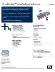
COUNTY mod.8301.05x/07x
REFERENCE MANUAL
software release 2.3x
. . . . . . . . . . LIST OF CONTENTS
1
- 1.1
- 1.2
- 1.3
- 1.4
- 1.5
- 1.6
- 1.7
- 1.8
- 1.9
- 1.10
TECHNICAL FEATURES . . . . . . . . . . . . . . . . . . . . . . . . . . . . . . . . . 3
Keyboard . . . . . . . . . . . . . . . . . . . . . . . . . . . . . . . . . . . . . . . . . . . . . . 3
ON/OFF control . . . . . . . . . . . . . . . . . . . . . . . . . . . . . . . . . . . . . . . . . 3
Counting direction . . . . . . . . . . . . . . . . . . . . . . . . . . . . . . . . . . . . . . . 3
Component lead number . . . . . . . . . . . . . . . . . . . . . . . . . . . . . . . . . 4
Control section . . . . . . . . . . . . . . . . . . . . . . . . . . . . . . . . . . . . . . . . . . 4
Preset data entry keyboard . . . . . . . . . . . . . . . . . . . . . . . . . . . . . . . . 4
Special functions . . . . . . . . . . . . . . . . . . . . . . . . . . . . . . . . . . . . . . . . 4
Back side connections . . . . . . . . . . . . . . . . . . . . . . . . . . . . . . . . . . . . 5
Models . . . . . . . . . . . . . . . . . . . . . . . . . . . . . . . . . . . . . . . . . . . . . . . . 5
Optional accessories. . . . . . . . . . . . . . . . . . . . . . . . . . . . . . . . . . . . . 5
2
- 2.1
- 2.2
- 2.3
SET UP . . . . . . . . . . . . . . . . . . . . . . . . . . . . . . . . . . . . . . . . . . . . . . . 6
Unpacking . . . . . . . . . . . . . . . . . . . . . . . . . . . . . . . . . . . . . . . . . . . . . 5
Locating your County . . . . . . . . . . . . . . . . . . . . . . . . . . . . . . . . . . . . . 5
Power supply . . . . . . . . . . . . . . . . . . . . . . . . . . . . . . . . . . . . . . . . . . . 5
3
- 3.1
- 3.2
- 3.3
- 3.4
- 3.5
OPERATIVE INSTRUCTIONS . . . . . . . . . . . . . . . . . . . . . . . . . . . . . 7
Preliminary operations . . . . . . . . . . . . . . . . . . . . . . . . . . . . . . . . . . . . 7
Totalizer . . . . . . . . . . . . . . . . . . . . . . . . . . . . . . . . . . . . . . . . . . . . . . . 7
PRESET mode counting . . . . . . . . . . . . . . . . . . . . . . . . . . . . . . . . . . 7
Battery . . . . . . . . . . . . . . . . . . . . . . . . . . . . . . . . . . . . . . . . . . . . . . . . 8
Maintenance . . . . . . . . . . . . . . . . . . . . . . . . . . . . . . . . . . . . . . . . . . . 8
4
- 4.1
SMD ADAPTOR . . . . . . . . . . . . . . . . . . . . . . . . . . . . . . . . . . . . . . . . 9
Operative instructions . . . . . . . . . . . . . . . . . . . . . . . . . . . . . . . . . . . . 9
5
EXTERNAL DETECTOR. . . . . . . . . . . . . . . . . . . . . . . . . . . . . . . . . . 9
6
- 6.1
- 6.2
- 6.3
SUPERFORM PREFORMING MACHINE CONTROL . . . . . . . . . . 10
Totalizer . . . . . . . . . . . . . . . . . . . . . . . . . . . . . . . . . . . . . . . . . . . . . . 10
Preset mode. . . . . . . . . . . . . . . . . . . . . . . . . . . . . . . . . . . . . . . . . . . 10
Slow down mode . . . . . . . . . . . . . . . . . . . . . . . . . . . . . . . . . . . . . . . 10
7
- 7.1
- 7.2
- 7.3
THERMAL LABEL PRINTER. . . . . . . . . . . . . . . . . . . . . . . . . . . . . 11
Parameter setup . . . . . . . . . . . . . . . . . . . . . . . . . . . . . . . . . . . . . . . 11
Parameters . . . . . . . . . . . . . . . . . . . . . . . . . . . . . . . . . . . . . . . . . . . 12
Label printing . . . . . . . . . . . . . . . . . . . . . . . . . . . . . . . . . . . . . . . . . . 12
8
RS232C SERIAL OUTPUT . . . . . . . . . . . . . . . . . . . . . . . . . . . . . . . 13
9
- 9.1
- 9.2
CALIBRATION PROCEDURE AND TEST . . . . . . . . . . . . . . . . . . 14
Automatic recalibration . . . . . . . . . . . . . . . . . . . . . . . . . . . . . . . . . . 14
Manual recalibration. . . . . . . . . . . . . . . . . . . . . . . . . . . . . . . . . . . . . 14
CE CONFORMITY. . . . . . . . . . . . . . . . . . . . . . . . . . . . . . . . . . . . . . 15
SECURITY. . . . . . . . . . . . . . . . . . . . . . . . . . . . . . . . . . . . . . . . . . . . 15
WARRANTY . . . . . . . . . . . . . . . . . . . . . . . . . . . . . . . . . . . . . . . . . . 15
REPAIR . . . . . . . . . . . . . . . . . . . . . . . . . . . . . . . . . . . . . . . . . . . . . . 15
Protecting the environment . . . . . . . . . . . . . . . . . . . . . . . . . . . . . . . 15
2
COUNTY 8301.05x/7x - Apr.06
1 . . . . . . . . . TECHNICAL FEATURES
1.1
1.2
KEYBOARD
CLEAR
7
8
9
PRESET
4
5
6
0
1
2
3
: 10
:9
:8
:7
:6
:5
:4
:3
:2
:1
ON
OFF
ON/OFF CONTROL
ON
OFF
Keyboard section :
ON
On :. . . . . . . . . . . . . . . . . . . . . . . . . . . . . .
press the
pushbutton
. . . . . . . . . . . . . . . . . . . . . . . . . . . . . and hold it until the County lights on.
Off : . . . . . . . . . . . . . . . . . . . . . . . . . . . . . . . . . . . . . . . . . . .
1.3
push
OFF
COUNTING DIRECTION
L1
L2
Keyboard section :
. . . . . . . . . . . . . . . . . . . . . . . . . . . . = left counting direction (L1 is on)
. . . . . . . . . . . . . . . . . . . . . . . . . . . = right counting direction (L2 is on)
COUNTY 8301.05x/7x - Apr.06
3
1.4
COMPONENT LEAD NUMBER
L3
: 10
:9
:8
:7
:6
:5
:4
:3
:2
:1
Keyboard section :
L3 led bar graph indicates the actual divider.
1.5
Press
to increase component lead number.
Press
to decrease component lead number.
CONTROL SECTION
Press
CLEAR
CLEAR
to reset display and to set TOTALIZER mode counting.
PRESET
Press
to recall previous memorized preset value and to set
PRESET mode counting.
PRESET
1.6
PRESET DATA ENTRY
0
7
8
9
4
5
6
1
2
3
for preset value data entry
1.7
SPECIAL FUNCTIONS
This key is reserved for special functions
1)During programmation:
Printer parameter setting: Country, date, time, Bar Code
2)During execution: thermal label printing.
4
COUNTY 8301.05x/7x - Apr.06
1.8
BACK SIDE CONNECTIONS
1
1
8301.051
8301.052
8301.072
8301.053
8301.054
8301.074
S.N. 152537
1.9
MODELS
8301.051 . . . . . . . . . . . . . . . . . . . . . . . . . . . . . . . . . . . . . . . . . . . . 220Vac
8301.052 . . . . . . . . . . . . . . . . . . . . . . . . . . . County with battery, 220Vac
8301.072. . . . . . . . . . . . 220Vac, with battery, relay , printer output, watch
8301.053 . . . . . . . . . . . . . . . . . . . . . . . . . . . . . . . . . . . . . . . . . . . . 110Vac
8301.054 . . . . . . . . . . . . . . . . . . . . . . . . . . . County with battery, 110Vac
8301.072. . . . . . . . . . . . 110Vac, with battery, relay , printer output, watch
1.10
OPTIONAL ACCESSORIES
8301.023 (optional) . . . . . . . . . . . . . Complete support for rolled bandolier
8301.025 (optional) . . . . . . . . . . . . . . . . . . . . . . . . . . . . . Bandolier handle
8301.031 (optional) . . . . . . . . . . . . . . . . . . . . . . . . . . EXTERNAL PROBE
. . . . . . . . . . . . . . . . . . . . . . . . . . to be fitted with SUPERFORM machines
8301.033 (optional) . . . . . . . . . . . . . . . . . . . . . . . . . . . . . Connecting cable
. . . . . . . . . . . . . . . . . . . . . . . . . . . . . . . for SUPERFORM machine control
8301.018 (optional) . . . . . . . . . . . . . . . . . . . . . . . . . . . . . . . . SMD adaptor
8301.028 (optional) . . . . . . . . . . . . . . . . . . . . . . . . . . . . . SMD rell support
8301.030 (optional) . . . . . . . . . . . . . . . . . . . . Handle for SMD rell support
8301.090 . . . . . . . . . . . . . . . . . . . . . . . . . . . . . . . . . Thermal Label Printer
8301.091 . . . . . . . . . . . . . . . . . . . . Thermo-adhesive roll paper, 20meters
COUNTY 8301.05x/7x - Apr.06
5
2 . . . . . . . . . . . . . . SET UP
2.1
UNPACKING
Open the carton and check to see all the following items are there :
1) COUNTY component counter corresponding to the model printed on
the outside of the packing carton.
2) Power cord.
3) User's manual.(this manual)
WARNING:
As you unpack the County, set aside and save the packing materials.They
will come in handy in case you need to transport it or send it back to recalibration.
2.2
LOCATING THE COUNTER
Choose the location for the County, using the following guidelines:
Choose a flat surface , with enough space for component handling
Avoid direct sunlight (display will be more readable)
Use the counter within the following ranges :
Ambient temperature:
0°C to 40°C
Relative humidity:
10% to 80% (non-condensation)
2.3
POWER SUPPLY
Attach first the power cord to the counter and then into an appropriate AC
outlet.
WARNING:
The counters with rechargeable battery should be connectede to an AC outlet continuosly powered, in order to allow a complete recharge of the battery.
( the medium recharge time is about 12 hours)
6
COUNTY 8301.05x/7x - Apr.06
3 . . . . . . . . OPERATIVE INSTRUCTIONS
3.1
PRELIMINARY OPERATIONS
Lighting: press the
ON
pushbutton and hold it until the County lights on.
Counting direction : select the counting direction by pressing
or
.
Counting direction is indicated by the LED placed upon the keybutton
(L1 or L2).
Select the number of component leads by pressing :
or
(L3 led bar graph indicates the actual divider):
1 . . . . . . . . . . . . . . . . . . . . . . . . . . . . . . . . . . . . . . . . 1 for resistances, etc.
2 . . . . . . . . . . . . . . . . . . . . . . . . . . . . . . . . . . . . 2 for radial capacitors, etc.
3 . . . . . . . . . . . . . . . . . . . . . . . . . . . . . . . . . . . . . . . . . 3 for transistors, etc.
SMD components
up to 19 for SMD
SMDcomponents
3 comp/ 2 holes
components
2 comp/ 1 hole
19
: 10
:9
:8
:7
:6
:5
:4
:3
:2
:1
: 10
:9
:8
:7
:6
:5
:4
:3
:2
:1
: 10
:9
:8
:7
:6
:5
:4
:3
:2
:1
AXIAL COMPONENT COUNTING
RADIAL COMPONENT COUNTING
1 - Pull up the tape guide
COUNTY 8301.05x/7x - Apr.06
2 - Rotate the guide of 180°
7
3.2
TOTALIZER
CLEAR
Press
to reset the display.
Pull through the component bandolier according to the feed direction.
After 10.000 counts and up to 899999 the two most significative digits will appear alternatively to the four least significative ones that are normally visible
on the display.
3.3
PRESET MODE
PRESET
Press
to reset the display.
Digit the desidered component number.
Pull through the bandolier; the County will count down; the “undF”(underflow) message will appear if zero has been surpassed; an intermittent buzzing tone will signal, with different repetition frequency, the relative position
with respect to zero.
PRESET
To recall the previously set number press
.
Preset mode counting is indicated by the divider LED blinking.
Press
CLEAR
before setting a new number.
After 4 inoperative minutes the counter will be switched off automatically.
3.4
BATTERY
For recharging, keep the mains cable inserted with the counter in the OFF
state.
For battery maintenance, please recharge at least once a month. Do not
store the counter with the battery full down.
3.5
MAINTENANCE
Keep the lenses of the optical head clean with a cloth moistened with a cleaning product.
8
COUNTY 8301.05x/7x - Apr.06
4 . . . . . . . . . . . SMD ADAPTOR
The County adaptor for taped SMD components counting is an option. Components counting is achieved by counting the punched holes on the SMD
tape.
4.1
OPERATIVE INSTRUCTION
1)Insert the adaptor on the guide rods , apply a slight pressure until the adaptor is locked in place.
2)Push the adaptor in contact with the optical head.
3)Cut the tape to the middle of the first hole.
4)Select the correct number of holes per component by pressing :
or
(L3 led bar graph indicates the actual divider)
5)Push trought the tape until the the hole of the first component to be counted
is in correspondence with the center of the wheel then continue in the usual
way(totalizer or preset mode).
NOTE: take care at the counting end not to take off the tape of the wheel
because any free wheel motion will cause an excess of counts.
5 . . . . . . . . . . . EXTERNAL HEAD
An input for an external counting head is disposable on the DB9(JP15) connector.
In order to count with this external detector is sufficient to insert the head into
JP15, the internal counting head will be disabled and counting functions will
be performed from the external one.
COUNTY 8301.05x/7x - Apr.06
9
6. . . . . . SUPERFORM MACHINES CONTROL
(only for 8301.052/054/072/074)
6.1
TOTALIZER
TOTALIZER counting mode :
1) Insert the connecting cable between COUNTY and the SUPERFORM,
and fit the external counting head to the left input guide of the SUPERFORM
machine.
CLEAR
2)Push
3) Pull trought the bandolier into the preforming machine, the COUNTY will
totalize the component number.
6.2
PRESET MODE
PRESET counting mode :
1) Insert the connecting cable between COUNTY and the SUPERFORM,
and fit the external counting head to the left input guide of the SUPERFORM
machine.
2) Digit on the keyboard the desired component number or recall the prePRESET
vious presetted number by pushing the
key.
3) Start the SUPERFORM motor by acting on the ON/OFF pushbutton.
4) Set the most suitable SUPERFORM speed.
5) COUNTY will automatically stop the SUPERFORM when the presetted
component number will be reached.
NOTE: the component number at SUPERFORM stop could differ of some
units from the actual presetted number; this is due to the absence of a low
speed motor drive control by the COUNTY.
If the presetted value is to be reached exactly then you have to operate in
“SLOW-DOWN” mode.
6.3
SLOW-DOWN MODE
1) In order to operate in PRESET mode with slow down motor control keep
pressed the
PRESET
key for about 3 seconds, until the display of the COUNTY
will show the message “SET LOW”, at this point push again the
PRESET
or the
CLEAR
key, now you are in “SLOW-DOWN” mode.
2) Digit on the keyboard the desired component number or recall the prePRESET
vious presetted number by pushing the
key.
3) Start the SUPERFORM motor by acting on the ON/OFF pushbutton.
4) Set the most suitable SUPERFORM speed.
5) COUNTY will automatically stop the SUPERFORM some components
before the presetted number and the display will show the message “SET
LOW”.
6) Set the SUPERFORM motor drive speed at the minimum and restart the
motion by acting on the ON/OFF pushbutton.
7) “SET LOW” message will get out and the COUNTY will stop the SUPERFORM exactly on the 0, that is the desired component number.
10
COUNTY 8301.05x/7x - Apr.06
7 . . . . . . . . THERMAL LABEL PRINTER
Only for 8301.072 and 8301.074 models.
Sample of a printed label , Bar Code included.
NOTE: fit togheter the printer and the counter with the data cable included
and with the power supply off.
7.1
PARAMETER SETUP
With the counter in the “OFF” state keep the
on the counter with the
ON
button pressed while light
button.
Select the parameter to be modified by pressing
or
PRESET
To recall the previously set number press
If you are editing a numerical type parameter (date, time, year, month) digit
PRESET
the new data and press
.
If you are editing a special type parameter (country, Bar Code) press keys
from 0 on , until you will reach the desired value.
Press
PRESET
in order to store the new value.
COUNTY 8301.05x/7x - Apr.06
11
7.2
SETTABLE PARAMETERS
COUNtry
Language of the words in the label:
0=USA, 1=ENG, 2=ITA, 3=FRA, 4=GER, 5=SPA
YEAR
MONTh
DAY
HOURs
MINUtes
year
month
day of the month
hour
minutes
BAR_CODE
Bar Code setting
0 = OFF (Bar Code is not printed)
2 = CODE 39 T, where “T” means that only the total
number of pieces will be printed
3 = CODE 39 DT, where “DT” means that the BarCode
will be printed on 2 lines, one for the date and one
for the total quantity.
4 = ITF (interleaved 2 of 5)
6 = CODE 128 A (code 128 character subset A))
PRINt_LABEL 0 = ON, the alphanumeric section of the label will be
printed
1 = OFF, only BarCode will be printed.
BAUD RATE
7.3
LABEL PRINTING
Press
12
RS232C settings.
0 = OFF, output is setted for the label printer
1 = 1200 bauds, 2=2400 , 3=4800 , 4=9600
key.
COUNTY 8301.05x/7x - Apr.06
8. . . . . . . . . RS232C SERIAL OUTPUT
CONNECTION DIAGRAM AND TRANSMISSION PROTOCOL
County Output
connector
2
5
4
9
PC input
connector
TRANSMISSION PROTOCOL :
When the
key is pressed the COUNTY transmits an ASCII bytes sequence with the following significance :
1
2)
3)
4)
5)
6)
7)
8)
START
01H
digit 6 (most significative digit)
digit 5
digit 4
digit 3
digit 2
digit 1 (units , less significative digit)
STOP
04H
( SOH )
( EOT )
PARAMETERS SETTING
BAUD RATE
RS232C settings.
0 = OFF, output is setted for the label printer
1 = 1200 bauds, 2=2400 , 3=4800 , 4=9600
COUNTY 8301.05x/7x - Apr.06
13
8. . . . . CALIBRATION PROCEDURE AND TEST
8.1
AUTOMATIC RECALIBRATION
The 8301.05x models are provided with an intelligent self calibration routine
that is performed automatically at power on.
If optical parameters go out of tolerance limits then is necessary a manual recalibration and test.
If this happens the display will show the message : “Err_Cal” (calibration error)
8.2
MANUAL RECALIBRATION
Connect mains power cord. With the counter in the “OFF” state keep the
PRESET
button pressed while light on the counter with the
ON
button.
ATTENTION : be sure that no components or SMD adaptor are in the optical head.
Display will show alternatively the channel 1 and the channel 2 calibration
values.
Check the two values and make this controls:
1)Values have to be >12
2)Difference between them should be
<0.25*channel 1 value and <0.25*channel 2 value
for example : channel 1=25
channel 2=24
difference=1
max.allowable difference=24*0.25=6
If step 1 or step 2 are not satisfied then the optical head should be mechanically recalibrated.(consult your own dealer for furter details)
OFF
To exit from the calibration procedure keep pressed the
Then light again the counter and operate in the usual way.
14
button.
COUNTY 8301.05x/7x - Apr.06
EC CONFORMITY
Units 8301.051, 8301.052, 8301.053 and 8301.054 conform to EC directives
2004/108/EC and 2006/95/EC , the following harmonized standards are in use
EN 60204-1, EN 61000-6-1, EN 61000-6-3.
A weighted sound pressure <70dB (A)
A weighted sound power < 85dB (A)
SAFETY INSTRUCTIONS
Attach first the power cord to the counter and then into an appropriate AC
outlet.
The counter shall be connected to an electrical system having ground connection..
WARRANTY
This unit is guaranteed against all defects due to faulty materials and workmanship, within 12 months from the date of purchase.
A use not conforming to what specified might be dangerous to the safety of
the operator and may damage the unit.
In such circumstances the manufacturer is relieved of any liability and the
warranty itself will decay.
REPAIR
Repairs have not been attempted by anyone other than authorized repair
distributors.
Do not try to repair the unit by yourself.
ATTENTION: Dangerous voltage is present inside the unit.
Protecting the environment
Separate collection.This product must not be disposed of with normal household waste.
Should you find one day that your product needs replacement,or if it is of no
further use to you,do not dispose of it with household waste. Make this product available for separate collection.
Separate collection of used products and packaging allows materials to be
recycled and used again.
Re-use of recycled materials helps prevent environmental pollution
and reduces the demand for raw materials.
Local regulations may provide for separate collection of electrical
products from the household,at municipal waste sites or by the
retailer when you purchase a new product.
COUNTY 8301.05x/7x - Mag.2010
15