1
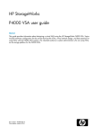
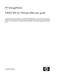
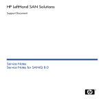
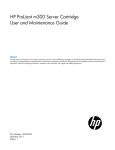
HP
P4000 Multi-Site HA/DR Solution Pack User
Guide
Abstract
This guide contains detailed instructions for designing and implementing the Multi-Site SAN features of the HP P4000 SAN
Solution. The Multi-Site SAN features enable you to synchronously and automatically mirror data between geographic sites.
Topics include designs for network configurations and instructions about implementing the network designs. The intended
audience is system administrators who manage HP P4000 SAN solutions.
For the latest version of this guide, see the HP website http://www.hp.com/support/manuals.
HP Part Number: AX696-96074
Published: September 2011
Edition: 5
© Copyright 2009, 2011 Hewlett-Packard Development Company, L.P.
Confidential computer software. Valid license from HP required for possession, use or copying. Consistent with FAR 12.211 and 12.212, Commercial
Computer Software, Computer Software Documentation, and Technical Data for Commercial Items are licensed to the U.S. Government under
vendor's standard commercial license.
The information contained herein is subject to change without notice. The only warranties for HP products and services are set forth in the express
warranty statements accompanying such products and services. Nothing herein should be construed as constituting an additional warranty. HP shall
not be liable for technical or editorial errors or omissions contained herein.
Acknowledgements
Microsoft, Windows, Windows XP, and Windows NT are U.S. registered trademarks of Microsoft Corporation.
Contents
1 Designing a Multi-Site SAN.........................................................................4
Failover Manager overview........................................................................................................4
Requirements...........................................................................................................................4
Designing a Multi-Site SAN........................................................................................................4
Configuring data replication for optimal availability and redundancy.........................................5
Configuring sites and quorum managers to achieve optimal high availability and redundancy.......6
Alternative setups.................................................................................................................9
Designing the network for the Multi-Site SAN.............................................................................10
Best practices for implementing the Multi-Site SAN network.....................................................10
Common Multi-Site SAN network designs..............................................................................11
Sample recommended network configurations for Multi-Site SANs............................................11
Using multiple subnets .......................................................................................................14
Setting up application clusters in a Multi-Site SAN environment.....................................................17
Using the Primary Site designation in two-site configurations....................................................18
Recover quorum operation..................................................................................................18
Best practices for configuring quorum and managers in a Multi-Site SAN environment................18
2 Implementing a Multi-Site SAN...................................................................20
Before you begin....................................................................................................................20
Preparing to install a new Multi-Site SAN..............................................................................20
Preparing to convert an existing SAN to a Multi-Site SAN.......................................................20
Installing the Multi-Site SAN.....................................................................................................20
Creating the management group.........................................................................................21
Creating Multi-Site clusters and volumes................................................................................21
Converting an existing SAN to a Multi-Site SAN.........................................................................23
Prerequisites......................................................................................................................23
Configuring managers............................................................................................................24
Overview..........................................................................................................................24
Configuring regular managers.............................................................................................24
Installing and configuring a Failover Manager.......................................................................24
Configuring sites....................................................................................................................25
Viewing sites in the CMC....................................................................................................26
Designating a primary site..................................................................................................27
Adding a site....................................................................................................................27
Editing a site.....................................................................................................................27
Deleting a site...................................................................................................................27
Adding storage systems to a Multi-Site cluster.............................................................................28
Adding additional capacity to existing sites...........................................................................28
Removing storage systems from a Multi-Site cluster.......................................................................29
To remove the storage systems from the site...........................................................................29
Removing servers from a site....................................................................................................29
3 Support and other resources......................................................................30
Contacting HP........................................................................................................................30
Subscription service............................................................................................................30
HP Insight Remote Support Software..........................................................................................30
New and changed information in this edition.............................................................................31
Related information.................................................................................................................31
HP websites......................................................................................................................31
Glossary....................................................................................................32
Index.........................................................................................................38
Contents
3
1 Designing a Multi-Site SAN
The Multi-Site SAN features enable you to synchronously mirror data between sites automatically.
You create a Multi-Site SAN by configuring equal numbers of storage systems into sites in the
software. The Multi-Site SAN software enables a variety of features that are based on geographic
awareness and synchronous replication:
•
Multi-Site clusters that can:
◦
Span up to three sites
◦
Span multiple subnets
◦
Have multiple VIPs
•
Geographical awareness, enabled by designating storage systems as members of a particular
site.
•
Synchronously replicated (mirrored) data between sites, based on volume data protection
level.
•
Site information that ensures that data is mirrored between sites for high availability and
disaster recovery.
•
I/O path preferencing, so that application servers connect to storage systems located in the
same site.
•
Failover Manager support for automatic failover/failback in three-site configurations without
requiring a physical storage system in the third site.
•
Failover Manager for quorum management if the network connection between the two sites
becomes unavailable.
•
Recover quorum via CLI when a site failure also results in losing quorum in the management
group.
Failover Manager overview
The Failover Manager is a specialized version of the SAN/iQ software, designed to run as a
virtual appliance in a VMware environment. The Failover Manager participates in the management
group as a real manager in the system; however, it performs quorum operations only, not data
movement operations. It is especially useful in a Multi-Site SAN configuration to manage quorum
for the multi-site configuration without requiring additional physical hardware at a site.
The Failover Manager is supported on VMware Server, Workstation, and Player. For detailed
information about installing and configuring the Failover Manager, see “Using Specialized
Managers” in the HP P4000 SAN Solution User Guide.
Requirements
•
A Multi-Site SAN requires a feature key for each storage system in the management group
that is also participating in a Multi-Site cluster.
•
All sites must have the same number of storage systems. Storage systems must be added to
or removed from Multi-Site clusters equally.
Designing a Multi-Site SAN
The Multi-Site SAN software offers multiple features and the design flexibility to protect against
certain types of failures in the environment.
Data replication, site design, and quorum managers combine to protect against certain types of
failures in the environment. Some of the common types of failures a Multi-Site SAN protects against
include data center failures and storage system failures:
4
Designing a Multi-Site SAN
Data center failures
•
Site power outage
•
Site network outage
•
Site disaster (fire, flood, terrorist attack, and so forth)
Individual storage system failures
•
Power outage
•
Network outage
•
System disaster
•
System failure (backplane, motherboard, RAM, CPU)
Configuring data replication for optimal availability and redundancy
The SAN/iQ software offers six levels of synchronous replication at a volume level. In order to
protect the data across sites, you must choose a data protection level with a number of mirrors that
is at least equal to the number of sites in the configuration. For instance, if the storage cluster spans
three sites, then volumes must be configured as Network RAID–10+1 in order to insure that data
is the same on each site.
NOTE:
Network RAID-0, Network RAID-5, and Network RAID-6 will not tolerate site failures.
“Data protection levels and the supported number of sites” (page 5) describes the data replication
levels for the Multi-Site SAN and associated supported configurations.
Table 1 Data protection levels and the supported number of sites
Data protection level
Number of sites supported
Network RAID-10
2
Network RAID–10+1
3
NOTE: 2 sites are supported, but not considered a best
practice configuration
Network RAID–10+2
2
NOTE: 3 sites are supported, but are not considered a
best practice configuration
When to use Network RAID-10+2
Using Network RAID-10+2 offers a level of data protection that enables the Multi-Site SAN to
sustain a complete failure at one site and still maintain replicated data at the other site. For instance,
with Network RAID-10+2 there are four copies of data for the volume on the SAN. In a two-site
configuration, the Multi-Site SAN software puts two of the four copies in one site and the remaining
two in the other. If a site fails, the remaining site still has two copies and remains fault-tolerant.
Designing a Multi-Site SAN
5
Figure 1 Sample configuration for two-site, data protection level Network RAID-10+2
1. Volumes are configured with Network RAID-10+2
Configuring sites and quorum managers to achieve optimal high availability and
redundancy
Several recommended site configurations can be used with the Multi-Site SAN software. These
configurations provide varying levels of availability and redundancy. “Common configurations of
Multi-Site SANs and mangers” (page 7) shows the recommended configurations. Select the one
that best matches your environment.
6
Designing a Multi-Site SAN
In addition to setting up the Multi-Site clusters for data replication, it is important to set up the SAN
managers for quorum correctly to ensure that in the event of a failure the system can be properly
recovered. Maintaining quorum can be either an automated process or manually recovered by an
Administrator. Table 2 (page 7) summarizes common Multi-Site SAN and manager configurations.
Table 2 Common configurations of Multi-Site SANs and mangers
Number of sites
Cluster/site setup
Total number of
Failover Manager
managers of all types
Site types
three physical sites
Cluster spans two sites Min = three; Max =
five
In the third site
two physical sites,
with logical third site
Cluster spans two sites Min = three; Max =
five
In the logical third site All sites are peer.
three physical sites
Cluster spans three
sites
Min = three; Max =
six
Not used
All sites are peer.
two physical sites
Cluster spans two sites Min = three; Max =
five
Not used
One site is designated
primary.
All sites are peer.
Best practice
In a cluster that spans multiple sites, run the same number of managers in each site. In a cluster
that spans two sites, run a Failover Manager in a third site (physical or logical) that is not included
in the cluster (“Three physical sites: cluster spans two sites, Failover Manager in third site”
(page 8)). The one exception to this rule is the two-site configuration in which one site is configured
as primary (“Two physical sites: cluster spans two sites, one site is the primary site” (page 9)). In
this case, run a majority of the managers in the primary site.
Sample configurations
The following diagrams illustrate best practice for four different configurations:
•
“Three physical sites: cluster spans two sites, Failover Manager in third site” (page 8)
•
“Two physical sites, logical third site: cluster spans two sites, Failover Manager in logical third
site” (page 8)
•
“Three physical sites: cluster spans three sites” (page 9)
•
“Two physical sites: cluster spans two sites, one site is the primary site” (page 9)
Designing a Multi-Site SAN
7
Figure 2 Three physical sites: cluster spans two sites, Failover Manager in third site
1. Volumes are configured with Network RAID-10
Figure 3 Two physical sites, logical third site: cluster spans two sites, Failover Manager in logical
third site
1. Volumes are configured with Network RAID-10
8
Designing a Multi-Site SAN
Figure 4 Three physical sites: cluster spans three sites
1. Volumes are configured with Network RAID-10+1
Figure 5 Two physical sites: cluster spans two sites, one site is the primary site
1. Volumes are configured with Network RAID-10
Alternative setups
The Multi-Site SAN software supports many other valid configurations than the four illustrated in
the prior section.“Alternative Multi-Site SAN configurations ” (page 10) lists other possible
configurations.
Designing a Multi-Site SAN
9
Table 3 Alternative Multi-Site SAN configurations
Alternate configuration
Description
Details
More than one Multi-Site cluster in
the management group
Multiple clusters running within the The Multi-Site SAN software supports running
same management group.
many clusters in the same management
group. You simply need to make sure that
clusters have the same number of storage
systems in each site for that particular cluster.
More than three sites
There are more than three sites in
the cluster.
A particular cluster can only span up to three
sites. However, the Multi-Site SAN software
supports having more than one cluster. The
different clusters can span different sites
within the same cluster.
Using Virtual Manager
The Virtual Manager capability
remains in the product (a manual
process for recovering quorum).
The Virtual Manager is used in two-site
configurations, and is not as commonly used
as the Failover Manager. For more
information about the Virtual Manager, see
the chapter “Special Managers” in the HP
P4000 SAN Solution User Guide.
Using Remote Copy with Multi-Site
SAN
The cluster contains Remote Copy,
which like all other SAN/iQ
features, is compatible with
Multi-Site SAN.
You can use Remote Copy to replicate data
from a Multi-Site SAN to a Disaster Recovery
or Backup site. See the chapter
“Understanding and Planning Remote Copy”
in the Remote Copy User Manual.
Multiple subnet clusters in the same
site
The Multi-Site SAN features can be The Multi-Site SAN software can be used to
used to set up clusters that span
create clusters that span multiple networks
multiple subnets in the same site. (subnets) in larger Enterprise data centers.
The storage systems all reside in the same
site. However, the cluster must be Multi-Site
if it is to contain storage systems from
different subnets.
Designing the network for the Multi-Site SAN
Good network design is a critical part of setting up a Multi-Site SAN that meets your needs. A
good Multi-Site SAN network encompasses the following attributes:
•
Reliability
•
High availability
•
High performance
This section contains information about the minimum recommended network design considerations
when planning a network to support a Multi-Site SAN.
Best practices for implementing the Multi-Site SAN network
10
•
Adequate bandwidth—Plan for 50 MB/sec of bandwidth for each storage system in each
site. For instance, if each site contains five storage systems, then you need 250 MB/sec
throughput. In this case, that translates into two Gigabit Ethernet links, or more.
•
Low round-trip latency—In order to not impact disk I/O to the application server, the round-trip
latency between the sites must be no more than 2 ms.
•
Redundant links—Have multiple physical connections (media) between the sites for redundancy.
The network should be configured so that a link failure does not cause the Multi-Site SAN to
go offline.
Designing a Multi-Site SAN
•
•
Assign servers to sites—Avoid high-latency connections by assigning application servers to
the site where the server is located. Application servers assigned to a site connect only to
storage systems in the same site as follows:
◦
Without MPIO—With servers set up in the CMC with the load balancing option, the
system sets up the iSCSI session only to storage systems assigned to the same site.
◦
With MPIO and the HP DSM—The system sets up iSCSI sessions only to storage systems
assigned to the same site.
◦
With MPIO and the Microsoft DSM—With servers set up in the CMC with the load
balancing option, the system sets up the iSCSI session only to storage systems assigned
to the same site.
Use the Failover Manager—Unless you have storage systems in three physical sites, use a
Failover Manager. Put the Failover Manager in the third site (physical or logical) located on
a network that is isolated from the other sites and has a different power connection.
Common Multi-Site SAN network designs
Based on the Multi-Site SAN configuration, there are many network designs that can be implemented
that solve the redundancy, high availability, and performance requirements for the Multi-Site SAN.
A few commonly used designs are:
•
Dual redundant links between the sites
•
Full-mesh triangular (three) redundant links between sites
•
Hub and spoke central network core with redundant links out to each site
•
Combination full-mesh core network with triangular (three) links between sites
Balancing the requirements for high availability during certain types of failures in the Multi-Site
SAN and the budget associated with the network infrastructure typically dictates the network
architecture a customer will choose to implement. Obviously, the most redundant network typically
will cost the most to implement. However, not implementing redundancy in the Multi-Site SAN
network significantly curtails the benefits of the Multi-Site SAN software. “Common Multi-Site
network configurations and failure protection of each” (page 11) shows the common Multi-Site
network configurations and the types of failures against which they provide protection.
Table 4 Common Multi-Site network configurations and failure protection of each
Network topology
Site failure protection
Network failure protection
Storage system failure
protection
Dual redundant links
between sites
Yes, with manual
intervention
Yes
Yes
Full-mesh triangular links
between sites
Yes
Yes
Yes
Hub & spoke central core
Yes
Yes, so long as the core
does not fail
Yes
Yes
Yes
Combo full-mesh core with Yes
triangular links between sites
Sample recommended network configurations for Multi-Site SANs
Samples of common network configurations for the topologies described in “Common Multi-Site
network configurations and failure protection of each” (page 11) are illustrated in this section. The
clusters and sites can have many more storage systems than are depicted here. However, the
pictures are more focused on the network design.
Designing the network for the Multi-Site SAN
11
Figure 6 Dual redundant links between two sites
1. Dual redundant GigE links
Figure 7 Dual redundant links between two sites with Failover Manager in logical third site
1. Dual redundant GigE links
2. Optional redundant path
12
Designing a Multi-Site SAN
Figure 8 Triangular network with Failover Manager
1. Dual redundant GigE links
Figure 9 Hub and spoke network core with redundant links out to each site
1. Core network hub and spoke
Designing the network for the Multi-Site SAN
13
Figure 10 Combination full-mesh core with triangular links to all sites
1. Full mesh core network
Using multiple subnets
You can use multiple subnets with a Multi-Site SAN. Multiple subnets let you have multiple VIPs,
one VIP per subnet. The advantage of using multiple VIPs is that you can connect to a volume
without having to leave the local subnet.
Alternatively, you can assign an application server to a site. Application servers assigned to a site
connect only to storage systems in the same site. For more information, see “Best practices for
implementing the Multi-Site SAN network” (page 10).
If you use multiple subnets within the iSCSI cluster and implement one subnet per site, you can take
advantage of the following Multi-Site SAN features:
•
One Virtual IP address per site. iSCSI discovery sessions are terminated on a storage system
that is local to the application server in that site.
•
Virtual IP addresses are hosted only on storage systems that reside in the same subnet as the
VIP.
•
Read and Write I/O requests are forwarded from the application server to a storage system
that is in the same site as the server. This ensures that the I/O path is optimal and multiple
network hops across the network link between the sites are eliminated.
“Multi-Site SAN mapping to subnets, VIPs, and application servers” (page 15) shows an example
of how the Multi-Site SAN setup maps to subnets, VIPs, and application servers.
14
Designing a Multi-Site SAN
Figure 11 Multi-Site SAN mapping to subnets, VIPs, and application servers
1. Dual redundant GigE links
Connecting volumes to multiple subnets in a Multi-Site SAN using the Microsoft iSCSI initiator
Connecting to volumes in a multiple subnet configuration is similar to connecting to volumes in a
single-site configuration, with the following important differences:
•
You must configure all cluster VIPs for discovery, for proper failover/failback configuration of
a Multi-Site SAN. List the VIPs in the preferred order of connection. For example, if Site A is
the first preference for connection, put the VIP associated to Site A first in the discovery list.
•
You must also log on to the volumes with the default Target Portal setting.
Using multiple cluster VIPs when connecting to a Multi-Site SAN
Use the Virtual IP address of the HP P4000 SAN Solution cluster when connecting to volumes. In
a multiple subnet configuration, you must enter both of the VIPs of the multi-site cluster on all the
application servers. In addition, all the application servers must have the VIPs listed in the same
order. A sample Multi-Site SAN configuration is shown in Figure 12 (page 16). In this configuration,
the cluster has three sites: Site A, Site B, and Site C. Site A is primary.
Connecting application servers with single or multiple NICs to a Multi-Site SAN
1.
On each application server, enter the cluster VIPs in the same order as on the Discovery tab
of the iSCSI Initiator Properties window.
Designing the network for the Multi-Site SAN
15
Figure 12 Entering VIPs in a Multi-Site SAN configuration
2.
3.
4.
On the Targets tab, select the volume to log on to.
Click Log On.
Select the Enable multi-path check box if using MPIO.
Figure 13 Logging on to volume
5.
6.
7.
16
[Optional] If you want this volume to be available after rebooting, select the Automatically
restore... check box.
Click Advanced to open the Advanced Settings window.
Configure the Advanced Settings as follows:
•
For Local adaptor, select Microsoft iSCSI initiator.
•
For Source IP, select the IP address of the storage NIC to connect to the volume.
•
For Target portal, leave as Default so that the Discovery list of VIPs is used in the same
order on all storage systems.
Designing a Multi-Site SAN
Figure 14 Target portal value remains Default
8. After setting the values, click OK to close the Advanced Settings dialog.
9. Click OK again to finish logging on.
10. If you want to set the MPIO load balancing policy, see the HP P4000 DSM for MPIO
Deployment Guide.
11. If you have multiple NICs, repeat steps 1 through 10 for the additional NICs.
Using MPIO with multiple subnets
When you are using multiple subnets in a Multi-Site SAN, the HP P4000 DSM for MPIO or Microsoft
DSM will only build I/O paths to the storage systems that are in the same subnet as the application
server. See the DSM for MPIO Deployment Guide for more information about MPIO.
When using VMware ESX 4 or higher and its native MPIO in a Multi-Site SAN, you cannot configure
more than one subnet and VIP. Multiple paths cannot be routed across subnets by the ESX/ESXi
4 initiator. With VMware ESX, the preferred configuration is a single subnet and with ESX servers
assigned to sites in SAN/iQ.
Setting up application clusters in a Multi-Site SAN environment
Just as you can set up a Multi-Site SAN for data availability even when a complete site is offline,
you can set up application clusters (Microsoft Cluster Server, VMware ESX Cluster, Linux Cluster,
and so forth) so that the cluster nodes are split between the sites. By having the automated
failover/failback capabilities in the SAN, many application cluster technologies can leverage this
capability to do “stretch” application clustering. Consult the application server specific information
for information about setting up clustering to support this type of failover. In general, you must
perform three tasks:
1. Set up an application server node in each site.
2. Configure the application server to connect to the volumes on the SAN.
3. If using multiple subnets in the storage cluster, log on to both VIPs in the cluster.
If you are using the HP P4000 DSM for MPIO, see the DSM for MPIO Deployment Guide.
Setting up application clusters in a Multi-Site SAN environment
17
Using the Primary Site designation in two-site configurations
The Multi-Site SAN software supports designating a particular site as Primary so that it does not
go offline when the secondary site goes offline, or when the network link between sites goes offline.
This is specific to the two-site configuration where, without this designation, there would be no way
for the system to determine which site should remain online in the event of a network separation
(classically known in the clustering/distributed systems world as a “split-brain” system).
To set up this type of configuration:
1. Designate one of the sites as primary.
2. Start a majority of managers in the primary site.
Contact Customer Support for more information.
Failure modes and recovery steps
In general, there are three failure modes that a configuration like this can encounter that you should
be aware of. “Failure conditions and resolutions” (page 18) summarizes the failure conditions and
what you should do to rectify the issue.
Table 5 Failure conditions and resolutions
Failure condition
Resolution steps
Secondary site offline
None. The primary site will continue to operate.
Network link between sites fails
None. The primary site will continue to operate.
Primary site offline
1. If any of the storage systems running managers in the primary site
can be brought back online, you should do this first.
2. If all storage systems in the primary site are lost forever, you can use
the Recover Quorum command-line function to recover quorum in the
secondary site manually. For more information, see “Recover quorum
operation,” next in this section
Recover quorum operation
The Recover Quorum function is introduced with the Multi-Site SAN as a way to bring volumes
back online in the event that quorum in the management group is lost.
CAUTION: The Recover Quorum function should only be used as a last resort. The failed site
must be completely failed to use Recover Quorum safely on the remaining site.
The
1.
2.
3.
Recover Quorum command-line function performs the following actions:
Removes all offline managers from the management group.
Ejects all offline storage systems from the management group.
The SAN/iQ software is modified to prevent any data integrity issues in the event any of the
offline storage systems are brought back online.
Best practices for configuring quorum and managers in a Multi-Site SAN environment
Configuring the appropriate number of managers in a Multi-Site SAN on the appropriate storage
systems is an important part of setting up the Multi-Site SAN for high availability and fault tolerance.
“Common Multi-Site SAN configurations with recommended managers” (page 19) identifies
common Multi-Site SAN configurations and the recommended manager configurations.
18
Designing a Multi-Site SAN
Table 6 Common Multi-Site SAN configurations with recommended managers
Multi-Site SAN configuration
Manager configuration
Two physical sites, one site is primary For four storage systems, run:
• two managers in the primary site
• one manager in the secondary site
For six storage systems or more, run:
Number of managers and number
Needed to maintain quorum
• Manager count = three
Number for quorum = two
• Manager count = five
Number for quorum = three
• three managers in the primary site
• two managers in the secondary site
Two physical sites, logical third site
For two storage systems, run:
• Manager count = three
• one manager in each site
Number for quorum = two
• one failover manager in the logical
• Manager count = five
third site
Number for quorum = three
• two managers in each site, one
failover manager in the logical third
site
For four storage systems or more, run:
• two managers in each site
• one failover manager in the logical
third site
Three physical sites, cluster spans two For two storage systems, run:
sites
• one manager in each site
• one failover manager in the third site
For four storage systems, run:
• Manager count = three
Number for quorum = two
• Manager count = five
Number for quorum = three
• two managers in each site
• one failover manager in the third site
Three physical sites
For three storage systems, run:
• one manager in each site
For six or more storage systems, run:
• two managers in each site
• Manager count = three
Number for quorum = two
• Manager count = six
Number for quorum = four
Setting up application clusters in a Multi-Site SAN environment
19
2 Implementing a Multi-Site SAN
After you have designed the Multi-Site SAN configuration, you are ready to implement it.
Before you begin
Install Multi-Site SAN feature keys on the storage systems you are going to use.
Register your storage systems. For more information, see “Registering Advanced Features” in the
HP P4000 SAN Solution User Guide for information about registering your storage systems.
Have the following information ready:
•
The layout for storage systems and sites
•
IP addresses, subnets, and VIPs to use for the Multi-Site cluster. You can use one VIP per subnet.
•
(Optional) IP address and subnet for the Failover Manager
Preparing to install a new Multi-Site SAN
After you have finished planning the Multi-Site SAN and installed feature keys on the storage
systems for the SAN, you are ready to begin installation.
Preparing to convert an existing SAN to a Multi-Site SAN
Converting an existing SAN to a Multi-Site SAN includes planning the site layout and network
information along with the following considerations:
•
Do you need to move/remove data from the existing SAN before reconfiguring it?
•
Do you need to purchase additional storage systems to meet the requirement that each site
have the same number of storage systems?
•
Do you need to reconfigure your network to take advantage of the Multi-Site SAN capabilities?
See “Designing the network for the Multi-Site SAN” (page 10) for detailed information about
setting up your network appropriately.
Installing the Multi-Site SAN
To install a Multi-Site SAN, use the Management Groups, Clusters, and Volumes Wizard.
20
Implementing a Multi-Site SAN
Figure 15 Using the management group wizard to create a Multi-Site SAN
NOTE: You must have at least one storage system for each site in the Available Systems pool
before starting.
Creating the management group
The first part of the wizard creates the management group, which includes configuring the optimal
number of managers for the initial setup. After you have the Multi-Site clusters configured, you
need to review the manager configuration and adjust it according to the Multi-Site configuration
you have planned. See “Configuring managers” (page 24).
Creating Multi-Site clusters and volumes
The path through the Multi-Site cluster portion of the wizard follows the steps listed below. The
steps are described in greater detail in“Using the Multi-Site cluster wizard” (page 21).
1. Create a cluster.
2. Create a site and then assign storage systems to the site.
3. Create the additional sites with storage systems, up to a total of three sites.
4. Add one or more VIPs, depending on the number of subnets you have configured.
5. Create volumes using the data protection levels dictated by your Multi-Site cluster design.
Using the Multi-Site cluster wizard
After creating the management group, the Create a Cluster window of the wizard is displayed.
1. Select Multi-Site Cluster and then click Next.
The Create Cluster window opens, displaying all of the storage systems you designated for
the management group.
2.
Select all the storage systems targeted for all of the sites you plan to create, type a name for
the cluster, and then click Next.
Installing the Multi-Site SAN
21
Creating sites
When creating a new site, you first create the site and then assign storage systems to that site:
1. Click New to open the New Site window.
2. Enter a name for the site and an optional description.
3. [Optional] Make the site primary, if appropriate.
4.
5.
Click Add in the Site Systems section and then select the storage systems for this site.
Click OK when you have finished creating the site.
The Set up Sites window opens, displaying the first site created and the remaining unassigned
storage systems in the list.
6.
7.
Repeat these steps to create additional sites.
When you have finished creating sites, click Next to continue with the wizard.
If you want to assign servers to a site, you can edit the site to do so.
8.
Click Add to assign each VIP and Subnet Mask as planned for your site layout.
NOTE:
You can have one VIP per subnet.
9. Click Next to continue.
10. Click Finish when you have finished defining the volume.
The management group, sites, Multi-Site cluster, and the volume are all created. This process
takes some minutes.
Viewing the Multi-Site cluster information
You can view the completed sites and related information in two places. The Cluster tab view
shows the sites in relation to the cluster.
•
The Cluster tab view (Figure 16 (page 22)) which shows the sites.
•
The Sites view (Figure 17 (page 23)) which shows detailed information about the storage
systems in the cluster.
Figure 16 Viewing the sites in the cluster Details tab
22
Implementing a Multi-Site SAN
Figure 17 Viewing the Sites Details tab window
Converting an existing SAN to a Multi-Site SAN
Plan the conversion according to the criteria described in “Preparing to convert an existing SAN
to a Multi-Site SAN” (page 20).
Prerequisites
•
Upgrade all storage systems to SAN/iQ software version 7.0 or later.
•
Obtain the feature keys for storage systems to be used in the Multi-Site cluster.
•
Apply the feature keys to the storage systems.
•
Add or remove storage systems to the cluster if necessary to ensure you can have equal
numbers of storage systems in each site. The wizard will not let you create sites with different
numbers of storage systems; nor will it let you leave unassigned any storage systems currently
in the cluster.
Using the Multi-Site cluster wizard
Use the Management Groups, Clusters, and Volumes wizard to convert an existing standard cluster
to a Multi-Site cluster.
1. Start the wizard from the Getting Started Launch Pad.
2. In the wizard, select Existing Management Group and then click Next.
3. Select the management group that contains the cluster you want to convert.
4. Click Next to open the Create a Cluster window.
5. Select Existing Cluster and Convert a Standard Cluster to a Multi-Site Cluster and then click
Next.
6. Click Next to select a specific cluster.
7. Select the cluster you want to convert and then click Next.
8. Follow the steps in “Creating sites” (page 22) to create the sites using the listed storage systems.
9. After creating the sites, click Next The wizard opens the Assign Virtual IPs window.
If the current cluster has a VIP assigned, it shows in this window. You can either use this VIP
or assign new ones, according to the network plan for the Multi-Site cluster.
Converting an existing SAN to a Multi-Site SAN
23
10. Assign one or more VIPs as planned for your site layout, and then click Next.
The Create Volume window opens with the Skip Volume Creation box checked. If you want
to create a new volume for your Multi-Site cluster, clear the box and fill in the volume
information.
11. Click Next to complete the wizard.
12. Verify the settings for the sites you have just configured.
13. Click Close when you finish reviewing the Summary information.
If you want to assign servers to the site, you can edit the site to do so.
14. Select the Sites node in the navigation window to view the new site configuration.
Configuring managers
After you have set up your management group, cluster, and sites, you may need to change the
manager configuration of your Multi-Site SAN. You also need to add the Failover Manager in all
but one type of configuration.
Overview
The SAN/iQ software automatically starts the regular manager on each storage system when
creating a management group. The number of managers started depends on the number of storage
systems in the group and whether you create a Multi-Site cluster. In some configurations, a Virtual
Manager is also added to the management group. If, however, you plan to use a Failover Manager
instead, you must manually install the Failover Manager on a separate server on the network and
then add it to the management group as required by the design of your Multi-Site SAN. We
recommend using the Failover Manager instead of the Virtual Manager because of its automated
failover/failback capabilities.
Configuring regular managers
After you finish creating the management group, cluster, and sites for your Multi-Site SAN, review
the manager configuration and change it as necessary. See “Common configurations of Multi-Site
SANs and mangers” (page 7).
For information about management groups, managers, and starting and stopping managers, see
the chapter “Working with Management Groups” in the HP P4000 SAN Solution User Guide.
Fault tolerant manager configurations
The SAN/iQ software tracks the configuration of managers to ensure that you have a fault-tolerant
configuration. You may encounter messages with warnings or prerequisites you must meet before
you can change the managers.
For example, if you create a management group and a Multi-Site cluster using two or four storage
systems, the management group has regular managers running on each storage system plus a
Virtual Manager added to the management group. If you want to add a Failover Manager or stop
a manager on one of the storage systems, you must first delete the Virtual Manager from the
management group. Then you can make the other changes.
Installing and configuring a Failover Manager
If you are using a Multi-Site SAN configuration that calls for a Failover Manager, you must install
the Failover Manager from the SAN/iQ Management Software DVD onto a separate server on
the network. The Failover Manager can run on VMware ESX Server, VMware Server, VMware
Player, or Microsoft Hyper-V Server. For detailed instructions for installing and configuring the
Failover Manager see “Using Specialized Managers” in the HP P4000 SAN Solution User Guide.
24
Implementing a Multi-Site SAN
Best practice
Install the Failover Manager on a server in a separate physical location from the SAN sites, and
then add it as a separate site in the management group. Doing so will prevent loss of quorum in
a site failure, regardless of which single site fails.
Adding the Failover Manager to the management group and site
Adding the Failover Manager to the management group will likely cause the manager configuration
to become less than optimal. Be sure to change the manager configuration to best reflect the new
configuration of the management group. See the HP P4000 SAN Solution User Guide, Chapter
9, “Working with Management Groups,” the section “Optimum Number of Managers.”
1. Use Find to search for the Failover Manager, which appears in the Available Systems pool in
the CMC.
2. Right-click on the Failover Manager and then select Add to Existing Management Group.
3.
4.
5.
6.
7.
8.
•
If there is more than one management group, select the correct one from the list that
opens.
•
If there is only one management group, the Failover Manager is added to the group.
Select the Sites node in the navigation window.
Right-click and then select New Site.
In the New Site window, type the name and optional description for the Failover Manager
site.
Click Add in the Site Systems section.
In the Add Systems to Sites window, select the Failover Manager from the list and then click
OK.
Click OK on the New Site window.
The new Failover Manager site appears in the Sites Details tab.
NOTE:
You can also add the Failover Manager to an existing site.
Configuring sites
A site is a user-designated location in which storage systems are installed. Multi-Site SAN
configurations have multiple sites with storage systems in each site. A site can be a logical
configuration, such as a subnet within the same data center, department, or application. Volumes
are replicated across sites, which ensures high availability and redundancy.
You can also assign application servers to sites to avoid high-latency connections. Application
servers assigned to a specific site connect only to storage systems in the same site.
Sites have the following characteristics:
•
Have equal numbers of storage systems, except for the Failover Manager, which can reside
in a site by itself.
•
Correlate to a geographical location and/or a configuration entity such as a subnet or power
grid
•
May be marked as primary
•
Have a planned number of managers
•
Have a planned data protection level
•
Can have application servers assigned to them
Configuring sites
25
Viewing sites in the CMC
To view sites in the CMC, select the Sites node in the navigation window. The Sites node is displayed
in every management group. Typically, however, the Sites Details tab shows the storage systems
as unassigned. The site designation has no effect outside of the Multi-Site SAN configuration.
Figure 18 No sites in a standard cluster
When there is a Multi-Site cluster in the management group, the Sites Details tab shows the site
assignments of the storage systems and servers.
Figure 19 Site assignments in a Multi-Site cluster
A management group can contain multiple clusters, some of which are Multi-Site and some of
which are not. The Sites tab shows which clusters have sites and which do not (listed as Unassigned).
Sites map view
The Map View tab is useful for viewing the site assignments of the storage systems and servers.
For more information on using the map view tools, see the HP P4000 SAN Solution User Guide.
Sites map views include the following:
26
Implementing a Multi-Site SAN
•
Sites
•
Sites (Grouped)
Designating a primary site
Use the Primary designation when you are using the Multi-Site cluster to maintain a primary site
and a second site as a backup site. Designate the site as Primary when you create the site, or you
can edit an existing site to make it primary. Only one site can be designated as Primary in a
Multi-Site cluster. Make sure that the majority of managers are in the Primary site.
Adding a site
Create new sites directly in the CMC if you want to add a site to an existing cluster. You must have
equal numbers of storage systems in each site. The Failover Manager can occupy a site by itself.
1. Select the Sites node in the navigation window.
2. Right-click and then select New Site.
3. Type in a site name and optional description.
4. (Optional) If you are setting up a primary configuration, select the Primary box.
5. In the Site Systems section, click Add to add storage systems to the site.
6. Select the appropriate systems, and click OK when you are finished.
7. In the Site Servers section, click Add to add servers to the site.
8. Select the servers, and click OK when you are finished.
9. Click OK again when you have finished creating the new site.
The Sites Details tab displays the new site with its storage systems and servers.
Editing a site
You can edit any aspect of the site, including:
•
Changing the name and description of the site
•
Changing the primary designation
NOTE:
•
Only one site can be primary.
Adding or removing systems.
IMPORTANT: All sites must have the same number of storage systems, except for the Failover
Manager, which can reside in a site by itself.
•
Adding or removing servers.
To edit a site
1.
2.
3.
4.
Right-click the Sites node in the navigation window and then select Edit Sites.
Select the site you want to edit and then click Continue.
Make the desired changes.
Click OK when you are finished.
Deleting a site
You would delete a site from a Multi-Site cluster when you are either reconfiguring your SAN or
recovering from a disaster or other failure.
When only one site will be left in the cluster, deleting a site changes the cluster from a Multi-Site
cluster to a standard cluster. If you then remove the storage system(s) assigned to that site, data
that resides on the cluster will restripe.
Configuring sites
27
1.
2.
Select the Sites node in the navigation window.
Select the site you want to delete in the Details tab, right-click, and then select Delete Site.
NOTE: If only one site will be left in the cluster, the warning shown in “Deleting a site that
contains a storage system causes this warning” (page 28) is displayed.
Figure 20 Deleting a site that contains a storage system causes this warning
3.
Click OK to delete the site.
Adding storage systems to a Multi-Site cluster
After your Multi-Site cluster is configured and operating, you may want to add storage systems to
the cluster for additional capacity or to create a new site. While you can add storage systems to
the Multi-Site cluster at any time, you should add them in a way that does not violate the requirements
of the Multi-Site SAN.
See “Adding a site” (page 27) if you plan to add the storage systems to a new site in the cluster.
Adding additional capacity to existing sites
Plan the following items according to your overall Multi-Site SAN configuration:
•
Plan to add the same number of storage systems to each site.
•
Obtain feature keys for the new storage systems.
•
Plan the IP addresses and locations for the new storage systems to fit into the overall design
for your Multi-Site SAN.
To add capacity
1.
Add the license keys to the new storage systems.
See “Registering Advanced Features” in the HP P4000 SAN Solution User Guide for more
information about license keys.
2.
3.
4.
5.
6.
7.
8.
9.
10.
28
Add the new storage systems to the management group.
Select the management group Sites node in the navigation window.
Select the site to which you want to add a storage system.
Right-click and then select Edit Site.
In the Site Systems section, click Add to add the storage system.
Select the storage system from the list and then click OK.
Click OK to finish adding the storage system to the site.
Repeat these steps for all the storage systems you are adding.
Add the storage systems to the Multi-Site cluster, using the Edit Cluster window.
Implementing a Multi-Site SAN
Removing storage systems from a Multi-Site cluster
Removing storage systems from a Multi-Site cluster affects the capacity of the cluster and the
Multi-Site configuration.
•
Ensure that the capacity remaining after you remove the storage system(s) is sufficient for the
data on the volumes.
•
To maintain the Multi-Site configuration, plan to remove equal numbers of storage systems
from each site.
To remove the storage systems from the site
1.
2.
3.
4.
Select the Sites node in the navigation window.
Select the site from which you want to remove the storage system.
Right-click and then select Edit Site.
In the Site Systems section, select the storage system from the list and then click Remove.
The storage system is removed from the list.
5.
Click OK on the Edit Site window.
A message opens, warning that the Multi-Site cluster will change to a standard cluster if you
remove the storage system.
6.
7.
Click OK to continue.
Repeat these steps to remove storage systems from additional sites.
NOTE: Adding the Failover Manager will likely cause the manager configuration to become less
than optimal. Be sure to change the manager configuration to best reflect the new configuration
of the management group. See the section “Optimum Number of Managers” in the chapter,
“Working with Management Groups” in the HP P4000 SAN Solution User Guide.
Removing servers from a site
You can remove servers from a site as server use and needs change.
To remove servers from a site:
1. Select the Sites node in the navigation window.
2. Select the site from which you want to remove the server.
3. Right-click and then select Edit Site.
4. In the Site Servers section, select the server from the list and then click Remove.
The server is removed from the list.
5.
Click OK on the Edit Site window.
A message opens, warning that the server will lose its site preference.
6.
Click OK to continue.
Removing storage systems from a Multi-Site cluster
29
3 Support and other resources
Contacting HP
For worldwide technical support information, see the HP support website:
http://www.hp.com/support
Before contacting HP, collect the following information:
•
Product model names and numbers
•
Technical support registration number (if applicable)
•
Product serial numbers
•
Error messages
•
Operating system type and revision level
•
Detailed questions
Subscription service
HP recommends that you register your product at the Subscriber's Choice for Business website:
http://www.hp.com/go/e-updates
After registering, you will receive email notification of product enhancements, new driver versions,
firmware updates, and other product resources.
HP Insight Remote Support Software
HP strongly recommends that you install HP Insight Remote Support software to complete the
installation or upgrade of your product and to enable enhanced delivery of your HP Warranty,
HP Care Pack Service or HP contractual support agreement. HP Insight Remote Support supplements
your monitoring, 24x7 to ensure maximum system availability by providing intelligent event
diagnosis, and automatic, secure submission of hardware event notifications to HP, which will
initiate a fast and accurate resolution, based on your product’s service level. Notifications may be
sent to your authorized HP Channel Partner for on-site service, if configured and available in your
country. The software is available in two variants:
•
HP Insight Remote Support Standard: This software supports server and storage devices and
is optimized for environments with 1-50 servers. Ideal for customers who can benefit from
proactive notification, but do not need proactive service delivery and integration with a
management platform.
•
HP Insight Remote Support Advanced: This software provides comprehensive remote monitoring
and proactive service support for nearly all HP servers, storage, network, and SAN
environments, plus selected non-HP servers that have a support obligation with HP. It is
integrated with HP Systems Insight Manager. A dedicated server is recommended to host both
HP Systems Insight Manager and HP Insight Remote Support Advanced.
Details for both versions are available at: http://h18004.www1.hp.com/products/servers/
management/insight-remote-support/overview.html
To download the software, go to Software Depot:
https://h20392.www2.hp.com/portal/swdepot/index.do.
Select Insight Remote Support from the menu on the right.
30
Support and other resources
New and changed information in this edition
The following additions and changes have been made for this edition:
•
The following information has been updated:
◦
•
P4000 SAN Solution software and user manuals have been rebranded
Functionality has been added that allows adding servers to sites.
Related information
The following documents [and websites] provide related information:
•
HP P4000 SAN Solution User Guide
You can find these documents from the Manuals page of the HP Business Support Center website:
http://www.hp.com/support/manuals
In the Storage section, select Disk Storage Systems and then select P4000 G2 SAN Solutions.
HP websites
For additional information, see the following HP websites:
•
http://www.hp.com
•
http://www.hp.com/go/storage
•
http://www.hp.com/service_locator
•
http://www.hp.com/support/manuals
•
http://www.hp.com/support/downloads
New and changed information in this edition
31
Glossary
The following glossary provides definitions of terms used in the SAN/iQ software and
the HP P4000 SAN Solution.
acting primary
volume
The remote volume, when it assumes the role of the primary volume in a failover scenario.
Active-Passive
A type of network bonding which, in the event of a NIC failure, causes the logical interface to
use another NIC in the bond until the preferred NIC resumes operation. At that point, data transfer
resumes on the preferred NIC.
Adaptive Load
Balancing
A type of network bonding in which the logical interface performs load balancing of data
transmission.
application-managed snapshot
Snapshot of a volume that is taken while the application that is serving that volume is quiesced.
Because the application is quiesced, the data in the snapshot is consistent with the application's
view of the data. That is, no data was in flight or cached waiting to be written.
authentication
group
For release 7.0 and earlier, identifies the client or entity accessing the volume. Not used in release
8.0 and later.
Auto Discover
A feature in the CMC that automatically searches for storage systems on the subnet the CMC is
connected to. Any storage systems it discovers appear in the navigation window on the left side
of the CMC.
Bond0
Interface created for network interface failover and only appears after configuring for failover.
bonding
Combining physical network interfaces into a single logical interface.
boot device
Compact flash cards from which the storage system boots up. Also known as disk-on-modules or
DOMs.
CHAP
Challenge-Handshake authentication protocol.
CLI
Command-line interface. An interface comprised of various commands which are used to control
operating system responses.
clone point
The snapshot that has two or more volumes related to it. A clone point is created when a
SmartClone volume is created from a snapshot or from snapshot temporary space.
cluster
A cluster is a grouping of storage systems that create the storage pool from which you create
volumes.
CMC
Centralized Management Console. See HP P4000 Centralized Management Console.
communication
mode
The unicast communication among storage systems and application servers.
community string
The community string acts as an authentication password. It identifies hosts that are allowed
read-only access to the SNMP data.
Configuration
Summary
The Configuration Summary displays an overview of the volumes, snapshots, storage systems,
and iSCSI sessions in the HP P4000 SAN Solution. It provides an overview of the storage network
broken out by management groups.
data center
Also known as a “Site.” A data center is a physical location in your environment where application
servers, SAN storage and network equipment reside. In the SAN/iQ Multi-Site software, a data
center is typically referred to as a site.
disaster recovery
site
Similar to a secondary site, the disaster recovery site is used to operate the SAN in the event of
a disaster.
disk status
Whether the disk is:
32
Glossary
•
Active - on and participating in RAID
•
Uninitialized or Inactive - On but not participating in RAID
•
Off or Missing - Not on
•
DMA Off - disk unavailable due to faulty hardware or improperly seated in the chassis
DSM
Device Specific Module.
DSM for MPIO
The HP P4000 DSM for MPIO vendor-specific DSM that interfaces with the Microsoft MPIO
framework.
failback
After failover, the process by which you restore the primary volume and turn the acting primary
back into a remote volume.
failover
The process by which the user transfers operation of the application server over to the remote
volume. This can be a manual operation, a scripted operation, or VMware enabled.
Failover Manager
A specialized manager running as a VMware appliance that allows you to place a quorum
tie-breaker system into a 3rd location in the network to provide for automated failover/failback
of the Multi-Site SAN clusters. The Failover Manager is designed to run on VMware ESX Server,
VMware Server, and VMware Player. It is installed on hardware separate from the SAN hardware.
failover recovery
After failover, the process by which the user chooses to fail back to the primary volume or to
make the acting primary into a permanent primary volume.
frame size
The frame size specifies the size of data packets that are transferred over the network.
full provisioning
Full provisioning reserves the same amount of space on the SAN as is presented to application
servers.
ghost storage
system
When using Repair Storage System, a “ghost” storage system acts as a placeholder in the cluster,
keeping the cluster intact, while you repair or replace the storage system.
Graphical Legend
Describes all the icons used in the CMC:
•
Items tab - displays the icons used to represent virtual items displayed in the CMC
•
Hardware tab - displays the icons that represent the physical storage units.
hardware reports
Hardware reports display point-in-time statistics about the performance and health of the storage
system, its drives, and configuration.
hostname
The hostname on a storage system is the user-definable name that displays below the storage
system icon in the network window. It is also visible when the users browse the network.
HP P4000
Centralized
Management
Console
Management interface for the SAN/iQ software.
ID LED
LED lights on the physical storage system so that you can find that system in a rack.
iSCSI
Internet small computer system interface. Like an ordinary SCSI interface, iSCSI is standards-based
and efficiently transmits block-level data between a host computer (such as a server that hosts
Exchange or SQL Server) and a target device (such as the HP All-in-One Storage System). By
carrying SCSI commands over IP networks, iSCSI is used to facilitate data transfers over intranets
and to manage storage over long distances.
iSCSI load
balancing
Improves iSCSI performance and scalability by distributing iSCSI sessions for different volumes
evenly across storage systems in a cluster.
license key
A WWN-encoded sequence that is obtained from the license key fulfillment website.
Link Aggregation
Dynamic Mode
A type of network bonding in which the logical interface uses both NICs simultaneously for data
transfer.
log files
Log files for the storage system are stored both locally on the storage system and are also written
to a remote log server.
logical site
This site is on an isolated network and power connection than the other sites. However, it can
be in the same physical location as one of the real sites. Also, a site for a Failover Manager.
management
group
A collection of one or more storage systems which serves as the container within which you cluster
storage systems and create volumes for storage.
managers
Manager software runs on storage systems within a management group. You start managers on
designated storage systems to govern the activity of all of the storage systems in the group.
MIB
Management information base. A database of managed objects accessed by network management
protocols. An SNMP MIB is a set of parameters that an SNMP management station can query
or set in the SNMP agent of a network device (for example, a router).
33
Multi-Site cluster
A cluster of storage that spans multiple sites (up to three). A Multi-Site cluster must meet at least
one of the following conditions:
•
Contain storage systems that reside in two or more sites
•
Contain storage systems that span subnets
•
Contain multiple VIPs. The cluster can have a single site, and the multiple VIPs make it a
multi-site cluster.
network RAID
Synchronous replication, mirroring or parity protection on a volume-by-volume basis. Protecting
data for a volume across all storage systems in the cluster. Network RAID-10, 10+1 or 10+2 is
required to protect data in an HP P4000 SAN solution.
network window
Graphically depicts the status of each storage system. Storage systems on the network are either
available or part of a management group.
NTP
Network Time Protocol
original primary
volume
The primary volume that fails and then is returned to service.
overprovisioned
cluster
An overprovisioned cluster occurs when the total provisioned space of all volumes and snapshots
is greater than the physical space available on the cluster. This can occur when there are snapshot
schedules and/or thinly provisioned volumes related to the cluster.
parity
In RAID 5, redundant information is stored as parity distributed across the disks. Parity allows the
storage system to use more disk capacity for data storage.
peer site
Absence of a primary site designation makes all the sites peer sites.
point-in-time
snapshot
Snapshots that are taken at a specific point in time, but an application writing to that volume may
not be quiesced. Thus, data may be in flight or cached and the actual data on the volume may
not be consistent with the application's view of the data.
preferred interface
A preferred interface is the interface within an active backup bond that is used for data transfer
during normal operation.
primary site
A site designation assigned by the administrator in the HP P4000 Centralized Management
Console. A primary site is more important than a secondary site. In this setup, you would run a
majority of managers in the primary site. In a two-site setup, this allows the primary site to stay
online even if the network link between the primary and secondary sites fails. Typically, the
primary site has majority/all of the application servers. In configurations that do not designate
a primary site, the sites are referred to as “peer” sites.
primary snapshot
A snapshot of the primary volume which is created in the process of creating a remote snapshot.
The primary snapshot is located on the same cluster as the primary volume.
primary volume
The volume which is being accessed (read/write) by the application server. The primary volume
is the volume that is backed up with Remote Copy.
quorum
A majority of managers required to be running and communicating with each other in order for
the SAN/iQ software to function.
RAID device
RAID (originally redundant array of inexpensive disks, now redundant array of independent disks)
refers to a data storage scheme using multiple hard drives to share or replicate data among the
drives.
RAID levels
Type of RAID configuration:
•
RAID 0 - data striped across disk set
•
RAID 1 - data mirrored from one disk onto a second disk
•
RAID 10 - mirrored sets of RAID 1 disks
•
RAID 5 - data blocks are distributed across all disks in a RAID set. Redundant information
is stored as parity distributed across the disks.
•
RAID 50 - mirrored sets of RAID 5 disks.
RAID quorum
Number of intact disks required to maintain data integrity in a RAID set.
RAID rebuild rate
The rate at which the RAID configuration rebuilds if a disk is replaced.
34
Glossary
RAID status
Condition of RAID on the storage system:
•
Normal - RAID is synchronized and running. No action is required.
•
Rebuild - A new disk has been inserted in a drive bay and RAID is currently rebuilding. No
action is required.
•
Degraded - RAID is not functioning properly. Either a disk needs to be replaced or a
replacement disk has been inserted in a drive.
•
Off - Data cannot be stored on the storage system. The storage system is offline and flashes
red in the network window.
register
Register individual storage systems to use add-on applications. Registration requires sending in
the storage system serial numbers to purchase the license keys, which are then applied to the
storage system.
remote copy pair
The primary volume and its related remote volume.
remote snapshot
An identical copy of a primary snapshot. The remote snapshot is located on the same cluster as
the remote volume.
remote volume
The volume that resides in the Remote Copy location where the remote snapshots are created.
The remote volume contains no data. It acts as a pointer to tell the system where to make the
copy of the primary snapshot. The remote volume can be stored in these ways:
•
In the same cluster in the same management group
•
In a different cluster in a different management group
•
In a different cluster in the same management group
Repair storage
system
Creates a placeholder in the cluster, in the form of a “ghost” storage system, that keeps the cluster
intact while you remove the storage system to replace a disk or replace the storage system itself,
and return it to the cluster.
replication level
In Release 8.5 this changes to data protection level. Prior to release 8.5, replication level is the
term that designated how many copies of data to keep in the cluster.
replication priority
Removed in Release 8.5. Prior to Release 8.5, replication priority allowed you to designate
whether data availability or redundancy is more important in your configuration. Release 8.5
forward defaults to availability. This default can be changed using the Cliq Command Line
Interface.
restripe
Striped data is stored across all disks in the cluster. You might change the configuration of a
volume, for example, change data protection level, add a storage system, or remove a storage
system. Because of your change, the pages in the volume must be reorganized across the new
configuration. The system can keep track of several configuration changes at once. This means
you can change configurations, even while a volume is in the midst of a different reconfiguration.
In particular, if a reconfiguration was done by accident, you don't have to wait until it finishes
to change back to the original configuration. See “Stripe”.
resync
When a storage system goes down, and writes continue to a second storage system, and the
original store comes back up, the original storage system needs to recoup the exact data captured
by the second storage system.
rolling back
Replaces the original volume with a read/write copy of a selected snapshot. Starting with release
8.0, he new volume retains the same name.
SAN/iQ interface
When you initially set up a storage system using the Configuration Interface, the first interface
that you configure becomes the interface used for the SAN/iQ software communication.
secondary site
A site that is less important than the primary site. In this setup a minority of managers runs in the
secondary site. In a two-site setup, this allows the secondary site to go offline if the network link
between the Primary and secondary sites fails. Typically, the secondary site has a minority, or
none, of the application servers. If the primary site fails, customers can manually recover quorum
in the secondary site.
server
An application server that you set up in a management group and then assign volumes to it to
provide access to those volumes.
35
shared snapshot
Shared snapshots occur when a clone point is created from a newer snapshot that has older
snapshots below it in the tree. All the volumes created from the clone point will display these
older snapshots that they share, as well as the clone point.
site
A user-designated location in which storage systems are installed. Multi-Site SAN configurations
have multiple sites with storage systems in each site, and each site has its own subnet. A site can
be a logical configuration, such as a subnet within the same data center, department, or
application.
SmartClone
volume
SmartClone volumes are space-efficient copies of existing volumes or snapshots. They appear as
multiple volumes that share a common snapshot, called a clone point. They share this snapshot
data on the SAN.
snapshot set
Application-managed snapshots created for a volume set.
snapshot
A fixed version of a volume for use with backup and other applications.
SNMP traps
Use traps to have an SNMP tool send alerts when a monitoring threshold is reached.
solution pack
HP P4000 Windows Solution Pack
split mirror
A full copy of data that has been split off from the original and is no longer being updated.
standard cluster
Also known as a “cluster.” A standard cluster is one that does not use any of the Multi-Site features
within the SAN/iQ software. Standard clusters:
•
Cannot contain storage systems that are designated to reside in a site.
•
Cannot contain storage systems that span subnets.
•
Can only have a single VIP.
storage server
Storage server software maintains the customer's data. It reads to and writes from disks in response
to customer reads and writes of SANiQ volumes.
stripe
Striped data is stored across all disks in the array, which increases performance but does not
provide fault tolerance.
synchronize
The process of copying the most recent snapshot from the primary volume to a new remote
snapshot. On failback, synchronization is the process of copying the most recent remote snapshot
back to the primary volume. The CMC displays the progress of this synchronization. Also, you
can manually synchronize if necessary to include data that is on the remote volume but not the
primary.
target secret
Target secret is used in both 1-way and 2-way CHAP when the target (volume) challenges the
iSCSI initiator.
temporary space
Temporary space is created when a snapshot is mounted for use by applications and operating
systems that need to write to the snapshot when they access it. Temporary space can be converted
to a volume using the SmartClone process.
thin provisioning
Thin provisioning reserves less space on the SAN than is presented to application servers.
trap
A type of SNMP message used to signal that an event has occurred. (SNIA)
Trap Community
String
The Trap Community String is used for client-side authentication when using SNMP.
unicast
Communication between a single sender and a single receiver over a network.
VIP
virtual IP address
virtual IP address
A highly available address that ensures that if a storage system in a cluster becomes unavailable,
servers can still access the volume through the other storage systems in the cluster.
virtual machine
A virtual storage appliance that provides one or more simultaneous storage environments in which
SAN/iQ may execute as though they were running on the bare iron.
virtual manager
A manager that is added to a management group but is not started on a storage system until it
is needed to regain quorum.
volume
A logical entity that is made up of storage on one or more storage systems. It can be used as
raw data storage or it can be formatted with a file system and used by a host or file server.
volume lists
For release 7.0 and earlier, provide the link between designated volumes and the authentication
groups that can access those volumes. Not used in release 8.0 and later.
36
Glossary
volume set
Two or more volumes used by an application. For example, you may set up Exchange to use two
volumes to support a StorageGroup: one for mailbox data and one for logs. Those two volumes
make a volume set.
volume size
The size of the virtual device communicated to the operating system and the applications.
VSS Provider
HP P4000 VSS Provider is the hardware provider that supports the Volume Shadow Copy Service
on the HP P4000 SAN Solution.
VSS
Volume Shadow Copy Service
writable space
See temporary space .
37
Index
Symbols
2-site configurations
primary site designation in, 18
A
adding
additional capacity to existing sites, 28
site, 27
storage systems to Multi-Site cluster, 28
alternative Multi-Site SAN configurations, 9
application clusters
setting up in a Multi-Site SAN environment, 17
application server
connecting to Multi-Site SAN, 17
application servers
assigning to sites, 11
B
benefits of a Multi-Site SAN, 4
best practices
failover manager, 11
implementing Multi-Site SAN network, 10
installing Failover Manager, 25
quorum and manager configuration, 18
sites and quorum managers, 7
C
capacity, adding to sites, 28
changing cluster type, 27
clusters
changing from Multi-Site to standard, 27
creating with Multi-Site wizard, 21
removing storage systems from Multi-Site, 29
CMC, viewing sites in, 26
common Multi-Site SAN network designs, 11
configuration diagram
dual redundant links between 2 sites and Failover
Manager in 3rd site, 11
triangular network with Failover Manager, 11
configurations, alternative Multi-Site SAN, 9
configuring
data protection level, 5
Failover Manager, 24
managers for Multi-Site SAN, 24
regular managers, 24
sites and quorum managers, 6
contacting HP, 30
converting an existing SAN to a Multi-Site SAN, 23
creating
management group, 21
Multi-Site clusters and volumes, 21
D
data protection
configuring for high availability, 5
38
Index
deleting a site, 27
designating a primary site, 27
designing
Multi-Site SAN, 4
network for Multi-Site SAN, 11
document
related information, 31
documentation
HP website, 31
E
editing a site, 27
F
Failover Manager
best practices, 11
capability of Multi-Site SAN, 4
common configurations with managers, 7
common configurations with recommended Failover
Manager, 18
configuration with dual redundant links between 2 sites
and Failover Manager in 3rd site, 11
configuration with triangular network with Failover
Manager, 11
configuring, 24
installing, 25
overview, 4
typical configuration with 3rd site, 7
G
glossary
for SAN/iQ software and HP P4000 SAN, 32
H
help
obtaining, 30
high availability
data protection level, 5
site and manager configuration, 6
HP
technical support, 30
I
implementing the Multi-Site SAN, 20
Insight Remote Support software, 30
installation
preparing for, 20
installing the Multi-Site SAN, 20
M
management group
creating, 21
manager
common configurations with Multi-Site SANs, 7
configuration best practices, 18
configuring Failover Manager, 24
configuring for high availability and redundancy, 6
configuring for Multi-Site SAN, 24
configuring regular, 24
failover, for Multi-Site SAN, 4
failover, in typical 3rd site configuration, 7
overview, 24
map view
for sites, 26
MPIO and multiple subnets, 17
Multi-Site cluster
creating, 21
removing storage systems from, 29
wizard, 23
Multi-Site SAN
alternative configurations, 9
common configurations with recommended Failover
Manager, 18
common network designs, 11
converting from an existing SAN, 23
designing, 4
implementing, 20
installing, 20
multiple VIPs as feature of, 14
overview, 4
preparing to implement, 20
requirements, 4
N
network
requirements for performance considerations, 10
sample configurations for Multi-Site SANs, 11
network design
common designs for Multi-Site SAN, 11
O
overview
Failover Manager, 4
managers, 24
Multi-Site SAN, 4
sites, 25
P
performance and network requirements, 10
planning
preparing to install, 20
primary site
designating, 27
designation in 2-site configurations, 18
Q
quorum
configuration best practices, 18
operation to recover, 18
sites and quorum managers, 7
redundancy
site and manager configuration for, 6
related documentation, 31
remote support software, 30
removing
servers from a site, 29
storage systems from a site, 29
storage systems from Multi-Site cluster, 29
requirements
multi-site SAN, 4
S
sample recommended network configurations for Multi-Site
SANs, 11
SAN, converting existing to Multi-Site, 23
server, application
connecting to Multi-Site SAN, 17
servers
assigning to sites, 11
removing from a site, 29
setting up
application clusters in a Multi-Site SAN environment,
17
MPIO with multiple subnets, 17
multiple subnets for a Multi-Site SAN, 14
sites
adding, 27
adding capacity to, 28
assigning servers to, 11
configuring for high availability and redundancy, 6
deleting, 27
designating primary, 27
editing, 27
map view, 26
overview, 25
removing servers from, 29
removing storage systems from, 29
viewing in the CMC, 26
storage systems
adding to sites, 28
removing from a site, 29
subnets
setting up multiple for a Multi-Site SAN, 14
setting with MPIO, 17
Subscriber's Choice, HP, 30
support software, remote, 30
T
technical support
HP, 30
service locator website, 31
U
using the Multi-Site cluster wizard, 23
R
V
recommended network configurations for Multi-Site SANs,
11
recover quorum operation, 18
viewing sites in the console, 26
VIP
as feature of Multi-Site SAN, 14
39
volumes
creating with Multi-Site SAN wizard, 21
W
websites
HP, 31
HP Subscriber's Choice for Business, 30
product manuals, 31
wizard, Multi-Site clusters, 21
40
Index