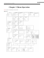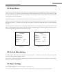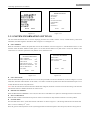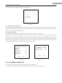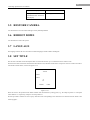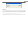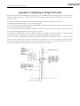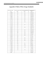
1
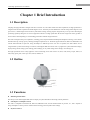
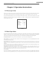
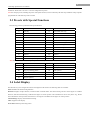
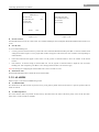
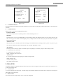
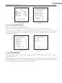
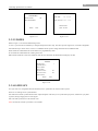
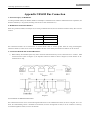
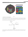
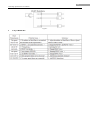
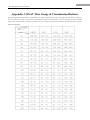
5 Inch High Speed Dome User Manual V2.0.0 2010-01 1 5 Inch High Speed Dome User Manual Thank you for purchasing our product. If there is any question or request, please do not hesitate to contact dealer. This manual is applicable to 5 Inch High Speed Dome. This manual may contain several technically incorrect places or printing errors, and the content is subject to change without notice. The updates will be added into the new version of this manual. We will readily improve or update the products or procedures described in the manual. 2 5 Inch High Speed Dome User Manual Safety Instruction These instructions are intended to ensure that user can use the product correctly to avoid danger or property loss. The precaution measure is divided into “Warnings” and “Cautions”: Warnings: Neglecting any of the warnings may cause serious injury or death. Cautions: Neglecting any of the cautions may cause injury or equipment damage. Warnings Follow these safeguards to prevent serious injury or death. Cautions Follow these precautions to prevent potential injury or material damage. Warnings 1. In the use of the product, you must be strict compliance with the electrical safety regulations of the nation and region. 2. Please use the power adapter, which is provided by normal company. The standard of the power adapter is AC24V/3A. 3. Do not connect several devices to one power adapter as adapter overload may cause over-heat or fire hazard. 4. Please make sure that the plug is firmly connected on the power socket. 5. When the product is installed on wall or ceiling, the device shall be firmly fixed. 6. If smoke, odors or noise rise from the device, turn off the power at once and unplug the power cable, and then please contact the service center. 7. If the product does not work properly, please contact your dealer or the nearest service center. Never attempt to disassemble the camera yourself. (We shall not assume any responsibility for problems caused by unauthorized repair or maintenance.) Warnings 1. Do not drop the dome or subject it to physical shock, and do not expose it to high electromagnetism radiation. Avoid the equipment installation on vibrations surface or places subject to shock (ignorance can cause equipment damage). 2. Do not place the dome in extremely hot, cold (the operating temperature shall be -30°C ~ +65°C), dusty or damp locations, or fire or electrical shock will occur otherwise. 3. The dome cover for indoor use shall be kept from rain and moisture. 4. Exposing the equipment to direct sun light, low ventilation or heat source such as heater or radiator is forbidden (ignorance can cause fire danger). 5. Do not aim the camera at the sun or extra bright places. A blooming or smear may occur otherwise (which is not a malfunction however), and affecting the endurance of CCD at the same time. 6. Please use the provided glove when open up the dome cover, avoid direct contact with the dome cover, because the acidic sweat of the fingers may erode the surface coating of the dome cover. 7. Please use a soft and dry cloth when clean inside and outside surfaces of the dome cover, not to use alkaline detergents. 3 5 Inch High Speed Dome User Manual Table of Contents Table of Contents......................................................................................................................................................... 3 Chapter 1 Brief Introduction........................................................................................................................................ 4 1.1 Description..................................................................................................................................................... 4 1.2 Outline ........................................................................................................................................................... 4 1.3 Functions ....................................................................................................................................................... 4 Chapter 2 Operation Instructions................................................................................................................................. 8 2.1 Power-up Action ............................................................................................................................................ 8 2.2 Basic Operations............................................................................................................................................ 8 2.3 Presets with Special Functions ...................................................................................................................... 9 2.4 Label Display................................................................................................................................................. 9 Chapter 3 Menu Operation ........................................................................................................................................ 10 3.1 Main Menu ...................................................................................................................................................11 3.2 System Information ......................................................................................................................................11 3.3 Dome Settings...............................................................................................................................................11 3.3.1 SYSTEM INFORMATION SETTINGS .......................................................................................... 12 3.3.2 CAMERA SETTINGS...................................................................................................................... 13 3.3.3 MOTION SETTINGS....................................................................................................................... 16 3.3.4 PRESETS.......................................................................................................................................... 17 3.3.5 PATROLS ......................................................................................................................................... 19 3.3.6 TIME TASK...................................................................................................................................... 20 3.3.7 PATTERNS ....................................................................................................................................... 21 3.3.8 PRIVACYS ....................................................................................................................................... 21 ALARMS ................................................................................................................................... 22 3.3.9 AUXS ........................................................................................................................................ 23 3.3.10 3.3.11 CLEAR SETTINGS .................................................................................................................. 24 3.3.12 PASSWORD .............................................................................................................................. 24 ZONES ...................................................................................................................................... 25 3.3.13 LINE SYN ................................................................................................................................. 25 3.3.14 3.4 RESTORE DEFAULTS ............................................................................................................................... 26 3.5 RESTORE CAMERA.................................................................................................................................. 27 3.6 REBOOT DOME......................................................................................................................................... 27 3.7 LANGUAGE ............................................................................................................................................... 27 3.8 SET TITLE .................................................................................................................................................. 27 Appendix 1 Lightning & Surge Protection ................................................................................................................ 29 Appendix 2 RS485 Bus Connection .......................................................................................................................... 30 Appendix 3 24VAC Wire Gauge & Transmission Distance ...................................................................................... 33 Appendix 4 Table of Wire Gauge Standards.............................................................................................................. 34 4 5 Inch High Speed Dome User Manual Chapter 1 Brief Introduction 1.1 Description Adopting the high-performance integral dome drive with auto iris, auto white balance and other capabilities, the high speed dome is integrated with the built-in pan/tilt unit and the digital receiver. The dome provides Manchester code and wiring failure diagnosis; with precise drive, it features high reaction sensitivity and reliable running, ensuring superior image stability; it also provides 3D intelligent positioning capability during the use of client application software. The high speed dome has become a high-tech security product in the surveillance field depending on its outstanding performance and full-integral functions. The dome is designed with power capabilities, including preset, and pan/tilt/frame/random/panorama/pattern scanning; it also features manual limit stops, auto flip, privacy masking, backlight compensation, etc. The dome supports PELCO-D, PELCO-P, PRIVATE-Code, VICON and KALATEL-32 protocols, being self-adaptive to different protocols. For ease of operation, the dome address can be assigned either by DIP switch settings or software; multi-lingual OSD menu allows user to program the system information display, display settings, dome settings, preset settings, pattern settings, privacy mask settings, alarm settings, AUX settings, etc. The high speed dome can be widely applied to various monitoring scenes such as the river, forest, road, railway, airport, harbor, oil field, sentry, plaza, park, scenic spot, street, station, stadium, etc. 1.2 Outline Back Bo x Back Box Dome Drive Bubble 5 Inch High Speed Dome 1.3 Functions Multi-lingual OSD Menu The dome provides multi-lingual OSD menu for display of system information and setting of dome parameters. Self-adaptive to Multiple Protocols The dome is compatible with PELCO-D, PELCO-P, PRIVATE-Code, VICON and KALATEL-32 protocol, etc., and is capable of being self-adaptive to these protocols without need of selecting protocol by DIP switch settings. Keyboard Control 5 5 Inch High Speed Dome User Manual The pan/tilt movement and zoom actions of dome can be controlled by the control keyboard, DVR, matrix, etc. Limit Stops The dome can be programmed to move within the limit stops (left/right, up/down) which are configurable by the control keyboard, DVR or client application software. Auto Scan The dome provides 5 scanning modes: pan scanning, tilt scanning, frame scanning, random scanning and panorama scanning. The scanning speed can be set by OSD menu from level 1 to 40, with the corresponding speed ranging from 1°/second to 40°/second. Preset Freeze Frame This feature freezes the scene on the monitor when going to a preset. This allows for smooth transition from one preset scene to another and also guarantees that masked area will not be revealed when going to a preset. Presets Each of the user-definable presets can be programmed to use pan, tilt, camera settings and other settings. When preset is called, the dome will automatically move to the defined position. User is allowed to add, modify, delete and call each preset. Label Display The on-screen label of the preset title, azimuth/elevation, zoom and other operations can be programmed by menu and displayed on the monitor. Auto Flip In manual tracking mode, when a target object goes directly beneath the dome, the dome will automatically rotate 180 degrees in horizontal direction to maintain continuity of tracking. When the dome rotates (flips), the camera starts moving upward as long as you continue to hold the joystick in the down position. This function can be realized by image center flip depending on different camera models. The feature can be enabled/disabled through the menu. Privacy Mask The privacy mask allows a user to program user-defined areas that cannot be viewed by the operator of the dome system. A masked area will move with pan and tilt functions and automatically adjust in size as the lens zooms telephoto and wide. 3D Intelligent Positioning The speed dome can be controlled with the 2 buttons and scroll of mouse can be used under PRIVATE-Code protocols with devices and client software. Click on a certain area and the device will move to the scene with corresponding point as the center. When a rectangular area is selected by left-clicking the mouse, device will move to its center and enlarge it. With right-clicking, the lens will zoom in, and the scroll can easily make the lens zooming, and mouse operation automatically incorporates zooming effect. Proportional Pan Proportional pan automatically reduces or increases the pan and tilt speeds in proportion to the amount of zoom. At telephoto zoom settings, the pan and tilt speeds will be slower for a given amount of joystick deflection than at wide zoom settings. This keeps the image from moving too fast on the monitor when there is a large amount of zoom. Auto Focus The auto focus enables the camera to focus automatically to maintain clear video images. IR Cut Filter The IR cut filter can be set to Auto, Day and Night. In auto mode, the camera is capable of automatically switching Black & White mode (Night) and Color mode (Day) with regard to environment lightening conditions. In manual switch mode, user can increase sensitivity in low light conditions by switching to Black & White mode, while the Color mode is preferred in normal lighting conditions. Low Light Electronic Shutter The shutter speed will automatically slow down in low illumination conditions to maintain clear video images by extending the exposure time. The feature can be enabled/disabled by the menu. Backlight Compensation (BLC) 6 5 Inch High Speed Dome User Manual If a bright backlight is present, the subjects in the picture may appear dark or as a silhouette. Backlight compensation (BLC) enhances objects in the center of the picture. The dome uses the center of the picture to adjust the iris. If there is a bright light source outside of this area, it will wash out to white. The camera will adjust the iris so that the object in the sensitive area is properly exposed. Wide Dynamic Range (WDR) When the Wide Dynamic Range (WDR) function is on, the dome is able to balance the brightest and darkest sections of a scene to produce a picture that is better balanced in lighting and provides more details. White Balance (WB) This feature automatically processes the viewed image to retain color balance over a color temperature range. The default setting for white balance is AUTO. Patrol The high speed dome provides up to 8 patrols. In each patrol, user is allowed to specify the scanning track by a group of user-defined presets, with the scanning speed between two presets and the dwell time at the preset separately programmable. Pattern A pattern is a memorized, repeating series of pan, tilt, zoom, and preset functions that can be recalled with a command from a controller or automatically by a configured function (alarm, park, time task, or power-up). By default the focus and iris are in auto status during the preset is being memorized. Power-off Memory This feature allows the dome to resume its previous position or status after power is restored. By default setting, the dome supports the power-off memory capability with the dwell time of 3 minutes. Alarm Response Action The speed dome supports 7 alarm inputs which can be set to NO or NC. Upon having received the alarm input signal, the dome will automatically activate a user-defined action, which can be programmed to: preset 1-8, pattern 1-4, patrol 1-8, pan scan, tilt scan, random scan, frame scan, panoramic scan, color/B&W mode or none. After the alarm is cleared, the dome is capable of resuming its previous activity or position. AUX Output An auxiliary output is a configurable signal from the dome back box that can trigger another device to operate. The dome provides two auxiliary outputs: AUX1 andAUX2. The auxiliary output type can be set to NO (normally open) or NC (normally closed) by menu. And the alarm dwell time is configurable as well. Manchester Code Self-test Enable the Manchester code diagnosis capability by setting the positions 4, 5 and 6 of DIP Switch SW2 to ON. During the use of the Manchester code diagnosis, the corresponding fault code will be displayed on the screen (not available during park time). The detailed fault code is defined as below: Fault Code Description E0 Normal control E1 Cable is unconnected E2 E3 E4 E5 The cable is connected, and data can be normally received, but the address analysis is incorrect. The cable is connected, and data can be normally received, but the command analysis is incorrect. The cable is connected, and data can be normally received, but the analysis of address and command is incorrect. The cable is connected, but the received data does not comply with the requirements of Manchester code. 7 5 Inch High Speed Dome User Manual Time Task A time task is a preconfigured action that can be performed automatically at a specific date and time. The programmable actions include: preset 1-8, pattern 1-4, patrol 1-4, pan scan, tilt scan, random scan, frame scan, panorama scan, day/night mode or none. Zone A zone is a pan and tilt area defined by a left/right and up/down limit stops. The dome provides eight zones, each with configurable label and limit stops. If the dome has dwelled at a zone without receiving any command over 4 minutes, this feature will enable the dome to perform panorama scanning within the zone. Password The dome features password protection to prevent unauthorized changes to the dome settings. Camera Title Title text is the label used to identify the camera viewed on the monitor. Up to 15 characters can be used for a title Compass Direction The dome will show the direction when user manually controls it to rotate. The detailed display information is as below: Display Indication N North NE Northeast E East SE Southeast S South SW Southwest W West NW Northwest The azimuth zero indicates the north direction. RS-485 Failure Diagnostics In the presence of failure at the transmitting and receiving terminals of RS-485 communications, the speed dome is capable of performing self-test and detecting the fault results which will be displayed on the screen. Soft Baud Rate The baud rate of dome can be configured by the menu without need of DIP switch settings. 8 5 Inch High Speed Dome User Manual Chapter 2 Operation Instructions 2.1 Power-up Action After the power is applied, the speed dome will perform self-test action that begins with lens actions and then pan and tilt movement. After completion of power-up self-test actions, the interface as shown in Figure 2.1 will be displayed on screen for 120 seconds. The System Information displayed on the screen includes the Dome Address, Protocol, Version and other information. The COM FORM refers to the baud rate, data bit and stop bit of the dome, e.g., “2400, 8, 1” indicates the dome is configured with the baud rate of 2400, 8 data bits and 1 stop bit. TYPE ADDRESS COM FORMAT PROTOCOL VERSION DS- 2AF1-507 0 2400,8,1 AUTO MATCH 2. 10 BUILD DATE 09 11 20 Figure 2.1 2.2 Basic Operations The following operation shall be done with the use of control device or client software. The control devices include control keyboard and DVR, etc. And the client refers to the client application software. Examples are given here for common operation provided that the current control system supports following operation. Please refer to Client Software User Manual for detail operation guide. Pan and tilt movement: move the joystick to the desired direction, or press the Up/Down/Left/Right buttons. Zoom operation: press ZOOM+/TELE button to make the lens closer and magnify the scene. Press ZOOM-/WIDE button to make the lens farther and minify the scene. Focus operation: After FOCUS+/FAR button is pressed, the object far away will become clearer while the object in vicinity will be ambiguous. After FOCUS-/NEAR button is pressed, the object in vicinity will become clearer while the object far away will become ambiguous. In auto focus mode, camera will focus automatically to maintain clear image. This feature can also be achieved by manually as well. However, after other operation of device, camera will resume auto focus. Iris operation: press IRIS+/OPEN to enlarge the iris and increase the image brightness. And by pressing IRIS-/CLOSE, the iris will gradually shrink that decreases image brightness. In auto iris mode, the IRIS+/OPEN and IRIS-/CLOSE buttons are still operable. However, after finishing other operation by dome, camera will resume auto iris action. Preset operation: Preset can be programmed or called through keyboard or menu. The dome provides 256 presets. Press the SHOT button and then the numeric keys to call the programmed preset. E.g., the callup of preset 08 can be achieved by pressing PRESET button and then the 9 5 Inch High Speed Dome User Manual numeral 08. Please refer to Section 3.3.4 for the configuration of presets. Note: the callup of presets, including the presets with special functions, will be restricted by the limit stops if defined. Callup of presets programmed out of the limit stops will be invalid. 2.3 Presets with Special Functions The following presets are predefined with special functions: Call Preset Function Call Preset Function 33 Auto flip 93 Set manual limit stops 34 Pan zero 94 Remote reboot 35 Patrol 1 95 Access main menu 36 Patrol 2 96 Stop a scan 37 Patrol 3 97 Start random scanning 38 Patrol 4 98 Start frame scanning 39 IR cut filter in 99 Start pan scanning 40 IR cut filter out 100 Start tilt scanning 41 Pattern1 101 Start panorama scanning 42 Pattern2 102 Patrol 5 43 Pattern3 103 Patrol 6 44 Pattern4 104 Patrol 7 92 Enable limit stops setting 105 Patrol 8 Note: In Manchester code control, the presets predefined with special functions are shown as below: Set Preset Function Call Preset Function 65 Remote reboot 67 Auto flip 66 Access main menu 70 Start pattern1 69 Stop programming pattern 71 Start pattern2 70 Program pattern1 72 Start pattern3 71 Program pattern2 72 Program pattern3 2.4 Label Display The dome allows you to configure how labels are displayed on the monitor. The following labels are available: Zoom: Identifies the amount of magnification. Direction: Displays compass direction, with the format of NEXXX TXXX. The XXX following NE refers to the degrees in northeast direction, while the XXX following T indicates the degrees in vertical position. The north direction can be set by menu. E.g., NE235 T035 indicates the current position of the dome is in 235 degrees in northeast and 35 degrees in vertical position. Alarm Message: Displays activated alarm message. Time: Support for time display. Preset Title: Identifies preset being called. 10 5 Inch High Speed Dome User Manual Chapter 3 Menu Operation Note: The menu varies depending on camera models. Menu Tree 11 5 Inch High Speed Dome User Manual 3.1 Main Menu In PELCO-P/D or other PTZ protocols, the main menu can be entered by calling preset 95 through DVR, Keyboard or Client Software, as shown in Figure 3.1.1. For instance, press the PTZ button on DVR front panel to enter the PTZ control mode, and then press the REC button followed by numeric 095 to access the main menu; or press the SHOT + numeric 095 and then the Enter button from the control keyboard to access the main menu. In PRIVATE-Code protocol, directly press the Menu button on DVR front panel to access the main menu. Change cursor position through joystick or direction buttons on the front panel of DVR and move the cursor to the selected menu item. Press IRIS+ to confirm, i.e., operation can be done on this menu options. If current menu contains sub-menu, enter the corresponding sub-menu. To perform operation on menu option, the selected number behind menu item can be changed by moving joystick up and down. Press IRIS+ to confirm and return to previous menu. The same procedure is followed for the next operation for which no description is given. Select Exit menu option to confirm and exit from menu operation. MAIN MENUS <SYS INFO> <DOME SETTINGS> <RSTORE DEFAULTS> <RSTORE CAMERA> <RSBOOT DOME> LANGUAGE ENGLISH SET TITLE OFF EXIT Figure 3.1.1 SYS INFO TYPE DS- 2AF1-507 ADDRESS 0 COM FORMAT 2400,8,1 PROTOCOL PELCO-D TEMPERATURE 27 VERSION 2. 10 BUILD DATE 09 11 20 BACK EXIT Figure 3.2.1 3.2 System Information This menu displays current dome system information, as shown in Figure 3.2.1. Information in menu option cannot be changed and Temperature refers to internal temperature of dome. Move the cursor to Back and click IRIS+ to return to the previous menu, or move the cursor to Exit and click IRIS+ to save the settings. Operation is similar to all other submenus. 3.3 Dome Settings Enter the Dome Settings menu, as shown in Figure 3.3.1 and Figure 3.3.2. Note: use the Left and Right direction buttons to enter the next page and back to the previous page of the menu if available. 12 5 Inch High Speed Dome User Manual DOME SETTINGS <PRIVACYS> <ALARMS> <AUXS> <CLEAR SETTINGS> <PASSWORD> <ZONE> <LINESYNC> BACK Figure 3.3.1 EXIT Figure 3.3.2 3.3.1 SYSTEM INFORMATION SETTINGS The SYS INFO SETTINGS menu is used for displaying the dome drive model, software version, available memory, DIP switch information, and other diagnostic information. Refer to Figure 3.3.3 and Figure 3.3.4. SOFT ADDRESS When the soft address is enabled, the speed dome will use the soft address, as shown in Figure3.3.3, with the addresses from 1 to 255 selectable. When the SOFT ADDR ACTIVE option is set to OFF, the hard address set by DIP switch is used; if the address of the control device is 0, then the speed dome of any address can be controlled as well. SYS INFO SETTINGS SOFT ADDRESS 1 SOFT ADDR ACTIVE OFF SOFT BAUD 2400 SOFT BAUD ACTIVE OFF BROADCAST ADDRESS ON PELCO CHECKSUM ON SYS TIME BACK FAN CONTROL BACK TEMP EXIT EXIT Figure 3.3.3 SYS INFO SETTINGS ZERO ANGLE DISPLAY SETTINGS Figure 3.3.4 SOFT BAUD RATE When the SOFT BAUD option from the menu is set to ON, the speed dome will use the soft baud rate, as shown in Figure 3.3.3, with 2400, 4800, 9600 and 19200 selectable. In this status, it is invalid to set baud rate by DIP switch. When the SOFT BAUD option is set to OFF, the baud rate can be set by DIP switch. Note: when the soft baud rate function has been enabled and configured, the dome will reboot to activate the settings; and when the soft baud rate function is disabled, the dome will reboot as well. BROADCAST ADDRESS When the BROADCAST ADDRESS is set to ON, the control device with address 0 is capable of controlling all domes connected to it. PELCO CHECKSUM When the dome in PELCO-P and PELCO-D protocol cannot be controlled, user may enable this function to solve the problem. SYSTEM TIME The SYS TIME allows user to set the date and time of the dome. As shown in Figure 3.3.5, the message indicates the current date and time is 15:33:25 on January 18th , 2007. Move the joystick of the keyboard or use the Left and Right buttons on DVR front panel to select the option, and move the joystick of 13 5 Inch High Speed Dome User Manual the keyboard or use the Up and Down buttons to modify the value. Y- M- D 07 01 18 H- M- S 15 33 25 DONE: OPEN QUIT: OPEN Figure 3.3.5 ZERO ANGLE (North Direction) Enter the ZERO ANGLE(azimuth/elevation) menu and then use the joystick of keyboard or the direction buttons on DVR front panel to define the amount of pan from zero degrees vertical and the amount of tilt from zero degrees horizontal, and finally press the IRIS+ button to save settings and exit the current menu. DISPLAY SETTINGS The DISPLAY SETTINGS menu is displayed in two pages, as shown in Figure 3.3.6 and Figure 3.3.7. Each item can be set with the separate display time on screen from 2sec, 5sec and 10 sec selectable, or set to be ON or OFF. The preset display position can overlapped the display positions of azimuth/elevation and zoom. If both of the ZOOM SHOW and the PT SHOW are set to ON, then in the preset operation status, the preset label will be displayed all the time; while in other operation status, the azimuth/elevation and zoom label are displayed all the time in other status. The external alarm response actions can be activated in non-menu programming mode while disabled in the menu programming mode. DISPLAY SETTINGS ZOOM SHOW 2 PT SHOW 2 ALARM SHOW ON TIME SHOW ON PRESET SHOW ON ZONE SHOW ON BACK DISPLAY SETTINGS ADDRESS SHOW ERROR RATE SHOW EXIT Figure 3.3.6 BACK OFF OFF EXIT Figure 3.3.7 3.3.2 CAMERA SETTINGS Note: different dome models are programmed with different Camera Settings menu. The CAMERA menu is displayed in three pages, as shown in Figure 3.3.8, Figure 3.3.9 and Figure 3.3.10. 14 5 Inch High Speed Dome User Manual CAMERA FOCUS AF ZOOM LIMIT 36 ZOOM SPEED HIGH SLOW SHUTTER ON IRCUT FILTER AUTO D/N LEVEL HIGH SHARPNESS BACK 9 EXIT Figure 3.3.8 Figure 3.3.9 CAMERA WHITE BALANCE AUTO RED 210 BLUE 150 IMAGE FLIP OFF FOCUS LIMIT 1M INIT LENS NOISE REDUCE BACK OFF N/A EXIT Figure 3.3.10 FOCUS The camera provides three focus modes for selection: AF (auto), HAF (half-auto) and MF (manual). In auto focus mode, the camera will allow the lens to remain in focus when using pan, tilt and zoom (PTZ) functions. In manual focus mode, the focus can be operated manually. In half-auto focus mode, the camera will remain in a fixed focus position when all PTZ motions are stopped. And when the PTZ motions are resumed, the camera will focus automatically. The default setting is AF. ZOOM LIMIT Zoom limit allows the user to define a limitation on the amount of telephoto zoom. The settings vary depending on camera model. Zoom amount=optical zoom× digital zoom. When the ZOOM LIMIT is set to the minimum value, it indicates the digital zoom is disabled, and the optical zoom is in its maximum value. ZOOM SPEED Zoom speed allows the user to define the speed at which the dome will go from full wide zoom to the optical zoom, with three levels selectable: HIGH, MID and LOW. The default setting is HIGH. SLOW SHUTTER The shutter will automatically slow down to obtain clearer figure through exposure time extension under low lightening. The default setting is ON. IR CUT FILTER The IR cut filter can be set to AUTO, DAY and NIGHT. In auto mode, the camera is capable of automatically switching Black & White mode (NIGHT) and Color mode (DAY) with regard to environment lightening conditions. In manual switch mode, user can increase sensitivity in low light conditions by switching to Black & White mode, while the Color mode is preferred in normal lighting conditions. The default setting is AUTO. 15 5 Inch High Speed Dome User Manual The DAY mode can be set by calling preset 39, and the NIGHT mode set by preset40. D/N Level The D/N level is the light level at which the IR cut filter switches DAY or NIGHT. Three levels are selectable: HIGH, MID and LOW. The default setting is MID. Note: This feature varies depending on camera model. Sharpness The sharpness function enhances picture detail by increasing the aperture gain of the camera and sharpening the edges in the picture. Levels from 1 to 16 are selectable, with the default setting of level 9. BLC/WDR If a bright backlight is present, the subjects in the picture may appear dark or as a silhouette. Backlight compensation (BLC) enhances objects in the center of the picture. The dome uses the center of the picture to adjust the iris. If there is a bright light source outside of this area, it will wash out to white. The camera will adjust the iris so that the object in the sensitive area is properly exposed. When the Wide Dynamic Range (WDR) function is on, the dome is able to balance the brightest and darkest sections of a scene to produce a picture that is better balanced in lighting and provides more details. Note: The BLC/WDR feature varies depending on camera model. The default setting is for BLC function. BLC LEVEL This feature is used for adjusting the backlight compensation level. Note: The feature varies depending on camera model. AE MODE The AE mode can be set to AUTO, IRIS, SHUTTER, GAIN or MANUAL. When it is set to AUTO, the auto iris, auto shutter and auto gain functions are all enabled; when it is set to IRIS, the iris function adopts the defined value while the auto shutter and auto gain remain to be enabled; when it is set to SHUTTER, the shutter function adopts the defined value while the auto iris and auto gain remain to be enabled; and when it is set to GAIN or MANUAL, the gain value can be adjusted, or the iris, gain and shutter values are all adjustable. The default setting is AUTO. Note: The Gain or Manual feature varies depending on camera model. IRIS The iris is the lens function that opens and closes the iris in response to changing light conditions, with the numeric values from 0 to 17 selectable. SHUTTER The Shutter is the duration of the electronic shutter. User can set the shutter speed to 1, 2, 4, 8, 15, 30, 60, 125, 180, 250, 500, 1000, 2000, 4000 or 10000. The numeric value of X indicates the shutter speed is 1/X second. GAIN The Gain indicates the amplification degree of the original image signal, with the numeric values from 0 to 15 selectable. EXPOSURE COMP The exposure compensation effect can be adjusted through exposure volume adjustment. The numeric values from 0 to 14 are selectable, with the default setting of 7. WHITE BALANCE This feature automatically processes the viewed image to retain color balance over a color temperature range. The dome provides 5 modes for selection: AUTO, INDOOR, OUTDOOR, SELFDEF (self-defined) and ATW. When the SELFDEF is selected, set the value of RED and BLUE. IMAGE FLIP This feature allows the video image to be mirrored on the screen. FOCUS LIMIT The focus limit can be set to 1CM, 30CM, 1M or 3M. The feature allows the camera to perform auto focus out of the focus limit . The 16 5 Inch High Speed Dome User Manual default setting is 1M. INIT LENS This feature enables the camera to perform daily lens initiation action to ensure the normal operation. NOISE REDUCE The noise reduce function can be set to OFF, HIGH, MID and LOW. The default setting is MID. Note: This feature varies depending on camera model. 3.3.3 MOTION SETTINGS The MOTION menu is displayed in two pages, as shown in Figure 3.3.11 and Figure 3.3.12. MOTION AUTO FLIP ON PROPORTIONAL PAN OFF PARK TIME 5 PARK ACT NONE SCAN SPEED 40 IMAGE FREEZE DOME SPEED BACK OFF MID EXIT Figure 3.3.11 Figure 3.3.12 ATUO FLIP The dome will rotate 180 degrees when the camera tilts downward and goes just beyond the vertical position. When the dome rotates (flips), the camera starts moving upward as long as you continue to hold the joystick in the down position. Once you let go of the joystick after the dome rotates, joystick control returns to normal operation. The auto-flip feature is useful for following a person who passes directly beneath the dome. This function can be realized by image center flip depending on different camera models. PROPORTIONAL PAN When the PROPORTIONAL PAN is set to ON, the dome will automatically reduce or increases the pan and tilt speeds in proportion to the amount of zoom. At telephoto pan and tilt speeds will be slower for a given amount of joystick deflection than at wide zoom settings. This keeps the image fast on the monitor when there is a large amount of zoom. When the PROPORTIONAL PAN is set to OFF, it will be difficult to trace the object at low pan and tilt speeds or no movement in large amount of zoom. Note: This feature is enabled all the time while setting the patterns. PARK TIME This feature allows the dome to begin a specified operation (scan, preset, or pattern) after a configured period of inactivity. Park time can be configured from 5 to 720 seconds. Note: If no control signal is received for a period of time under the following circumstances, no automatic actions will be performed: 1. In the process of performing dome actions by callup of special presets; 2. In the process of performing external alarm response actions. PARK ACTION This feature will define the activity when the dome parks. The selectable park actions include: presets1-8, patterns 1-4, patrols 1-8, pan scan, tilt scan, random scan, frame scan, panoramic scan, day mode, night mode, or none. SCAN SPEED Scan speed is the degrees per second of the pan scan, tilt scan, frame scan, random scan and panoramic scan. Scan speed is adjustable 17 5 Inch High Speed Dome User Manual from 1 to 40 degrees per second through the camera menu. IMAGE FREEZE This feature freezes the scene on the monitor when going to a preset. This allows for smooth transition from one preset scene to another. Preset freeze frame also reduces bandwidth when used with digital network systems and guarantees that blanked areas will not be revealed when going to a preset. DOME SPEED The manual dome movement speed can be set to HIGH, MID or LOW. PRESET SPEED The speed of preset callup can be set from level 1 to 8. The higher level corresponds to the faster preset callup. LIMIT STOPS Limit stops are configurable stops that limit the pan and tilt range of the dome. There may be left/right and up/down limit stops configurable to define an area. When the LIMIT STOP function is set to OFF, the movement of dome will not be limited despite of defined limit stops. SETTING LIMIT STOPS To set limit stops manually: 1. Enter the SETTING STOPS menu. 2. Follow the directions (SET LEFT LIMIT) displayed on the monitor and use the joystick or the direction buttons on DVR front panel to the desired location of left limit stop. 3. Press the IRIS + button to finish the setting of left limit stop. 4. Follow the same steps to set the right, up and down limit stops in sequence according to the directions displayed on the monitor. The new settings of limit stops will overwrite the existed settings. CLEAR STOPS The defined limit stops can be cleared by this menu. 3.3.4 PRESETS The PRESETS menu is displayed as shown in Figure 3.3.13 PRESETS PRESET NUM [UNDEFINED] 1 <EDIT LABEL> <PRESET PTZ> CLEAR PRESET BACK EXIT Figure 3.3.13 PREST NUMBER The dome provides 256 presets. The PRESET NUM displays the preset under current operation. If the preset has been defined, the corresponding number will appear; while no preset is defined, it will display UNDEFINED. The presets which are predefined for specific functions will not be displayed and no change is allowable. Please refer to page 9 for presets with specific functions. EDIT LABEL 18 5 Inch High Speed Dome User Manual Figure 3.3.14 The Preset Label menu is shown in Figure 3.3.14. Operate the following stops to edit the preset label: a. Move the cursor beside [PRESET]. b. Press the FOCUS+ button to switch input characters among numbers, lowercases, capitals and symbols. Refer to Figure3.3.15. Move the Left and Right buttons to position the cursor beside a character and press FOCUS+ to enter selection. c. To clear a character, use the FOCUS- button to position the cursor under the character to be deleted, and then press ZOOM+. To modify a character, use the FOCUS- button to position the cursor under the character to be modified, and then enter the new character by following Step b. d. When label is completed, press IRIS+ to save the current settings and return to the previous menu. Use the following functions buttons on the keyboard or the DVR front panel to edit preset label: ZOOM-: switch between INS and OVR mode. INS: insert character at the position of cursor; OVR: enter the character at the position of cursor and overwrite the original character. ZOOM+: delete the character at the position of cursor. FOCUS+: switch input characters among numbers, lowercases, capitals and symbols. FOCUS-: move the cursor at the preset label. IRIS+: Confirm and save the current settings and return to the previous menu. IRIS-: Cancel the current operation and return to the previous menu. Direction Buttons: move the cursor to select the numbers/lowercases/capitals / symbols. Figure 3.3.15 PRESET PTZ Enter the PRESET PTZ menu to edit preset scene. Use the joystick or direction buttons to move PTZ to the desired scene and then press the IRIS+ to confirm the settings and return to the previous menu, or press IRIS- to cancel settings. 19 5 Inch High Speed Dome User Manual Note: the setting of preset scene will be restricted by the limit stops if defined. CLEAR PRESET This feature is used for clearing the current preset. 3.3.5 PATROLS The PATROLS settings menu is shown in Figure 3.3.16. PATROLS NUMBER The number of patrol under current operation. The dome provides 8 patrols numbering from 1 to 8. PATROLS PATROL NUM 1 EDIT PATROL PREVIEW DELE PATH BACK EXIT Figure 3.3.16 Figure 3.3.17 EDIT PATROL The EDIT PATROL settings menu is shown in Figure 3.3.17. A patrol can be configured with 32 presets. To edit a patrol: 1. Move the joystick up and down or Up and Down direction buttons to select the preset to be edited. 2. Move the joystick left and right or Left and Right direction buttons to select among PRESET, DWELL TIME and SPEED. 3. After having selected the item to be edited, move the joystick up and down or Up and Down direction buttons to set values. 4. Follow the same steps to edit the other presets. Use the joystick or the Right direction button to enter the next page. The preset edited in the patrol can be modified or deleted as well. In default setting, the preset number is initialized as 0, dwell time is 6 seconds (0-30 seconds selectable) and the patrol speed is level 30 (level 1-40 selectable). 5. Press IRIS+ to save the current settings or press IRIS- to cancel settings and return to the previous menu. Note: the patrol speed of the dome is shown as below: Level 1 4 7 10 13 16 19 22 25 28 31 34 37 40 Speed(°/s) 0.3 6 12 18 30 45 60 80 110 140 170 230 290 350 Level 2 5 8 11 14 17 20 23 26 29 32 35 38 Speed(°/s) 2 8 14 20 35 50 65 90 120 150 190 250 310 Level 3 6 9 12 15 18 21 24 27 30 33 36 39 Speed(°/s) 4 10 16 25 40 55 70 100 130 160 210 270 330 PREVIEW PATROL Enter the PREVIEW menu to view the current patrol if defined, which enables the dome to scan among the presets as predefined. 20 5 Inch High Speed Dome User Manual DELETE PATROL Enter the DELE PATH menu to delete the current patrol. 3.3.6 TIME TASK A task is a preconfigured camera action that can be performed automatically at a specific date and time. The TIME TASK settings menu is shown in Figure 3.3.18: TIME TASK TASK NUM 1 TASK STATE ON TASK ACTION NONE TASK TIME TASK PREVIEW TASK CLEAN BACK EXIT Figure 3.3.18 TASK NUMBER The number of task to be configured. Move the joystick up and down or Up and Down direction buttons to select from number1 to8. TASK STATE Set the task function to be ON or OFF. TASK ACTION This feature defines the activity the dome will perform at the specific time. The selectable actions include: presets1-8, patterns 1-4, patrols 1-8, pan scan, tilt scan, random scan, frame scan, panoramic scan, day mode, night mode, or none. TASK TIME Refer to Figure 3.3.19 for time task settings: Figure 3.3.19 Figure 3.3.20 Use the joystick or Left and Right buttons to position the cursor beside WEEK, START (H-M) or END (H-M), and then use the joystick or Up and Down buttons to select the specific day or time. The weekday can be set to be from Monday to Sunday or Whole Week. TASK PREVIEW Enter the TASK PREVIEW menu to view the time, action and state of the current task defined. Refer to Figure 3.3.20. TASK CLEAN 21 5 Inch High Speed Dome User Manual Enter the TASK CLEAN menu to delete the time and action of the current task. 3.3.7 PATTERNS A pattern is a memorized, repeating series of pan, tilt, zoom, and preset functions that can be recalled with a command from a controller or automatically by a configured function (alarm, park, time task, or power-up). Refer to Figure 3.3.21 for the PATTERNS settings menu: REMAIN MEMORY 100 DONE: OPEN QUIT: CLOSE Figure 3.3.21 Figure 3.3.22 PATTERN NUMBER The number of pattern under current operation. The dome provides 4 patterns numbering from 1 to 4. EDIT PATTERN Enter the EDIT PATTERN menu, as shown in Figure 3.3.22. Operate camera functions to configure the pattern. The REMAIN MEMORY indicates the memory available to configure the patterns. When it displays 0, no patterns can be memorized any more. Note: When configuring and calling the pattern, the auto flip will be valid; and the pan/tilt movement and the lens operation cannot be memorized simultaneously. PREVIEW Enter the PREVIEW menu to view the current pattern which has been defined. DELETE PATTERN Enter the DELE PATTERN menu to delete the current pattern. Note: The deletion of the current pattern will cause its following pattern to be deleted as well, e.g., if the pattern 2 is being deleted, then pattern 3 and pattern 4 will be deleted as well. 3.3.8 PRIVACYS The window blanking allows a user to configure the four-sided areas that cannot be viewed by the operator of the dome system. A blanked area will move with pan and tilt functions and automatically adjust in size as the lens zooms telephoto and wide. Refer to Figure 3.3.23 for the PRIVACYS settings menu. BLANK NUMBER The number of window blank under current operation. The dome provides user-defined 24 window blanks numbering from 1 to 24, and up to 8 windows can be configured at the same image. Specific number of available window blanks varies depending on camera model. 22 5 Inch High Speed Dome User Manual PRIVACYS BLANK NUM 1 BLANK STATUS OFF ADJUST BLANK POS FOCUS+SHIFT STATUS SET BLANK SAVE: OPEN DELE BLANK QUIT: CLOSE BACK EXIT Figure 3.3.23 Figure 3.3.24 BLANK STATUS The BLANK STATUS can be set to ON or OFF. If no window blanking has been configured, then the BLANK STATUS cannot be set to ON. SET BLANK To set a window blanking area: 1. Use the joystick or direction buttons to position the cursor beside SET BLANK and then press IRIS+ to enter the window blank setting menu. Refer to Figure 3.3.24. A purple smear window will appear on the screen (the color of window varies depending on camera models). 2. Follow the instructions that appear on the screen. Use the joystick or direction buttons to move the window to the desired location. 3. Press FOCUS+ to start the setting of window blank size. Use the joystick or direction buttons to adjust the size of window blanking area. After completion, press IRIS+ to save settings, and the window color will turn to gray. Note: The tilt range for configuring the window blank area is from 0~70°and 110~180°. DELETE BLANK Enter the DELE BLANK menu to delete the current window blank. 3.3.9 ALARMS Refer to Figure 3.3.25 for the ALARMS settings menu. ALARM RESUME This mode allows the dome resume its previous activity (scan, pattern, pan/tilt and zoom movement, or previous position) after all alarms are cleared. ALARM SEQUENCE This is the time the dome will perform an alarm activity when more than one alarm of the same priority occurs at the same time. Values from 1 to 200 seconds are selectable. 23 5 Inch High Speed Dome User Manual ALARM SETTING ALARM ALARM RESUME ON ALARM NUM ALARM SEQUENCE 5 ALARM REST DELAY 5 ALARM ACTION AUX NONE NONE ALARM INPUT OPEN ALARM SETTING BACK EXIT BACK Figure 3.3.25 1 PRIORITY HIGH EXIT Figure 3.3.26 ALARM REST DELAY This is the amount of time the dome considers the alarm to be active after it has physically cleared. Values from 0 to 300 seconds are selectable. ALARM SETTING Refer to Figure 3.3.26 for the ALARM SETTING menu. ALARM NUMBER The number of alarm to be set. The dome provides 7 alarms numbering from 1 to 7. PRIORITY The alarm priority can be set to HIGH, MID or LOW. If multiple alarms with different priorities are active at the same time, the dome will only go to the alarms with the highest priority. If multiple alarms with the same priority, then the dome will perform alarm sequence function. ALARM ACTION When an alarm occurs, an input signal to the dome triggers user-defined actions, including presets1-8, pattern 1-4, patrol 1-8, pan scan, tilt scan, random scan, frame scan, panoramic scan, day mode, night mode, or none. AUX OUTPUT The dome provides 2 auxiliary outputs, each alarm output corresponding to one auxiliary output. Available settings include: 1: An alarm action will close AUX1. 2: An alarm action will close AUX2. NONE: No auxiliary will be activated. ALARM INPUT It is used for defining alarm input signal type. Available settings include: OPEN: Normally open. CLOSE: Normally closed. OFF: Disable the alarm input. 3.3.10 AUXS An auxiliary output is a configurable signal from the dome back box that can trigger another device to operate. Refer to Figure 3.3.27 for the AUXS settings menu. AUX OUTPUT It is used for defining alarm output type. Available settings include OPEN (default) and CLOSE, which correspond to normally open and normally closed respectively. DWELL TIME The duration of the AUX output signal, with 0~60 seconds configurable. 24 5 Inch High Speed Dome User Manual CLEAR SETTINGS CLEAR ALL PRESETS CLEAR ALL PATROLS CLEAR ALL PATTERNS CLEAR ALL BLANKS CLEAR ALL ZONES CLEAR ALL TIME TASKS <DIAGNOSTICS> BACK Figure 3.3.27 EXIT Figure 3.3.28 3.3.11 CLEAR SETTINGS Refer to Figure 3.3.28 for the CLEAR SETTINGS menu. Use this menu to clear all user-defined settings, including presets, patrols, patterns, window blanks, zones and time tasks. As shown in Figure 3.3.29 and Figure 3.3.30, the dome provides self-diagnostics function for the occurrence frequency of the following events: high temperature (>65℃), low temperature (<25℃), video loss, low voltage, abnormal reboot, pan sync loss, tilt sync loss and camera sync loss. DIAGNOSTICS HIGH TEMP HIGHEST TEMP LOW TEMP DIAGNOSTICS 0 PAN LOST 0 35°C TILT LOST 0 CAMERA LOST 0 0 LOWEST TEMP 14°C VIDEO LOSS 0 LOW VOLATE 0 POWER UP BACK 0 EXIT Figure 3.3.29 BACK EXIT Figure 3.3.30 3.3.12 PASSWORD The password protection feature is provided to prevent unauthorized changes to the dome settings. Refer to Figure 3.3.31 for the PASSWORD settings menu. Set the START USING to ON or OFF to enable or disable the password protection function. Select the EDIT PASSWORD to enter the menu as shown in Figure 3.3.32. Use the joystick or direction buttons to move the cursor and select the number to be entered. Input the same password again and finally press the IRIS+ to save the password settings. 25 5 Inch High Speed Dome User Manual PASSWORD START USING INPUT PW ON EDIT PASSWORD BACK 1 2 3 4 5 6 INPUT PW AG 1 2 3 4 5 6 DONE: OPEN QUIT: CLOSE EXIT Figure 3.3.31 Figure 3.3.32 3.3.13 ZONES Refer to Figure 3.3.33 for the ZONES settings menu. A zone is a pan and tilt area defined by a left/right and up/down limit stops. The dome provides eight zones, each with configurable label and limit stops. Please refer to section 3.3.4 PRESETS for the specific settings of EDIT LALE and EDIT ZONE. ZONE STATUS: enable/disable the current status to be programmed by menu. SCAN STATUS: enable/disable the scanning in the zone. DELE ZONE: delete the current zone if defined. After the zone id deleted, the ZONE STATUS displays as OFF. ZONES ZONE NUM [UNDEFINED ] EDIT LABEL EDIT ZONE ZONE STATUS SCAN STATUS DELE ZONE BACK 1 ON ON EXIT Figure 3.3.33 3.3.14 LINE SYN Line sync refers to a configurable function that allows user to synchronize all cameras within a system. There are two settings for line synchronization: ON: Enable the external synchronization feature. Adjust the phase of the line sync to synchronize input power, with the line sync phase (V-phase) settings ranging from 0 to 255 degrees. OFF: The dome synchronizes to the internal clock. Note: currently the external sync feature is not available. 26 5 Inch High Speed Dome User Manual LINE SYNC LINE LOCK ON V-PHASE 0 BACK EXIT Figure 3.3.34 3.4 RESTORE DEFAULTS Use this function to reset all dome settings to factory default parameters, including: Dome Address 0 Baud Rate 2400bps 120Ω matching resistance Off Soft Address Off Azimuth Zero Zero angle Auto Focus Auto Zoom Limit Max Optical Zoom Zoom Speed High Low Light Limit On IR Cut Filter Auto Backlight Comp Off AE Mode Auto Exposure Comp 7 White Balance Auto Auto Flip On Proportion Pan On Park Time 5 seconds Park Action None Scan speed 28 °/second Preset Image Freeze Off Limit Stops Off Alarm Resume On Alarm Sequence 5 seconds Alarm Rest Delay 5 seconds Alarm Inputs Off AUX1/AUX2 NO AUX1/AUX2 Dwell Time 5 second Alarm Display On 27 5 Inch High Speed Dome User Manual Time Display Display Off of Display for 2 seconds Zoom, Azimuth/Elevation and Preset Label display 3.5 RESTORE CAMERA Use this function to reset all camera settings to factory default parameters 3.6 REBOOT DOME Use this function to reboot the system. 3.7 LANGUAGE The language used for the on-screen menus. Available languages include Chinese and English. 3.8 SET TITLE The title text is the label used to identify the dome viewed on the monitor. Up to 15 characters can be used for a title. Enter the main menu of the dome and select the SET TITLE to ON, and then exit the menu. Call preset11 for twice within 5 seconds to enter the SET TITLE menu, as shown in Figure 3.3.35. TITLE CODE TITLE BACK EXIT Figure 3.3.35 Move the cursor to the position beside TITLE and then enter the character by calling preset, e.g., the callup of presets 1-9 correspond to the numbers 1-9 respectively, and preset 10 corresponds to 0. We have provided a software for users to query about the codes corresponding to the characters to be entered in the title. Refer to the following figure: 28 5 Inch High Speed Dome User Manual Figure 3.3.38 For example, enter the characters HALL in the text box and click OK. The corresponding codes (0227-0220-0231-0231) will appear in the following text box. In the SET TITLE menu, call preset 10, preset 2, preset2, preset7, preset 10, preset 2…preset 10 in sequence, and the corresponding numerals, characters and position message will appear on the screen. Call preset 16 to delete the character at current position. Call preset 12 for twice within 5 seconds to exit the title settings and display the title at the lower right corner; call preset 13 for twice within 5 seconds to exit the title settings and display the title at the lower left corner; call preset 14 for twice within 5 seconds to exit the title settings and display the title at the upper left corner; and call preset 15 for twice within 5 seconds to exit the title settings and display the title at the upper right corner. After exit from the SET TITLE menu, calling preset 12 for twice within 5 seconds will delete the defined title and not display the title on the screen. 29 5 Inch High Speed Dome User Manual Appendix 1 Lightning & Surge Protection This product adopts TVS plate lightning protection technology to avoid damage caused by pulse signal that is below 3000W, like instantaneous lighting, surging, etc. According to the actual situation outdoors, necessary protection measures must be taken to secure the electrical safety. 1. The distance between signal transmission line and High-voltage equipment or high-voltage cable is at least 50m. 2. Outdoor wiring should better be along the eaves as much as possible. 3. In the open field, wiring should be buried underground in sealed steel pipe, and the steel-pipe should be one-point grounding. Overhead routing method is forbidden. 4. In strong thunderstorm area or high induction voltage areas (such as high-voltage transformer substation), high power lightning protection apparatus and lightning conductor are necessary to be appended. 5. The design for installation and wiring with lightning protection and grounding in mind should be combined with the lightning protection consideration of the building, and conform to the related national standards and industry standards. 6. The system should be equipotentially grounded, and the grounding equipment must satisfy double-request of system anti-jamming and electric safety, and it must not appear short circuit and open circuit with the zero conductor of strong grid. When the system is grounding individual, the resistance should be no more than 4Ω, the section al area of the grounding cable should be no less than 25mm2. For grounding instructions, please refer to the Installation Manual of Speed Dome. 30 5 Inch High Speed Dome User Manual Appendix 2 RS485 Bus Connection 1. General Property of RS485 Bus According to RS485 industry bus standard, RS485 is a half-duplex communication bus which has 120Ω characteristic impendence, the maximum load ability is 32 payloads (including controller device and controlled device). 2. RS485 Bus Transmission Distance When using 0.56mm (24AWG) twisted-pair line, according to different baud rate, the max transmission distance theory table is shown as below: Baud Rate Max Distance 2400BPS 1800m 4800BPS 1200m 9600BPS 800m The transmission distance will be decreased if we use the thinner cable, or use this product under the strong electromagnetic interference situation, or there are lots of devices are added to the bus; on the contrary, the transmission distance will be increased. 3. Connection Method and Terminal Resistance 1) RS485 industry bus standard require daisy-chain connection method between any devices, both sides have to connect a 120Ω terminal resistance (show as Diagram 1), the simplified connection method is shown as diagram 2, but the distance of “D” should not be too long. Diagram 1 Diagram 2 2) Connection of 120Ω terminal resistor The 120Ω terminal resistor can be connected through the DIP switch on the communications board, as shown in Figure3. For a new dome, the 120Ω matching resistor is defaulted as unconnected, switch on the eighth bit of SW2, it will be connected. Conversely, switch off the eighth bit of SW2, it will be unconnected. 31 5 Inch High Speed Dome User Manual Figure 3 4. Problems in the Practical Application Normally, users adopt star-shape connection method in construction, under this situation, the terminal resistors must be connected between two farthest devices (as Figure 4, 1# and 15#), but this connection method is not satisfy the requirement of the RS485 industry standard so that it will lead to some problems such as signal reflection, anti-jamming ability decline when the devices are faraway. At this time, the dome will be uncontrollable, or self-running, etc. Figure 4 For such case, the best way is adding a RS485 distributor. This product can effectively change the star-shape connection to which satisfies the requirement of RS485 industry standard, in order to avoid those problems and improve the communication reliability. Show as figure 5. 32 5 Inch High Speed Dome User Manual Figure 5 4 FAQ of RS485 Bus 33 5 Inch High Speed Dome User Manual Appendix 3 24VAC Wire Gauge & Transmission Distance The following table has described the recommended max. distance adopted for the certain wire gauge when the 24VAC voltage loss rate is less than 10%. For the AC driven device, the maximum voltage loss rate allowable is 10%. For example, for a device with the rating power of 80VA which is installed at a distance of 35 feet (10m) away from the transformer, then the minimum wire gauge required is 0.8000mm. Distance feet(m) Wire Gauge mm Power (va) 34 5 Inch High Speed Dome User Manual Appendix 4 Table of Wire Gauge Standards Bare Wire Gauge (mm) Americ an Wire Gage (Brit ish)Standard Wire G auge Cross-sectional Area ofBare Wire AWG SWG mm 2