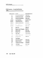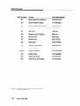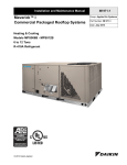
1
AT&T 824-102-142
Issue 3
May 1992
Switched Access Remotd ,.’I
Test System. (SARTS)
TA201 :XL
Technical Description
Copyright
G: 1992 AT&T
All Rights Reserved
Printed in U.S.A.
Notice
of Disclaimer
This Technical Specification is published by AT&T to inform the industry of the interface between Switched
Access Remote Test System (SARTS) and the Bell Communications Research, Inc. (Bellcore) Technical
Reference TR-TSY-000834 for remote access and testing of Special Services. It is a preliminary document
subject to review and changes. As such, future issues of this information may differ in content and format.
AT&T MAKES NO REPRESENTATION OR WARRANTY, EXPRESS OR IMPLIED, WITH RESPECT TO
THE SUFFICIENCY, ACCURACY, OR UTILITY OF ANY INFORMATION OR OPINION CONTAINED
HEREIN. AT&T EXPRESSLY ADVISES THAT ANY USE OF OR RELIANCE UPON SAID INFORMATION
OR OPINION IS AT THE RISK OF THE USER AND THAT AT&T SHALL NOT BE LIABLE FOR ANY
DAMAGE OR INJURY INCURRED BY ANY PERSON ARISING OUT OF THE SUFFICIENCY,
ACCURACY, OR UTILITY OF ANY INFORMATION OR OPINION CONTAINED HEREIN.
This document is not to be construed as a suggestion to any manufacturer to modify or change any of its
products.
Readers are specifically advised that each BOC* vendor, or Regional affiliate thereof may have
requirements or specifications different from the generic descriptions herein. Therefore, any purchasers,
vendors, or mrs
of products should communicae direct@ with the vendor, BOC, or Regional
affiliate thereof to ascerfain their needs, specificatiaw, and actual requiremen& .
If further information regarding technical content is required, please forward correspondence to:
Product Manager - SARTSTTA201:XL
AT&T
490 Red Hill Road
Room HR 2H-192
Middletown, NJ 07749
l-800-932-2273
Federal
Communications
Commission
(FCC) Statement
Warning:
This equipment has been certified to comply with the limite for a Claee A
computbtg device, punuant to Subpart J of Part 15 of FCC Rulea. Only
pwlplwmlr (computer inputb@ut
devbe, terminels, B
etc.) certified to
com@ywfththeClaeeAlimbmybe
*~?g=w~&
, ’ .’
..
t ‘..I>
;f-. ._
,;
. w*F.gf
- 3fv.r
m;
Your 382 computer generates radio frequency energy and should not be turned on unless the cover and
filler plates are installed and securely fastened. If your 382 computer is not instaUed and used according to
the manufacturer’s instnxtkms in this manual, it can interfere wfth nearby radio and television reception.
The operator must then take whatever steps are necessary to correct the interference.
?
Trademarks
VAX is a trademark of Digital Equipment Corporation.
COMMON LANGUAGE is a registered trademark and CLEI, CLLI, CLCI, and CLFI are trademarks
Communications Research. Inc.
Ordering
Information
The ordering number for this document is 824-102-142. To order this document, call l-800-432-6600.
more ordering information, refer to “Ordering Information” in the “About This Document” section.
Support
of Bell
Telephone
For
Nuz?her
AT&T Provides a telephone number for you to use to report errors or to ask questions about the information
in this document. The support telephone numbers are l-800 334-0404 (outside North Carolina) or l-91 9
727-6681 (inside North Carolina).
Developed by the AT&T Document Development
-. “’
Organization.
IF-
.,
Contents
About This Document
n
n
n
n
n
l
n
1
xi
xi
xi
x ii
x ii
...
Purpose/Scope
Intended Audiences
Reasons for Reissue
SARTS TA201 :XL Translator
How to Use This Document
Related Documentation/Training
How to Order Documentation
XIII
x iv
xv
System Description
1-l
m Technical Reference Overview
n interfaces
n TA201 :XL Capacity
m SARTSTA201 :XL Command Translation
1-l
l-2
1-4
1-6
SARTS Commands
2-l
Introduction
m DDS Services - Digital Testing
n DDS Services - Loop Qualification
n HCDS Services Testing
m Voiceband Testing Commands
2-1
2-2
2-28
2-58
2-77
n
TR-TSY-000834 Command
Supported by TA201:XL
n
Tests
Options Not
General
Issue 3 May 1992
v
Contents
4
Notice of Modification
n
n
IN
vi
General
TA201 :XL Enhancement
Index
Issue 3 May 1992
or Change
4-l
Requests
4-I
4-2
IN-I
Figures
1
System Description
l-l.
SARTS TA201 :XL Translator Link
Alternatives
1-5
Issue 3 May 1992
vii
,..c.
Ii
Tables
1
System Description
l-1.
TA201 :XL Translator Link Descriptions
1-4
issue 3 May 1992
ix
About This Document
Pumose/Scot3e
This AT&T manual is published as a guide to Test System Controllers and
Remote Test Units (TSCRTU) that interface with Switched Access Remote Test
System (SARTS), through the TA201 :XL Translator, for remote accessing and
testing of:
n
Voiceband Special Services circuits
n
Voiceband data circuits
n
Digital Data System circuits
n
High Capacity Digital Services (DSl).
In particular, this document describes the SARTS commands and the
corresponding TR-TSY-000834 messages that support the access and test
functions.
..
Intended Audiences
The intended audiences are the purchasers and suppliers of Test System
Controllers and Remote Test Units (TSC/RTU) that interface with SARTS
through the TA201 :XL Translator.
Issue 3 May 1992
xi
About This Document
Reasons for Reissue
This issue is required to update Chapter 2 “SARTS COMMANDS.” The
changes reflect updates and changes in SARTWA201 :XL capabilities to
perform specific tests. Changes were made to the capabilities of existing
commands (no new commands).
Specifically, the 704 command was added to DDS Services-Digital Testing and
the 706 command was added to DDS Services-Loopback Qualification Tests.
Several commands are explained in more detail.
SARTS TA201:XL Translator
Standard interfaces are the key element of an open architecture that will support
control of generic test system controllers by Operations Systems such as
SARTS. Standard interfaces allow you to buy equipment and systems from
different vendors, choosing what best suits your operating needs.
This flexibility can be provided only through an open architecture that adheres to
international standards. AT&T firmly supports the development of standards as
the key element of open architectures.
To make this open architecture a reality, we are taking the following steps:
n
Facilitating the rapid specification of standard interfaces and protocols by
the Tl Ml committee, which has been chartered to develop standards for
the U.S. telecommunications industry.
n
Meeting standards specified by Tl Ml as soon as possible for every
system to which they apply.
m
Reviewing Technical References (TRs) with Bellcore, consistent with
operating company and AT&T interests, in order to present mutually
acceptable positions to Tl Ml.
In addition to standard interfaces that meet Tl Ml requirements, AT&T plans to
offer interfaces based on Bellcore technical advisories (TAs) and technical
references (TRs). This announcement describes a planned interface between
SARTS and generic Test System Controller/Remote Test Units (TSC/RTUs).
The protocol for this interface was originally specified by the TA-TSY-000201.
This advisory has been incorporated in Technical Reference, TR-TSY-000834.
Process controllers and TSC/RTUs conforming to the standard interface will
allow you to mix and match remote testing and measurement equipment from
multiple vendors.
xii
Issue 3 May 1992
About This Document
--
How to Use This Document
This document covers the SARTS commands and TR-TSY-000834 messages
passing across the TA201 :XL interface between SARTS and the TSC/RTU. It
also highlights any command options not supported by the TA201 :XL Translator.
The subjects in each chapter are broken down as follows:
m Chapter 1, System Description: Provides a brief description of the function
that the TA201 :XL Translator provides SARTS as follows:
-
Description of the interface from the TA201 :XL Translator to the
SARTS PC.
-
Description of the interface from the TA201 :XL Translator to the
various TSCs.
-
TA201 :XL Translator capacity.
-
Detailed tables of SARTS commands with their corresponding
TSY-00834 messages that are supported by the TA201 :XL
Translator.
TR-
m Chapter 2, SARTS Commands: Provides the commands used at the
SARTS Test Positions with respect to TA201 :XL remote access/testing
capabilities. The commands are broken down into the following categories:
-
DDS Command Set.
-
DDS Loop Qualification and Voiceband command set.
-
HCDS Command set.
-
Miscellaneous
Command set.
Each of the commands from the tables in Chapter 1 are described by showing its
SARTS prompter, its mapping to the TR-TSY-000834 message(s), and its
limitations (if any).
l
Chapter 3, TR-TSY-000834 Command Options not Supported by
TA201 :XL: Describes TR-TSY-000834 options not supported by the SARTS
TA201 :XL Translator.
n
Chapter 4, Notice of Modification or Change: Describes the process for
submitting enhancement requests and the process for notification of
change.
n
Permuted Index: Provides a permuted listing which will help when trying to
identify where within the manual a specific subject may be located.
Issue 3 May 1992
xiii
About This Document
Related Documentation/Training
The following AT&T Manuals and Customer Information Release provide
additional information on SARTS and the TA201 :XL Translator:
AT&T 666-61 O-l 00
SARTS General Description
AT&T 666-61 l-l 34
TA201 :XL Administrator’s
AT&T 666-6 12- 104
SARTS User’s Manual -Test
AT&T 666-6 12- 105
SARTS User’s Manual - Feature Loadable Test
Commands (Available 2Q91)
AT&T 824-l 02-l 37
TA201 :XL Engineering Manual
AT&T 666-099-046TD
SARTS TA201 :XL Translator (Customer Information
Release - Technical Description)
Manual
Commands
AT&T provides personnel with detailed hands-on training courses that will help in
administering and maintaining the TA201 :XL Translator. The course is taught at
the AT&T NATIONAL PRODUCT TRAINING CENTER in Dublin, Ohio. An AT&T
Customer Information Release document (666-099-024lR) has been published
listing the SARTS (and related) courses available at the NATIONAL PRODUCT
TRAINING CENTER.
If you need additional information, call the Training Manager, (614) 764-5386.
Students can register today for any of the courses by calling toll free:
l-800-TRAINER
(Select Option 2)
In Canada, l-800-221 -1647
For additional information or assistance, please contact your AT&T Account
Executive.
xiv
Issue 3 May 1992
System Description
Contents
Technical
Reference Overview
l-l
Interfaces
l-2
w
w
m
w
l-2
l-2
l-3
l-3
SARTS Link
TSC Links
Terminal Interface
Printer Interface
TA2Ol:XL
Capacity
SARTWTA201:XL
l-4
Command
w DDS Services - Digital Testing
n DDS Services - Loop Qualification
Commands
n HCDS Test Commands
n Voiceband Test Commands
Translation
l-6
l-7
Test
l-8
l-9
l-10
Issue 3 May 1992
l-i
System Description
Technical Reference Overview
There are four key documents used as a guide in defining the SARTS TA201 :XL
to TSC/RTU interface for remote access and testing. These documents are:
Function
Issue
TR-TSY-000834
Operations Application Messages:
Network Maintenance
and Testing Messages
Issue 2;
Revision 2
TR-TSY-000476
Network Maintenance: Access
and Testing Messages
Issue 2
TR-TSY-000828
Generic Operations Interface:
OSI Communications Architecture
Issue 1
TR-TSY -000062
Protocol and Language for
OS/NTE Interfaces
Issue 1
Document
Number
Issue 3 May 1992
l-l
System Description
Interfaces
SARTS
Link
The data link from the TA201 :XL Translator to the SARTS PC is established
through Permanent Virtual Circuits (PVCs) connected through either a public
data packet network or through a direct private line. The link operates using an
X.25 Level 3 protocol and operates up to 9600 baud.
SARTS PCs that are connected to the TA201 :XL list the TA201 :XL as a foreign
PC in their data base. TSCs are listed in the SARTS data base as RTSs and
RMS-Ds that are connected to this foreign PC. Data link communications
between the SARTS PC and the TA201 :XL use the inter-PC protocol.
TSC Links
The TA201 :XL communicates with TSC/RTUs through X.25 PVCs or Switched
Virtual Circuits (SVCs) through either a private line or an X.25 network. These
links are designed with the following criteria:
1.
The protocol governing translations on these links must conform to the
ratified International Telegraph and Telephone Consultative Committee
(CCllT) standard.
2.
The protocol must be compatible with X.25, preferably Level 3, in
accordance with TR-TSY-000062 and TR-TSY-000828.
3.
Point-to-point communications over private lines, as well as packetized
communications over virtual connections, are supported only to conform
with the approved standards.
The TA201 :XL can support a maximum of 80 virtual circuits (PVCs or SVCs)
spread across 10 physical links off of the AT&T 3B2 model 600 computer. The
physical links can be connected to a public data packet network or directly to the
SARTS PCs and TSC/RTUs. A minimum of one of the 80 virtual circuits is
reserved for the SARTS PC connection, thus a maximum of 79 virtual circuits
can be available for TSC/RTU connections or for connections to other SARTS
PCs or data packet networks.
1-2
Issue 3 May 1992
System Description
Terminal
Interface
A terminal interface for an administrative console is required to enable the site
managers to manipulate site dependent data and to initiate and control
maintenance functions. Therefore, a simple interface is provided using an
asynchronous link and ASCII protocol operating at 9600 baud.
Printer
Interface
A printer interface is provided for error messages and for administrative
purposes. The printer operates at 4800 baud.
Table l-l
summarizes
all the TA201 :XL interfaces.
Issue 3 May 1992
1-3
Svstem Description
Table l-l.
TA201:XL Translator
Interface
System/Unit
Link Descriptions
Link
Link
Baud
Type
Protocol
Rate
Links
1 G(PVCs Only)
Over up to 9
Phvsical Links
79 (PVCs and
SVCS)
SARTS PC
Synchronous
X.25,Level 3
up to
9600
TSC/RTU
Synchronous
X.25,Level3
up to
9600
Administrative
Console
Administrative
Printer
Diagnostic
Access
Maximum
1
i\syncnranour
Asnychronous
4800
1
Asynchronous
1200
1
Link Length
50 Feet
(Without
Modems)
50 Feet
(Without
Modems)
50 Feet
(Without
Modems)
50 Feet
Unlimited
(Via Modems)
The TA201 :XL supports communications through 10 I/O ports. Each of these
ports can provide a dedicated link to a SARTS PC or to a TSC or a network of
SARTS PCs, TSCs, or RTUs.
A maximum of 80 virtual circuits spread across PCs and TSC/RTUs can be
supported. However, the PCs and the TSC/RTUs cannot share the same
physical link. Thus, the links must be configured prudently to obtain 80 virtual
circuits.
Each TA20l:XL must have at least one connection to a SARTS PC. If a network
configuration is used, it can be connected to a maximum of 16 SARTS PCs
through up to 9 physical links. Only PVCs can be used for the connection
between the SARTS PC and the TA201 :XL.
The minimum number of TSC/RTU virtual circuits is 1 and the maximum is 79.
Any combination of PVCs and SVCs is allowable for the TSC/RTU connections.
Figure l-l illustrates the TA201 :XL to TSC/RTU link alternatives. The third
alternative, using a packet data network, takes the most advantage of the
processing and connectivity power of the TA201 :XL.
1-4
Issue 3 May 1992
System Description
/
/ RTU
~-.-
--- -TAXl:M-
x ‘5 i
.- ;
I
j DEDICA@D
TSC
PHYSICAL
;
~
!L..w>w,,m,.s
.....w~.,........,a
; LINE
,._...i..........
.,.,A....
..,...
._/...
-1 A
i D
/. -_
iX.,A.........,A
.. x,,,.
.. ... . ,...v...s
,A
,’
Figure
l-l.
:
TSC
1
i--
I
SARTS TA201:XL Translator
Link Alternatives
i
.-.1
_.
Issue 3 May 1992
l-5
System Description
SARTS/TAZOl:XL
Translation
Command
The purpose of this section is to provide a list of the SARTS commands and
corresponding TR-TSY-000834 messages supported by the TA201 :XL. The
commands are divided into four categories:
1.
DDS Services -
Digital Test Commands.
2.
DDS Services -
Loop Qualification Test Commands.
3.
HCDS -
4.
Voiceband -Test
Test Commands.
Commands.
The TA201 :XL provides the ability to translate messages received from SARTS
into messages conforming to the TR-TSY-000834 specification. In most cases,
these translations use a one-to-one mapping. However, for certain functions, a
“store-and-forward” feature is used to compress and expand messages. These
cases are highlights in the description section for the particular translation.
The translation of SARTS access and test commands into TR-TSY-000834
messages is outlined in the following tables. Specific TR-TSY-000834 command
options not supported by the TA201 :XL are documented in a separate section
following the command translations.
l-6
Issue 3 May 1992
-
System Description
Jr.
3
DDS
Services
- Digital
Functions
TR-TSY-000834
704
Test Access
CONN-TACC-TOy
706
Test Access
CONN-TACC-TOy
DO1
User Data Rate and
Digital Monitor Circuit
CONN-TACC-TOy
and MON-DDS
DO2
Digital Loopback Test
TST-LPBK-DDS
DO5
Transmit Pattern
TST-STRHTY-DDS
DO8
Snapshot Monitor
MON-DDS
DO9
Multipoint Junction Unit Branch Select
CHG-MJU-DDS
DlO
Multipoint Junction Unit Control
CHG-MJU-DDS
D12
Latching Loopback Control
CHG-LTCHLPBK-DDS
or CHG-MJU-DDS
D13
Transmit and Measure Code
TST-STRHTY-DDS
D14
Define Pattern
None*
D15
Secondary Channel Digital
Measurement
TST-MJU-DDS
D17
Inject Errors
TST-INSERRBITS
D19
Measure Subrate Framing Errors
MON-DDS
DDS
DDS Macro
TST-LPBK-DDS
GO2
Disconnect Test Point
DISC-TACC
GO9
Restore Test Point
CHG-PTRST
G15
Terminate and Leave
CHG-TL
SARTS Commands
*
Testing
Messages
Pattern saved and used in DO5 and D13.
Issue 3 May 1992
1-7
System Description
DDS Services
Contrnands
- Loop Qualification
SAWS
l-8
Test
Commands
Functions
TR-TSY-WO834
701
Access Point Identification
CONN-TACC
703
Complete Circuit Access
CHG-PRTPAR
704
Access Point Identification
CONN-TACC
LOlIL51
Loop Conditioning
CHG-SPLTSUPV
MOl/Mll
Voltage Measurement
MEAS-VG
M02/M12
Resistance Measurement
MEAS-RES
M03IM 13
Measure Capacitance
MEAS-CAPNC
MO4/M14
Current Measurement
MEAS-CUR
TO1
Send Tone
CONN-TN
TO3
Measure Level of Frequency
MEAS-TN
TO4
Measure Noise
MEAS-NSE
TO7
Remove Tone
DISC-TSTSIG
TO8
Apply Signal
CONN-PARSIG
TO9
Measure Impulse Noise
MEAS-IMPNSE
TlO
Send Frequency
CONN-TN
GO1
Test Direction
GO2
Disconnect Test Point
DISC-TACC
GO9
Restore Test Point
CHG-PTRST
Gil
Terminate Test & Report
DISC-MEAS
G12
Test Update
REPT-RSLT
G15
Terminate and Leave
CHG-TL
Issue 3 May 1992
Messages
System Description
HCDS
Test Commands
Functions
TR-TSY-000834
705
HCDS Access
CONN-TACC-Tl
D31
Define/Change
D32
Digital Loopback Control
CHG-LPBK-Tl
D33
Measure Pattern
MEAS-SIG-T1
D34
Change Pairs
CHG-PRS
D35
Inject Errors
TST-INSERRBITS
D36
Change HCDS Access Mode
CHG-ACCMD-Tl
D39
Smart Repeater Loopback
RPTR-LPBK-Tl
GO2
Disconnect Test Point
DISC-TACC
Gil
Terminate Test & Report
DISC-MEAS
G15
Terminate and Leave
CHG-TL
G21
Retrieve DSl PM Data
RTRV-PM-T1 t
SARTS Commands
*
t
Pattern
Messages
CHG-TSTSIG-Tl
*
This command is not supported by Bellcore but can be provided in agreement with a
vendor at the request of a customer.
TA-TSY-000200 Message.
Issue 3 May 1992
1-9
System Description
Voiceband
Test Commands
SARTS Commands
l-10
Functions
TR-TSY-000034
701
Access Point Identification
CONN-TACC
702
No-Test Trunk Access
CONN-CALL*
703
Complete Circuit Access
CHG-PRTPAR
704
Access Point Identification
CONN-TACC
GO1
Test Direction
GO2
Disconnect Test Point
DISC-TACC
GO7
Establish Monitor or Talk Line
CONN-MONEST
GO9
Restore Test Point
CHG-PTRST
G15
Terminate and Leave
CHG-TL
Hll
Monitor Listen
CONN-MONLIST
H12
Split Talk and Listen
CONN-TLKSPLT
EOl
E&M Conditioning
CHG-SPLTSUPV
E02
E&M Ringing in Split Direction
TST-RINGSGNL
E03
E&M Dial Pulsing
TST-OUTPLSE
E04
E&M Touch-Tone
LOl/L51
Loop Conditioning
CHG-SPLTSUPV
LO2
Loop Test Direction Ringing Signal
TST-RINGSGNL
LO3
Loop Dial Pulsing
TST-OUTPLSE
LO4
Loop Touch-Tone
Pulsing
Dialing
TST-OUTPLSE
TST-OUTPLSE
MOl/Mll
Voltage Measurement
MEAS-VG
M02/M12
Resistance Measurement
MEAS-RES
M03/M13
Measure Capacitance
MEAS-CAPNC
M04/M 14
Current Measurement
MEAS-CUR
Issue 3 May 1992
Messages
System Description
SARTS Commands
Functions
TR-TSY-000834
so1
Single Frequency Conditioning
CHG-SPLTSUPV
so2
Single Frequency Ringing
TST-RINGSGNL
so3
Single Frequency Dial Pulsing
TST-OUTPLSE
so4
Single Frequency Touch-Tone
TO1
Send Tone
CONN-TN
TO3
Measure Level of Frequency
MEAS-TN
TO4
Measure Noise
MEAS-NSE
TO7
Remove Tone
DISC-TSTSIG
TO8
Apply Signal
CONN-PARSIG
TO9
Measure Impulse Noise
MEAS-IMPNSE
TlO
Send Frequency
CONN-TN
Duplex Conditioning
CHG-SPLTSUPV
x02
Duplex Ringing
TST-RINGSGNL
x03
Duplex Dial Pulsing
TST-OUTPLSE
x04
Duplex Touch-Tone
x01/x51
Dialing
Dialing
Messages
TST-OUTPLSE
TST-OUTPLSE
P
*
TA-TSY-000202
Message.
Issue 3 May 1992
l-11
SARTS Commands
Contents
Introduction
DDS Services -
2-l
Digital
Testing
2-2
Test Access
704Test Access
n 706User Data Rate and Digital Monitor Circuit
n DOln DO2 - Digital Loopback Test
Transmit Pattern
n D05n DO8 - Snapshot Monitor
n DO9 - Multipoint Junction Unit Branch Select
Multipoint Junction Unit Control
n DlOn D12 - Latching Loopback Control
n ~13 - Transmit and Measure Code
Define Pattern
n D14n D15 - Secondary Channel Digital
Measurement
n 017 - Inject Errors
n D19 - Measure Subrate Framing Errors
n DDS Macro
Disconnect Test Point
n GO2H ~09 - Restore Test Point
Terminate and Leave
n G15-
2-3
2-4
2-6
2-8
2-l 0
2-12
2-13
2-14
2-15
2-17
2-l 9
DDS Services -
2-28
n
Loop Qualification
Access Point Identification
Complete Circuit Access
Access Point Identification
n
n ~011~51
- Loop Conditioning
- Voltage Measurement
H MOl/Mll
n
n
701703 704-
Tests
2-20
2-22
2-23
2-24
2-25
2-26
2-27
2-29
2-30
2-32
2-33
2-36
Issue 3 May 1992
2-i
Contents
- Resistance Measurement
n
M03/M13
- Measure Capacitance
n
M04/M14
- Current Measurement
n
TOlSend Tone
n
T03Measure Level of Frequency
w ~04 - Measure Noise
n
TO7 - Remove Tone
n
~08 - Apply Signal
N TO9 - Measure Impulse Noise
W TlO - Send Frequency
n
GO1 - Test Direction
n
G02Disconnect Test Point
n
GO9 Restore Test Point
W Gil - Terminate Test & Report
n
612 - Test Update
n
G15- Terminate and Leave
2-38
2-39
2-40
2-41
2-42
2-43
2-45
2-46
2-48
2-50
2-52
2-53
2-54
2-55
2-56
2-57
HCDS Services Testing
2-58
705HCDS Access
n
705 - HCDS Access
W D31Define/Change Pattern
n
D31Define/Change Pattern
n
D32 - Digital Loopback Control
n
D32 - Digital Loopback Control
8 D33Measure Pattern
n
D34 - Change Pairs
n
D35 - Inject Errors
n
D36 - Change HCDS Access Mode
n
D36 - Change HCDS Access Mode
n
D39 Smart Repeater Loopback
n
~02 - Disconnect Test Point
n
Gil
- Terminate Test & Report
n
G15 - Terminate and Leave
W G21Retrieve DSl PM Data
2-59
2-60
2-61
2-63
2-65
2-66
2-67
2-68
2-69
2-70
2-71
2-72
2-73
2-74
2-75
2-76
Voiceband
Testing Commands
2-77
Access Point Identification
No-Test Trunk Access
Complete Circuit Access
2-79
2-80
2-81
n
M02/M12
n
n
n
n
2-ii
701 702703 -
Issue 3 May 1992
Contents
n
n
n
n
H
n
n
W
n
n
n
n
n
n
w
n
n
n
n
n
n
n
n
8
n
W
n
n
w
n
n
n
n
n
n
704 -
Access Point Identification
GOlTest Direction
GO2 - Disconnect Test Point
GO7- Establish Monitor or Talk Line
G09Restore Test Point
615 - Terminate and Leave
HllMonitor Listen
H12 - Split Talk and Listen
~01 - E&M Conditioning
E02E&M Ringing in Split Direction
E03E&M Dial Pulsing
E04E&M Touch-Tone Pulsing
~01/~51Loop Conditioning
LO2Loop Test Direction Ringing Signal
~03 - Loop Dial Pulsing
LO4Loop Touch-Tone Dialing
MOI/MII - Voltage Measurement
MO2 1~12 - FkSiStanCe Measurement
M03/M13Measure Capacitance
M04/M14Current Measurement
SOI - Single Frequency Conditioning
so2 - Single Frequency Ringing
so3 - Single Frequency Dial Pulsing
so4Single Frequency Touch-Tone Dialing
TOlSend Tone
TO3 - Measure Level of Frequency
T04Measure Noise
~07 - Remove Tone
~08 - Apply Signal
TO9 - Measure Impulse Noise
TlO - Send Frequency
x01/x51Duplex Conditioning
x02 - Duplex Ringing
x03 - Duplex Dial Pulsing
x04 - Duplex Touch-Tone Dialing
2-83
2-84
2-85
2-86
2-87
2-88
2-89
2-90
2-91
2-93
2-94
2-95
2-96
2-99
2-100
2-102
2-103
2-105
2-106
2-l 07
2-l 08
2-110
2-l 11
2-112
2-113
2-l 14
2-115
2-117
2-118
2-l 20
2-l 22
2-124
2-126
2-127
2-128
Issue 3 May 1992
2-iii
SARTS Commands
Introduction
This chapter provides a brief description of the SARTS commands* that are
supported by the TA201 :XL along with their mappings to the TR-TSY-000834
specified messages. Included also are descriptions of the differences of some of
the options of the above commands when executed by TR-TSY-000834
supported remotes.
With each new release of TA201 :XL, there will be three levels of service
provided. These levels are: Voiceband (V), DDS (D), and Hicap (H). Commands
that are only available under certain levels are noted in the text and in order for
those commands to be used, that services option (V, D, H) will have to be
purchased and enabled.
*
For more detailed description of the SARTS testing commands, refer to “SARTS User’s
Manual -
Test Commands” AT&T 666-612-104.
Issue 3 May 1992
2-1
SARTS Commands
DDS Services SAWS
*
2-2
Digital Testing
Commands
Functions
TR-TSY-000834
704
Test Access
CONN-TACC-TOy
706
Test Access
CONN-TACC-Toy
DO1
User Data Rate and
Digital Monitor Circuit
CONN-TACC-TOy
and MON-DDS
DO2
Digital Loopback Test
TST-LPBK-DDS
DO5
Transmit Pattern
TST-STRHTY-DDS
DO8
Snapshot Monitor
MON-DDS
DO9
Multipoint Junction Unit Branch Select
CHG-MJU-DDS
DlO
Multipoint Junction Unit Control
CHG-MJU-DDS
D12
Latching Loopback Control
CHG-LTCHLPBK-DDS
or CHG-MJU-DDS
D13
Transmit and Measure Code
TST-STRHTY-DDS
D14
Define Pattern
None*
D15
Secondary Channel Digital
Measurement
TST-MJU-DDS
D17
Inject Errors
TST-INSERRBITS
D19
Measure Subrate Framing Errors
MON-DDS
DDS
DDS Macro
TST-LPBK-DDS
GO2
Disconnect Test Point
DISC-TACC
GO9
Restore Test Point
CHG-PTRST
G15
Terminate and Leave
CHG-TL
Pattern saved and used in DO5 and D13.
Issue 3 May 1992
Messages
SARTS Commands
7 04 -
Test Access
The 7 04 Command prompter has the following form:
CKT ACCESS 704/LOCN /SYS /ACCESS # /ORTN/CNFGN/TP #/SEG #/
LOCN
Is an 1 l-character CLLI* code which is mapped to the TID
field of the CONN-TACC-TOY message
SYS
Is a l- to 6-character system identifier
ACCESS
Is an access address of 1 to 17 characters
ORTN
Is EF or FE
CNFGN
Is DAB or DBA
TP
Test Point number, not used by TA201:XL
SEG#
Segment Number.
This command maps to the following message:
CONN-TACC-TOy:TID:AID:CTAG:TSN:ERRCOR;
b
*
TID
Mapped from field 1 of the 704 command
AID
Mapped from field 3 of the 704 command
CTAG
Correlation Tag
TSN
Test Session Number
ERRCOR
Is Y or N depending on the user data rate
Y
Always A
COMMON LANGUAGE is a registered trademark and CLEI, CLLI, CLCI, and CLFI are
trademarks of Bell Communications Research, Inc.
Issue 3 May 1992
2-3
SARTS Commands
706 -
Test Access
The 7 0 6 Command prompter has the following form:
DIG AC 706/LOCN /SYS /ACCESS # /ORTN/UDR/TP #/SEG #/
i
2-4
LOCN
Is an 11 -character CLLI code which is mapped to the TID field
ofthe CONN-TACC-TOY message
SYS
Is a l- to 6-character system identifier
ACCESS
Is an access address of 1 to 17 characters
ORTN
Is EF or FE
UDR
Is User Data Rate.
TP
Test Point number, not used by TA201 :XL
SEG#
Segment Number.
Issue 3 May 1992
SARTS Commands
This command maps to the following message:
COIQd-TACC-TOy:TID:AID:CTAG:TSN:ERRCOR;
!
.:
TID
Mapped from field 1 of the 704 command
AID
Mapped from field 3 of the 704 command
CTAG
Correlation Tag
TSN
Test Session Number
ERRCOR and yMapped
Y
e
A
N
B
N
C
N
D
N
E
N
L
N
L
Y
U
N
from the RATE parameter as follows.
RATE
02.40
04.80
09.60
56.00*
64.00
19.20
19.2E
38.4
Issue 3 May 1992
2-5
SARTS Commands
DO?L Circuit
User Data Rate and Digital
Monitor
The ~01 prompter has the following form:
MON CKT D01/2.4KB:4.8KB:9.6KB:56KB:64KB:USR/MIN/DATA
RATE/
f
When the SARTS instruction is received, the data rate (y) and the Error
Correction (e) mapped from the RATE field (see the following table) are
compared with the most immediately preceding data rate (y) and Error
Correction (e) used in the CONN-TACC-TOY instruction (used either for access
or reaccess) with the same TSN. If the new y and e from the SARTS instruction
are the same as those previously used for access, the successful response
message (shown below) will be sent to SARTS. If not, the previous access will
be disconnected and the new SARTS instruction will be mapped to CONN-TACTOY for reaccess by changing y and e from the previous CONN-TACC-TOY. If
the reaccess fails, proper error messages will be sent to SARTS.
CONN-TACC-TOy:TID:AID,CTAG,TSN,ERRCoR;
2-6
TID
CLLI code from previous
AID
Access # from previous
Issue 3 May 1992
CONN-TACC-TOY
CONN-TACC-TOY
SARTS Commands
..I ?’
-3
.**
TSN
From previous
corn--TAcc-Toy
CTAG
From previous
CONX-TACC-TOY
ERRCOR and yMapped
Y
e
A
N
B
N
C
N
D
N
E
N
L
N
L
Y
U
N
from the RATE parameter as follows.
RATE
02.40
04.80
09.60
56.00*
64.00
19.20
19.2E
38.4
In addition to providing the data rate for access, the DO1 command effects a
monitor of the circuit with the MON-DDS command as follows:
* If the AID has an & in it, e=y
MON-DDS::TSN:CTAG:DIR,MOS,DUR,RI;
DIR
Both directions
MO.5
M, monitor for control codes or customer data (Issue 2 of TR834)
SSM, snapshot monitor (Issue 3 of TR-834)
I>
NOTE:
Issuance of the Issue 2 (M) or Issue 3 (SSM) is determined by the
TA201 :XL Administrator by setting the DOl/D08 option in the SYSTEM
PARAMETERS administrative command.
DUR
Duration mapped from DO1 field 2
RI
Report interval is set to single report for a 5 second monitor (0
MIN duration); otherwise, it is set to 10 seconds.
Issue 3 May 1992
2-7
SARTS Commands
DO2 -
Digital
Loopback
Test
The ~02 prompter has one of the following forms depending on the user data
rate:
If the UDR is less than 56 kb;
LOOP-BACK
TEST
302/E:F/DSU:CSU:OCU:I:I:HL222/5S:l5S:SM:l5M:LT/5ll:2O47/
otherwise,
LOOP-BACK TEST D02/E:F/DSU:CSU:0CU:RP1:RP2:HL222/5S:15S:5M:15M:LT/511:2047/
i
TR-TSY-000834 does not allow for a HL222 loopback in the DDS-Loopback
message (TST-LPBK-DDS). Therefore, specifying HL222 while testing with TRTSY-000834 remotes will effect an HL96NY loopback.
TR-TSY-000834 remotes do not measure and report errored seconds or lost
synchronizations. (Not a feature of TR-TSY-000834.) Therefore, the DO2
command maps to TST-LPBK-DDS as follows:
TST-LPBK-DDS::TSN:CTAG:DIR,LPBKT,TDB,BEI,DUR,RI,THRSH;
2-8
Issue 3 May 1992
SARTS Commands
DIR
E or F from the ~02 prompter field 1
LPBKT
This is mapped from field 2 of the DO2 prompter as follows:
Field 2
DSU
CSU
ecu
RPl
RP2
HL222
LPBKT
D
C-n
o-1
Rl
R2
H
Here n = 2 if the User data rate is 56 KB; n = 0 otherwise
TDB
Is mapped according to field 4 of the DO2 prompter to specify
511 or 2047 patterns
BEI
N (No bit error correction)
DLJR
Duration, mapped from field 3 of the DO2 prompter
RI
Report Interval, assigned by SARTS according to the
measurement duration as follows:
Duration
5 set
15 set
5 min
15 min
24 hrs
THRSH
Report Interval
Single report
5 set
20 set
30 set
1 min
Is set by a TA201 :XL administrative
setting up the data base.
command executed when
Issue 3 May 1992
2-9
SARTS Commands
DO5 -
Transmit
Pattern
The DO5 command prompter has the following two forms:
If the data rate is less than 64 kb/s,
TRANSMIT CODE D05/E:F/511:2047:PAT:IDLE:MCOS:UMC:TST/
If the data rate is equal to 64 kb/s,
D05/E:F/511:2047:PAT:IDLE:MCOS:UMC:TST:2O47R:ZEROS:TRSP/
i
TR-TSY-000834 requires that DDS pattern transmission be made in a timed
fashion. SARTS supports transmission for an indefinite duration and
automatically terminates the transmission when a test request necessitates this
action. The ~05 is mapped to TST-STRHTY-DDS as follows:
TST-STRHTY-DDS::TSN:CTAG:DIR,TF,TMP,BEI,DUR,THRSH;
2-10
DIR
Direction, mapped from the DO5 prompter field 1.
TF
T, Transmit only
Issue 3 May 1992
SARTS Commands
TMP
Test Pattern mapped from field 2 of the DO5 prompter.
DO5 Field 2
MP
511
5
2047
2
PAT
Pattern from D14
IDLE
(hex FE)
MCOS
(hex 9A)
UMC
(hex 98)
TST
(hex 9c)
2047R
Option not supported
ZEROS
Option not supported
TRSP
Option not supported
The stress patterns and the i-byte user-defined pattern are
supported with the PAT option and by predefining these
patterns with the Di 4 command which is a prerequisite
command when a tester-defined pattern is selected in 005.
BE1
N, no bit error insertion.
DUR
90 sec. or 9999 set (166-39). This value of duration parameter
is set by a TA201 :XL administrative command.
THRSH
Threshold Parameter, set by a TA201 :XL administrative
command.
Issue 3 May 1992
2-11
SARTS Commands
DO8 -
Snapshot
Monitor
The ~08 command has the following form:
RAW CIRCUIT MONITOR D08/MIN/
TR-TSY-000834 specified remotes return a single data type for each direction in
each monitor report. Therefore, the data display for TR-TSY-000834 remotes
shows a single byte. This command is mapped to MON-DDS as follows:
MON-DDS::TSN:CTAG:DIR,MOS;DUR,RI;
DIR
B, Both directions
MOS
S, retrieve one byte samples
S-l 8, retrieve multiple byte samples
3
2-12
NOTE:
Issuance of the Issue 2 (S) or Issue 3 (S-18) is determined
by the TA201 :XL Administrator by setting the DOl/D08
option in the SYSTEM PARAMETERS administrative
command.
DUR
Mapped from DO8 prompter
RI
10 seconds except for snapshot monitor (0 MIN)
Issue 3 May 1992
-
SARTS Commands
*-%
5
DO9 -
Multipoint
Junction
Unit
Branch
Select
The DO9 command prompter has the following form:
MJU BRANCH SELECT DO9 /E:F/ABS:REL/LEG#/LEG#/LEG#/LEG#/LEG#/LEG#/LEG#/LEG#/
There are no known limitations to this command. It is mapped to the CHG-MJUDDS message as follows:
CHG-MJU-DDS::TSN:CTAG:DIR,MJUF,BN;
DIR
From the DO9 prompter
MJUF
S, Select branch
BN
Mapped from the LEG # parameters
on DO9 prompter
Issue 3 May 1992
2-13
SARTS Commands
DlO -
Multipoint
Junction
Unit
Control
The ~10 command prompter has the following form:
MJU CONTROL DlO /E:F/LBK:CLR:BLK:UNBLK:BLK-ALL-BUT:UNBLK-ALL-BUT-:RLS/LEG#/
i
The BLK-ALL-BUT and UNBLK-ALL-BUT options are not supported by the
TR-TSY-000834 specifications. Furthermore, TR-TSYi000834 specified remotes
do not return Hub IDS for any of the ~10 command options. The mapping of
this command is as follows:
CHG-MJU-DDS::TSN:CTAG:DIR,MJUF,BN;
f
2-14
DIR
Mapped from field 1 of the DlO prompter
MJUF
Mapped from field 2 of the DlO prompter as follows:
Field 2
MJUF
A. (see D12)
LBK
N
CLR
U
UNBLK
B
BLK
Not defined in TR-TSY-000834
BLK-ALL-BUT
UNBLK-ALL-BUT
Not defined in TR-TSY-000834
BN
Mapped from the LEG # parameter of the ~10 prompter,
Issue 3 May 1992
SARTS Commands
D12 -
Latching
Loopback
Control
The ~12 command prompter has the following form:
LATCHING LOOP-BACK D12/E:F/DSU:CSU:OCLJ:HL222:DSDP:CSDP:NI/#
IN TANDEM/ACT:RLS/
The CSDP Loopback is not supported by the TR-TSY-000834 specification. The
number in the TANDEM parameter is the count of the device to be looped back in
the specified direction while counting only the identical devices. This command is
mapped to CHG-LTCHLPBK-DDS
messages as follows:
CHG-LTCHLPBK-DDS::TSN:CTAG,DIR,OR,LSC;
;
Unless the DEVICE is MJ; in that case, it is mapped to:
CHG-MJU-DDS::d:e:f:g;
f
DIR
Mapped from the ~12 prompter
OR
Activate or Release, mapped from field 4 of the D12 prompter,
and it is dependent on whether it is used with the CHGLTCHLPBK or CHG-MJU as follows:
g (CHG-LTCHLPBK)
g (CHG-MJU)
OR
A
MJ
0
non-MJ
R
C
Issue 3 May 1992
2-15
SARTS Commands
LSC
Loopback
prompter
Field 2
DSU
csu
ecu
HL222
DSDP
CSDP
NI
Select Code, mapped according to field 2 of the ~12
as follows:
LSC
2-111011
2-011000
n-101010
n-l 00011
n-00001 0
n-101101
2- 100000
Here n is the # in the TANDEM parameter of the D12 prompter
minus 1.
I)
2-16
Issue 3 May 1992
NOTE:
Presently, the DSU, CSU, and NI codes begin with a 2.
Beginning with Release 5, the 2 will have a default value
that can be set by an option of the SYSTEM
PARAMETERS administrative command and will have a
range from O-9. That value can then be superseded by
the number in tandem parameter of the D12 prompter if
one is entered.
SARTS Commands
D13-
Transmit
and Measure
Code
The 013 command has the following form:
If the data rate is less than 64 kb/s,
TRANSMIT & MEASURE D13/E:F/511:2047:PAT/5S:l5S:5M:l5M:LT/
i
If the data rate is equal to 64 kb/s,
D13/E:F/511:2047:PAT:2O47R:ZEROS:TRSP/5S:l5S:5M:l5M:LT/
/
TR-TSY-000834 specified remotes do not measure lost synchronizations.
Therefore, these results are absent. This command is mapped to the TSTSTRHTY-DDS message as follows:
TST-STRHTY-DDS: :TSN:CTAG:DIR,TF,TMP,BEI,DUR,THRSH,RI;
DIR
Mapped from field 1 of the ~13 prompter
TF
B, both Transmit and Measure
..
_._.
Issue 3 May 1992
2-17
SARTS Commands
TMP
Mapped according to field 2 of the ~13 prompter as follows:
D13 Field 2
TMP
511
5
2047
2
PAT
Pattern from D14
2047R
Option not supported
ZEROS
Option not supported
TRSP
Option not supported
The stress patterns and the l-byte user-defined pattern are
supported by predefining these patterns with the ~14
command. The D14 command is a prerequisite command for
the case where a tester-defined pattern is selected in the ~13.
2-18
BE1
If field 2 is 511 or 2047, BEI is N. If field 2 is anything else, BEI
is not sent.
DUR
Mapped according to field 3 of the ~13 prompter as follows:
Field 3
DUR
5s
o-5
15s
o-15
5M
5-o
15M
15-o
LT
59-o
THRSH
Mapped from SYSTEM PARAMETERS
administrator (range is l-9999).
RI
Mapped according to field 3 of the ~13 prompter as follows:
Field 3
RI
5s
S
15s
5
5M, 15M, LT
20
Issue 3 May 1992
table as defined by
SARTS Commands
D14-
Define
Pattern
The ~14 command has the following form:
DEFINE PATTERN DlI/NETWORK DATA:CUSTOMERDATA/
f
This prompter is followed by a mask that defines and stores specific byte
patterns and pattern repetitions (user-defined pattern for the D05, D07, and D13
commands). For TR-TSY-000834 users (TA201 remotes), only the first byte that
is defined in the NETWORK DATA (D14/1) will be transmitted. It will be
transmitted once (001 repetitions).
I,
.
‘.
NOTE:
Additional bytes may be defined and different numbers of repetitions may
also be defined, but only the first byte will be sent and sent only once. This
meets the Bellcore TLl command test strategy.
.-.
.
Issue 3 May 1992
2-19
SARTS Commands
D15-
Secondary
Channel
Digital
Measurement
The ~15 command has the following form:
SECONDARYCHANNEL MEASUREMENTD15/E:F/sS:15S:5M:15M:LT/
If data rate is 56 kf3,
l:TCD204 7/TRAW:RCV:LBK/
5M:l
if data rate is not 56 kB,
D15/E:F/5S:15S:5M:15M:LT/MJU:511PS:2047PS/TR~S:RCV:LBK/
:
The TR-TSY-000834
specification does not measure and report on:
-- Lost Synchronization
-- Elapsed Measurement
Duration
-- Circuit Type, i.e., whether a secondary channel MJU
was detected or not.
Furthermore, TR-TSY-000834 specification does not support a timed
measurement, but rather they allow the number of iterations to be specified.
Therefore, an approximate mapping is made from frequencies to number of
iterations. The command is mapped as follows: The older prompter maps to:
2-20
Issue 3 May 1992
SARTS Commands
TST-MJU-DDS::TSN:CTAG:DIR,TR;
i
DIR
Direction, mapped from field 1 of the D15 prompter
TSN
Test Session Number
CTAG
Correlation Tag
TR
Duration from field 2 of D15 translated into a number of
iterations by allowing 5 seconds for each iteration.
The newer prompter (SARTS GI-5) maps as follows: if field 4 is
TRANS or if field 3 is not MJU then it maps to:
TST-STRHTY-DDS::TSN:CTAG:DIR,TF,TMP,[BEIl,DUR,[THRSHI[,RIl;
f
TSN
Test Session Number
CTAG
Correlation Tag
DIR
E or F mapped from prompter
TF
B
TMP
Is mapped from field 3 of the prompter as shown
TMP
Field 3
2047PS
W
5llPS
u
TCD511
T
TCD2047
V
BE1
N
DUR
Is mapped from field 2 of the prompter as S5, S15, M5, M15, or
H24
THRSH
Is read from the data structure set by administrative
RI
Is mapped from field 2 as S, 5, 15, 20, or 60.
command
For all other choices of fields 4 and 3, it maps to TST-MJU-DDS
as shown above.
Issue 3 May 1992
2-21
SARTS Commands
~17 -
Inject
Errors
There are no limitations to this command. The Command has the following form:
':SECONDARY/
The corresponding
TR-TSY-000834
message is:
TST-1NSERRBITS::d:e:f;
;
d
TST, Test Session Number
e
CTAG, Correlation Tag
f
BITERRS
The parameter f is not mapped from this instruction, but a single
burst of bit errors is injected into the transmitted pattern of either
D02, DO5, D13, or D15 command.
2-22
Issue 3 May 1992
SARTS Commands
D19 -
Measure
Subrate
Framing
Errors
The 019 prompter has the following form:
MEAS SUBRATE FRAMING ERRORS D19/5S:15S;5M:15M:LT/
i
The TR-TSY-000834 does not support the measurement of line speed or the
errored second count on either side. Furthermore, a TA201 :XL access requires
the 704 /DOI sequence to precede the execution of this command. The
command is mapped to the MON-DDS message as follows:
MON-DDS: :TSN:CTAG:DIR,MOS,DUR,RI;
DIR
B, both directions
MOS
M, monitor for. data bytes
DUR
Duration, mapped from the Dl9 prompter
RI
Report Interval, assigned by SARTS according to the
measurement duration as follows:
Report Interval
Duration
single report
5 set
15 set
5 set
5 min
20 set
15 min
30 set
24 hours
1 min
Issue 3 May 1992
2-23
SARTS Commands
DDS Macro
The DDS Macro has the following form:
DDS MACRO DDS/E:F:BOTH/DSU? Y:N/#
RPTRS/5S:15S;5M:15M/
The TR-TSY-000834 does not support the measurement and reporting of errored
seconds or lost synchronizations. The DDS-MACRO dommand is translated
into multiple TST-LPBK-DDS messages as described under the DO2 command.
2-24
Issue 3 May 1992
SARTS Commands
GO2 -
Disconnect
Test Point
t
This command has the following prompter:
TP CONTROL G02/ ACT OTHTP : DISC : INTCHG TPS : REC DISP/
i
The TR-TSY-000834
mapping is as follows:
DISC-TACC::d:e;
d (TSN)
e (CTAG)
= Session Number
= Correlation Tag
Issue 3 May 1992
2-25
SARTS Commands
GO9 -
Restore
Test Point
The GO9 command has the following form:
G09/ NO PARAMETERCHOICES /
:-
The mapping to TR-TSY-000834
is as follows:
CHG-PTRST::d:e;
i
d (TSN)
e (CTAG)
2-26
= Session Number
= Correlation Tag
Issue 3 May 1992
SARTS Commands
G15 -
Terminate
and Leave
The G15 command has the following form:
TERMINATE & LEAVE G15/ TERM:RESTORE / A:B:AB./
/
Mapping to TR-TSY-000834:
CHG-TL::d:e:f;
:
d (TSN)
e (CTAG)
f (ACT)
fl
1
1
1
2
2
2
f2
1
2
3
1
2
3
= Session Number
= Correlation Tag
= Mapped from fields 1 and 2 of the G15 as follows:
f (ACT)
TERMA
TERMB
TERMAB
RLSA
RLSB
RLSAB
Issue 3 May 1992
2-27
SARTS Commands
DDS Services Tests
Loop Qualification
Functions
TR-TSY-OW834
701
Access Point Identification
CONN-TACC
703
Complete Circuit Access
CHG-PRTPAR
704
Access Point Identification
CONN-TACC
LOlR51
Loop Conditioning
CHG-SPLTSUPV
MOl/Mll
Voltage Measurement
MEAS-VG
M02/M12
Resistance Measurement
MEAS-RES
M03/M 13
Measure Capacitance
MEAS-CAPNC
M04/M14
Current Measurement
MEAS-CUR
TO1
Send Tone
CONN-TN
TO3
Measure Level of Frequency
MEAS-TN
TO4
Measure Noise
MEAS-NSE
TO7
Remove Tone
DISC-TSTSIG
TO8
Apply Signal
CONN-PARSIG
TO9
Measure impulse Noise
MEAS-IMPNSE
TlO
Send Frequency
CONN-TN
GO1
Test Direction
GO2
Disconnect Test Point
DISC-TACC
GO9
Restore Test Point
CHG-PTRST
Gil
Terminate Test & Report
DISC-MEAS
G12
Test Update
REPT-RSLT
G15
Terminate and Leave
CHG-TL
SARTS Commands
2-28
Issue 3 May 1992
Messages
SARTS Commands
701-
Access Point
Identification
The 701 command has the following form:
AP ID 701/LOCN /SYS /SMAS# /ORTN/CNFGN/TP#/SEG/
LOCN
8-character
SYS
2 alphanumeric
SMAS#
7 alphanumeric characters or dashes. This field has the access
address for an analog access and test session.
ORTN
EF or FE
CNFGN
2WA,
42B*,
6AB*,
1 RB*,
2WB,
26X*,
6BA*,
DAB,
CLLI code
characters
2EM, 4AB, 4BA, 22A*, 22B*, 24A*, 24B*, 42A*,
46X*, QAB*, QBA*, CAB, CBA, TST*, MAB, MBA,
DFA*, DFB*, DF4*, 2CC*, lTA*, lTB*, 1 RA*,
DBA, 4WF, 2WC.
The mapping is as follows:
CONN-TACC:a:c:d:e[,f:g,h:i,j,k,l:m,n,p[:q];
a (TID)
c (AID)
d (CTAG)
e (TSN)
f (DTSN)
g (OR-W
h (CNFGRN)
i (SIG)
j WE)
k (OPF)
I (RNGDI)
m (IMP)
n (TLPE)
P (TLPF)
q (TEL)
..
_.f
*
Not included in the TR-TSY-000834
= Concatenation of LOCN and SYS
= SMAS#
= Correlation Tag
= Session Number
= Not Used
= Orientation Code
= Configuration Code
= NON
=OT
=OT
=N
= 33
= -05.0
= 00.0
= TSV Number of Test Position
specification.
Issue 3 May 1992
2-29
SARTS Commands
703 -
Complete
Circuit
Access
The 703 Command has the following form:
703 /SIG/OPA/OPZ/RNG/IMP/A-TLP/Z-TLP/
*
2-30
SIG
A 3-character code identifying signaling operation toward the A
and Z ends of the circuit. The valid codes are: SFC, SFT, SFR,
L2W, L4E, L4F, L4R, L4T, NON, 72W, 74F, 74E, 74T, 74R,
EMF, EME, SMF, SME, DXX, DXE, DXF, 74S*, DXS*, L4S*,
SFS*, SFD*.
OPA
A 2character code denoting the signaling operation toward the
A end of the circuit. Valid codes are: LN, GS, RD, AU, RB, OT,
LR, BG, DR*.
OPZ
A 2-character code denoting the signaling operation toward the
Z end of the circuit. Valid codes are: LN, GS, RD, AU, RB, OT,
LR, BG, DR*.
RNG
A l-character code identifying the direction in which the ringing
signal is sent during normal operation. Valid codes are: N, E, F,
and B.
IMP
A 2character code identifying the nominal AC impedance level
of the circuit. Valid inputs are 00, 11, 22, 33, and 44.
A-TLP,
Z-TLP
Specify Transmission
respectively.
Not included in the TR-TSY-000834
Issue 3 May 1992
Level Points in the A and Z directions,
specification.
SARTS Commands
The mapping to TR-TSY-000834
is as follows:
I’
-1
CHG-PRTPAR::d:e:f,g,h,i:j,k,l;
f
d CTW
e (CTAG)
f (SIG)
g WE)
h (OPF)
i (RNGDI)
j (IMP)
k (TLPE)
I (TLPF)
= Session Number
= Correlation Tag
= Signaling format. A 3-character code identifying
signaling operation toward the A and Z ends of the
circuit. The valid codes are: SFC, SFT, SFR, L2W, L4F
L4E, L4R, L4S, L4T, NON, 72W, 74F, 74S, 74E, 74T, 74R,
EMF,
EME, SFD, SFS, SMF, SME, DSE, DSG, DXS, DXX, DXE,
DXF.
= OPA or OPZ depending on whether the orientation is EF or
FE respectively.
= OPZ or OPA depending on whether the orientation is EF or
FE respectively.
= The ringing direction from the RNG parameter
= The impedance value
= ATLP or ZTLP depending on whether the orientation is EF or
FE respectively.
= ZTLP or ATLP depending on whether the orientation is EF or
FE respectively.
Issue 3 May 1992
2-31
SARTS Commands
704-
Access Point
Identification
This will be available beginning with TA201 :XL Release 5.1 and SARTS G18 to
facilitate digital access of metallic circuits.
The 7 04 Command prompter has the following form:
CKT ACCESS 704/LOCN /SYS /ACCESS # /ORTN/CNFGN/TP #/SEG #/
f
LOCN
Is an 1 l-character CLLI code which is mapped to the TID field
of the CONN-TACC message
SYS
Is a l- to 6character
ACCESS
Is an access address of 1 to 17 characters
ORTN
Is EF or FE
CNFGN
Is 4AB, 4BA, MAB, MBA, QAB, or QBA
TP
Test Point number, not used by TA201 :XL
SEG#
Segment Number.
system identifier
This command maps to the following message:
CONN-TACC:TID:AID:CTAG:TSN:ERRCOR;
f
2-32
TID
Concatenation
AID
Mapped from field 3 of the 704 command
CTAG
Correlation Tag
TSN
Test Session Number
ERRCOR
Is Y or N depending on the user data rate
Y
Always A
Issue 3 May 1992
of field 1 and field 2 of the 704 command
SARTS Commands
LOl/LSl
-
Loop Conditioning
The ~01/~51
command has the following 2-stage prompter:
LP SIG COND (L51)
LOl/BAT&GRD:LP/
If BATLGRD option is selected, the following prompter follows:
LP SIG COND (L51)
LOl/BAT&GRD:LP/-48:72/NORM:REV/RL:FR/
If LP option is selected, instead of the above, the following prompter follows:
,
LP SIG COND (L51)
LOl/BAT&GRD:LP/OPN:CLSD:CLSD&GRD/RL:FR/
f
TR-TSY-000834
does not support a loading with resistance lamp.
The mapping of the LO 1 is as follows:
CHG-SPLTSUPV::d:e:f,g,h,[i],[j],k,l;
i
..- :
d (TSN)
e (CTAG)
= Session Number
= Correlation Tag
- e.
Issue 3 May 1992
2-33
SARTS Commands
f (SUPVE):
The mapping depends on the choices of values of fields 1
and 2, as shown. (Here l=BAT&GND, 2=LP, etc.)
TESTDIR
fl
f2
SUPVE
E
1
1
LB4
E
1
2
LB7
E
2
1
LPO
E
2
2
LPC
E
2
3
LPG
F
-LPO or previous
g (SUPVF):
TESTDIR
F
F
F
F
F
E
fl
1
1
2
2
2
--
f2
1
2
1
2
3
SUPVF
LB4
LB7
LPO
LPC
LPG
LPO or previous
h (SIGDIR)
i (LR)
= E or F, depending on the test direction
= Mapping depends on the values of fields 1, 2, and 4,
as shown:
fl
f2
f4
LR
1
1
200
1
2
400
2
1
200
2
2
400
j (PR) =
For 2-wire and 4-wire (simplex) circuits, PR=SX
For 2-wire non simplex, PR is omitted
For 4-wire (non-SIMPLEX)
prompter choice.
circuits,
PR is determined
k (NRE):
TESTDIR
E
E
E
F
F
2-34
Issue 3 May 1992
fl
1
1
2
1
2
f3
1
2
-
NRE
N
R
N
N or previous
N or previous
by
SARTS Commands
I (NRF):
TESTDIR
F
F
F
E
E
fl
1
1
2
1
2
f3
1
2
-
NRF
N
R
N
N or previous
N or previous
The mapping to ~51 is similar to the above.
Issue 3 May 1992
2-35
SARTS Commands
MOl/Mll
-
Voltage
Measurement
The MO1 /Al 1 commands have the following prompters:
For 2-wire circuits:
BRDGD VG MEASMT MOl/T-GND:R-GND:R-T/AC:DC/NO
SPLT VG MEASMT Mll/T-GND:R-GND:R-T/E:F/AC:DC/NO
DISCH:DISCH/
DISCH:DISCH/
f
For 4-wire circuits:
BRDGD VG MEASMT MOl/T-GND:R-GND:R-T/AC:DC/NO
DISCH:DISCH/A:B/
SPLT VG MEASMT MOl/T-GND:R-GND:R-T/E:F/AC:DC/NO
DISCH:DISCH/A:B/
The measurement
2-36
Issue 3 May 1992
procedure depends on the remote characteristics.
SARTS Commands
The mappings are one-to-one.
TR-TSY-000884 is as follows:
For example, for a 2-wire circuit, the mapping to
MEAS-VG::d:e:f,g,h,i,[,j];
f
d(TSN)
= Correlation Tag
e (CTAG)
f (MEASMODE)
=ACorDC
g (MEASLOC) = BRIDGD
h (MEASLDS) = TG, RG, or RT directly from
the SARTS prompter.
=s
i (MD)
= Pair that the measurement
J PW
will be made on. Not used.
The mapping of Ml 1 for 2-wire circuit is as follows:
MEAS-VG::d:e:f,g,h,i[,j];
:
d and e are as above
f (MEASMODE)
=ACorDC
g (MEASLOC)= SPLTE or SPLTF depending
on the given direction
h (MEASLDS) = TG, RG or RT directly
from the SARTS prompter
=s
i (MD)
= Pair that the measurement
i OW
will be made on. Not used
Issue 3 May 1992
2-37
SARTS Commands
MO2 jM3.2 -
Resistance
Measurement
These commands are also used for BRIDGED and SPLIT measurements,
respectively. The prompters are as shown:
For 2-wire circuits:
f
BRDGD RES MEASMIT M02/T-GND:R-GND:R-T/
SPLT RES MEASMT M12/T-GND:R-GND:R-T/E:F/
For 4-wire circuits:
f
BRDGD RES MEASMT M02/T-GND:R-GND:R-T/A:B/
SPLT RES MEASMT M12/T-GND:R-GND:R-T/E:F/A:B/
The mapping to TR-TSY-000834 is one-to-one with f (of the MEAS-RES
message) = BRDGD or SLPTE - SPLTF, depending on the type of
measurement.
2-38
Issue 3 May 1992
SARTS Commands
M03/M13
-
Measure
Capacitance
Another pair used for BRIDGED and SPLIT measurements,
prompters are as shown:
respectively. The
For 2-wire circuits:
I
BRDGD CAPNC MEAS M03/T-GND:R-GND:R-T/
SPLT CAPNC MEAS M13/T-GND:R-GND:R-T/E:F/
For 4-wire circuits:
BRDGD CAPNC MEAS MO3/T-GND:R-GND:R-T/A:B/
SPLT CAPNC MEAS M13/T-GND:R-GND:R-T/E:F/A:B/
Again the mapping is one-to-one with f (of the MEAS-CAPNC message) =
BRDGD or SPLTE - SPLTF, depending on the type of measurement.
Issue 3 May 1992
2-39
SARTS Commands
MOd/Mld-
Current
Measurement
Similarly, as with the previous measurement instructions, the first is used for
BRIDGED and the second for SPLIT current measurements. The prompters are
shown as follows:
For 2-wire circuits:
BRDGD CUR MEAS M04/T:R/AC:DC/
SPLT CUR MEAS M14/T:R/AC:DC/E:F/
For 4-wire circuits:
BRDGD CUR MEAS M04/T:R/AC:DC/A:B/
SPLT CUR MEAS M14/T:R/AC:DC/E:F/A:B/
The mappings are one-to-one similar to the above.
2-40
Issue 3 May 1992
SARTS Commands
TOl-
Send Tone
The ~01 command has the following form:
For 2-wire circuits:
T01/404:1004:2600:2713:2804/0:-lO:-13:-16
DBMO/
f
For 4-wire circuits:
I
T01/404:1004:2600:2713:2804/A:B/0:-lO:-13:-16
Themappingto
d(TSN)
e(CTAG)
f(FREQ)
gW’4
h(DIR)
JUW
CONN-TN::d:e:f,g,h[,j];
DBMO/
isasshown:
= Session Number
= Correlation Tag
= 1, 2, 3,4, or 5 depending on
the selection of field 1 of
the TO1 command
= 1,2,3, or 4 depending on
the selection of field 2 of the
TO1 command.
= E or F taken from the GO1 command.
= A if parameter 1 of field 2 is selected
or B if parameter 2 of field 2 is selected.
Issue 3 May 1992
2-41
SARTS Commands
TO3 -
Measure
Level of Frequency
The TO3 command has the following form:
For 2-wire circuit:
T03/LEV:FREQ:PAR:PH
JTR:LF PH JTR:WB PH JTR/
f
For 4-wire circuit:
T03/LEV:FREQ:PAR:PH
JTR:LF PH JTR:WB PH JTR/A:B/
i
The mapping to MEAS - TN : : d : e : f : g [ , h 1 ; is one-to-one. In both cases (2wire and 4-wire), f (MD) = S, and g (MEASLOC) = SPTLE or SPTLF,
depending on the established test direction.
I)
NOTE:
This instruction (T03) can normally only be used to measure LEVEL and
FREQUENCY of tones. It can be used to measure PAR (Peak-to-Average
Ratio), PH JTR (Phase Jitter) or LF PH JTR (Low Frequency Phase Jitter),
and/or WB PH JTR (Wide Band Phase Jitter), only if the Release 4
voiceband option is purchased and enabled. The WB PH JTR parameter
option will only be available in SARTS releases GI-7.1 or newer.
The mapping for PAR will be to MEAS-PAR::d:e:f[,g]; where: parameter f
(MEASLOC) = SPLTE or SPLTF depending on the test direction.
Parameter g (PR) is only used for 4 wire circuits and is mapped directly.
Mapping for Phase Jitter will be to MEAS-PHJTR::d:e:f,g[,h];
where:
parameter f (FREQBND) = LF if “PH JTR” is selected and HI if “WB PH
JTR” is selected (LF PH JTR is not supported by TR-834) and, parameter g
(MEASLOC) = SPLTE or SPLTF depending on the test direction.
Parameter h (PR) is only used for 4 wire circuits and is mapped directly.
2-42
Issue 3 May 1992
SARTS Commands
TO4 -
3leasure
Noise
This command has the following formats:
For 2-wire circuits:
MEAS NSE T04/C-NCH:15
KHZ FLT:3
KHZ FLT:PROG:SOKB/
f
For 4-wire circuit:
MEAS NSE T04/C-NCH:15
KHZ FLT:3 KHZ FLT:PROG:SOKB/A:B/
f
This is mapped to MEAS-NSE message as follows:
MEAS-NSE::d:e:f:g:h[,j];
f
Issue 3 May 1992
2-43
SARTS Commands
d (TW
e (CTAG)
f (NET):
= Session Number
= Correlation Tag
TO4 Option
C-NCH
15 KHZ FLT
3 KHZ FLT
PROG
50 KB
g (MD)
NET
CN
15
3
PRG
50
=s
h (MEASLOC) = SPLTE or SPLTF according
to the established direction
= Not used for 2-wire and A or B
J PW
for 4-wire, as specified in the
TO4 command.
2-44
Issue 3 May 1992
SARTS Commands
TO7 -
Remove
Tone
This command has the following form:
PMV T07/A:B:A&B/
f
The mapping to the DISC-TSTSIG
message is one-to-one as shown.
DISC-TSTSIG::d:e:f;
f
d (TNS)
e (CTAG)
f (DIR)
= Session Number
= Correlation Tag
= mapped from field 1:
fl
f
1
F
2
E
3
B
Where TDA and TDB are determined by GO1.
fl
TDA
TDB
f
1
F
E
F
F
*
1
F
E
1
E
F
1
E
;
2
F
E
E
F
*
2
F
2
E
E
F
;
2
E
B
3
*
Option not support by TSCIRTU.
Issue 3 May 1992
2-45
SARTS Commands
TO8 -
Apply
Signal
This command has the following forms:
For 2-wire circuits:
T08/PAR:NLD:NL"
S-N:PH JTR/
i
For 4-wire circuits:
T08IPAR:NLD:NLD
S-N:PH JTR/
i
SNOTE:
The PAR (Peak-to-Peak Average Ratio) and PH JTR (Phase Jitter) options
will only be available if the Release 4 voiceband option is purchased and
enabled. The NLD and NLD S-N are not supported at this time. They are
currently targeted for Release 6 of TA201 :XL.
If enabled, mapping for the PAR option is as follows:
CONN-PARSIG::d:e:f:g[,hl;
f (LEV)
g (DIR)
h WV
2-46
= 16
= E or F (depending on test direction)
= only used for 4-wire circuits and is mapped directly
Issue 3 May 1992
SARTS Commands
Mapping for PHJTR is as follows:
CONN-TN::d:e:f:g:h[,j];
f
f (FREQ)
g 0-W
h (DIR)
i VW
=
=
=
=
1004
16
E or F depending on test direction
only used for 4-wire circuits and is mapped directly.
P
-... i
Issue 3 May 1992
2-47
SARTS Commands
TO9 -
Measure
Impulse
Noise
This command has the following forms:
For 2-wire circuits:
IMP NSE T09/3K:50K:CN:CM/DBRN/735T:600B:900B:LNG:135B:135T/MIN/7:200/
For 4-wire circuits:
IMP NSE T09/3K:50K:CN:CM/DBRN/735T:ijOOB:LNG:135B:135T/MIN/7:200/A:B/
The mapping to the MEAS-IMPNSE message is as follows:
MEAS-IMPNSE::d:e:f,g,h,j,k[,ml;
2-48
Issue 3 May 1992
SARTS Commands
d (TSN)
e (CTAG)
f (NET):
= Session Number
= Correlation Tag
TO9 Field 1
3K
50K
CN
CM
g (-V-O
t-i (TM)
j (CTRATE):
NET
3K
50
CN
CM
= TO9 field 2
= TO9 field 4
TO9 Field 5
7
200
CTRATE
8
1
k (MEASLOC):
Test Dir
E
F
E
F
E
F
E
F
E
F
E
F
j (W
TO9 Field 3
735T
735T
6008
6008
900B
900B
LNG
LNG
1358
1358
135T
135T
MEASLOC
SPLTE
SPLTF
BRDGD
BRDGD
BRDGD
BRDGD
LONGE
LONGF
BRDGD
BRDGD
SPLTE
SPLTF
= Pair that the measurement will be made on.
For 2-wire; A or B. For 4-wire; (directly from
the T09). Not used.
Issue 3 May 1992
2-49
SARTS Commands
TlO -
Send Frequencv
This command has the following form:
For 2-wire circuits:
SEND FREQ TlO/KHZ/O:-lO:-13:-16
DBMO/
i
For 4-wire circuits:
SEND FREQ TlO/KHZ/A:B/O:-lO:-13:-16
/
This is mapped as follpws:
CONN-TN::d:e:f,g,hl,jl;
i
d (TSN)
e (CTAG)
f (FREQ):
= Session Number
= Correlation Tag
TlO Field 1
000.001
001.004
002.600
163.840
2-50
Issue 3 May 1992
FREQ
1
1004
2600
163840
DBMO/
SARTS Commands
I)
g WV)
= Saved Level
Tl 0 Field 2
0
-10
-13
-16
h (DIR)
j (W
= E or F from GO1
= Not used for 2-wire and A or B for 4-wire
or mapped as follows:
LEV
0
10
13
16
NOTE:
The TA201 :XL saves the value of the TlO field 2 (LEVEL) for subsequent
TlO commands.
Issue 3 May 1992
2-51
SARTS Commands
GOl-
Test Direction
This command has the following prompters:
For 2-wire circuits:
TST DIRN
GOl/E:F/
i
For 4-wire circuits:
TST DIRN
GOl/E:F/A:B:A&B:SX/
f
I)
2-52
NOTE:
The GO1 command allows the tester to set a test direction for one or both
pairs and specify the signaling lead configuration of simplex signaling on 4wire circuits. The command does not map to any TR-834 commands but is
used by the TA201 :XL in commands executed thereafter.
Issue 3 May 1992
SARTS Commands
GO2 -
Disconnect
Test Point
This c o m m a n d h a s the following prompter:
T P C O N T R O L G 0 2 / A C T O T H T P : D I S C : I N T C H G T P S : R E C DISP/
T h e T R - T S Y - 0 0 0 8 3 4 m a p p i n g is as follows:
DISC-TACC::d:e;
f
i
d (TSN)
e (CTAG)
= Session N u m b e r
= Correlation T a g
--P
Issue 3 M a y 1 9 9 2
2-53
SARTS Commands
GO9 -
Restore
Test Point
The Go9 command has the following form:
r/
G09/ NO PARAMETERCHOICES /
The mapping to TR-TSY-000834
is as follows:
CHG-PTRST::d:e;
f
d (TSN)
e (CTAG)
2-54
= Session Number
= Correlation Tag
Issue 3 May 1992
SARTS Commands
Gil
-
Terminate
Test & Report
This command has the following form:
TERM TST & REPT G11/ NO PARAMETERCHOICES /
The mapping to TR-TSY-000834
is as shown:
DISC-MEAS::d:e;
d (TSN)
e (CTAG)
= Session Number
= Correlation Tag
- .. ..”
Issue 3 May 1992
2-55
SARTS Commands
~12 -
lest
Update
This command has the following form:
TEST UPDATE G12/NO PARAMETERCHOICES/
i
The mapping to TR-TSY-000834
is as shown:
REPT-RSLT::d:e;
d(TSN)
e(CTAG)
2-56
= Test Session Number
= Correlation Tag.
Issue 3 May 1992
SARTS Commands
G15 -
Terminate
and Leave
The ~15 command has the following form:
TERMINATE & LEAVE G15/ TERM:RESTORE / A:B:AB
/
;
Mapping to TR-TSY-000834:
CHG-TL::d:e:f;
d (TSN)
e (CTAG)
f (ACT)
fl
1
1
1
2
2
2
-.-
f2
1
2
3
1
2
3
= Session Number
= Correlation Tag
= Mapped from fields 1 and 2 of the G15 as follows:
f (ACT)
TERMA
TERMB
TERMAB
RLSA
RLSB
RLSAB
;
Issue 3 May 1992
2-57
SARTS Commands
HCDS Services Testing
The following commands are supported with full functionality through the
TA201 :XL.
Functions
TR-TSY-000834
705
HCDS Access
CONN-TACC-Tl
D31
Define/Change
D32
Digital Loopback Control
CHG-LPBK-Tl
D33
Measure Pattern
MEAS-SIG-T1
D34
Change Pairs
CHG-PRS
D35
Inject Errors
TST-INSERRBITS
D36
Change HCDS Access Mode
CHG-ACCMD-Tl
D39
Smart Repeater Loopback
RPTR-LPBK-Tl
GO2
Disconnect Test Point
DISC-TACC
Gll
Terminate Test & Report
DISC-MEAS
G15
Terminate and Leave
CHG-TL
G21
Retrieve DSl PM Data
RTRV-PM-T1 T
SARTS Commands
*
t
2-58
Pattern
Messages
CHG-TSTSIG-Tl
*
This command is not supported by Bellcore but can be provided in agreement with a
vendor at the request of a customer.
TA-TSY-000200 Message.
Issue 3 May 1992
SARTS Commands
705 -
HCDS
Access
PRE SARTS GI-6.1
This command has the following form:
HZ'S ?CC 705/CLLI/SYS/AID/MON:SPLT:LP/E:F:A:B/
This maps to the following TR-TSY-000834
message:
CONN-TACC-T1:a:c:d:e:f;
/
a (TIP
c (AID)
d (CTAG)
e (TSN)
f (MD)
Field 4
MON
MON
SPLT
SPLT
SPLT
SPLT
LP
LP
Field 5
= Concatenation of CLLI code and SYS from the 705 field 1 and
2.
= Field 3 of the 705
= Correlation Tag
= Test Session Number
= Mapped from the last 2 fields of the 705 as follows:
MD
MONE
MONF
SPLTA
SPLTB
SPLTE
SPLTF
LOOPE
LOOPF
. ._:
Issue 3 May 1992
2-59
SARTS Commands
705 -
HCDS
Access
GM. 1 or newer
This command has the following form:
HC AC 705/CLLI/SYS/AID/M:S:L/E:F:EF:A:B/OR/
;
This maps to the following TR-TSY-000834
message:
CONN-TACC-T1:a:c:d:e:f;
i.
a WV
c (AID)
d (CTAG)
e (TSN)
f (MD)
Field 4
MON
MON
MON
_ SPLT
SPLT
SPLT
SPLT
LP
LP
I)
240
= Concatenation of CLLI code and SYS from the 705 field 1 and
2.
= Field 3 of the 705
= Correlation Tag
= Test Session Number
= Mapped from the last 2 fields of the 705 as follows:
Field 5
E
F
EF
A
B
E
F
E
F
MD
MONE
MONF
NOT SUPPORTED
SPLTA
SPLTB
SPLTE
SPLTF
LOOPE
LOOPF
BY TR-834
NOTE:
OR maps to nothing and only impacts the way the circuit is displayed on
the SARTS screen.
Issue 3 May 1992
SARTS Commands
D31 -
Define/Change
Pattern
Pre G.1. 6.0
This command has the form shown:
/
DEF SIG Tl D31/QRS:8BT:16BT:ZIBT/UNFRAMED:SF:ESF/AMI:B8ZS/PATTERN/
Field 1 shows 4 patterns. If the 8 bit, 16 bit, or 24 bit is selected, then either the
user specifies the appropriate zero’s (0) and ones (1) in field 4 or field 4 is left
blank. If field 4 is left blank then SARTS selects the PATTERN accordingly:
Field 2
Field 4
Field 1
40
All choices
8 bit
All choices
4001
16 bit
NO FRAME
888000
24 bit
SF or ESF
440004
24 bit
The last pattern (440004), called 3 in 24, contains the longest string of
consecutive zeros with the lowest ones density.
The mapping to TR-TSY-000834
is as follows:
CHG-TSTSIG-Tl::d:e:f,g,h;
;
d (TSN)
e (CTAG)
= Test Session Number
= Correlation Tag
Issue 3 May 1992
2-61
SARTS Commands
f (TSTSIG):
g FR)
h (LNCD)
2-62
Mapped from fields 1 and 4 of the 031 as follows:
If field 1 = QRS then f = QRS
if field 1 = 8 BT,.l6 BT, or 24 BT then f = binary
presentation (with ASCII 1s and OS) of the hex
parameter of field 4
= Direct mapping from field 2. U, S, or E depending on
NO FRAME, SUPPER, or ESF
= Direct mapping from field 3. A or B depending on AMI
or B8ZS.
Issue 3 May 1992
SARTS Commands
D31 -
Define/Change
Pattern
GM 1 or newer
This command has the form shown:
DEF SIG D31/QRS:8:16:24:OTHER/UNFR:SF:ESF/AMI:B8ZS/PATTE~/
i
Field 1 shows 5 patterns. If the 8 bit, 16 bit, or 24 bit is selected, then either the
user specifies the appropriate zero’s (0) and ones (1) in field 4 or field 4 is left
blank. If OTHER is selected, the user can specify an 8, 16, or 24 bit pattern.
Beginning with Release 5 of the TA201 :XL, odd patterns (i.e. 101) may be
specified. If field 4 is left blank then SARTS selects the PATTERN accordingly:
Field 2
Field 4
Field 1
All choices
40
8 bit
All choices
16 bit
4001
24 bit
NO FRAME
888000
24 bit
SF or ESF
440004
I)NOTE:
The last pattern (440004), called 3 in 24, contains the longest string of
consecutive zeros with the lowest ones density.
The mapping to TR-TSY-000834
is as follows:
CHG-TSTSIG-Tl::d:e:f,g,h;
f
d (TSN)
e (CTAG)
= Test Session Number
= Correlation Tag
Issue 3 May 1992
2-63
SARTS Commands
f (TSTSIG):
g FW
h (LNCD)
2-64
Mapped from fields 1 and 4 of the D31 as follows:
If field 1 = QRS then f = QRS
If field 1 = 8 BT, 16 BT, or 24 BT then f = binary
presentation (with ASCII Is and OS) of the hex
parameter of field 4
= Direct mapping from field 2. U, S, or E depending on
NO FRAME, SUPPER, or ESF
= Direct mapping from field 3. A or B depending on AMI
or B8ZS.
Issue 3 May 1992
SARTS Commands
D32 -
Digital
Loopback
Control
PRE SARTS GI-6.1
This command has the following form:
HCDS CSU LPK D32/ACT:REL/UNFRAMED:SF:ESF/CSU:LINE:NIl:NI2:PLOAD/
The mapping to TR-TSY-000834
is as follows:
CHG-LPBK-Tl::d:e:f,g;
:
d (TSN)
e (CTAG)
f (LPSIG)
= Test Session Number
= Correlation Tag
f4
112
l/2
l/2
l/2
l/2
l/2
g (FW
f3
1
2
3
4
5
6
f
AIR-1
A/R-3
A/R-2
AIR-4
AIR-5
A/R-NOT SUPPORTED
BY TR-834
= Framing pattern specification for signal to be transmitted.
Direct mapping from field 2 of the D32, i.e., NO FRAME&,
SUPER=S and ESF=E.
rl-.
Issue 3 May 1992
2-65
SARTS Commands
D32 -
Digital
Loopback
GM
1 or newer
Control
This command has the following form:
HCDS LPK D32/ACT:REL/UNFR:SF:ESF/CSU:ESF_CSU:NI:ESF_NI:ESF_PLOAD:RMUX/
i
The mapping to TR-TSY-000834
is as follows:
CHG-LPBK-Tl::d:e:f,g;
f
d VW
e (CTAG)
f (LPSIG)
= Test Session Number
= Correlation Tag
f4
i/2
112
l/2
112
l/2
112
g FR)
2-66
f3
1
2
3
4
5
6
f
A/R-i
A/R-3
AIR-2
AIR-4
AIR-5
A/R-NOT SUPPORTED
BY TR-834
= Framing pattern specification for signal to be transmitted.
Direct mapping from field 2 of the D32, i.e., NO FRAME=U,
SUPER=S and ESF=E.
Issue 3 May 1992
SARTS Commands
D33 -
..1.1
Measure
Pattern
The form is as shown:
f
MEAS SIG Tl
D33/QSR:OTHER/UNFRAMED:SF:ESF/AMI:BBZS/H:M/DUR/INTERVAL/
Although the user has the choice of entering H (hours) or M (minutes) in Field 4,
the DUR (Field 5) parameter is converted to minutes by SARTS. However, it is
not limited to a maximum value of 60 minutes.
The mapping to TR-TSY-000834
MEAS-SIG-Tl:
d (TW
e (CTAG)
f FM)
g (RI)
h (TSTSIG)
i (FR)
j (LNCD)
is as follows:
:d:e:f,g,h,i,j;
= Test Session Number
= Correlation Tag
= Time in Minutes mapped directly from field 5 (3 character
long, maximum value = 999).
= Report Interval mapped directly from field 6.
= Expected Bit Pattern mapped from field 1, if QSR then
h = Q and if OTHER then h = 0.
= Expected Framing Pattern direct mapping from field 2, if
NO FRAME then i = U, if SUPER then i = S and if ESF
then i = E.
= Line Code direct mapping from field 3, if AMI
then j = A and if B8ZS then j = B.
Issue 3 May 1992
2-67
SARTS Commands
D34 -
Change
Pairs
This command has the following form:
CHANGE PAIRS D34IINTERCHANGE PAIRS:RETURB PAIRS TO NORMAL/E:F/
This maps to the following TR-TSY-000834
message:
CHG-PRS::d:e:f,g;
i
d (TSN)
e (CTAG)
f (ACT)
2-68
= Test Session number
= Correlation Tag
= Action requested, mapped from field 1,
either REV (INTERCHANGE) or NORM (RETURN TO
NORMAL)
Issue 3 May 1992
SARTS Commands
“2
..
‘“’3
D35 -
Inject
Errors
The command form is as shown:
INJECT ERRORS D35/NUMBITS/
i
This maps to the following TR-TSY-000834
message:
TST-1NSERRBITS::d:e:f;
i
i
d (TSN)
e (CTAG)
f (BITERRS)
= Test Session Number
= Correlation Code
= Number of Error bits mapped from NUMBITS
Issue 3 May 1992
2-69
SARTS Commands
D36 -
Change
HCDS
Access Mode
Pre G.I. 6.0
Here is the form of this command:
CHG ACCESS D36/MON:SPLT:LOOP/E:F:A:B/
f
It maps to the following TR-TSY-000834
message:
CHG-ACCMD-T1::d:e:f;
f
d (TV
e (CTAG)
f (MD)
fl
1
1
2
2
2
2
3
3
2-70
f2
1
2
3
4
1
2
1
2
= Test session Number
= Correlation Tag
= Access Mode mapped from fields 1 and 2 of the D36
as shown below: (Here l=MON, 2=SPLT, etc.)
f
MONE
MONF
SPLTA
SPLTB
SPLTE
SPLTF
LOOPE
LOOPF
Issue 3 May 1992
SARTS Commands
D36 -
Change
HCDS
Access Mode
G/-6. I or newer
Here is the form of this command:
CHG ACCESS D36/MON:SPLT:LP/E:F:E&F:A:B/
/
It maps to the following TR-TSY-000834
I
CHG-ACCMD-T1::d:e:f;
d (TSN)
e (CTAG)
f (MD)
fl
1
1
13
2
2
2
2
3
3
message:
f2
1
2
4
4
1
2
1
2
= Test session Number
= Correlation Tag
= Access Mode mapped from fields 1 and 2 of the D36
as shown below: (Here l=MON, 2=SPLT, etc.)
MD
MONE
MONF
NOT SUPPORTED BY TR-834
SPLTA
SPLTB
SPLTE
SPLTF
LOOPE
LOOPF
Issue 3 May 1992
2-71
SARTS Commands
D39 -
Smart Repeater
Loopback
Here is the form of this command:
SMART RPTR LPBK DXg/ACT:REL/UFRM:SF:ESF/REPEATER NUMBER/
Due to a specific customer request and vendor agreement,
following TR-TSY-000834 LIKE message:
it maps to the
RPTR-LPBK-Tl::d:e:f,[g],h;
f
d (TSN)
e (CTAG)
f 0-W
g (RN)
h FW
2-72
=
=
=
=
=
Issue 3 May 1992
Test session Number
Correlation Tag (6 numeric, 000000-000255)
Loop request up or down where l=U and 2=D
Mapped from field 3
Mapped from field 2, where l=U, 2=S, and 3=E
SARTS Commands
GO2 -
Disconnect
Test Point
This command has the following prompter:
TP CONTROL G02/ ACT OTHTP : DISC : INTCHG TPS : REC DISP/
:
The TR-TSY-000834
mapping is as follows:
DISC-TACC::d:e;
d (TSN)
e (CTAG)
= Session Number
= Correlation Tag
Issue 3 May 1992
2-73
SARTS Commands
Gll -
Terminate
Test & Report
This command has the following form:
TERM TST & REPT Gil/
NO PARAMETERCHOICES /
f
The mapping to TR-TSY-000834
is as shown:
DISC-MEAS::d:e;
f
d (TSN)
e (CTAG)
2-74
= Session Number
= Correlation Tag
Issue 3 May 1992
SARTS Commands
G15 -
Terminate
and Leave
The ~15 command has the following form:
i
I
TERMINATE & LEAVE G15/ TERM:RESTORE / A:B:AB
/
Mapping to TR-TSY -000834:
CHG-TL::d:e:f;
i
d (TSN)
e (CTAG)
f (ACT)
fl
1
1
1
2
2
2
f2
1
2
3
1
2
3
= Session Number
= Correlation Tag
= Mapped from fields 1 and 2 of the G15 as follows:
f (ACT)
TERMA
TERMB
TERMAB
RLSA
RLSB
RLSAB
Issue 3 May 1992
2-75
SARTS Commands
SARTS Commands
Functions
TR-TsY-ooo834
so1
Single Frequency Conditioning
CHG-SPLTSUPV
so2
Single Frequency Ringing
TST-RINGSGNL
so3
Single Frequency Dial Pulsing
TST-OUTPLSE
SO4
Single Frequency Touch-Tone
TO1
Send Tone
CONN-TN
TO3
Measure Level of Frequency
MEAS-TN
TO4
Measure Noise
MEAS-NSE
TO7
Remove Tone
DISC-TSTSIG
TO8
Apply Signal
CONN-PARSIG
TO9
Measure Impulse Noise
MEAS-IMPNSE
TlO
Send Frequency
CONN-TN
Duplex Conditioning
CHG-SPLTSUPV
x02
Duplex Ringing
TST-RINGSGNL
x03
Duplex Dial Pulsing
TST-OUTPLSE
x04
Duplex Touch-Tone
x01/x51
*
2-78
TA-TSY-000202 Message.
Issue 3 May 1992
Dialing
Dialing
Massages
TST-OUTPLSE
TST-OUTPLSE
SARTS Commands
701-
Access Point
Identification
The 701 command has the following form:
AP ID 701/LOCN /SYS /SMAS# /ORTN/CNFGN/TP#/SEG/
f
LOCN
8-character CLLI code
SYS
2 alphanumeric
SMAS#
7 alphanumeric characters or dashes. This field has the access
address for an analog access and test session.
ORTN
EF or FE
CNFGN
2WA,
42B*,
6AB*,
1 RB*,
2WB,
26X*,
6BA*,
DAB,
characters
2EM, 4AB, 4BA, 22A*, 22B*, 24A*, 24B*, 42A*,
46X*, QAB*, QBA*, CAB, CBA, TST*, MAB, MBA,
DFA*, DFB*, DF4*, 2CC*, lTA*, lTB*, 1 RA*,
DBA, 4WF, 2WC.
The mapping is as follows:
CONN-TACC:a:c:d:e[,f:g,h:i,j,k,l:m,n,p[:q];
a (TID)
c (AID)
d (CTAG)
e (TSN)
f (DTSN)
g (ORW
h (CNFGRN)
i (SIG)
j (OW
k (OPF)
I (RNGDI)
m (IMP)
n (TLPE)
P (TLPF)
q (TEL)
*
Not included in the TR-TSY-000834
= Concatenation of LOCN and SYS
= SMAS#
= Correlation Tag
= Session Number
= Not Used
= Orientation Code
= Configuration Code
= NON
=OT
=OT
=N
= 33
= -05.0
= 00.0
= TSV Number of Test Position
specification.
Issue 3 May 1992
2-79
SARTS Commands
702-
No-Test
Trunk
Access
The 702 command has the following form:
I
702/
LINE&EXT# / MF:DP /
This command provides additional test access information beyond what is
provided by the 7 0 1 command for No Test Trunk Access.
The command maps to the following TA-TSY-000202
CONN-CALL::TN=a,TNS=b:c:d:DIR=e,DTyPI%f,Ckg;
f
=
=
=
=
=
=
f
9
2-80
Field 1 from the 702
TSN
CTAG
null
F
Mapped from field 2 as follows:
if f2 = DP then f = R; otherwise,
=M
= Field 8 of the 701 command
Issue 3 May 1992
message:
SARTS Commands
703
-
Complete
Circuit
Access
The 7 03 Command has the following form:
703 /SIG/OPA/OPZ/RNG/IMP/A-TLP/Z-TLP/
i
*
SIG
A 3-character code identifying signaling operation toward the A
and Z ends of the circuit. The valid codes are: SFC, SFT, SFR,
L2W, L4E, L4F, L4R, L4T, NON, 72W, 74F, 74E, 74T, 74R,
EMF, EME, SMF, SME, DXX, DXE, DXF, 74S*, DXS*, L4S*,
SF!+, SFD*.
OPA
A 2-character code denoting the signaling operation toward the
A end of the circuit. Valid codes are: LN, GS, RD, AU, RB, OT,
LR, BG, DR*.
OPZ
A 2-character code denoting the signaling operation toward the
Z end of the circuit. Valid codes are: LN, GS, RD, AU, RB, OT,
LR, BG, DR*.
RNG
A 1 -character code identifying the direction in which the ringing
signal is sent during normal operation. Valid codes are: N, E, F,
and B.
IMP
A 2-character code identifying the nominal AC impedance level
of the circuit. Valid inputs are 00, 11, 22, 33, and 44.
A-TLP,
Z-TLP
Specify Transmission
respectively.
Not included in the TR-TSY-000834
Level Points in the A and Z directions,
specification.
Issue 3 May 1992
2-81
SARTS Commands
The mapping to TR-TSY-000834
is as follows:
CHG-PRTP?+R::d:e:f,g,h,i:j,k,l;
;
d (TSN)
e (CTAG)
f (SIG)
g WE)
h (OPF)
i (RNGDI)
j (IMP)
k (TLPE)
I (TLPF)
2-82
= Session Number
= Correlation Tag
= Signaling format. A 3-character code identifying
signaling operation toward the A and 2 ends of the
circuit. The valid codes are: SFC, SFT, SFR, l2W, L4F
L4E, L4R, L4S, L4T, NON, 72W, 74F, 74S, 74E, 74T, 74R,
EMF,
EME, SFD, SFS, SMF, SME, DSE, DSG, DXS, DXX, DXE,
DXF.
= OPA or OPZ depending on whether the orientation is EF or
FE respectively.
= OPZ or OPA depending on whether the orientation is EF or
FE respectively.
= The ringing direction from the RNG parameter
= The impedance value
= ATLP or ZTLP depending on whether the orientation is EF or
FE respectively.
= ZTLP or ATLP depending on whether the orientation is EF or
FE respectively.
Issue 3 May 1992
704 -
Access Point
Identification
This will be available beginning with TA201 :XL Release 5.1 and SARTS G18 to
facilitate digital access of metallic circuits.
The 7 04 Command prompter has the following form:
CKT ACCESS 704/LOCN /SYS /ACCESS # /ORTN/CNFGN/TP #/SEG #/
i--LOCN
Is an 11 -character CLLI code which is mapped to the TID field
of the CONN-TACC message
SYS
Is a l- to 6-character system identifier
ACCESS
Is an access address of 1 to 17 characters
ORTN
Is EF or FE
CNFGN
Is 4AB, 4BA, MAB, MBA, QAB, or QBA
TP
Test Point number, not used by TA201 :XL
SEG#
Segment Number.
This command maps to the following message:
CONN-TACC:TID:AID:CTAG:TSN:ERRCOR;
.
-c
TID
Concatenation
of field 1 and field 2 of the 704 command
AID
Mapped from field 3 of the 704 command
CTAG
Correlation Tag
TSN
Test Session Number .
ERRCOR
Is Y or N depending on the user data rate
Y
Always A
Issue 3 May 1992
2-83
SARTS Commands
GOl-
Test Direction
This command has the following prompters:
For 2-wire circuits,
TST DIRN
GOl/E:F/
For 4-wire circuits,
TST DIRN
GOl/E:F/A:B:A&B:SX/
i
3
2-84
NOTE:
The GO1 command allows the tester to set a test direction for one or both
pairs and specify the signaling lead configuration of simplex signaling on 4wire circuits. The command does not map to any TR-834 commands but is
used by the TA201 :XL in commands executed thereafter.
Issue 3 May 1992
SARTS Commands
GO2 -
Disconnect
Test Point
This command has the following prompter:
TP CONTROL G02/ ACT OTHTP : DISC : INTCHG TPS : REC DISP/
The TR-TSY-000834
I
mapping is as follows:
DISC-TACC::d:e;
d (TSN)
e (CTAG)
= Session Number
= Correlation Tag
Issue 3 May 1992
2-85
SARTS Commands
607 -
Establish
Monitor
or Talk
Line
This command has the following form:
G07/ MON:TLK /
i
The mapping to the TR-TSY-000834
one-to-one as shown:
d (TW
e (CTAG)
f (TEL)
2-86
message
= Session Number
= Correlation Code
= 1 O-digit Telephone Number
Issue 3 May 1992
CONN-MONEST : : d : e : f ; is
SARTS Commands
GO9 -
Restore
Test Point
The GO9 command has the following form:
G09/ NO PARAMETERCHOICES /
i
The mapping to TR-TSY-000834
is as follows:
CHG-PTRST::d:e;
f
d (TW
e (CTAG)
= Session Number
= Correlation Tag
Issue 3 May 1992
2-87
SARTS Commands
615 -
Terminate
and Leave
The ~15 command has the following form:
TERMINATE & LEAVE G15/ TERM:RESTORE / A:B:AB
/
i
Mapping to TR-TSY-000834:
CHG-TL::d:e:f;
f
d (TSN)
e (CTAG)
f (ACT)
fl
1
1
1
2
2
2
2-88
f2
1
2
3
1
2
3
= Session Number
= Correlation Tag
= Mapped from fields 1 and 2 of the G15 as follows:
f (ACT)
TERMA
TERMB
TERMAB
RLSA
RLSB
RLSAB
Issue 3 May 1992
SARTS Commands
.’c
‘t
i
Hll3,
Monitor
Listen
For 2-wire circuits, the form is:
Hll/E;F/
f
and for 4-wire circuits:
Hll/E:F/A:B/
It maps to the following TR-TSY-000834
message as shown:
CONN-MONLIST::d:e:f,g;
d (TSN)
e (CTAG)
f (DIR)
g (PAIR)
=
=
=
=
Session Number
Correlation Code
E or F mapped directly from the Hl 1 prompter
A or B (mapped from the prompter) or not used for 2-wire
Issue 3 May 1992
2-89
SARTS Commands
H12 -
Split Talk
and Listen
This command has the following form:
H12/ NO PARAMETERCHOICES /
It maps to the following TR-TSY-000834
message as shown:
CONN-TLKSPLT::d:e:f;
f
d (TSN)
e (CTAG)
f (DIR)
240
= Test Session Number
= Correlation Tag
= E or F mapped from the test direction
parameter stored from the GO1 command
Issue 3 May 1992
SARTS Commands
EOl -
E&M
Conditioning
The prompter is as shown:
EOl/E:M/E:F/OPN:BAT:GND/
This command maps to the following TR-TSY-000834
message:
CHG-SPLTSUPV::d:e:f,g,h,[i],[j],k,l;
i
d (TW
e (CTAG)
f (SUPVE)
= Session Number
= Correlation Code
= Mapped from fields 1,2, and 3
of the prompter as follows:
f2
fl
f3
SUPVE
E
E
OPN
EL0
E
E
BAT
E
E
E;G
GND
E
M
OPN
ML0
E
M
BAT
MLB
E
M
GND
MLG
mm-mm EL0
F
E
mm--a
F
M
ML0
* Option not supported by TSCIRTU.
.Issue 3 May 1992
2-91
SARTS Commands
g (SUPVF)
h (SIGDIR)
i (LR)
j WV
k (NRE)
I (NRF)
= Mapped similarly as follows:
f2
fl
f3
SUPVF
OPM
F
E
EL0
F
E
BAT
F
E
GND
E;G
F
M
OPN
ML0
F
M
BAT
MLB
F
M
GND
MLG
--m-m
E
E
EL0
--w-m
E
M
ML0
* Option not supported by TSC/RTU.
= E or F mapped from field 2 of the EOl
= 00
= E if field 1 = E; otherwise, j=M
=N
=N
Notice that not all the options of the i, j , k, and 1 parameters are supported
by the SARTS - TA201 :XL combination.
2-92
Issue 3 May 1992
SARTS Commands
E02 -
E&M
Ringing
in Split Direction
The prompter is as follows:
E02/E:M/LN:LR:GS/#OF
Here is the TR-TSY-000834
TST-RINGSGNL::d:e:f[,gl
RINGS=NN/
mapping:
[:hl;
f
d (TW
e (CTAG)
f (RSF)
g WY)
h (DIR)
= Session Number
= Correlation Tag
=A
= Number of Rings, mapped from field 3 of the E02
= Ringing Direction mapped from field 4 of the 703 command
as follows: if field 4 (RNG) of 703 is E or F then DIR = RNG;
otherwise, if field 4 (RNG) of 703 is N or B then DIR = Test
Direction stored from the GO1 command.
Issue 3 May 1992
2-93
SARTS Commands
E03 -
E&M
Dial Pulsing
Prompter:
E03/E:M/S:A/TEL
# /8:10:12PPS/45:58:70%BRK/
;
The mapping is as follows:
TST-OUTPLSE::d:e:f,g:h,i,j,k,l;
f
=’
NOTE:
Not all the options of these parameters are supported by the SARTS TA201 :XL combination. Here are the details:
d (TW
e (CTAG)
f (STC)
g (ADD)
h (ADF)
i (PF)
i PB)
k (IDT)
I (DIR)
2-94
= Session Number
= Correlation Code
= Mapped from field 2 of the E03 as follows: if f2=S
then STC=DT and if f2=A then STC=blank.
= Direct mapping from field 3
= null
= Mapped from field 4 one-to-one
= Mapped from field 5 one-to-one
= null
=EorF
Issue 3 May 1992
SARTS Commands
E04 -
E&M
Touch-Tone
Pulsing
Prompter:
E04/S:A/TEL
# /SUPVN E:SUPVN M/
f
This maps to the following TR-TSY-000834
r
,
TST-0UTPLSE::d:e:
f,g:h,
1, j,k,L;
Not all the options of these parameters
combination. Here are the details:
d (TSN)
e (CTAG)
f (STC)
g (ADD)
h (ADF)
i (PF)
j FW
k (IDT)
I (DIR)
message:
are supported by the SARTS - TA201 :XL
= Session Number
= Correlation Tag
= DT if field 1 of the E04 is S; otherwise, f=blank
= Direct mapping from field 2 of the E04
=T
= null
= null
= null
=EorF
Issue 3 May 1992
2-95
SARTS Commands
LOl/L51
-
Loop Conditioning
The LO 1 /L 5 1 command has the following e-stage prompter:
f
LP SIG COND (L5 1) LOl/BAT&GRD:LP/
If BAT&GRD option is selected, the following prompter follows:
LP SIG COND (L51)
LOl/BAT&GRD:LP/-48:72/NORM:REV/RL:FR/
f
If LP option is selected, instead of the above, the following prompter follows:
LP SIG COND (L51)
LOl/BAT&GRD:LP/OPN:CLSD:CLSD&GRD/RL:FR/
:
TR-TSY-000834
does not support a loading with resistance lamp.
The mapping of the LO1 is as follows:
CHG-SPLTSUPV::d:e:f,g,h,
f
~~~
d (TSN)
e (CTAG)
2-96
[i],
= Session Number
= Correlation Tag
Issue 3 May 1992
[jJ,k,l;
SARTS Commands
f (SUPVE):
.,-. ._
!I
.:i’
The mapping depends on the choices of values of fields 1
and 2, as shown. (Here l=BAT&GND, 2=LP, etc.)
TESTDIR
fl
f2
SUPVE
E
1
1
LB4
E
1
2
LB7
E
2
1
LPO
E
2
2
LPC
E
2
3
LPG
F
-LPO or previous
g (SUPVF):
TESTDIR
F
F
F
F
F
E
fl
1
1
2
2
2
--
f2
1
2
1
2
3
SUPVF
LB4
LB7
LPO
LPC
LPG
LPO or previous
h (SIGDIR)
i (LR)
= E or F, depending on the test direction
= Mapping depends on the values of fields 1, 2, and 4,
as shown:
fl
f2
f4
LR
1
1
200
1
2
400
2
1
200
2
2
400
j (PR) =
For e-wire and 4-wire (simplex) circuits, PR=SX
For 2-wire non simplex, PR is omitted
For 4-wire (non-SIMPLEX)
prompter choice.
circuits,
PR is determined
by
k (NRE):
TESTDIR
E
E
E
F
F
fl
1
1
2
1
2
f3
1
2
-
NRE
N
R
N
N or previous
N or previous
Issue 3 May 1992
2-97
SARTS Commands
I (NRF):
TESTDIR
F
F
F
E
E
fl
1
1
2
1
2
f3
1
2
-
NRF
N
R
N
N or previous
N or previous
The mapping to ~51 is similar to the above.
2-98
Issue 3 May 1992
SARTS Commands
LO2 -
Loop Test Direction
Ringing
Signal
There are two forms available as shown:
For 2-wire circuits and 4-wire SX circuits:
LO2/# OF RINGS=NN/86V:lOW/
For 4-wire non-SX circuits:
LO2/# OF RINGS=NN/86V:105V/A:B/
i
i
The mapping to TR-TSY-000834
TST-RINGSGNL::d:e:f[,g]
is as shown:
[:h];
i
d (TSN)
e (CTAG)
f (RSF)
g WV
h DIR)
= Session Number
= Correlation Number
= Ringing Signal Format, mapped from field 2 of the LO2 as
follows: if f2=86V then f=8 and if f2=105V then f=9
= Number of Rings, direct mapping from field 1
= Ringing Direction, mapped from field 4 of the 703 command
as follows: if field 4 of 703 is E or F then DIR=RNG;
otherwise, if field 4 of 703 is N or 6 then DIkTest
Direction saved from the GO1 command.
_,. :’
Issue 3 May 1992
2-99
SARTS Commands
LO3 -
Loop Dial Pulsing
This command has two forms available: one for P-wire circuits and 4-wire SX
circuits, and the other for 4-wire non-SX circuits, as shown:
For 2-wire circuits and 4-wire SX circuits:
L03/S:A/TEL
# /LS:~ST:BG/8:10;12PPS/45:58:7O%BRK/
For 4-wire non-SX circuits:
L03/S:A/TEL
# /LS:GST:BG/8:10:12PPS/45:58:7O%BRK/A:B/
The mapping to TR-TSY-000834
is as follows:
TST-OUTPLSE::d:e:f,g:h,i,j,k,l;
d (TSN)
e (CTAG)
f (STC)
g (ADD)
h (ADF)
2-100
= Session Number
= Correlation Tag
= Special Timing Consideration, mapped from
field 1 of the LO3 as follows: if field 1
is S then f=DT; otherwise, f=blank
= Digits to be outpulsed, direct
mapping from field 2 of LO3
= Addressing format, blank
Issue 3 May 1992
SARTS Commands
i (PF)
i W)
k (IDT)
I (DIR)
= Outpulse Frequency, direct mapping from
field 4 of the L03, that is, 8, 10, or 12.
= Percent Break, direct mapping from field 5,
that is, 45, 58, or 70.
= Interdigit interval, blank
Issue 3 May 1992
2-101
SARTS Commands
LO4 -
Loop Touch-Tone
Dialing
This command has two forms: one for 2-wire circuits and 4-wire SX circuits, and
the other for 4-wire non-SX circuits, as shown.
For 2-wire circuits and 4-wire SX circuits:
L04/S:A/
TEL # /LS:GST/
:
For 4-wire nor&X
LOQ/S:A/
circuits:
TEL # /LS:GST/SUPV A:SUPV B/
i
This maps to the same TR-TSY-000834 message as the LO3 and the mapping is
identical except that the TR-TSY-000834 parameters i, j, and k are all blanks,
while the parameter h = T.
2-102
Issue 3 May 1992
SARTS Commands
..
5
MOl/Mll
-
Voltage
Measurement
The ~0 1 !PU 1 commands have the following prompters:
For 2-wire circuits,
BR3GD VZ MEASMT MOl/T-GND:R-GND:R-T/AC:DC/NO
SPLT VG MEASMT Mll/T-GND:R-GND:R-T/E:F/AC:DC/NO
DISCH:DISCH/
DISCH:DISCH/
For 4-wire circuits,
BRDGD VG MEASMT MOl/T-GND:R-GND:R-T/AC:DC/NO
DISCH:DISCH:A:B/
SPLT VG MEASMT MOl/T-GND:R-GND:R-T/E:F:AC:DC/NO
DISCH:DISCH/A:B:
The measurement
procedure depends on the remote characteristics.
Issue 3 May 1992
2-103
SARTS Commands
The mappings are one-to-one.
TR-TSY-000834 is as follows:
For example, for a 2-wire circuit, the mapping to
MEAS-VG::d:e:f,g,h,i,[,jl;
WV
= Correlation Tag
e (CTAG)
f (MEASMODE)
=ACorDC
g (MEASLOC)= BRIDGD
h (MEASLDS) = TG, RG, or RT directly from
the SARTS prompter.
i (MD)
=s
= Pair that the measurement
J PR)
will be made on. Not used.
The mapping of Ml 1 for P-wire circuit is as follows:
MEAS-VG::d:e:f,g,h,i[,j];
i
d and e are as above
f (MEASMODE)
=ACorDC
g (MEASLOC)= SPLTE or SPLTF depending
on the given direction
h (MEASLDS) = TG, RG or RT directly
from the SARTS prompter
i (MD)
=s
= Pair that the measurement
j FW
will be made on. Not used
2-104
Issue 3 May 1992
SARTS Commands
Resistance
M02/M12-
Measurement
These commands are also used for BRIDGED and SPLIT measurements,
respectively. The prompters are as shown:
For 2-wire circuits:
f
BRDGD RES MEASMIT MOZ/T-GND:R-GND:R-T/
SPLT RES MEASMT M12/T-GND:R-GND:R-T/E:F/
For 4-wire circuits:
f
BRDGD RES MEASMT M02/T-GND:R-GND:R-T/A:B/
SPLT RES MEASMT M12/T-GND:R-GND:R-T/E:F/A:B/
The mapping to TR-TSY-000834 is one-to-one with f (of the MEAS-RES
message) = BRDGD or SLPTE - SPLTF, depending on the type of
measurement.
._-Issue 3 May 1992
2-105
SARTS Commands
M03/M13
-
Measure
Capacitance
Another pair used for BRIDGED and SPLIT measurements,
prompters are as shown:
For 2-wire circuits:
respectively. The
BRDGD CAPNC MEAS M03iT-GND:R-GND:R-TI
SPLT CAPNC MEAS M13/T-GND:R-GND:R-T/E:F/
For 4-wire circuits:
BRDGD CAPNC MEAS M03/T-GND:R-GND:R-"/A:B/
SPLT CAPNC MEAS M13/T-GND:R-GND:R-T/E:F/A:B/
Again the mapping is one-to-one with f (of the MEAS-CAPNC message) =
BRDGD or SPLTE - SPLTF, depending on the type of measurement.
2-106
Issue 3 May 1992
SARTS Commands
M04iMi4-
Current
Measurement
Similarly, as with the previous measurement instructions, the first is used for
BRIDGED and the second for SPLIT current measurements. The prompters are
shown as follows:
For 2-wire circuits:
BRDGD CUR MEAS MO4/T:R/AC:DC/
SPLT CUR MEAS M14/T:R/AC:DC/E:F/
For 4-wire circuits:
BRDGD CUR MEAS M04/T:R/AC:DC/A:B/
SPLT CUR MEAS M14/T:R/AC:DC/E:F/A:B/
The mappings are one-to-one similar to the above.
Issue 3 May 1992
2-107
SARTS Commands
so1 -
Single
Frequency
Conditioning
This command applies only to 4-wire circuits, and the prerequisite is that the GO1
must be executed prior to this to establish the required test direction.
The command has the following form:
,
SOl/ON:OFF/A:B/
i
The mapping to TR-TSY-000834
is as follows:
CHG-SPLTSUPV::d:e:f,g,h,[i],[j],k,l;
f
2-108
d (TSN)
e (CTAG)
f (SUPVE)
= Session Number
= Correlation Number
= Mapped from the previously established test
direction and field 1 of the SO1 as follows:
DIR
fl
SUPVE
E
1
SFN
E
2
SFF
F
LPO or previous
g (SUPVF)
= Mapped similarly as shown:
DIR
f 1
SUPVF
F
1
SFN
F
2
SFF
E
LPO or previous
Issue 3 May 1992
SARTS Commands
h (SIGDIR)
i (LR)
j PW
k (NRE)
I (NRF)
I,
= E or F
= 00
= A or B mapped directly from field 2 of the SO1
=N
=N
NOTE:
TA201:XL saves SUPVE and SUPVF for subsequent
commands (LO1 , L51, Sol, X01, E01, and X51).
loop conditioning
Issue 3 May 1992
2-109
SARTS Commands
so2 -
Single
Frequency
Ringing
This command applies only to 4-wire circuits. The prerequisite is that both the
~01 and ~12 commands must be executed prior to this command to specify the
test direction and to provide the required split condition.
The prompter is as shown:
S02/LS:GST/#
OF RINGS=NN/
f
It maps as follows:
TST-RINGSGNL::d:e:f[,g][:h]
f
d (TSN)
e (CTAG)
f (RSF)
g WY)
h (DIR)
2-110
= Session Number
= Correlation Code
= Number of Rings, direct mapping from field 2
= Ringing Direction mapped from field 4 of the 703
command as follows: if field 4 of 703 is E or F
then DIR=RNG; otherwise, if field 4 of 703 is
N or B then DIR=test direction saved
from the GO1 command.
Issue 3 May 1992
SARTS Commands
so3 -
Single
Frequency
Dial Pulsing
This command applies only to 4-wire circuits. The prerequisite is that the ~01,
s 0 1, and H12 commands must be executed prior to the s 0 3 command. The
~0i establishes the test direction while the SO1 selects the A or B pair to apply
the SF tone to. The H12 places the circuit in the split talk and listen state.
The prompter is as shown:
S03/S:A/
TEL # /8:10:12PPS/45:58:70%BPK/
i
Here is the mapping:
TST-OUTPLSE::d:e:f,g:h,i,j,k,l;
i
d (TSN)
e (CTAG)
f (STC)
g (ADD)
h (ADF)
i (PF)
i W)
k (IDT)
I (DIR)
= Session Number
=Correlation Tag
= DT if field 1 of SO3 is S; otherwise, f=blank
= Direct mapping from field 2 of SO3
= null
= Direct one-to-one mapping from field 3;
that is, 8, 10, or 12
= Direct one-to-one mapping from field 4;
that is, 45, 58, or 70
= null
=EorF
Issue 3 May 1992
2-111
SARTS Commands
so4 -
Single
Frequency
Tauch-Tone
Dialing
This command applies only to 4-wire circuits. The prerequisite is that the GOl,
so 1, and ~12 commands must be executed prior to the so3 command. The
~01 establishes the test direction, the SO1 selects. the A or B pair to apply the
tone to, while the H12 places the circuit in the split state.
The prompter is as follows:
S04/S:A/TEL
# /
f
The mapping is as follows:
TST-OUTPLSE::d:e:f,g:h,i,j,k,l;
i
d VW
e (CTAG)
f (STC)
g (ADD)
h (ADF)
i (PF)
j (PB
k WV
I (DIR)
2-112
= Session Number
= Correlation Code
= Mapped from field 1 of the SO4 as follows:
if field 1 is S then f=DT;
otherwise, f=blank
= Direct mapping from field 2
=N
= null
= null
= null
=EorF
Issue 3 May 1992
SARTS Commands
TOl-
Send Tone
The TOI command has the following form:
For 2-wire circuits:
,.”
/
T01/404:1004:2600:2713:2804/0:-lO:-13:-16
DBMO/
For 4-wire circuits:
T01/404:1004:2600:2713:2804/A:B/0:-lO:-13:-16
DBMO/
;
Themappingto
WW
e(CTAG)
f(FREQ)
NW
h(DIR)
JF’W
CONN-TN::d:e:f,g,h[,jl;
isasshown:
= Session Number
= Correlation Tag
= 1,2, 3,4, or 5 depending on
the selection of field 1 of
the TO1 command
= 1,2,3, or 4 depending on
the selection of field 2 of the
TO1 command.
= E or F taken from the GO1 command.
= A if parameter 1 of field 2 is selected
or B if parameter 2 of field 2 is selected.
Issue 3 May 1992
2-113
SARTS Commands
T03 -
Measure
Level of Frequency
The TO3 command has the following form:
For 2-wire circuit:
T03/LEV:FREQ:PAR:PH
JTR:LF
PH JTR:WB PH JTR/
i
For 4-wire circuit:
i’
T03/LEV:FREQ:PAR:PH
JTR:LF PH JTR:WB PH JTR/A:B/
The mapping to MEAS-TN: : d : e : f : g [ , h] ; is one-to-one. In both cases (2wire and 4-wire), f (MD) = S, and g (MEASLOC) = SPTLE or SPTLF,
depending on the established test direction.
I)
NOTE:
This instruction (f-03) can normally only be used to measure LEVEL and
FREQUENCY of tones. It can be used to measure PAR (Peak-to-Average
Ratio), PH JTR (Phase Jitter) or LF PH JTR (Low Frequency Phase Jitter),
and/or WB PH JTR (Wide Band Phase Jitter), only if the Release 4
voiceband option is purchased and enabled. The WB PH JTR parameter
option will only be available in SARTS releases GI-7.1 or newer.
The mapping for PAR will be to MEAS-PAR::d:e:f[,g]; where: parameter f .
(MEASLOC) = SPLTE or SPLTF depending on the test direction.
Parameter g (PR) is only used for 4 wire circuits and is mapped directly.
Mapping for Phase Jitter will be to MEAS-PHJTR::d:e:f,g[,h];
where:
parameter f (FREQBND) = LF if “PH JTR” is selected and HI if “WB PH
JTR” is selected (LF PH JTR is not supported by TR-834) and, parameter g
(MEASLOC) = SPLTE or SPLTF depending on the test direction.
Parameter h (PR) is only used for 4 wire circuits and is mapped directly.
2-114
Issue 3 May 1992
SARTS Commands
TO4 -
Measure
Noise
This command has the following formats:
For 2-wire circuits:
MEAS NSE T04/C-NCH:15
KHZ FLT:3 KHZ FLT:PROG:SOKB/
f
For 4-wire circuit:
MEAS NSE T04/C-NCH:15
KHZ FLT:3 KHZ FLT:PROG:SOKB/A:B/
f
This is mapped to MEAS-NSE message as follows:
MEAS-NSE::d:e:f:g:h[,j];
f
Issue 3 May 1992
2-115
SARTS Commands
d (TW
e (CTAG)
f (NET):
= Session Number
= Correlation Tag
TO4 Option
C-NCH
15 KHZ FLT
3 KHZFLT
PROG
50 KB
g (MD)
=s
h (MEASLOC)=
SPLTE or SPLTF according
to the established direction
= Not used for 2-wire and A or B
for 4-wire, as specified in the
TO4 command.
J WV
2-116
NET
CN
15
3
PRG
50
Issue 3 May 1992
SARTS Commands
T07-
Remove
Tone
This command has the following form:
RMV T07/A:B:A&B/
f
The mapping to the DISC-TSTSIG
message is one-to-one as shown.
DISC-TSTSIG::d:e:f;
f
d (TNS)
e (CTAG)
f (DIR)
= Session Number
= Correlation Tag
= mapped from field 1:
fl
f
1
F
2 E
3 B
Where TDA and TDB are determined by GO1.
fl
TDA
TDB
f
1
F
E
F
F
*
1
F
1
E
E
1
E
F
;
2
F
E
E
2
F
F
*
2
E
E
F
;
2
E
3
-.
B
*
Option not support by TSC/RTU.
Issue 3 May 1992
2-117
SARTS Commands
TO8 -
Apply
Signal
This command has the following forms:
For 2-wire circuits:
TOB/PAR:NLD:NLD S-N:PH JTR/
i
For 4-wire circuits:
TOB/PAR:NLD:NLD S-N:PH JTR/
:
I)
NOTE:
The PAR (Peak-to-Peak Average Ratio) and PH JTR (Phase Jitter) options
will only be available if the Release 4 voiceband option is purchased and
enabled. The NLD and NLD S-N are not supported at this time. They are
currently targeted for Release 6 of TA201 :XL.
If enabled, mapping for the PAR option is as follows:
CONN-PARSIG:
:d:e:f:g[,h];
f
f (LEV)
g (DIR)
h PW
2-118
=16
= E or F (depending on test direction)
= only used for 4-wire circuits and is mapped directly
Issue 3 May 1992
SARTS Commands
Mapping for PHJTR is as follows:
CONN-TN::d:e:f:g:h[,j];
f (FREQ)
g 0-W
h (DIR)
j (W
=
=
=
=
1004
16
E or F depending on test direction
only used for 4-wire circuits and is mapped directly.
..
Issue 3 May 1992
2-119
SARTS Commands
TC S -
Measure
ImruIse
Noise
This command has the following forms:
For 2-wire circuits:
IMP NSE T09/3K:50K:CN:CM/DBRN/735T:600B:900B:LNG:135B:135T/M1N/7:200/
For 4-wire circuits:
IMP NSE T09/3K:50K:CN:CM/DBRN/735T:600B:LNG:135B:135T/MIN/7:2OO/A:B/
f
The mapping to the MEAS-IMPNSE message is as follows:
r
2-120
MEAS-IMPNSE::d:e:f,g,h,j,k[,m];
Issue 3 May 1992
SARTS Commands
d (TSN)
e (CTAG)
f (NET):
= Session Number
= Correlation Tag
TO9 Field 1
3K
50K
CN
CM
g VW
h (TM)
j (CTRATE):
NET
3K
50
CN
CM
= TO9 field 2
= TO9 field 4
TO9 Field 5
7
200
CTRATE
8
1
k (MEASLOC):
Test Dir
E
F
E
F
E
F
E
F
E
F
E
F
j PR)
TO9 Field 3
735T
735T
6008
6008
900B
9008
LNG
LNG
135B
1358
135T
135T
MEASLOC
SPLTE
SPLTF
BRDGD
BRDGD
BRDGD
BRDGD
LONGE
LONGF
BRDGD
BRDGD
SPLTE
SPLTF
= Pair that the measurement will be made on.
For 2-wire; A or B. For 4-wire; (directly from
the T09). Not used.
Issue 3 May 1992
2-121
SARTS Commands
TlO -
Send Frequency
This command has the following form:
For 2-wire circuits:
SEND FREQ TlO/KHZ/O:-lO:-13:-16
DBMO/
f
For 4-wire circuits:
I
SEND FREQ TlO/KHZ/A:B/O:-lO:-13:-16
This is mapped as follows:
CONN-TN::d:e:f,g,h[,j];
f
d (TSN)
e (CTAG)
f (FREQ):
= Session Number
= Correlation Tag
TlO Field 1
000.001
001.004
2-122
Issue 3 May 1992
FREQ
1
1004
002.600
2600
163.840
163840
DBMOI
SARTS Commands
g WV)
= Saved Level
TlO Field 2
0
-10
-13
-16
h (DIR)
j WV
= E or F from GO1
= Not used for 2-wire and A or B for 4-wire
I>
or mapped as follows:
LEV
0
10
13
16
NOTE:
The TA201 :XL saves the value of the TlO field 2 (LEVEL) for subsequent
TlO commands.
Issue 3 May 1992
2-123
SARTS Commands
x01/x51
-
Duplex
Conditioning
Both commands have the same form, as follows:
XOl/ON HK:OFF HK/NORM:REV/
i
These commands map to the TR-TSY-000834
follows:
message CHG-SPLTSUP
CHG-SPLTSUPV::d:e:f,g,h,[il,[j],k,l;
f
d (TW
e (CTAG)
f (SUPVE)
g (SUPVF)
2-124
= Session Number
= Correlation Tag
= Mapped from field 1 of X01/X51 as follows:
TESTDIR
f 1
SUPVE
1
E
DNN
2
E
DFN
F
LPO or previous
= Similar mapping as above:
f 1
TEST DIR
SUPVF
1
F
DNN
2
F
DFN
E
LPO or previous
Issue 3 May 1992
as
SARTS Commands
= E or F, direct mapping from the saved direction
= 1400
=sx
= Mapped from field 2 of the XOl/;(51
as follows:
h (SIGDIR)
i (LR)
j WY
k (NRE)
TEST DIR
E
E
F
f2
I
2
-
NRE
N
R
N or previous
I (NRF) = Similar mapping as above
TESTDIR
f2
NRF
1
N
F
2
F
R
E
N or previous
II)
NOTE:
TA201 :XL saves SUPVE and SUPVF for subsequent
commands (Lol/L51,
EOl, sol, x01/x51).
supervision
Issue 3 May 1992
2-125
SARTS Commands
x02 - Duplex
Ringing
This command has the following prompter:
X02/LN:LR:GS/#
OF RINGS = NN/
i
Where
LN = Loop Normal - Signaling format of 2 seconds on,
1.5 second off.
LR = Loop Reverse - Same signaling format.
GS = Ground start - Signaling format of 180 ms on,
6 seconds off.
# OF RINGS - Maximum is 15 rings.
The mapping of TR-TSY-000834
TST-RINGSGNL::d:e:f[,g]
is as follows:
[:h);
/
d(TSN)
e(CTAG)
f(RSF)
g(RCY)
h(DIR)
2-126
=
=
=
=
=
Issue 3 May 1992
Test Session Number
Correlation Tag
Ringing Signal Format = A
Ringing cycles, mapped from Field 2 (NN)
Ringing Direction. This is mapped from field 4
of the 703 command as follows: if RNG (f4)
of 703 is E or F then DIR = RNG; otherwise,
if RNG is N or B then DIR = Test direction
stored by the GO1 command.
SARTS Commands
x03 -
Duplex
Dial Pulsing
This command has the following form:
The mapping to TR-TSY-000834
is as follows:
TST-OUTPLSE::d:e:f,g:h,i,j,k,l;
f
d (TSN)
e (CTAG)
f (STC)
g (ADD)
h (ADF)
i (PF)
i (W
k (IDT)
I (DIR)
= Session Number
= Correlation Tag
= Direct map from field 1 of X03 as follows:
if field 1 is S, then f=DT;
otherwise, f=blank
= Direct mapping from field 2 of the X03
= null
= Direct one-to-one mapping from field 3 of
the X03, that is, 8, 10, or 12
= Direct one-to-one mapping from field 4 of
the X03, that is, 45, 58, or 70
= null
= E or F depending on the saved direction.
Issue 3 May 1992
2-127
SARTS Commands
x04 -
Duplex
Touch-Tone
Dialing
This command has the following form:
X04/S:h/
TEL # /
The mapping to TR-TSY-000834
is as follows:
TST-OUTPLSE::d:e:f,g:h,i,j,k,l;
d (TSN)
e (CTAG)
F (STC)
g (ADD)
h (ADF)
i (PF)
j (PM
k (IDT)
I (DIR)
2-128
= Session Number
= Correlation Tag
= Mapped from field 1 of X04 as follows:
if field 1 is S, then f=DT; otherwise, f=blank
= Direct mapping from field 2 of X04
=T
= null
= null
= null
= E or F from the saved direction
Issue 3 May 1992
TR-TSY-000834 Command
Options Not Supported by
TA201:XL
3
Contents
General
3-1
Issue 3 May 1992
3-i
TR-TSY-000834 Command
Options Not Supported by
TA201:XL
General
The following is a subset of TR-TSY-000834 specified commands that are
translated by TA2Ol:XL, but have command options that are not supported by
SARTWA201 :XL. Any command that is supported in general but not
mentioned here is supported with full functionality.
CONN-TACC-TOy::TID:AID,CTAG,TSN,ERRCOR;
TID
Is up to 19 characters instead of 20 and only alphanumerics or
blanks (with none embedded are allowed). TID is the
concatenation of the CLLI* code and ACCESS SYSTEM id in
TA-TSY-000330 and on the 704 command.
AID
Is up to 17 characters instead of up to 30 as in TA-TSY-000330.
e.’3
COMMON LANGUAGE is a registered trademark and CLFI, CLLI, CLCI, and CLEI are
trademarks of Bell Communications Research, Inc.
Issue 3 May 1992
3-1
Command Options Not Supported
On Response:
SFR
This parameter is not reported to the user.
MON-DDS::TSN:CTAG:DIR,MOS,DUR,RI;
DIR
Always both directions are monitored. Single direction monitor is
not allowed.
DUR
Duration specification to seconds is not supported. Only a
snapshot monitor or duration in minutes is allowed.
RI
The continuous range of report intervals is not supported. Only
a single report or one every 10 seconds is supported.
On Response:
DSlERCN
This parameter is not reported to the tester if returned by a
remote.
CHG-TL::TSN:CTAG:ACT;
i
ACT
The options TERMC and RLSC are not available in SARTS.
Also separate A and B control is provided with analog acdess;
therefore, both the A and the B pairs are terminated or released
by SARTS.
CHG-LTCHLPBK-DDS::TSN:CTAG:,DIR,OR,LSC;
LSC
3-2
Issue 3 May 1992
All 64 theoretically possible loopback codes are not supported.
Loopbacks for only the following devices are supported: DSU,
CSU, OCU, HL222, HL96NY, DSODP.
Command Options Not Supported
,- w
5
TST-LPBK-DDS::TSN:CTAG:DIR,LPBKT,TDB,BEI,DUR,RI,THRSH;
BE1
This parameter is defaulted to No Bit Error insertion by
TA201 :XL.
DUR
The continuous range of durations in the form of minutesseconds is not available. Instead, the following selections are
available: 5 Set, 15 Set, 5 Min, 15 Min, 24 H.
RI
The continuous range of report intervals is not available. Only
the following are: single response, 5 sets, 20 sets, 30 sets, 1
minute. Furthermore, these values are tied to the duration
values above, respectively.
THRSH
This parameter is defaulted to a large value defined in a tabie
by the TA201 :XL system administrator.
On Response:
DSlERCN
This parameter is not reported to the tester if returned by the
remote.
DSOBERCN
This parameter is not reported to the tester if returned by the
remote.
TST-MJU-DDS::TSN:CTAG:DIR,TR;
:
TR
This number of iterations parameter is not directly specified by
the tester. The tester specifies a measurement duration instead,
and this is converted to number of iterations by the TA201 :XL
by allowing 5 sets for each iteration.
On Response:
TSTIT
This number of iterations parameter is not reported according to
the previous discussion.
Issue 3 May 1992
3-3
Command Options Not Supported
TST-STRHTY-DDS::TSN:CTAG:DIR,TF,TMP,BEI,DUR,THRSH;
i
BE1
This parameter is defaulted to No Bii Error insertion by the
TA201 :XL.
DUR
The continuous range of durations in the form of minutesseconds is not available. Instead, the following selections are
available: 5 Set, 15 Set, 5 Min, 15 Min, 24 H. Furthermore, for
the transmit only option, a timed transmission is not available.
There are two modes in which a transmission only function is
available. In the first one, the RTU continues to transmit the
requested signal indefinitely until a folldwing request that
necessitates the termination of this transmission is received.
Some RTUs support this mode by specifying DUR=C on input.
These RTUs include Wiltron 9966 (verified in lab) and Hekimian
6302 (announced by vendor). For those RTUs that do not
support DUR=C, a 90 set transmission by default is available.
The choice between the two modes is defined by the TA201 :XL
system administrator.
RI
The continuous range of report intervals is not available. Only
the following are: single response, 5 sets, 20 sets, 30 sets, 1
minute. Furthermore, these values are tied to the duration
values above, respectively.
THRSH
This parameter is defaulted to a large value defined in a table
by the TA201 :XL system administrator.
On Response:
DSlERCN
This parameter is not reported to the tester if returned by the
remote.
DSOBERCN
This parameter is not reported to the tester if returned by the
remote.
On Response:
BYTE
3-4
Issue 3 May 1992
The sampled bytes are not reported to the tester in binary form.
Only error counts based on these samples are presented.
Command Options Not SUDDOfied
.
I
TST-1NSERRBITS::TSN:CTAG:BITERRS;
BITERRS
This parameter is defaulted to 6 for DDS measurements by
SARTS. For DS-1 measurements, this command is available
with full flexibility,
f
CONN-TACC::TID:AID:CTAG:TSN[,DTSNl:ORTN,CNFGRN
:SIG,OPE,OPF,FtNGDI:IMP,TLPE,TLPF:TEL;
TID
Is up to 10 characters instead of 20 (TR-TSY000834 specifies TID as a text string limited to
20 characters) and only alphanumerics or
blanks (with none embedded) are allowed. TID
is the concatenation of the CLLI code and
ACCESS SYSTEM id in TA-TSY-000330 and
on the 701 command.
AID
Is up to 7 characters instead of up to 30 as
specified in TA-TSY-000330.
DTSN
Is not used by the TA201 :XL.
IMP
Impedance value of 00 is not available.
Issue 3 May 1992
3-5
Command Options Not Supported
On Response:
TLS
Terminate and Leave report is sent to the user
only when both ends are terminated or left at
the same time.
CHG-SPLTSUPV::TSN:CTAG:SUPVE,SUPVF,SIGDIR,LR,PR,NRE,NRF;
f
PAIR
The options AB and SX are not used by
SARTS.
LR
The continuous range of load resistances is
not supported by SARTS, only 400 ohms is
supported.
MEAS-VG::TSN:CTAG:MEASMODE,MEASLOC,MEASLDS,MD,PR;
/
3-6
Issue 3 May 1992
MEASLDS
The parameter value ALL, which requests
multiple measurements, is not available with
SARTS.
MD
Specification for multiple measurement
is not available with SARTS.
MEASLDS
The parameter value ALL, which requests
multiple measurements, is not available with
SARTS.
mode
Command Options Not Supported
MD
Specification for multiple measurement
is not available with SARTS.
mode
On Response:
RES
The resistance measured can be displayed by
SARTS only to 5 significant digits instead of 7
returned by TR-TSY-000834 remotes.
MEAS-CAPNC::TSN:CTAG:MEASLOC,MEASLDS,MD[,PRl;
MEASLDS
The parameter value ALL, which requests
multiple measurements, is not available with
SARTS.
MD
Specification for multiple measurement
is not available with SARTS.
mode
CONN-TN::TSN:CTAG:FREQ,LEV:DIR[,PR];
LEVEL
The continuous range of level specifications for
this parameter is not provided by SARTS.
Instead, the following level values are
available: 0 dbm0, -10 dbm0, -13 dbm0, -16
dbm0.
MEAS-TN::TSN:CTAG:MODE:MEASLOC[,PRl;
.:.
MEASLOC
The value BRDGD, which indicates bridged
measurement, is not provided by SARTS.
Issue 3 May 1992
3-7
Command Options Not Supported
MD
Specification for multiple measurement
is not available with SARTS.
mode
MEAS-NSE::TSN:CTAG:NET,MD:MEASLOC[,PR];
NET
The value CM indicating C-Message weighting
(without a notch) is not provided by SARTS.
MEASLOC
The value BRDGD, which indicates bridged
measurement, is not provided by SARTS.
MD
Specification for multiple measurement
is not available with SARTS.
mode
MEAS-IMPNSE::TSN:CTAG:NET,TH,TM,CTR4TE,MEASLOC[,PR];
NET
The value 15 indicating 15 kHz flat weighting
and PRG indicating program weighting are not
provided by SARTS.
TH
The threshold levels available are from -30 to
-180 dBrn0. TR-TSY-000834 does not specify
any range.
CTRATE
The count rates of 8 and 100 per second are
not provided by SARTS; instead, 7 and 200
are provided.
On Response:
SARTS user interface does not provide for three level threshold
settings. Therefore, the following parameters that pertain to
3-8
Issue 3 May 1992
Command Options Not Supported
second and third level thresholds implicitly set by the remotes
are not reported to the tester.
i;
CT2
This count is not reported to the user.
CT3
This count is not reported to the user.
TST-RINGSGNL::TSN:CTAG:RSF[,RCY]
RCY
[:DIR];
Ringing cycles. The ability to specify one
continuous ring of variable length is not
available with SARTS.
On Response:
RTD
Ring trip detection capability is not available
with SARTS.
TST-OUTPULSE::TSN:CTAG:STC,ADD:ADF,PF,PB,IDT,DIR;
f
STC
The special timing considerations of delay
outpulse, wink start, or immediate outpulse
start are not available with SARTS.
ADD
The option to ensure no dial tone presence is
not available with SARTS.
ADF
The multifrequency dialing is not supported by
the Release 2 of the TA201 :XL.
PF
A continuous range of pulse frequencies is not
available with SARTS. Only 8, 10, and 12
pulses per second are available.
PB
A continuous range of percent breaks is not
available with SARTS. Only 45, 58, and 70
percent are available.
Issue 3 May 1992
3-9
Command Options Not Supported
IDT
The specification of interdigit interval is not
available by SARTS. The default (650 msec) is
used instead.
On Response:
RSM
Supervision Measurement
SARTS.
is not returned by
CDA
Call disposition analysis is not returned by
SARTS.
MEAS-CURR::TSN:CTAG:MEASMODE,MEASLOC,MEASLD,~D[,PRl;
f
MD
3-10
Issue 3 May 1992
Multiple measurement mode with a single
command is not available with SARTS.
Notice of Modification
or Change
’ ‘3
Contents
General
TA2Ol:XL
4-l
Enhancement
Requests
4-2
Issue 3 May 1992
4-i
Notice of Modification
or Change
General
This document describes the SARTS TA201 :XL (Release 3.0) interface to TRTSY-000834 (Issue 2, Version 2). TA201 :XL Release 3 was made generally
available in September 1990 and replaces all previous releases.
As a subscriber of this document, you will receive notification of any
modifications to the TA201 :XL interface package two months prior to the
availability of new software.
In support of the SARTS TA201 :XL, AT&T offers a service to remote equipment
vendors to test TSC/RTU compatibility with the SARTS TA201 :XL product. This
service allows you to remotely or on-site test a TSC/RTU with the SARTS VAX*
1 l/780 computer and the TA201 :XL 362 model 600 computer located at the
AT&T Red Hill facility.
AT&T
SARTSTA201 :XL
480 Red Hill Road,
Middletown, NJ 07748
*
Trademark
of Digital Equipment
Corporation.
Issue 3 May 1992
4-l
Notice of Modification or Change
Consultative services are also available. If you are interested in any of these
services, please contact the WECARE Hotline toll free:
l-800-WEFCARE
l-800-932-2273
Information can be requested on SARTS TA201 :XL vendor testing services.
TA201:XL Enhancement Requests
This document describes the interface between the SARTS and BellCore
technical reference TR-TSY-000834 for remote access and testing of special
services. The TA201 :XL currently supports the testing of the following:
n
Voiceband special services
n
Voiceband data circuits
n
Digital data system circuits
w High capacity digital services (DSl).
AT&T is currently reviewing enhancement requests with Bell Operating
Companies or Region off:liaks and remote test equipment vendors for future
releases of TA2Ol:XL. Enhancement requests may be submitted to your local
AT&T Account Executive or mailed to:
AT&T
Product Manager - TA201 :XL
Room HR 2H-192
480 Red Hill Road
Middletown, NJ 07748
l-800-932-2273
4-2
Issue 3 May 1992
Index
701 2-48,
702 703 703 2-82
704 704 704704 7052-30
705 705706706 -
Access Point Identification, 2-29,2-79,
2-80
No-Test Trunk Access, 2-80,2-81
Complete Circuit Access, 2-30, 2-81
Complete Metallic Circuit Access, 2-49,
Access Point Identification, 2-32, 2-83
Circuit Access identification, 2-51
DDS Test Access, 2-3
Test Access, 2-3
Access High Capacity Service, 2-29,
HCDS Access, 2-59
HCDS Access ,2-60
DDS Test Access, 2-4
Test Access, 2-4
A
About This Document
How to Order Documentation, xv
How to Use This Document, xiii
Intended Audiences, xi
Purpose/Scope, xi
Reasons for Reissue, xii
Related Documentation/Training,
xiv
SARTS TA201 :XL Translator, xii
C
Copyright 0 1992 AT&T, 2
D
DOlUser Data Rate and Digital Monitor
Circuit, 2-6
DO2 - Digital Loopback Test, 2-8
DO5 - Transmit DDS Pattern, 2-l 0
DO 5 - Transmit Pattern, 2-l 0
DO8 - Snapshot Monitor, 2-I 2
DO9 - MJU Branch Select, 2-l 3
DO9 - Multipoint Junction Unit Branch
Select, 2-l 3
DlO - MJU Control, 2-14
D10 - Multipoint Junction Unit Control, 2-14
~12 - Latching Loopback
Activate/Release, 2-15
D12 - Latching Loopback Control, 2-15
D13 - Transmit and Measure Code, 2-l 7
Dl.4 - Define Pattern, 2-19
D15Secondary Channel Digital
Measurement, 2-20
D17 - Inject Errors, 2-22
Dl9Measure Subrate Framing Errors, 2-23
D31Define/Change DSl Pattern, 2-31, 2-33
D31Define/Change Pattern, 2-61, 2-63
D32Digital Loopback Control, 2-65, 2-66
D32 - HCDS Loopback Control, 2-35, 2-36
D33 - Measure Pattern, 2-67
D33Measure Test Signal, 2-37
D34 - Change Pairs, 2-68
D34 - HCDS Pair Reversal, 2-38
D35HCDS Inject Errors, 2-39
D35Inject Errors, 2-69
D36Change DSl Access Mode, 2-40,2-41
D36 - Change HCDS Access Mode, 2-70,2-71
D39 - Smart Repeater Loopback, 2-72, 2-42
DDS Macro, 2-24
DDS Services - Digital Testing, 2-2
704 - DDS Test Access, 2-3
704 - Test Access, 2-3
706 - DDS Test Access, 2-4
706 - Test Access, 2-4
DOlUser Data Rate and Digital Monitor
Circuit, 2-6
DO2 - Digital Loopback Test, 2-8
DO5 - Transmit DDS Pattern, 2-l 0
DO5 - Transmit Pattern, 2-10
DO8 - Snapshot Monitor, 2-l 2
DO9 - MJU Branch Select, 2-l 3
DO9 - Multipoint Junction Unit Branch
Select, 2-13
DlOMJU Control, 2-14
DlO - Multipoint Junction Unit Control, 2-14
D12 - Latching Loopback
Activate/Release, 2-l 5
D12 - Latching Loopback Control, 2-15
D13 - Transmit and Measure Code, 2-l 7
D14Define Pattern, 2-19
D15Secondary Channel Digital
Measurement, 2-20
D17 - Inject Errors, 2-22
D19 - Measure Subrate Framing
Errors, 2-23
DDS Macro, 2-24
602 - Disconnect Test Point, 2-25
Issue 3 May 1992
IN-1
Index
DDS Services - Digital Testing
(Continued)
GO9 - Restore Test Point, 2-26
G15 - Terminate and Leave, 2-27
DDS Services - Loop Qualification Tests, 2-28.
2-47
701 - Access Point Identification, 2-29,
2-48
703 - Complete Circuit Access, 2-30
703Complete Metallic Circuit
Access, 2-49
704 - Access Point Identification, 2-32
704 - Circuit Access Identification, 2-51
GO1 -Test
Direction, 2-52, 2-75
602 - Disconnect Test Point, 2-53, 2-72
~09 - Restore Test Point, 2-54,2-73
Gil -Terminate
Test & Report, 2-55, 2-76
~12 -Test
Update, 2-56,2-77
G15 - Terminate and Leave, 2-57, 2-74
~01/~51Loop Conditioning, 2-33, 2-53
MOl/Mll
- Measure Voltage, 2-56
MOl/Mll
- Voltage Measurement, 2-36
~02 /m2 - Measure Resistance, 2-58
MO2 /Ml2 - Resistance Measurement, 2-38
~03 /MIX - Measure Capacitance, 2-39,
2-59
M04/M14Current Measurement, 2-40
~04/~14 - Measure Current, 2-60
TO1 - Send Tone, 2-41, 2-61
TO3 - Measure Level & Frequency, 2-62
~03 - Measure Level of Frequency, 2-42
~04 - Measure Noise, 2-43, 2-63
TO7 - Remove Tone ,2-45,2-65
~08 - Apply Signal, 2-46, 2-66
TO9 - Measure Impulse Noise, 2-48,2-68
TlO - Send Frequency, 2-50,2-70
DDS Services - Digital Testing, 1-7
DDS Services - Loop Qualification Test
Commands, l-8
E
~01
E02
E03
~04
IN-2
-
E&M
E&M
E&M
E&M
Conditioning, 2-91
Ringing in Split Direction, 2-93
Dial Pulsing, 2-94
Touch-Tone Pulsing, 2-95
Issue 3 May 1992
F
Federal Communications
Statement, 2
Commission
(FCC)
G
GO1 - Test Direction, 2-52, 2-84, 2-75, 2-84
GO2 - Disconnect Test Point, 2-25,2-53,2-73,
2-85, 2-25, 2-43,2-72, 2-85
607 - Establish Monitor or Talk Line, 2-86
GO9 - Restore Test Point, 2-26, 2-54, 2-87,
2-26,2-73;2-87
~11 -Terminate
Test & Report, 2-55,2-74,
2-45,2-76
~12 -Test
Update, 2-56, 2-77
G15 - Terminate and Leave, 2-27,2-57,2-75,
2-88,2-27,2-44,2-74,2-88
621 - Retrieve DSl PM Data, 2-76, 2-46
General, 3-1,4-l
H
Hll - Monitor Listen, 2-89
H12 - Split Talk and Listen, 2-90
HCDS Services Testing, 2-58, 2-28
705Access High Capacity Service, 2-29,
2-30
7 0 5 - HCDS Access, 2-59
705 - HCDS Access (2-60
~3 1 - Define/Change DSl Pattern, 2-31,
2-33
~3 1 - Define/Change Pattern, 2-61, 2-63
D32Digital Loopback Control, 2-65, 2-66
D32 - HCDS Loopback Control, 2-35, 2-36
~33 - Measure Pattern, 2-67
~33 - Measure Test Signal, 2-37
~34 - Change Pairs, 2-68
~34 - HCDS Pair Reversal, 2-38
D35 - HCDS Inject Errors, 2-39
~35 - Inject Errors, 2-69
~36 - Change DSl Access Mode, 2-40,
2-41
Index
HCDS Services Testing
(Continued)
D36 - Change HCDS Access Mode, 2-70,
2-71
D39Smart Repeater Loopback, 2-72.
2-42
GO2 - Disconnect Test Point, 2-73, 2-43
011 - Terminate Test & Report, 2-74, 2-45
615 - Terminate and Leave, 2-75, 2-44
621 - Retrieve DSl PM Data, 2-76, 2-46
HCDS Test Commands, l-9
How to Order Documentation, xv
How to Use This Document. xiii
M04/M14 M04/M14 -
Current Measurement ,2-l 07
Measure Current, 2-60, 2-107
N
Notice of Disclaimer, 2
Notice of Modification or Change,
General, 4-l
TA201 :XL Enhancement Requests, 4-2
0
Intended Audiences, xi
Interfaces, l-2
Printer Interface, l-3
SARTS Link, 1-2
Terminal Interface, l-3
TSC Links, l-2
Introduction, 2-l
L
LOl/L512-53,2-96
LO2Loop
LO3- Loop
LO4Loop
Ordering Information, 3
I?
Printer Interface, l-3
Purpose/Scope, xi
R
Loop Conditioning, 2-33, 2-96,
Test Direction Ringing Signal, 2-99
Dial Pulsing, 2-l 00
Touch-Tone Dialing, 2-l 02
Reasons for Reissue, xii
Related Documentation/Training,
xiv
S
M
MOl/MllMeasure Voltage, 2-56, 2-103
MOl/MllVoltage Measurement, 2-36
MOl/Mll
- Voltage Measurement (2-l 03
M02/M12 - Measure Resistance, 2-58, 2-105
M02/M12Resistance Measurement, 2-38
M02/M12 - Resistance Measurement ,2-l 05
M03/M13 - Measure Capacitance, 2-39,
2-l 06,2-59,2-106
~04 /~14 - Current Measurement. 2-40
so1 - Single Frequency Conditioning, 2-108
so2 - Single Frequency, 2-l 10
so2Single Frequency Ringing, 2-l 10
so3Single Frequency Dial Pulsing, 2-l 11
so4 - Single Frequency Touch-Tone
Dialing, 2-l 12
SARTS Commands,
DDS Services - Digital Testing, 2-2
DDS Services - Loop Qualification
Tests, 2-28,2-47
HCDS Services Testing, 2-58,2-28
Issue 3 May 1992
IN-3
Index
SARTS Commands
(Continued)
Introduction, 2-l
Voiceband Testing Commands, 2-77, 2-78
SARTS Link, l-2
SARTS TA201 :XL Translator, xii
SARTQTA201 :XL Command Translation, 1-6
DDS Services - Digital Testing, l-7
DDS Services - Loop Qualification Test
Commands, l-8
HCDS Test Commands, l-9
Voiceband Test Commands, l-l 0
Support Telephone Number, 3
System Description,
Interfaces, l-2
SARTSTTA201 :XL Command
Translation, l-6
TA201 :XL Capacity, l-4
Technical Reference Overview, l-l
T
TO1 - Send Tone, 2-41,2-l 13, 2-61,2-l 13
T03Measure Level & Frequency, 2-62,
2-114, 1
T03Measure Level of Frequency, 2-42,
2-114
TO4 - Measure Noise, 2-43, 2-l 15, 2-63,
2-115
T07Remove Tone ,2-45, 2-117,2-65,2-l
17
TO8 - Apply Signal, 2-46, 2-l 18, 2-66, 2-118
TO9 - Measure Impulse Noise, 2-48, 2-120,
2-68, 2-l 20
T10 - Send Frequency, 2-50, 2-122, 2-70,
2-122
TA201 :XL Capacity, l-4
TA201 :XL Enhancement Requests, 4-2
Technical Reference Overview, l-l
Terminal Interface, l-3
TR-TSY-000834 Command Options Not
Supported by TA201 :XL,
General, 3-l
Trademarks, 3
TSC Links, l-2
IN-4
Issue 3 May 1992
V
Voiceband Test Commands, 1-l 0
Voiceband Testing Commands, 2-77, 2-78
701 - Access Point Identification, 2-79,
2-80
702 - No-Test Trunk Access, 2-80,2-81
703 - Complete Circuit Access, 2-81
703 - Complete Metallic Circuit
Access, 2-82
704 - Access Point Identification, 2-83
~01E&M Conditioning, 2-91
E02 - E&M Ringing in Split Direction, 2-93
E03 - E&M Dial Pulsing, 2-94
E04E&M Touch-Tone Pulsing, 2-95
~01 - Test Direction, 2-84
GO2 - Disconnect Test Point, 2-85
GO7 - Establish Monitor or Talk Line, 2-86
GO9 - Restore Test Point, 2-87
615 - Terminate and Leave, 2-88
~11 - Monitor Listen, 2-89
H12 - Split Talk and Listen, 2-90
~01/~51Loop Conditioning, 2-96
LO2- Loop Test Direction Ringing
Signal, 2-99
LO3 - Loop Dial Pulsing, 2-l 00
~04 - Loop Touch-Tone Dialing, 2-102
~Ol/~ii
-Measure
Voltage,2-103
MO1 /Ml 1 - Voltage Measurement ,2-l 03
M021~12 - Measure Resistance,2-105
M021~12 - Resistance Measurement
,2-l 05
M03/M13 - Measure Capacitance, 2-l 06
M041~14 - Current Measurement ,2-107
2-l 07
MO4 /Ml4 - Measure ChTent,
so1 - Single Frequency
Conditioning, 2-l 08
SO2 - Single Frequency, 2-l 10
so2 - Single Frequency Ringing, 2-l 10
so3Single Frequency Dial Pulsing, 2-l 11
SO4 - Single Frequency Touch-Tone
Dialing, 2-l 12
~01Send Tone, 2-l 13
~03 - Measure Level & Frequency, 2-l 14
T03Measure Level of Frequency, 2-l 14
TO4 - Measure Noise, 2-115
TO7 - Remove Tone .2-l 17
Index
--.
t
i
Voiceband Testing Commands
(Continued)
TO8 - Apply Signal, 2-l 18
TO9 - Measure Impulse Noise, 2-120
T10 - Send Frequency, 2-122
x01/x51Duplex Conditioning, 2-124
x02 - Duplex Ringing, 2-l 26
x03 - Duplex Dial Pulsing, 2-l 27
x04 - Duplex Touch-Tone Dialing, 2-128
x01/x51Duplex Conditioning, 2-124
x02- Duplex Ringing, 2-126
x03 - Duplex Dial Pulsing, 2-l 27
x04 -
Duplex Touch-Tone
Dialing, 2-l 28
Issue 3 May 1992
IN-5
NOTES:
-4,
1
I’