1
I n t el l i V u e M P 2/ 5 / 2 0/ 3 0 / 40 / 5 0/ 6 0 /7 0 / 80 / 9 0/ M P 5T / X 2
CON F IGU RATI ON GUI DE
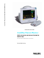
IntelliVue Patient Monitor
MP 2 / 5/ 20 /3 0 / 4 0/ 5 0 / 6 0 / 70 / 8 0 / 9 0
MP 5T /X 2
For monitor release G.0 with software revision G.0x.xx
P a t i e nt M o n i t o r i n g
Philips Medizin Systeme Boeblingen GmbH
Hewlett-Packard Str. 2
71034 Boeblingen
Germany
© Copyright 2002-2008
Koninklijke Philips Electronics N.V.
All Rights Reserved
Part Number M8000-9306M
Reorder Number: 4535 641 12621
Printed in Germany 10/08
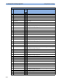
Table Of Contents
1
1 Understanding Configuration
Who is this Guide for?
Which Monitor Models is this Guide for?
What is Configuration Mode?
Who Can Change the Monitor Configuration?
Understanding Profiles and Settings
Entering and Leaving Configuration Mode
About the IntelliVue Support Tool
2 Configuring Profiles and Settings Blocks
Getting Started
Modifying an Existing Profile
Modifying an Existing Settings Block
Creating New Profiles
Deleting a Settings Block or Profile
Renaming a Settings Block or Profile
Changing the Monitor’s Default Profile
Unlocking a Settings Block or Profile
Configuring a Second / Third Main Display
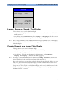
3 Configuring Screens
Understanding Screen Settings
Modifying an Existing Screen
Creating New Screens
Configuring Screens on an XDS Remote Display
Changing the Content of Screen Elements
Changing the Size and Position of Screen Elements
Configuring SmartKeys
Configuring Special Screen Settings
4 Configuration Settings Appendix
About Configuration Settings
Profile Settings
Measurement Settings
Monitor Settings
Unique Monitor Settings
Global Settings
Hardware Settings
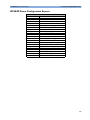
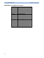
Monitor Database Configuration
H Option-Specific Settings
Release-Specific Information
1
1
1
2
2
3
6
6
9
9
10
11
11
13
13
13
13
14
17
17
18
18
18
19
21
21
22
25
25
28
29
84
118
147
176
184
187
188
1
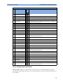
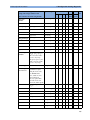
5 Screen & Profile Overview
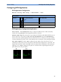
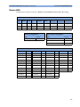
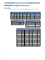
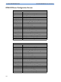
About the Screen Configurations
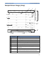
Sample Screen Image (.bmp)
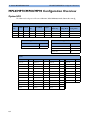
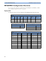
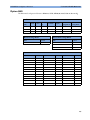
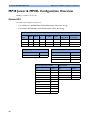
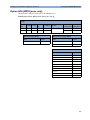
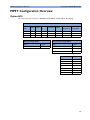
MP60/MP70/MP80/MP90 Configuration Overview
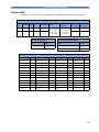
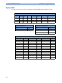
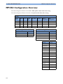
MP40/MP50 Configuration Overview
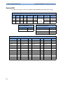
MP20/MP30 Configuration Overview
MP20 Junior & MP20L Configuration Overview
MP5 Configuration Overview
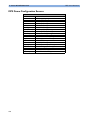
MP5T Configuration Overview
MP2/X2 Configuration Overview
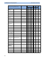
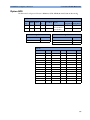
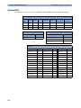
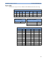
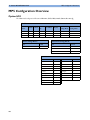
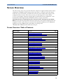
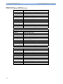
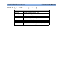
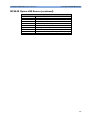
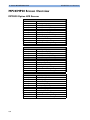
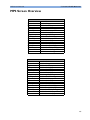
Screen Overview
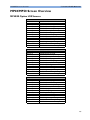
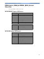
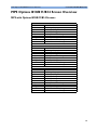
MP60/MP70/MP80/MP90 Screen Overview
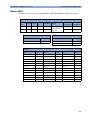
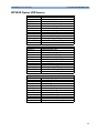
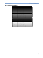
MP40/MP50 Screen Overview
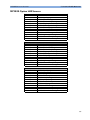
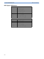
MP20/MP30 Screen Overview
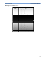
MP20 Junior (M20) & MP20L (M21) Screen Overview
MP5 Screen Overview
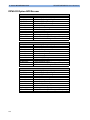
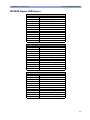
MP5 Options B10/B11/B14 Screen Overview
MP5T Screen Overview
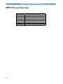
MP2 Screen Overview
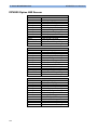
X2 Screen Overview
2
191
191
193
194
198
202
206
208
213
214
215
216
225
230
235
236
241
242
243
244
1
Understanding Configuration
1
Who is this Guide for?
This book is for anyone making permanent changes to the configuration of an IntelliVue Patient
Monitor. You must understand English, be familiar with the monitor and its Instructions for Use,
know how to make changes to measurements and settings in monitoring mode, and understand the
clinical implications of any changes you make.
WARNING
Before starting monitoring, check that the configuration meets your requirements, especially patient
category, alarm limits and paced setting.
WARNING
Changing the configuration may alter the way the monitor performs when monitoring patients. Do
not change anything unless you are aware of the possible consequences, especially if you are monitoring
a patient whilst in configuration mode.
Which Monitor Models is this Guide for?
The descriptions and configuration settings in this configuration guide are valid for IntelliVue Patient
Monitors MP2, MP5, MP20/30, MP40/50, MP60/70, MP80/90, and the IntelliVue X2 MultiMeasurement Module (when used as a standalone monitor), release G.0 with software G.0x.xx. This
guide can not be used for other monitor models or IntelliVue monitors with other software releases.
Not all information contained in this guide applies to all monitor models. If a certain section applies
only to certain models, this is indicated next to the section heading.
For example, if a certain section does not apply to the MP2 and X2, or - in other words - only applies
to monitor models MP5, MP20/30, MP40/50, MP60/70, and MP80/90, it would be indicated like
this:
MP5-90
only
<Section Heading>
1
1 Understanding Configuration
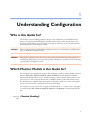
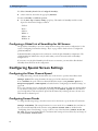
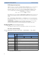
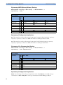
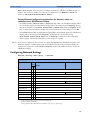
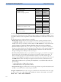
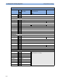
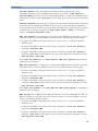
What is Configuration Mode?
What is Configuration Mode?
The monitor ships with preset configurations that are suitable for common monitoring situations. To
develop and store your own configurations you must switch to the monitors configuration mode.
Configuration mode is a password-protected operating mode that lets expert users make permanent
changes to the monitor configuration. It is an extension of monitoring mode; it contains all of the settings
available in monitoring mode plus some settings that are accessible only in configuration mode.
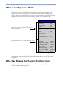
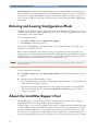
Setup SpO2
For example, when you access the Setup SpO2 menu in
monitoring mode, you will only be able to see and
change these settings.
High Limit
:
100
Low Limit
:
90
Desat Limit
:
80
Alarms
:
On
SpO2
:
On
:
SpO2
QRS Volume
:
1
Tone Modulation
:
Yes
Tone Mod. Type
:
Enhanced
Perfusion
:
On
Average
Pulse (Sp02)
Label
Set Perf Ref.
In configuration mode, these additional settings become
visible.
:
10 sec
High Alarm Delay :
10 sec
Low Alarm Delay
:
10 sec
Desat Delay
:
20 sec
NBP Alarm Suppr. :
On
Extd. Auto OnOff :
Disabled
Color
Cyan
:
In monitoring mode, you can change settings, but cannot permanently store the changes to the monitor
configuration.In configuration mode, you can change and permanently store settings to the monitor
configuration.
Who Can Change the Monitor Configuration?
Only people authorized to do so by their institution should make changes in configuration mode. They
require the configuration mode password.
2
Understanding Profiles and Settings
1 Understanding Configuration
Understanding Profiles and Settings
The IntelliVue patient monitor is highly configurable. To manage its various settings, settings are grouped
into six main categories:
• Profiles
• Screens
• Monitor settings
• Measurement settings
• Global settings
• Hardware settings
All settings except hardware settings can be changed in configuration mode. Hardware settings can be
changed in service mode only (with some exceptions).
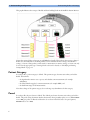
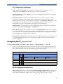
Profiles
Profiles are named combinations of the following “building blocks”:
• Patient category
Profiles
• Paced status
• (Display) Screen
Profile
:
Profile Adult
• Measurement Settings block
Patient Category
:
Adult
• Monitor Settings block.
Paced
:
Yes
Display
: 6 Waves A
A monitor can have up to 20 different Profiles.
When you load a Profile, the configured combination
Measmnt. Settings : Measmt. Adult
of building blocks becomes active.
Monitor Settings : Monitor A
This provides a powerful method to easily adapt the
monitor to specific clinical scenarios or users, or
switch back and forth between different configurations depending on specific phases within a case.
Consider this example: You are in the ER. Your monitor is configured for an adult patient. Your next
patient is a 5-year old child. By switching to a predefined pediatric ER Profile, you can have appropriate
measurement settings (such as alarm limits), patient category and so forth very easily, instead of having to
alter measurements and limits individually. In this example, your monitor’s Profiles can be based on the
age and condition of your patient, but there are of course other use models.
3
1 Understanding Configuration
Understanding Profiles and Settings
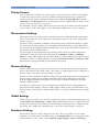
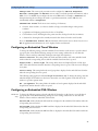
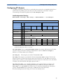
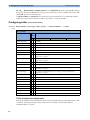
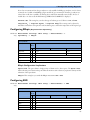
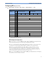
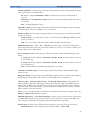
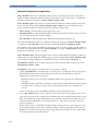
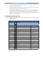
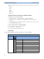
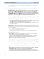
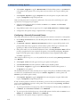
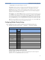
This graphic illustrates the concept of Profiles and their building blocks in the IntelliVue Patient Monitor.
Notice that settings blocks and screens are only linked to a Profile. This indicates that storing a changed
Profile saves the combination of building blocks, but not individual monitor settings, measurement
settings, or Screens. Changes that you have made to measurement or monitor settings, or screens can only
be stored in the appropriate type of settings block or Screen. For details, see "Modifying an Existing
Settings Block" on page 11.
Patient Category
For each profile, a patient category is defined. This patient category becomes active when you load the
Profile. It determines
– the algorithm the monitor uses to process and calculate some measurements (for example
arrhythmia),
– the safety limits that apply for some measurements (for example NBP), and
– the alarm limit ranges for all measurements.
Note that a change of the patient category does not change any alarm limits to fit this category.
Paced
For each profile, the paced status is defined. The defined paced status becomes active when you load the
Profile. The paced setting determines whether the monitor shows pacemaker pulses or not. When Paced
is set to No, pace pulses are filtered and therefore do not show in the ECG wave. For paced patients,
Paced must be set to Yes.
4
Understanding Profiles and Settings
1 Understanding Configuration
Display Screens
A Screen defines the overall selection, size and position of measurement waves, numerics and SmartKeys
on the monitor display. A monitor can have a maximum of 20 preconfigured Screens, optimized for
common monitoring scenarios. Examples of different Screens include the Big Numerics, the 12lead ECG, and the Horizon Screen. For a complete list of Screens supplied with your monitor model,
see the section "Screen Overview" on page 215.
For each Profile, a Screen is defined. This Screen becomes the active Screen when you load the Profile. If
you are using two or three main displays, for each main display a different Screen can be configured.
Measurement Settings
Measurement settings are settings specific to each measurement, for example alarm limits, measurement
color, or measurement unit. For a complete list of measurement settings, see the section "Measurement
Settings" on page 29.
A monitor can have a maximum of 10 blocks of measurement settings. Each block includes the complete
list of measurement settings available. You can configure individual measurement settings differently for
each settings block. By configuring different settings blocks, you can provide customized combinations of
measurement settings for different profiles.
A typical example are the measurement settings blocks provided in the factory default configurations
(documented in this guide). The measurement settings blocks Measmt. Adult, and Measmt.
Pedi, for example, differ mainly by the alarm limits which are configured differently for different patient
ages. When you switch to a different Profile, for example from Profile Adult to Profile Pedi,
the measurement settings block defined for that Profile becomes active.
Monitor Settings
Monitor settings define general aspects of how the monitor works, and include settings that affect more
than one measurement, such as alarm volume, report settings, or display brightness. For a complete list of
monitor settings, see the section "Monitor Settings" on page 84.
A monitor can have a maximum of 10 blocks of monitor settings. Each block includes the complete list of
monitor settings available. You can configure individual monitor settings differently for each settings
block. By configuring different settings blocks, you can provide customized combinations of monitor
settings for different profiles.
For example, you could generate a monitor settings block, in which the monitor’s display brightness is
lowered and the alarm volume is softened, and call it “Night”. When you then assign this block to a new
Profile and name it accordingly, for example “Profile Night”, you can easily switch between day and night
settings.
Global Settings
Global settings are typically set once at monitor installation by service personnel and include settings such
as Altitude, Line Frequency, or Label Set. Global settings are not part of a Profile. They can
be changed in configuration mode only and are automatically stored in the monitor’s configuration with
each change. For a complete list of Global Settings, see the section "Global Settings" on page 147.
Hardware Settings
Most hardware settings can only be changed in service mode. They are typically set once at monitor
installation by service personnel, and include settings, such as Keyboard layout, the configuration of the
monitor interfaces, or video settings, such as Display Type, Display Size, and Display
5
1 Understanding Configuration
Entering and Leaving Configuration Mode
Resolution. Like global settings, hardware settings are independent of Profiles, and any changes you
make to the hardware settings configuration are automatically stored, there is no need to save them in an
extra step. For a complete list of Hardware Settings, see the section "Hardware Settings" on page 176, or
refer to the Service Guide of your monitor model, provided on the Documentation DVD supplied with
your monitor.
Entering and Leaving Configuration Mode
Switching between monitoring and configuration mode does not affect the active settings. You can even
continue to monitor patients while in configuration mode. The password for configuration mode is given
in the monitor’s service documentation.
To enter configuration mode:
1
In the Main Setup menu, select Operating Modes.
2
Select Config and enter the password.
The monitor displays Config at the right hand side of the status line and in the center of the Screen
while you are in configuration mode.
Before you leave configuration mode, always be sure to store any changes you made. You must store
changes made to each Settings Block and to each Profile, individually. As it may be difficult to remember
whether the settings you changed belong to a Monitor Settings block or a Measurement Settings block, we
recommend that you store each block before you leave configuration mode.
WARNING
If you are handing over the monitor to the end-users directly after configuration, make sure that it is in
Monitoring mode.
To leave configuration mode either:
♦
In the Main Setup menu, select Operating Modes and then select the operating mode you
require or
♦
Switch the monitor off, then switch it on again.
– If you switch the monitor off and then on again after less than one minute, it returns in monitoring
mode with the same settings (“hotstart”).
– If you leave the monitor switched off for more than one minute, the Profiles and settings loaded
when you switch back on are determined by the Automat. Default setting. See “Global
Settings” on page 147.
About the IntelliVue Support Tool
The IntelliVue Support Tool is a PC-based software application that is designed to help configuring
IntelliVue monitors and to manage IntelliVue Monitor configurations.
Using the Support Tool, you can, for example, read in (clone) a configuration from an IntelliVue monitor
to a PC, modify this configuration offline on the PC, and then store (clone) the changed version back to
the monitor. With the Support Tool you can clone configurations to more than one monitor at a time.
You can also use the Support Tool to make backups of your configurations, or generate configuration
reports. The configuration files generated by the Support Tool are stored in a format that can be e-mailed.
6
About the IntelliVue Support Tool
1 Understanding Configuration
What Can I Configure with the Support Tool?
You can configure everything you can configure on the monitor, except that you cannot change individual
monitor and measurement settings.
In addition to the configuration on the monitor, the Support Tool allows, for example:
• Changing the order of items in the lists of Screens, measurement or monitor settings blocks.
• Unlocking Profiles, Screens and settings blocks.
• Making realtime waves, or screen trends overlap on the Screen.
• Importing Screens into a configuration, and copying Screens between configurations.
• Importing SmartKey configurations into a configuration.
• Copying monitor settings, measurement settings, and global settings between config files.
• Importing, creating and modifying drug calculator configurations.
For a complete description of the Support Tool functionality, refer to the Support Tool Instructions for
Use, provided with the Support Tool.
How Can I Get a Support Tool License Key?
To use the Support Tool, you must have a license key. To get a license key, you must complete a special
training. Please contact your local Philips Customer Response Center for further details.
The Support Tool functionality your license key permits you to use, depends on your function (e.g.
Biomed / CE / Configuration Expert) and your level of training.
License keys are issued to individuals and they may not be shared. The Support Tool tracks the use of each
license key: you will be held responsible for any configuration changes made using your license key.
7
1 Understanding Configuration
8
About the IntelliVue Support Tool
2
Configuring Profiles and
Settings Blocks
2
Getting Started
To start configuring your monitor, access Profiles by selecting either:
• the Profiles screen element from the monitor’s Info Line, or
• the Profiles SmartKey
, or
• Profiles from the Main Setup menu.
The configuration pop-up keys will appear to let you carry out configuration tasks.
Using the Configuration Pop-up Keys
In configuration mode, the pop-up keys allow you to:
activate a Profile or settings
block
create a new Profile or
settings block based on the
current one
save active settings into the selected
settings block, or settings blocks
into the selected Profile.
delete the selected
Profile or settings block
rename the selected
Profile or settings block
make the current Profile
the default Profile
Select the Confirm pop-up key to apply your changes.
9
2 Configuring Profiles and Settings Blocks
Modifying an Existing Profile
Modifying an Existing Profile
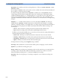
You can change the settings within an existing Profile. The monitor remembers any changes made when
you switch between monitoring mode and configuration mode. All changes can be permanently stored in
configuration mode, as described in the following sections.
Be aware that if you don’t store changes they will be reset to the monitor’s stored configuration when you
• change from configuration or monitoring mode to service or demonstration mode,
• load Profiles or Settings Blocks, or
• switch off the monitor for more than one minute (if the Global Setting Automat. Default is set
to Yes).
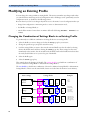
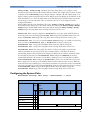
Changing the Combination of Settings Blocks in an Existing Profile
To permanently save a different combination of settings blocks into an existing Profile:
1
Select the Profile you want to change and select the Load pop-up key to activate it.
2
Change the patient category and paced status if necessary.
3
Load the settings blocks you want to have into the activated Profile one after the other by selecting
them in the Profiles menu and then selecting the Load pop-up key. These settings become active
immediately in the monitor, but the asterisk beside the Profile name in the Profiles menu shows that
the newly loaded blocks are not yet stored as part of the Profile.
4
Select the Profile again.
5
Select the Store pop-up key.
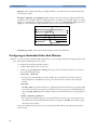
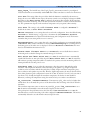
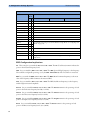
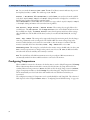
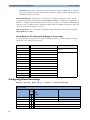
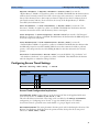
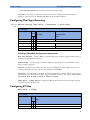
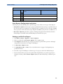
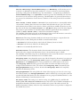
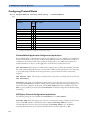
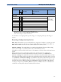
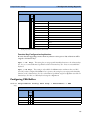
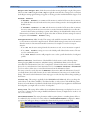
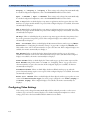
This example shows the changing of a Profile. The existing Profile 1 was built from a combination of
Screen A + Monitor Settings Block A + Measurement Settings Block A.
The new Profile 2 is built from a combination of Screen B + Monitor Settings Block D + Measurement
Settings Block C. This is now the active Profile, because it is loaded into the monitor’s active memory.
Active settings
Display
screens
Settings blocks
screens
layout
content
load
A
Monitor
settings
load
Measurement
settings
load
A
A
B
B
B
Existing Profile 1
10
Examples
C
C
C
D
D
D
New Profile 2
E
E
alarm volume
alarms latching
alarm off time
QRS volume
Network setting
E
ECG alarm limits
ABP alarms on/off
NBP repeat time
Resp trigger mode
Modifying an Existing Settings Block
2 Configuring Profiles and Settings Blocks
Modifying an Existing Settings Block
To change settings in an existing settings block:
1
Select the settings block you want to change and select the Load pop-up key to activate it.
2
Make the changes to the individual measurements or monitor settings.
3
Select the Store pop-up key to overwrite the existing settings. Changes to a settings block affect all
Profiles in which this block is used.
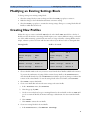
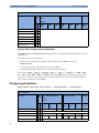
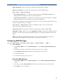
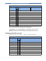
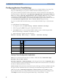
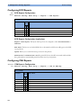
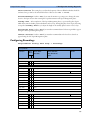
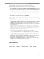
Creating New Profiles
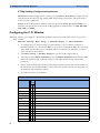
Follow these steps to create a new Profile ICU B based on the Profile ICU A and add it to the list of
Profiles stored in the monitor. As creating a Profile requires you to activate different settings, you should
not do this while monitoring a patient. Each new name you assign to Profiles or Settings Blocks must be
unique, otherwise you have two items with the same name and you will not be able to distinguish them.
Existing Profile:
Profile to be created:
Profiles
Profiles
Profile
:
ICU A
Profile
:
ICU B
Patient Category
:
Adult
Patient Category
:
Pedi
Paced
:
No
Paced
:
No
Display
:
6 Waves A
Display
:
6 Waves B
Measmnt. Settings :
Measmt. A
Measmnt. Settings :
Measmt. B
Monitor Settings
Monitor A
Monitor Settings
Monitor B
:
:
1
Choose a Profile similar to the one you want to create from the list of Profiles available in the monitor.
To preview the combination of settings blocks contained in any Profile, in the Profiles menu,
select that Profile from the list. The Profiles menu (which is grayed-out) changes to indicate the
contents of the selected Profile. To view the settings blocks of the active Profile, select Current.
2
Select Load to activate this Profile.
3
Create a new Profile that references the same settings as the active Profile:
a. In the Profiles menu, select Profile.
b. Select the pop-up key New.
c. Use the on-screen keyboard to type a meaningful name for the new Profile, in this case ICU B. If
you do not name the Profile, the monitor will assign a default name. You can rename the Profile
later.
d. Select Enter.
e. Select Load to activate the new Profile.
4
Create new settings blocks for the new Profile.
a. In the Profiles menu, select Monitor Settings.
11
2 Configuring Profiles and Settings Blocks
Creating New Profiles
b. Select the pop-up key New.
c. Use the on-screen keyboard to type the name of the new settings block, in this case Monitor B.
If you do not name the Settings Block, the monitor will assign a default name. You can rename the
Settings Block later.
d. Select Enter. You have now created a new settings block containing the same monitor settings as
the block Monitor A.
e. Repeat this procedure to create a new measurement settings block.
You have now prepared the structure of the Profile you are creating.
5
Select the required Patient Category for the new Profile. In the Profiles menu, select either
Adult, Pedi, or Neo, or select As Is to retain the patient category active at the time this Profile is
activated. Note that if you configure Patient Category in the default Profile to As Is, the
monitor starts after a coldstart with Patient Category set to Neo. A coldstart will be caused,
for example, after changing the monitor’s database configuration, see "Monitor Database
Configuration" on page 184.
6
Select the required Paced mode for the new Profile. In the Profiles menu, select Yes for paced
patients, No for non-paced patients, or As Is to retain the paced status active at the time this Profile
is activated. Note that if you configure Paced in the default Profile to As Is, the monitor starts
after a coldstart with Paced set to Yes. A coldstart will be caused, for example, after changing the
monitor’s database configuration, see "Monitor Database Configuration" on page 184.
7
Select a Screen for the new Profile.
a. In the Profiles menu, select Display
b. Select the Screen you require from the pop-up list of available Screens.
c. Select Load to confirm your choice.
d. If the monitor has more than one main display, repeat these steps for the additional displays.
If you are using an XDS Remote Display as second or third main display, the default Screen for this
display must be configured in the XDS Application software. It cannot be stored as part of the Profile
configuration of the IntelliVue monitor. For more detail, refer to the Installation and Configuration
Guide for the XDS Application.
N O TE
8
Adjust monitor and measurement settings as required.
9
Store the changed settings to the settings blocks. In the Profiles menu, select
Measmnt. Settings, and then select Store and then Confirm to apply your changes.
Repeat this for Monitor Settings. There is no undo function.
10 Store the finished Profile. In the Profiles menu, select Profile and then select Store and
then Confirm to apply your changes. There is no undo function.
CAUTION
12
When changing settings, you are strongly advised to create new settings blocks, rather than storing changes
to the existing ones. Similarly, when changing a Profile, you are strongly advised to create a new Profile,
rather than storing changes to an existing one. Once you store changes to a settings block or Profile, there
is no way to undo these changes, unless you have saved a backup using the Support Tool. Settings blocks
may be used in more than one Profile. If you edit a settings block it will change in the other Profiles in
which it is used.
Deleting a Settings Block or Profile
2 Configuring Profiles and Settings Blocks
Deleting a Settings Block or Profile
You cannot delete a locked settings block, or one that is used in any Profile. You must remove it from the
Profile or delete the Profile first.
1
From the Profiles menu, select the block or Profile you want to delete.
2
Select the Delete pop-up key.
Renaming a Settings Block or Profile
If you rename a settings block that is used in other Profiles, the name changes in the other Profiles too.
1
From the Profiles menu, select the block or Profile you want to rename.
2
Select Rename.
3
Use the on-screen keyboard to type the new name, then select Enter to apply the change.
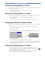
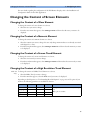
Changing the Monitor’s Default Profile
Every monitor has one default Profile. This is marked with a black diamond.The monitor loads the default
Profile:
• when returning to monitoring mode after leaving demonstration Mode (but not after leaving
configuration or service mode).
• after discharging a patient.
• after being switched off for more than 60 seconds (only if Automat. Default is set to Yes).
To change the default Profile:
1
In the Profiles menu, select the Profile you want to set as default.
2
From the pop-up keys select Set Default. The “default diamond” jumps to this Profile to indicate
that it is now this monitor’s default Profile. This setting takes effect immediately, you do not have to
switch the monitor off and on again.
Unlocking a Settings Block or Profile
Profiles and settings blocks can be locked to prevent them from being modified or deleted. This
ensures that a minimum configuration is always available. A locked Profile or settings block is
identified (in configuration mode only) by a lock symbol.
You cannot unlock Profiles or settings blocks in the monitor’s configuration mode. To lock or
unlock Profiles or settings blocks you need to use the IntelliVue Support Tool.
13
2 Configuring Profiles and Settings Blocks
Configuring a Second / Third Main Display
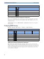
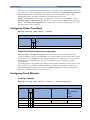
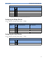
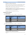
Configuring a Second / Third Main Display
To distinguish between individual main displays, the displays are numbered on the Screen. The number is
shown next to the Screen Name field.
A second main display can be used with
• an MP90 with a Dual CPU, or
• an MP2/X2, MP5, MP60/70, MP80, or MP90 with a single CPU, when using an XDS Remote
Display as the third display.
Display 1 is always the built-in display or the display connected to the first CPU of the Dual CPU
MP90 monitor. Display 2 is the display connected to second CPU of the Dual CPU MP90 monitor
or the XDS Remote Display.
Profiles
Profile
:
ICU B
Patient Category
:
Adult
Paced
:
Yes
Display 1
:
6 Waves B
Display 2
:
12 Lead ECG
Measmnt. Settings :
Measmt. B
Monitor Settings
Monitor B
:
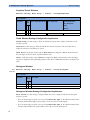
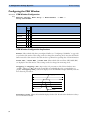
A third main display can be used with
• a D80 Intelligent Display connected to a Dual CPU MP90 monitor, or
• an MP90 with a Dual CPU, when using an XDS Remote Display as the third display.
Display 1 is always the display connected to the first CPU of the MP90 monitor. Display 2 is the
display connected to second CPU, and Display 3 is the display connected to either the D80 or the
XDS Remote Display.
14
Configuring a Second / Third Main Display
2 Configuring Profiles and Settings Blocks
Profiles
Profile
:
ICU B
Patient Category
:
Adult
Paced
:
Yes
Display 1
:
6 Waves B
Display 2
:
12 Lead ECG
Display 3
:
Big Numerics
Measmnt. Settings :
Measmt. B
Monitor Settings
Monitor B
:
Loading a Screen on a Second / Third Display
To load a Screen onto the second or third main display,
• on the second/third display, enter the Change Screen menu and select a Screen from the list of
available Screens, or
• on any display, enter the Profiles menu, select Display 2 (or Display 3) and select a Screen
from the list of available Screens (not possible on the main display of MP2 and X2 monitors).
NO TE
If you are using an IntelliVue monitor with the XDS Remote Display as either the second or third display,
the selection of Screens available for the XDS Remote Display can be different from the Screen selection
for the other displays.
Changing Elements on a Second / Third Display
To change elements on the second or third main display:
NO TE
1
Load the Screen that you want to modify onto the second/third display.
2
Make the required changes to the Screen.
3
Store the Screen. To do this, enter the monitor’s configuration mode, select Profiles ->
Display 2 (or Display 3), then select the Store pop-up key.
Any change to a Screen will mark that Screen modified. In the Change Screen menu, the modified
Screen is shown linked to the original Screen and marked with an asterisk (*).
If you load the same Screen onto more than one display, then modify them differently, and then store one
of the Screens, the modified Screen on the other displays will still be available. The stored Screen will be
available on all displays except on the XDS Remote Display.
Changes made to a Screen viewed on an XDS Remote Display will be stored on the PC connected to the
XDS Remote Display and will not be part of the monitor configuration, see "Configuring Screens on an
XDS Remote Display" on page 18.
15
2 Configuring Profiles and Settings Blocks
16
Configuring a Second / Third Main Display
3
Configuring Screens
3
During monitoring, you can change the content of most of the Screen elements, for example you can
exchange a Resp wave for a Pressure wave. These changes can be permanently stored as part of the
Screen settings in configuration mode.
You can also use the IntelliVue Support Tool to configure Screens offline on a personal computer and
then upload them as part of a configuration file to one or more patient monitors. To use the IntelliVue
Support Tool for Screen configuration, you must have a support tool and a support tool license key
that entitles you to use the Screen configuration functionality. See "About the IntelliVue Support
Tool" on page 6 and the Support Tool Instructions for Use.
Understanding Screen Settings
Screen settings are stored in the Screen. Changing a Screen setting modifies the Screen. This is
indicated by an asterisk (*) in front of the Screen name. In the Change Screen menu, modified Screens
are shown linked to their parent Screens.
Screen settings include:
• the basic layout of a Screen, i.e. the selection, size, and position of any Screen element visible on the
Screen. The Screen layout cannot be modified in the monitor’s configuration mode.
• the content of each Screen element, i.e. the information displayed in each Screen element.
• the selection and sequence of SmartKeys available on a Screen.
• special settings that determine the behavior of certain Screen elements, such as Screen trends,
realtime waves, embedded trend windows, or embedded Other Bed Overview windows.
17
3 Configuring Screens
Modifying an Existing Screen
Modifying an Existing Screen
To change an existing Screen:
N O TE
1
Load the Screen and make the changes to the Screen.
2
In configuration mode, select Profiles -> Display (or Display 2, or Display 3).
3
In the list of Screens, the modified Screen is shown linked to the original Screen and marked with an
asterisk (*). Select the Store pop-up key to overwrite the existing Screen. Changes to the Screen
affect all Profiles in which this Screen is used.
Changes made to a Screen viewed on an XDS Remote Display will be stored on the PC connected to the
XDS Remote Display and will not be part of the monitor configuration, see "Configuring Screens on an
XDS Remote Display" on page 18.
Creating New Screens
1
Load a Screen similar to the one you want to create from the list of Screens available in the monitor.
2
Create a new Screen based on the active Screen:
a. In the Profiles menu, select Display (or Display 2, or Display 3).
b. Select the pop-up key New.
c. Use the on-screen keyboard to type a meaningful name for the new Screen. If you do not name the
Screen, the monitor will assign a default name. You can rename it later.
d. Select Enter.
3
Change the content of the Screen as required.
4
Store the finished Screen:
a. In the Profiles menu, select Display (or Display 2, or Display 3).
b. Select the pop-up key Store and then Confirm to apply your changes. There is no undo
function.
N O TE
Changes made to a Screen viewed on an XDS Remote Display will be stored on the PC connected to the
XDS Remote Display and will not be part of the monitor configuration, see "Configuring Screens on an
XDS Remote Display" on page 18.
Configuring Screens on an XDS Remote Display
For certain IntelliVue monitor models, the XDS Remote Display (IntelliVue XDS solution) can be used as
second or third main display.
When you make changes to a Screen that is viewed on an XDS Remote Display, be aware of the following
implications:
• The changes are stored on the XDS Remote Display and not on the monitor.
• The changed Screen is not part of the monitor configuration and can therefore not be cloned to another
monitor using the IntelliVue Support Tool.
• The changed Screen can be modified with the Screen Editor of the IntelliVue Support Tool.
18
Changing the Content of Screen Elements
3 Configuring Screens
For more details regarding the configuration of the XDS Remote Display, refer to the Installation and
Configuration Guide for the XDS Application.
Changing the Content of Screen Elements
Changing the Content of a Wave Element
To change the content of a wave element on a Screen,
1
Select the wave you want to change.
2
From the wave menu that appears, select Change Wave and then select the wave you want to be
displayed.
Changing the Content of a Numeric Element
To change the content of a numeric element on a Screen,
1
Select the numeric you want to change. You can only change numerics that are not directly associated
with (aligned to) a wave.
2
From the Setup menu that appears, select Change Numeric and then select the numeric you want
to be displayed.
Changing the Content of a Screen Trend Element
To change the content of a screen trend element on a Screen,
1
Select the screen trend you want to change.
2
From the trend menu that appears, select Change Trend and then select the screen trend you want
to be displayed.
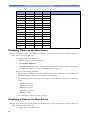
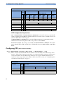
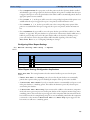
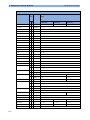
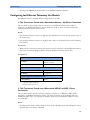
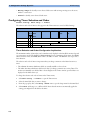
Changing the Content of a High Resolution Trend Element
MP5-90 To change the content of a HiRes Trend element on a Screen,
only 1 Select the HiRes Trend you want to change.
2
From the menu that appears, select the HiRes trend you want to be displayed.
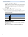
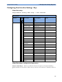
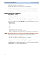
Depending on the H option (see "Understanding H and M Options" on page 27) and C option of your
monitor, the following parameters are available for selection:
H10 / H40
H20
H30
Comments
btbHR
X
X
X
Any SpO2
X
X
X
These 4 parameters are included in the OxyCRG option
(C08)
Resp
X
X
X
MP5: tcpO2 not available.
tcpO2
X
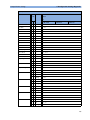
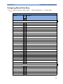
19
3 Configuring Screens
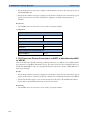
Changing the Content of Screen Elements
H10 / H40
H20
H30
Pulse
X
X
X
Any Perf
X
X
X
tcpCO2
X
X
CO2
X
X
X
ABP
X
X
X
PAP
X
CVP
X
X
X
ICP
X
X
X
CPP
X
X
X
BIS
X
X
X
CCO
X
X
X
AWP
X
X
X
MP20 -90 monitors only
X
Any Agent
X
Delta SpO2
inO2
Comments
X
X
X
Displaying Timers on the Main Screen
MP5-90
only
If you want to have a timer displayed on the Main Screen, you can substitute it for a numeric which is not
directly associated with a wave.
To display a timer on the Main Screen,
1
Select the numeric you want to substitute.
2
Select Change Numeric.
3
Select Any Timer. The monitor automatically uses the timer label with the highest priority that is
not displayed on the Screen yet. See "Configuring Timers" on page 139.
Be aware of the following restrictions:
• If limited space is available, some elements displayed in the Timers window may not be displayed. The
minimum information displayed is the elapsed or remaining time.
• The maximum number of timers that can be displayed on the Main Screen depends on your monitor
model:
– MP60-90: four timers
– MP40-50: three timers
– MP20-30: two timers
– MP5/MP5T: one timer
– MP2/X2: no timer
• Any timer label can only be used once per Screen.
Displaying a Clock on the Main Screen
MP5-90
only
If you want to have a clock displayed on the Main Screen, you can substitute it for a numeric which is not
directly associated with a wave.
To display a clock on the Main Screen,
20
Changing the Size and Position of Screen Elements
1
Select the numeric you want to substitute.
2
Select Change Numeric.
3
Select Clock.
3 Configuring Screens
Be aware of the following restrictions:
• Only one clock can be displayed per Screen
• If limited space is available, the label “Clock” may not be displayed. The minimum information
displayed is the time.
Displaying a ProtocolWatch Status Indicator on the Main Screen
MP5-90 If you want to have a ProtocolWatch status indicator displayed on the Main Screen, you can substitute it
only for a numeric which is not directly associated with a wave.
To display a ProtocolWatch status indicator on the Main Screen,
1
Select the numeric you want to substitute.
2
Select Change Numeric.
3
Select PW Status.
Only one ProtocolWatch status indicator can be displayed per Screen.
Changing the Size and Position of Screen Elements
You cannot change the size and position of Screen elements. This is a configuration service that is
provided, at a charge, by Philips, for monitors with option C20.
Configuring SmartKeys
There are two ways to configure SmartKeys:
• Configuring a different list of SmartKeys for each Screen (not possible for MP2/X2)
• Configuring a global list of SmartKeys that applies for all Screens
Configuring a Different List of SmartKeys for Each Screen
MP5-90 The selection and order of SmartKeys that are specific to a Screen are stored as part of the Screen, i.e. as a
only Screen setting. This can be configured on the monitor (in configuration mode) or by using the Support
Tool Screen Editor. The following describes how to configure SmartKeys on the monitor. For a detailed
description on how to use the Support Tool Screen Editor, see the Support Tool Instructions for Use.
To change the selection of SmartKeys displayed,
1
Select Main Screen, then select the left double arrow key to scroll back one page of SmartKeys.
2
Select the SmartKey SmartKeys to open a menu that lists all SmartKeys currently configured for
that Screen. From the pop-up key line, select Add to open a second menu that contains all available
SmartKeys.
3
From the second menu, select the desired SmartKey. This adds the new key to the bottom of the list of
configured SmartKeys (on the left). The maximum number of SmartKeys per Screen is 30 for the
MP60/70/80/90, and 24 for the MP40/50, MP20/30, and MP5.
21
3 Configuring Screens
Configuring Special Screen Settings
To delete a SmartKey from the list of configured SmartKeys,
♦
select it in the list, then select the pop-up key Delete.
To move a SmartKey to a different position,
♦
Use the Sort Up and Sort Down pop-up keys. The number of SmartKeys visible at a time
depends on the monitor’s display resolution:
SVGA: 6
XGA: 7
SXGA: 9
WXGA: 9
WXGA+: 10
WSXGA: 11
Configuring a Global List of SmartKeys for All Screens
The global list of SmartKeys is stored as a unique monitor setting in the monitor configuration. See the
section "Configuring User Interface Settings - Keys" on page 143 for details on how to configure the
global SmartKey list.
Individual SmartKey configurations for each Screen override the global SmartKey configuration. The
global SmartKey list will therefore only be visible when you load a Screen that has no SmartKeys
configured to it.
If you want to use the global SmartKeys for all Screens on a monitor, you must delete all individual
SmartKeys from all Screens in the configuration.
Configuring Special Screen Settings
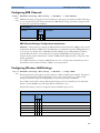
Configuring the Wave Channel Speed
To change this setting, select the measurement wave on the Screen to open the related Wave menu.
Change Speed This setting determines the wave speed of the related wave channel.
If set to Global, the speed of the wave channel follows the monitor setting Global Speed (or
RespiratorySpeed, or EEG Speed) as described under "Configuring User Interface Settings" on
page 110.
If set to any of the fixed speeds (6.25, 12.5, 25, 50 mm/sec), the speed of that wave channel follows
its own distinct setting and is not affected by any changes of the Global Speed. The wave channel
speed is independent of the wave (label) depicted in the channel. If you change the wave, the new wave
will retain the set channel speed.
Configuring Screen Trends
To change the following settings, select the screen trend on the Screen to open the related Trend menu.
Change TrendTime This setting determines in a screen trend. If set to Global, the trend time in
the screen trend channel follows the monitor setting Screen Trend Time as described under
"Configuring Screen Trend Settings" on page 91. If set to any of the fixed times (30min, 1h, 2h, 4h,
8h, 12h), the screen trend time follows its own distinct time setting and is not affected by any changes of
the global Screen Trend Time.
22
Configuring Special Screen Settings
3 Configuring Screens
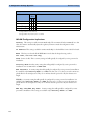
Change View The screen trend presentation can be configured to Tabular, Graphical,
Horizon, or Histogram. The Tabular view can only be used with aperiodic measurements, such as
NBP, C.O., C.I., PAWP. If you configure the view of an NBP trend, for example, to Tabular, and
during monitoring the user changes the trend to a periodic measurement, such as ABP, the view
automatically switches to Graphical.
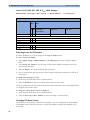
ShowHorizon Trend The horizon view is made up of 4 elements:
1
a horizon, drawn in white, as a reference baseline to help you visualize changes in the patient’s
condition.
2
a graphical trend, displaying patient data for the set TrendTime.
3
a trend indicator arrow, indicating how the patient trend has developed in the last ten minutes.
4
a deviation bar, showing how the currently measured value deviates from the stored baseline.
If you set ShowHorizon Trend to Yes, all 4 elements of the horizon view are shown. If you set it to
No, the graphical trend information (2) is not displayed in the trend channel.
Configuring an Embedded Trend Window
To change the following settings, select the embedded Trend window on the Screen to open the related
pop-up key line. Note that the following settings are Screen settings and therefore do not affect the
behavior of the normal (not embedded) Vital Signs and Graph Trend windows.
Select Interval This setting defines the trend interval that will be used in the embedded trend
window when the corresponding Screen (with the embedded trend window) is opened.
Graph Trend / Vital Signs This setting defines the view (Graphical Trends or Vital Signs
table) of the embedded trend window when the corresponding Screen is opened. The view can be changed
at any time.
Select Group This setting defines the trend group that is displayed in the embedded trend window
when the corresponding Screen is opened.
The following setting applies for embedded Graph Trend windows only. To change the setting, select the
embedded Graph Trend window on the Screen, then select one of the segments on the left side of the
window to open the segment menu.
No. of Segments This setting defines the number of trend segments displayed in the embedded
Graph Trends window when the Screen is opened.
Configuring an Embedded CSA Window
MP40-90 To change the following settings, select the embedded CSA window on the Screen to open the related
only pop-up key line. Note that the following settings are Screen settings and therefore do not affect the
behavior of the normal (not embedded) CSA window.
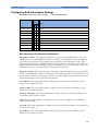
On/Off SEF defines whether the SEF trend line is displayed in the embedded CSA window when the
corresponding Screen is loaded.
On/Off MDF defines whether the MDF trend line is displayed in the embedded CSA window when the
corresponding Screen is loaded.
On/Off PPF defines whether the PPF trend line is displayed in the embedded CSA window when the
corresponding Screen is loaded.
23
3 Configuring Screens
Configuring Special Screen Settings
Buffer defines which of the three preconfigured buffers is used when the Screen with the embedded
CSA window is loaded.
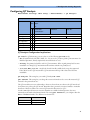
On/Off Clipping Set Clipping to On to improve the 3-D presentation of the embedded CSA
and make it more “readable”. When set to On, peaks in the spectral lines are artificially clipped at a certain
height (see "CSA Window Configuration Implications" on page 98). If Clipping is Off, peaks can be
displayed over the full window height which may result in a more cluttered presentation.
Clipping
Hidden lines
Frequency Scale defines the bandwidth displayed in the embedded CSA.
Configuring an Embedded Other Bed Window
MP5-90
only
For Screens with an embedded Other Bed window, you can configure which bed is displayed in the Other
Bed window each time the Screen is loaded.
To configure the embedded Other Bed window,
1
2
select the Other Bed window on the Screen
select the pop-up key My Care Group. This opens the Care Group menu where you can choose
between the following settings:
– Bed <xx> (Bed ID)
If you select a specific Bed ID, the monitor displays the associated bed every time the Screen is
loaded. If this bed is unavailable, the message “No data from bed” is shown in the embedded
window.
– Any Bed
Select Any Bed if you want the monitor to display the first bed shown in the care group list. If this
bed is removed from the care group, the new first bed in the care group is automatically displayed.
The setting Any Bed might be unavailable if it has been disabled for this Screen using the Support
Tool.
– Blank (Factory Default)
This is the factory default setting used on the “Other Bed” Screen that is part of the Support Tool
Screen library. If an embedded Other Bed window is configured to Blank, the window is empty
when the Screen is loaded.
At any time during monitoring, the user can select the Other Bed window and temporarily change the
current setting.
24
4
Configuration Settings
Appendix
4
About Configuration Settings
The IntelliVue Patient Monitor is pre-configured with factory default settings when it is shipped. This
section documents the factory default settings and lists the configuration implications that need to be
considered when changing settings from their default.
The configuration implications are only provided in this guide. You must read this document before
you modify monitor configurations.
The settings documented here are valid for IntelliVue Patient Monitors release F.0 with software
F.0x.xx.
Documenting Monitor Configurations
If you change settings from their default, this document will no longer reflect your configuration.
A Philips representative or trained biomedical engineer can generate a detailed report of the changed
monitor configuration using the IntelliVue Support Tool. Make sure you review the description of this
functionality in the Support Tool Instructions for Use before you interpret the content of this report.
Understanding Configuration Implications
When you permanently change any element of the configuration, you must consider the effect of the
new configuration on both patient and application behavior. For additional information on the
context of the configuration settings, see your monitors Instructions for Use. Always ensure that the
monitor users are aware of the configuration settings.
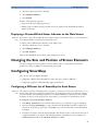
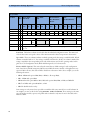
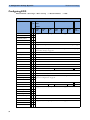
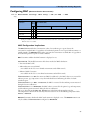
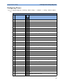
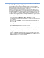
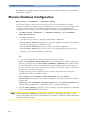
Using the Configuration Tables
The “breadcrumb trail” at the top of each table indicates which Settings Block the settings are grouped
under. For example, “Measurement Setting: Main Setup -> Measurements ->
ECG” means that the ECG settings in the table below the heading are part of the Measurement Settings
Block. This is also the path you should follow to access the settings in the table: in this example, to
configure ECG settings, in the Main Setup menu, select Measurements and then select ECG.
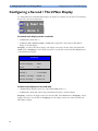
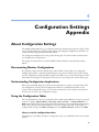
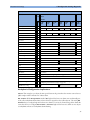
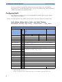
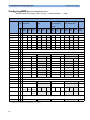
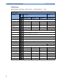
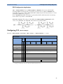
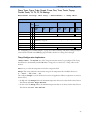
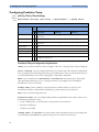
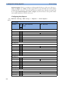
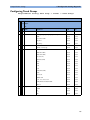
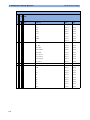
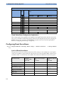
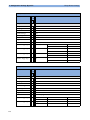
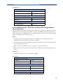
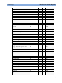
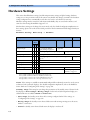
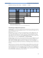
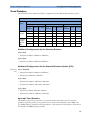
How to read the configuration tables
The following is a (modified) example of a configuration table, as you will find it in the sections of this
manual.
25
4 Configuration Settings Appendix
About Configuration Settings
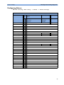
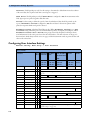
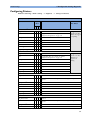
Factory Defaults
Item Name
Oper. MP20 - MP90
Mode (H10/20/40)
MP5 - MP90
(H30)
MP20 (M20/M21)
MP5T
MP5 (H10/20/40)
MP5 (B10/B11/B14)
MP2/X2
MP2/X2
C M Profile Profile Profile Profile Profile Profile Profile Profile Profile Profile Profile Profile Profile
Adult Pedi
Neo
Adult Pedi
Neo
Adult Pedi
Neo
Adult Pedi
Neo
Outdoor
Alarms from
x
x Sys.
Sys. High
x
x 160
120
90
180
160
70
40
70
90
Sys. Low
x
x 90
Alarms
x
x On
3 min
10 min
10 min
15 min
Manual
Auto
Repetition Time x
x 15 min
Mode
x
x Auto
Done Tone
x
Off
NBP Time
x
not applicable, this setting is stored in the Monitor Settings Block: see "Configuring User Interface Settings" on
page 110.
Manual
On
Off
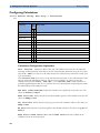
Item Name The leftmost column in each table lists the individual configuration items. The names and
order of these items correspond to those of the menu items in the related setup menu in the monitor.
Oper. Mode These two columns indicate in which operating mode the setting is available/visible. If both
columns are marked with an “x”, the setting is available in both modes. If only one column is marked, the
setting is available in the corresponding mode only. Abbreviations used for the operating modes in this
guide are: C for Configuration mode, M for Monitoring mode, S for Service mode.
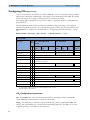
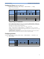
Monitor Models (Options) This section lists the actual factory default settings for each configuration
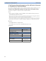
item. Some factory default settings may differ between different monitor models or H (application area)
options. If this is the case, this section will be divided into subsections. In the above example, you see the
following subsections:
• MP20 - MP90 with options H10, H20, or H40 (i.e. all except H30),
• MP5 - MP90 with option H30
• MP20 with model option M20 or M21, MP5 with options H10, H20, or H40, and MP2/X2
• MP5T and MP5 with options B10, B11, or B14
• MP2/X2 (Profile Outdoor only)
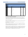
Some settings are only entered once per table row with the table entry extended to cover all columns. In
our example, you can see this for the settings Alarms from and Alarms. These settings are the same
across all monitor models, options, and profiles and are therefore only entered once in the table, in the
leftmost column.
26
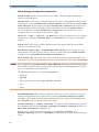
About Configuration Settings
4 Configuration Settings Appendix
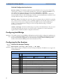
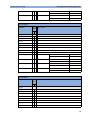
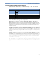
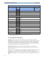
Profile Adult / Profile Pedi / Profile Neo / Profile Outdoor All IntelliVue monitor models are shipped
with different profiles to accommodate different monitoring environments and patient categories.
Therefore, the default values for some settings differ between different profiles. In the example table above,
you can see this for the settings Sys. High, Sys Low, and Auto/Manual for which the subsections
are divided into different columns representing the different profiles. The column headings correspond to
the names of the profiles in the monitor, for example Profile Adult, or Profile Outdoor.
To keep the tables as readable as possible, the following rules apply:
– If the same default value applies to more than one profile in the same subsection, the table entry will
be extended to cover all profiles that apply, and the value will be listed in the leftmost column only
(see Repetition Time or Auto/Manual).
– If the same default value applies to the same profile in different subsections, it is only listed in the
leftmost subsection. For example, the default for Sys. High in Profile Pedi in MP5
through MP90 monitors with option H30 (second subsection from the left) is the same as it is in
Profile Pedi in MP20 through MP90 monitors with options H10/20/40 (leftmost
subsection). It is therefore only listed in the leftmost subsection and the corresponding table entry in
the column Profile Pedi for MP20 through MP90 monitors with option H30 is left empty.
not applicable Whenever you see a statement in the settings tables starting with “not applicable” (as in
NBP Time), this can mean two things (the exact reason will always be given in the context):
• the setting appears as a menu item in the related Setup menu, but is actually stored in a different
context. For example, the NBP Time setting appears in the Setup NBP menu. However, it is not
stored as an NBP measurement setting, but as a monitor setting in the User Interface menu.
• the setting appears as a menu item in the related Setup menu, but cannot be stored in the monitor
configuration. For example, the setting C.O. in the Cardiac Output Setup menu (see "C.O.
Configuration Implications" on page 56) defines the On/Off status of the C.O. measurement, i.e.
whether the Cardiac Output measurement is switched On or Off. However, the C.O. measurement (as
most other measurements in the IntelliVue monitor) can only be switched On if a C.O. transducer is
connected to the monitor. Therefore this setting cannot be permanently stored in the monitors
configuration.
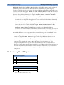
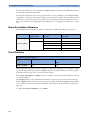
Understanding H and M Options
Application Area Options
H10
General/Intensive Care
H20
Neonatal
H30
Anesthesia
H40
Cardiac Care
MP20 Model Options
M20
1
M21
MP20 Junior
MP20L
1.MP20 option M21 is available in the US only.
27
4 Configuration Settings Appendix
Profile Settings
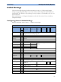
Profile Settings
Profile Settings: Main Setup -> Profiles
Factory default settings for Profiles depend on the monitor model, as well as the monitor’s H and A
option. For detailed information on all factory-provided default Profiles, see the section “Configuration
Overview”, starting on page 194.
The monitor does not need a Profile to start monitoring. If, in the case of an error, no configuration is
loaded, or if a loaded configuration is corrupt, the monitor will be operational and use the factory defaults
documented in the configuration tables of this guide. The Paced status will be set to Yes and the
Patient Category will be set to Neo. An appropriate configuration should then be loaded onto the
monitor using the IntelliVue Support Tool.
The default Profile is used after discharging a patient, leaving demonstration, or when the monitor is
switched off for more than 60 seconds (if the global setting Automat. Default is set to Yes).
28
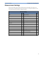
Measurement Settings
4 Configuration Settings Appendix
Measurement Settings
This section lists all the settings grouped in the Measurement Settings Block. They define how the
monitor measures and displays patient data. Read any information on configuration implications at the
end of each section before you make any configuration changes.
Measurement Settings
Page
Page
ECG
30
CO2 (Capnometry)
62
ECG/Pulse Alarms
33
awRR (from Capnometry)
63
System Pulse
35
Resp (Impedance Respiration)
64
Arrhythmia
36
Spirometry
65
ST Analysis
39
RRspir (Respiration from Spirometry)
67
QT Analysis
41
EEG
67
SpO2
42
EEG Montages
69
Delta SpO2
45
BIS
71
NBP
46
Temperature
72
Invasive Pressure
47
Predictive Temperature
74
CPP
53
Delta Temp
75
PPV
54
VueLink
75
C.O.
55
IntelliBridge
76
CCO
56
Gas Analyzer
76
SVR
57
CO2 (from Gas Analyzer)
81
SO2
58
awRR (from Gas Analyzer)
82
Sp-vO2
59
MAC
83
tcGas
60
29
4 Configuration Settings Appendix
Measurement Settings
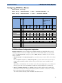
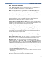
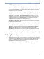
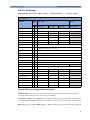
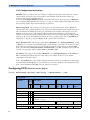
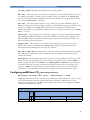
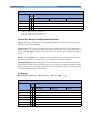
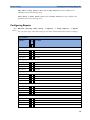
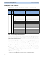
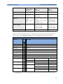
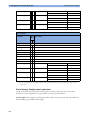
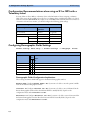
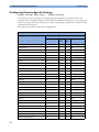
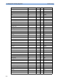
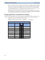
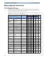
Configuring ECG
Measurement Settings: Main Setup -> Measurements -> ECG
Factory Defaults
Item Name
Oper. MP5 - MP90 (H10/20/40)
Mode
MP5T
MP5 - MP90 (H30)
MP2/X2
MP2/X2
C M Profile
Adult
30
Profile
Pedi
Profile
Neo
Profile
Adult
Profile
Pedi
Profile
Neo
High Limit
x
x not applicable, see "Configuring ECG/Pulse Alarms" on page 33.
Low Limit
x
x
ECG/Arrhy Alarms
x
x
Profile
Outdoor
AlarmSrc (ECG/AR)
x
x
ECG
x
x On
Paced
x
x not applicable, the paced status is stored as in a Profile, see "Profile Settings" on page
28
QRS Volume
x
x not applicable, this setting is stored in the Monitor Settings Block, see "Configuring
User Interface Settings" on page 110
Primary Lead
x
x II
Secondary Lead
x
x V (V1)
Va Lead
x
x V2
Vb Lead
x
x V5
Analysis Mode
x
x Multi Lead
Lead Placement
x
x Standard
Mod.LeadPlacment
x
x Off
Filter
x
x Monitor
SyncPulse Sensit.
x
x Medium (MP2/X2, MP5 only)
SyncPulse Marker
x
x On (MP2/X2, MP5 only)
Auto Filter
x
Fix PacerAmplit
x
Default ECG Size
x
Color
x
Green
x 4.0 sec
Asystole Threshold
x
Δ ExtrTachy
x
Tachy Clamp
x
Δ ExtrBrady
x
Filter
not applicable, these settings are stored in the Monitor Settings Block, see "ECG
Application Configuration" on page 99
White
3.0 sec
not applicable, see "Configuring ECG/Pulse Alarms" on page 33
Brady Clamp
x
ECG Al. OFF Inop
x
Cyan
Fallback
x
On
Alarms Off
x
not applicable, see "Configuring ECG/Pulse Alarms" on page 33
AlarmSource Sel.
x
PulseAlarms Tele
x
Monitor
4.0 sec
Measurement Settings
4 Configuration Settings Appendix
ECG Configuration Implications
ECG This setting lets you switch the ECG measurement On or Off. If ECG is switched Off, the
monitor will change to Pulse as alarm source, if a Pulse is available. One exception to this rule can arise
when you have a telemetry device paired with your monitor. If PulseAlarms Tele (see "Configuring
ECG/Pulse Alarms" on page 33) is configured to Disabled, the monitor does not fall back to the
System Pulse as alarm source.
Primary Lead / Secondary Lead / Analysis Mode The monitor uses the primary and
secondary lead to compute HR and to analyze and detect cardiac arrhythmias. They are also available for
recordings and for display on the Information Center. The Secondary Lead setting is used only if
Analysis Mode is configured to Multi Lead (instead of Single Lead) arrhythmia analysis. It
determines which additional lead will be used for arrhythmia analysis.
Va Lead / Vb Lead If you are using a 6-lead ECG cable, the two chest leads can be positioned at
any two of the V1 to V6 positions. The Va Lead / Vb Lead settings tell the monitor which positions
you have used so that the chest leads will be correctly labeled on the monitor and in printouts. If the
Global setting ECG Cable Color is set to IEC, these settings are labeled Ca Lead and Cb Lead.
Lead Placement Set this setting to EASI if you are using EASI lead placement. This tells the
monitor that you are using EASI lead placement. The label “EASI” will be shown beside the 1mV
calibration bar on the ECG wave on the display, and “EASI” is marked on any recorder strips and
printouts.
Mod.LeadPlacment When Mod.LeadPlacment is set to On, 12 Lead ECG Reports will be
labelled 12 Lead ECG Report (Mason-Likar), and captured 12-lead ECGs will be labelled Mason-Likar to
the right of the bandwidth annotation at the Information Center. When Mod. LeadPlacment is set
to Off, 12 Lead ECG Reports will be labelled 12 Lead ECG Report, and captured 12-lead ECGs will not
be annotated at the Information Center.
Filter The Filter setting defines how ECG waves are smoothed.
• Monitor: The Monitor filter results in an ECG bandwidth of 0.5 - 40 Hz for the Adult, and 0.5 55Hz for the Pedi and Neo patient category. Use under normal measurement conditions.
• Extended Monitoring: This setting is only available for the Pedi and Neo patient category. Using
this filter results in an ECG bandwidth of 0.5 – 150 Hz. Use for pediatric and neonatal patients when
diagnostic quality is required but low frequency interference or a wandering baseline may be expected.
The upper edge frequency is the same as the Diag setting and the lower edge frequency is the same as
the Monitor setting.
• Filter: Using this filter reduces interference to the signal and results in an ECG bandwidth of 0.5 –
20 Hz for all patient categories. It should be used if the signal is distorted by high frequency or low
frequency interference. High frequency interference usually results in large amplitude spikes making the
ECG signal look irregular. Low frequency interference usually leads to a wandering or rough baseline. In
the operating room, the Filter reduces artifacts and interference from electrosurgical units. Under
normal measurement conditions, selecting Filter may suppress the QRS complexes too much and
thus interfere with the clinical evaluation of the ECG displayed on the monitor. This does not affect the
ECG analysis performed by the monitor. If AutoFilter ("ECG Application Configuration" on page
99) is set to On, the filter setting will automatically be set to Filter if electromagnetic interference is
detected.
31
4 Configuration Settings Appendix
Measurement Settings
• Diag (Diagnostic): The setting Diag selects the highest available ECG bandwidth which is 0.05 to
150 Hz for all patient categories. Use when diagnostic quality is required. The unfiltered ECG wave is
displayed so that changes such as R-wave notching or discrete elevation or depression of the ST
segments are visible.
SyncPulse Sensit / SyncPulse Marker These settings are only available in MP2/X2 and
MP5 monitors. In the MP5 it is only available if an MIB/RS232 interface is installed and the driver ECG
Sync Pulse is configured for one of the MIB ports (see the MP5 Service Guide for detailed setup
information). If these requirements are met, the monitor outputs a SyncPulse via the MIB/RS232
interface (MP5) or the ECG Sync Pulse Output Connector (MP2/X2) which can be used to synchronize
external medical devices (such as CT scanners) to the patient’s ECG. Both settings are available in
monitoring mode and configuration mode.
• Set SyncPulse Marker to On to display SyncPulse markers in the ECG wave on the monitor
Screen.
• SyncPulse Sensit lets you change the sensitivity of the Sync Pulse detection. If
SyncPulse Marker is switched On, and not every QRS complex in the ECG wave on the monitor
is marked with a Sync Pulse marker, you should increase the sensitivity (Medium or High) until you
see a marker for each QRS complex. If you see Sync Pulse markers in areas of the ECG wave other than
the QRS complexes, lower the sensitivity (Medium or Low).
Asystole Threshold This setting lets you adjust the time period between the point where the
monitor cannot detect a QRS complex and the indication of an asystole alarm. It also affects the way the
enhanced asystole detection behaves, see "General Global Settings Configuration Implications" on page
148.
Color The color setting defines the color for ECG, Arrhythmia, ST, and QT. The color setting for
Pulse is taken from the system pulse source.
ECG AL. Off Inop If ECG alarms are off or Pulse is selected as active alarm source, the INOP
ECG/ARRH ALARM OFF is shown permanently. If you do not want this INOP to appear, you must set
ECG AL. Off Inop to Off. If you want the ECG/ARRH ALARM OFF INOP to be automatically
escalated to a yellow alarm after a fixed time, configure it to one of the available choices: Yellow @2h,
Yellow @4h, Yellow @6h, or Yellow @8h.
Fallback If Fallback is configured On and there is a LEAD OFF INOP in the primary lead (and in
the secondary lead, if you are using multi-lead monitoring) for longer than 10 seconds, and if another lead
is available, this available lead automatically becomes the primary lead. This is known as lead fallback.
When the Leads Off condition is corrected, the leads are automatically switched back.
32
Measurement Settings
4 Configuration Settings Appendix
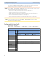
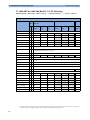
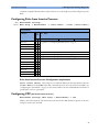
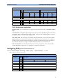
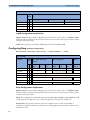
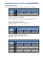
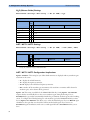
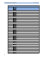
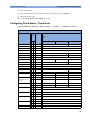
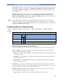
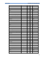
Configuring ECG/Pulse Alarms
Measurement Settings:
Main Setup -> Measurements -> ECG -> AlarmSrc(ECG/AR), or
Main Setup -> Measurements -> Pulse -> AlarmSrc(ECG/AR)
Factory Defaults
Item Name
Oper. MP20 - MP90 (H10/20/ MP5 - MP90 (H30)
Mode 40)
MP20 (M20/M21)
MP2/X2
MP5 (H10/20/40)
MP5T
MP2/X2
C M Profile Profile Profile Profile Profile Profile Profile Profile Profile Profile
Adult Pedi
Neo
Adult Pedi
Neo
Adult Pedi
Neo
Outdoor
Alarms Source
x
x ECG/Arrhythm
ECG/Arrhy Alarms
x
x On
Pulse Alarms
x
x Off
High Limit
x
x 120
160
200
120
Low Limit
x
x 50
75
100
50
Δ ExtrTachy
x
20
Tachy Clamp
x
200
220
240
200
Δ ExtrBrady
x
20
Brady Clamp
x
40
Alarms Off
x
Enabled
AlarmSource Sel.
x
Enabled
PulseAlarms Tele
x
Enabled
Auto
50
40
Auto
60
80
Auto
40
ECG/Pulse Alarms Configuration Implications
Alarms Source In most cases the heart rate and Pulse numerics are identical. In order to avoid
simultaneous alarms on heart rate and Pulse, the monitor uses either ECG or Pulse as its active alarm
source. The Alarm Source setting lets you choose ECG, Pulse or Auto as the source of heartrelated rate alarms.
• ECG/Arrhythm: Select ECG/Arrhythm if you want the heart rate from the ECG to be the alarm
source.
Even with Alarm Source set to ECG/Arrhythm, if you switch the ECG measurement off, the
monitor will automatically use Pulse as alarm source, provided a pulse source is switched on and
available.
Pulse: If you select Pulse as the active alarm source, the monitor will prompt you to confirm your
choice. Be aware that if you select Pulse, all arrhythmia and ECG HR alarms are switched off.
• Auto: If the Alarm Source is set to Auto, the monitor will use the heart rate from the ECG
measurement as alarm source whenever the ECG measurement is switched on and at least one ECG
lead can be measured without an INOP condition.
The monitor will automatically switch to Pulse as the alarm source if:
33
4 Configuration Settings Appendix
Measurement Settings
– a valid ECG lead can no longer be measured
and
– a Pulse source is switched on and available.
The monitor then uses the pulse rate from the measurement currently active as system pulse. While
Pulse is the alarm source, all arrhythmia and ECG HR alarms are switched off. If an ECG lead
becomes available again, the monitor automatically uses ECG/Arrhythm as alarm source.
N O TE
WARNING
If the ECG measurement is switched off, the monitor will always change to Pulse as alarm source, if a
Pulse source is available. One exception to this rule can arise when you have a telemetry device paired with
your monitor. The monitor ECG is then deactivated but the monitor may be configured to allow only
ECG as the active alarm source (see setting AlarmSource Sel.). In this case the monitor will not
switch to Pulse as alarm source and Pulse will not be available as a selection in the ECG/Pulse Alarms
menu.
Selecting Pulse as the active alarm source for HR/Pulse switches off most arrhythmia alarms (see the
Instructions for Use), including Asystole, Vfib and Vtach alarms, and the heart rate alarms. This is
indicated by the crossed-out alarm symbol beside the ECG heart rate numeric and the message
ECG/ARRH ALARM OFF, if configured (see "ECG Configuration Implications" on page 31).
High and low pulse rate and extreme bradycardia and extreme tachycardia alarms from Pulse are active.
ECG/Arrhy Alarms This setting is only available if Alarm Source is set to ECG/Arrhythm or
Auto. Be aware that with Alarm Source set to ECG/Arrhythm, if you switch ECG/Arrhy
Alarms off, all Pulse alarms are switched off as well.
Pulse Alarms This setting is only available if AlarmSource is set to Pulse and a pulse signal is
currently measured. Be aware that with Alarm Source set to Pulse, if you switch Pulse Alarms
off, all ECG and Arrhythmia alarms are switched off as well.
High Limit/Low Limit ECG and Pulse share the same alarm limits. These alarm limits apply to
the currently selected alarm source, either ECG/Arrhythm or Pulse. Note that if you change the High/Low
alarm limits in the ECG/Pulse Alarms menu, this will also change the High/Low alarm limits in the
Setup Pulse menu and Setup ECG menu and vice versa.
Δ ExtrTachy, Δ ExtrBrady Extreme bradycardia and extreme tachycardia alarms are based on the
ECG/Pulse limit alarms. Use the Δ ExtrTachy and Δ ExtrBrady setting to define the difference
between the heart rate limit and the extreme limit. For example, if the heart rate high limit is 120 bpm and
the difference is 20 bpm then the extreme tachycardia limit is 140.
ECG and Pulse share the same alarm limits. The Δ ExtrTachy and Δ ExtrBrady settings apply to the
currently selected alarm source, either ECG or Pulse. If you change the Δ ExtrTachy or Δ ExtrBrady
setting in the ECG/Pulse Alarms menu, this will also change the Δ ExtrTachy or Δ ExtrBrady
setting in the Setup Pulse menu and Setup ECG menu and vice versa.
34
Measurement Settings
4 Configuration Settings Appendix
Tachy Clamp, Brady Clamp The Brady and Tachy clamp allows you to configure a safety
threshold for the extreme bradycardia and tachycardia alarm limits. For example, if the low heart rate limit
is 50 bpm and the Δ ExtrBrady setting is 20 bpm (50 bpm - 20 bpm = 30) with a Brady clamp set at
40, the resulting extreme bradycardia limit would be 40 bpm (instead of 30 bpm). If the clinician sets the
ECG alarm limit above or below the limit clamps for an individual patient, the limit clamps become the
extreme brady or extreme tachy alarm (these are red alarms). Be sure to set the clamps beyond the
configured ECG limits.
ECG and Pulse share the same alarm limits. The Tachy Clamp and Brady Clamp settings apply to
the currently selected alarm source, either ECG or Pulse. If you change the Tachy Clamp or Brady
Clamp setting in the ECG/Pulse Alarms menu, this will also change the Tachy Clamp or Brady
Clamp setting in the Setup Pulse menu and Setup ECG menu and vice versa.
Alarms Off If this setting is configured to Disabled, the user cannot switch off ECG alarms in
monitoring mode. Note that changing the Alarms Off setting in the ECG/Pulse Alarms menu, also
changes the Alarms Off setting in the Setup Pulse menu and Setup ECG menu and vice versa.
AlarmSource Sel. If you do not want the Alarm Source setting to be available in monitoring
mode, you must set AlarmSource Sel. to Disabled. Note that if you change the
AlarmSource Sel. setting in the ECG/Pulse Alarms menu, this will also change the
AlarmSource Sel. setting in the Setup Pulse menu and Setup ECG menu and vice versa.
PulseAlarms Tele This setting affects the monitor’s behavior only while it is paired with a
telemetry transmitter. In paired mode, if the Tele transmitter delivers a valid ECG, the monitor
automatically deactivates the internal ECG and displays the ECG from the telemetry transmitter. With
the internal ECG deactivated, and PulseAlarms Tele configured to Enabled, the monitor
automatically falls back to the monitor’s System Pulse as alarming source if a System Pulse is available.
With PulseAlarms Tele configured to Disabled, the monitor does not fall back to the System
Pulse as alarm source. In this case no ECG/Pulse alarms from the bedside monitor are active. When the
monitor ECG becomes available again, or the telemetry transmitter is unpaired, the monitor automatically
activates the internal ECG and the configured ECG/Pulse alarms are active again. Note that if you change
the PulseAlarms Tele setting in the ECG/Pulse Alarms menu, this will also change the
PulseAlarms Tele setting in the Setup Pulse menu and Setup ECG menu and vice versa.
Configuring the System Pulse
Measurement Settings: Main Setup -> Measurements -> Pulse
Factory Defaults
Item Name
Oper. MP5 - MP90 (H10/20/40)
Mode
MP5T
MP5 - MP90 (H30)
MP2/X2
MP2/X2
C M Profile
Adult
Profile
Pedi
Profile
Neo
Profile
Adult
Profile
Pedi
Profile
Neo
High Limit
x
x not applicable, see "Configuring ECG/Pulse Alarms" on page 33.
Low Limit
x
x
Pulse Alarms
x
x
AlarmSrc (ECG/AR)
x
x
Auto
System Pulse
x
x SpO2
QRS Volume
x
x not applicable, see "Configuring User Interface Settings" on page 110.
Profile
Outdoor
SpO2
35
4 Configuration Settings Appendix
Measurement Settings
Factory Defaults
Item Name
Oper. MP5 - MP90 (H10/20/40)
Mode
MP5T
MP5 - MP90 (H30)
MP2/X2
MP2/X2
C M Profile
Adult
Δ ExtrTachy
x
Tachy Clamp
x
Δ ExtrBrady
x
Brady Clamp
x
Alarms Off
x
AlarmSource Sel.
x
PulseAlarms Tele
x
Profile
Pedi
Profile
Neo
Profile
Adult
Profile
Pedi
Profile
Neo
Profile
Outdoor
not applicable, see "Configuring ECG/Pulse Alarms" on page 33.
System Pulse Configuration Implications
System Pulse The System Pulse setting allows you to configure the measurement source for the
System Pulse.
The pulse rate chosen as system pulse:
• is monitored as system pulse and generates alarms when you select Pulse as the active
Alarm Source
• is sent via the network to the Information Center, if available
• is trended in the HighRes Trends and stored in the monitor’s databases.
The choices are SpO2, SpO2pr, SpO2po, SpO2 r, SpO2 l, %SpO2T, P, ABP, ART,
Ao, PAP, UAP, FAP, BAP, and Auto. If you select Auto, the monitor automatically chooses a
pulse rate to be used as system pulse. It looks through the list from top to bottom and activates the first
pulse rate that is switched on and available.
Configuring Arrhythmia
Measurement Settings: Main Setup -> Measurements -> Arrhythmia
Factory Defaults
Item Name
Oper. MP5 - MP90 (H10/20/40)
Mode
MP5T
MP5 - MP90 (H30)
MP2/X2
MP2/X2
C M Profile
Adult
Arrhythmia
36
x
Profile
Pedi
x On
Profile
Neo
Profile
Adult
Off
Off
Profile
Pedi
Asystol. Threshold
x
x not applicable, see "Configuring ECG" on page 30.
Pause Threshold
x
x 2.0 sec
VTach HR
x
x 100
VTach Run
x
x 5
120
Profile
Neo
Profile
Outdoor
On
1.5 sec
2.0 sec
150
100
Measurement Settings
4 Configuration Settings Appendix
Factory Defaults
Item Name
Oper. MP5 - MP90 (H10/20/40)
Mode
MP5T
MP5 - MP90 (H30)
MP2/X2
MP2/X2
C M Profile
Adult
Vent Rhythm
x
x 14
SVT HR
x
x 180
SVT Run
x
x 5
PVCs/min
x
x 10
Profile
Pedi
Profile
Neo
Profile
Adult
Profile
Pedi
Profile
Neo
Profile
Outdoor
200
210
180
5
5
10
Non-Sustain
x
x On
Vent Rhythm
x
x On
Run PVCs
x
x On
Pair PVCs
x
x On
Off
On
R-On-T PVCs
x
x On
Off
On
V.Bigeminy
x
x On
Off
On
V.Trigeminy
x
x On
Off
On
PVCs/min
x
x On
Off
On
Off
On
Multif.PVCs
x
x On
Pacer N.Cap
x
x On
Pacer N.Pac
x
x On
Pause
x
x On
Off
On
Off
On
Missed Beat
x
x On
SVT
x
x On
Afib
x
x On
Off
On
IrregularHR
x
x On
Off
On
HR Alarms
x
Analysis Mode
x
TimeOut 1st
x
3 min
TimeOut 2nd
x
10 min
ArrhyOff Message
x
not applicable, this setting is stored in the Monitor Settings Block, see
"Configuring User Interface Settings" on page 110
SOME ECG... Inop
x
On
Short Yellow
x not applicable, see "Configuring ECG" on page 30
Off
On
Arrhythmia Configuration Implications
Pause This setting lets you adjust the time period between the point where the monitor cannot detect a
QRS complex and the indication of a Pause alarm.
HR Alarms With Arrhythmia switched On, high and low heart rate alarms were traditionally part
of the yellow arrhythmia alarm chain and were therefore signaled as short yellow alarms. The setting HR
Alarms lets you configure high and low heart rate alarms to be treated as normal (long) yellow alarms. Be
aware that when you configure HR Alarms to Yellow, high and low heart rate alarms are not subject
to arrhythmia timeouts and arrhythmia alarm chaining.
37
4 Configuration Settings Appendix
Measurement Settings
Timeout 1st, TimeOut 2nd The timeout period for first level yellow alarms can be configured
for between 0 and 5 minutes. The timeout period for second level yellow alarms can be configured for
between 0 and 15 minutes.
SOME ECG... Inop If users want to be notified whenever the On/Off settings for ECG/Arrhythmia
alarms differ from the current Profile, you must configure Some ECG... Inop to On (short for Some
ECG Alarms Off INOP message). If this message is configured Off, it is important for the clinician to
check the on/off status of the alarms.
Arrhythmia Alarms
PVC alarms that combine runs of PVCs and rate are chained together and the configuration of one effects
the configuration of others.
VTach
Run = >
5
To set the Ventricular tachycardia alarm, you must configure both the Vtach run limit, and
the Vtach heart rate limit. Both criteria must be met to cause an alarm.
HR = > 100
Non Sustain VTach
Run <
5
HR = > 100
Vent Rhythm
Run = > 14
HR <
Non-sustained ventricular tachycardia cannot be configured. The criteria for this alarm is
based on the Vtach settings. It must be a run less than the Vtach run limit but the heart
rate limit must be the same as Vtach.
Ventricular Rhythm can be configured for the number of PVCs in a run (Ventricular limit)
but the heart rate limit is automatically set to be less than the Vtach heart rate.
100
Run of PVCs
Run >
5 < 14
HR <
100
Pair of PVCs
A Run of PVCs must be more than two but less than the Ventricular Rhythm
a Pair of PVCs is by definition two PVCs in a run.
Run = 2
Configuring Arrhythmia Alarm Recordings
(See "Configuring Alarm Recordings" on page 88) Arrhythmia recordings are affected by the settings
Record HR and Record PVC, as some arrhythmia alarms have both a HR component and a PVC
component. To receive all arrhythmia alarm recordings, you must configure both these alarms on. If PVC
alarm recording is off but HR alarm recording is on, these PVC alarms are not recorded:
Non-Sustain Vtach; Vtach; Ventricular Rhythm; Run of PVCs; Pair of PVCs; R on T PVC; V Bigeminy;
V Trigeminy; PVC/min; MultiFocal PVC.
Arrhythmia and Visible and Audible Alarm Latching
(Main Setup -> Alarms -> Alarm Settings; see "Configuring Alarms" on page 85) Alarm visual and audio
latching settings can affect the arrhythmia alarm sounds. Visual and Audible Latching should be set to
Red or Red and Yellow if Arrhythmia is On.
38
Measurement Settings
4 Configuration Settings Appendix
Configuring ST Analysis
ST segment monitoring is intended for use with adult patients only and is not clinically validated for use
with neonatal and pediatric patients. For this reason, the recommended - and default - setting for
ST monitoring in neonatal and pediatric modes is ST Analysis: Off.
Lead-Independent Settings
Measurement Settings: Main Setup -> Measurements -> ST Analysis
Factory Defaults
Item Name
Oper. MP2 - MP90
Mode
X2
C M Profile Adult
MP5T
Profile Pedi Profile Neo
Profile Adult Profile Pedi Profile Neo
Off
Off
Off
On
Profile Outdoor
ST Analysis
x
x On
ST Alarm Mode
x
x Single ST
Alarms
x
x On
ST-Index
x
x On
Show ST In Wave
x
not applicable, this setting is stored in the Monitor Settings Block: see "Configuring User
Interface Settings" on page 110
ISO Point
x
-80 ms
-68 ms
-56 ms
Point1
x
48 ms
---
---
J
ST
Point2
ST Uses
x
---
80 ms
60 ms
x
J+60
ST Point
ST Point
1.Setting only available when ST Uses is set to J+60 or J+80.
2.Setting only available when ST Uses is set to ST Point.
ST Alarm Mode If you set ST Alarm Mode to Multi, the monitor will announce an ST alarm,
only if more than one ST lead is violating its alarm limit. For each mode, Multi and Single, a
different set of ST alarm limits can be configured.
ST Analysis
This setting lets you switch ST Analysis On or Off.
ST-Index This setting lets you switch the ST-Index numeric On or Off for display. The ST index
numeric (STindx) is the sum of the absolute values for the ST leads V2, V5, aVF. Because it is based on
absolute values, it is always a positive number. If you haven’t selected one of the leads V2, V5, and aVF for
ST analysis, the STindx numeric will display a question mark “?”.
ST Uses If ST Uses is set to J+60 or J+80, the position of the ST Point is set relative to the
J Point. Change the ST Point by positioning the J Point up to 380ms after the peak of the R-wave.
If ST Uses is set to ST Point, the ST Point can be set directly and independently of the J Point
position. The ST Point can be positioned up to 460ms after the peak of the R-wave.
Note that switching between the settings does not move the J Point position.
39
4 Configuration Settings Appendix
Measurement Settings
Lead I, II, III, aVR, aVL, aVF, V, V1-6, MCL Settings
Measurement Settings: Main Setup -> Measurements -> ST Analysis
Factory Defaults
Item Name
Oper.
Mode
MP2 - MP90
MP5T
X2
C
M Profile Adult
Profile Pedi
Profile Neo
Profile Outdoor
ST(Label)
x
x
On
Off
For Alarm Mode = Single-ST
ST(Label) High
x
x
+2.0 mm
ST(Label) Low
x
x
-2.0 mm
For Alarm Mode = Multi-ST
ST(Label) High
x
x
+1.0 mm
ST(Label) Low
x
x
-1.0 mm
Selecting Leads for ST Analysis
You select which leads to use for ST analysis in the Setup ST Analysis menu.
To select a lead for ST Analysis,
1
Select Main Setup -> Measurements -> ST Analysis to enter the Setup ST Analysis
menu.
2
Select Setup ST Leads to open the Setup ST Leads menu. All leads currently chosen for ST
monitoring are listed here.
3
Select the Add key. This opens the Choices pop-up window.
4
Choose a lead from the list. This closes the Choices window and adds the selected lead to the list of
chosen leads.
To disable ST monitoring for a lead,
1
In the Setup ST Leads menu, choose a lead from the list.
2
Select the Delete key. This removes this lead from the list of chosen leads.
The order in which ST leads are listed in the Setup ST Leads menu determines the order in which ST leads
are displayed on the monitor screen.
To change the order in which ST leads are displayed,
1
In the Setup ST Leads menu, choose a lead from the list.
2
Select the Sort Up or Sort Down key to move the lead up or down in the list.
Changing ST Alarm Limits
The monitor can detect alarms on each ST lead separately, so you can set high and low ST alarm limits
individually for each ST lead. You can also set separate alarm limits for single-lead and multi-lead ST
monitoring.
40
Measurement Settings
4 Configuration Settings Appendix
Configuring QT Analysis
Measurement Settings: Main Setup -> Measurements -> QT Analysis
Factory Defaults
Item Name
Oper. MP2 - MP90
Mode
MP5T
X2
C M Profile Adult
Profile Pedi
Profile Neo
480
460
Profile Outdoor
QT Lead
x
x All
QTc High Limit
x
x 500
ΔQTc High Limit
x
x 60
QTc High Alarm
x
x On
ΔQTc High Alarm
x
x On
QT Analysis
x
x Off
QTc Formula
x
Bazett
QT Analysis Configuration Implications
QT Lead For QT Monitoring you can select one of the following QT Lead modes:
• All: all available leads (I, II, III, V, MCL, V1 - V6) are used to produce a global QT measurement. For
EASI lead placement, directly acquired AI, AS and ES leads are used.
• Primary: the primary lead will be used for QT measurement. If the original primary lead becomes
unavailable or is changed, QT measurement will continue with the new primary lead.
• I,II,III,MCL,V,V1-V6: a single lead selected from all available leads (except the augmented
leads) will be used for QT measurement. QT measurement will stop if the selected lead becomes
unavailable.
QT Analysis This setting lets you switch QT Analysis On or Off.
QTc Formula This setting lets you change the correction formula used to correct the measured QT
interval for the patients heart rate.
The QT interval has an inverse relationship to heart rate. Faster heart rates shorten the QT interval and
slower heart rates prolong the QT interval. Researchers have generated correction formulas to normalize
the effects of heart rate. Heart rate corrected QT interval is abbreviated as “QTc”.
Several commonly used heart rate correction formulas are available. In clinical practice, the most
commonly used formula is the Bazett formula. The setting QTc Formula let you configure either the
Bazett or Fridericia formula. The differences are shown here:
Correction Method
Formula
Bazett
QTc = QT / (RR)1/2
Fridericia
QTc = QT / (RR)1/3
41
4 Configuration Settings Appendix
Measurement Settings
For more detail about the QT/QTc measurement and correction formulas, refer to the IntelliVue
Instructions for Use, as well as the Application Note “QT/QTc Interval Monitoring”. Both documents are
available on the IntelliVue Documentation DVD.
Configuring SpO2
The configuration settings for SpO2 can be set individually for each label - SpO2, SpO2pr, SpO2po,
SpO2 r, SpO2 l, and %SpO2T.
N O TE
The label %SpO2T is only available on monitors that are currently connected to a telemetry device.
SpO2, SpO2pr, SpO2po, SpO2 r, SpO2 l, and %SpO2T Settings
Measurement Settings: Main Setup -> Measurements -> <SpO2 Label>
Factory Defaults
Item Name
Oper. MP2 - MP90
Mode
MP5T
MP2/X2
X2
C
M Profile Adult
High Limit
x
Low Limit
x
Desat Limit
Profile Neo
Profile Outdoor
x 100
95
100
x 90
85
90
x
x 80
80
80
Alarms
x
x On
SpO2 (or other label)
x
x not applicable, the SpO2 On/Off state is not a setting, see "SpO2 Configuration
Implications" on page 43.
Mode1
x
x Continuous
Pulse <SpO2 Label>
x
x not applicable, see "Configuring Pulse from SpO2" on page 44.
QRS Volume
x
Tone Modulation
x
x not applicable, these settings are stored in the Monitor Settings Block: see
x "Configuring User Interface Settings" on page 110.
Tone Mod. Type
x
Perfusion
x
On
Signal Quality2
x
On
Average
x
10 sec
Average in Mon.
x
No
High Alarm Delay
x
10 sec
Low Alarm Delay
x
10 sec
Desat Delay
x
20 sec
NBP Alarm Suppr.
x
On
Extd. Auto OnOff
x
Disabled
Color
x
Cyan
Profile Pedi
White
1.Setting is only available for the label %SpO2T and on monitors that are currently connected to a telemetry device via a Short
Range Radio (SRR) connection.
2.Setting is only applicable for monitors with FAST SpO2 (Option A01) and OxiMax compatible SpO2 (Option A02).
42
Measurement Settings
4 Configuration Settings Appendix
SpO2 Configuration Implications
<SpO2 Label> The On/Off state of the SpO2 measurement cannot be preconfigured. SpO2 is
automatically switched On when an SpO2 sensor is connected to the monitor.
Mode This setting is only applicable for monitors that have a Short Range Radio (SRR) interface
installed. It is only available for the label %SpO2T. Configure Mode to Manual to allow %SpO2T
measurements from the telemetry device to be made on request and not continuously, helping to save the
telemetry device’s battery power when it is connected to a monitor via a short-range radio link.
To ensure there is no gap in SpO2 measurements when moving from standard telemetry transmission to
short range radio transmission, the SpO2 mode will be automatically switched to Continuous in this
situation unless Manual mode is set in both the telemetry device and the monitor.
Perfusion If Perfusion is switched Off, Perfusion is not measured and the Perf numeric
disappears from the Screen. Note that you will only see the Perfusion numeric on the Screen if
Perfusion is switched On, and a Perf numeric is configured on the Screen.
Signal Quality Set Signal Quality to Off, if you don’t want the signal quality indicator to
be displayed next to the SpO2 numeric on the Screen. Note that this setting is only applicable for monitors
with FAST SpO2 (Option A01) and OxiMax compatible SpO2 (Option A02).
Average The SpO2 numeric represents an average value calculated from several SpO2 values.
Average lets you adjust the averaging time between 5, 10, and 20 seconds. It represents the
approximate time period used for the calculation. The exact averaging algorithm depends on the SpO2
technology (option) used and on the signal conditions. The longer the averaging time, the longer the time
needed until the SpO2 value reflects the physiological event. Fast averaging is useful for situations where
an extremely fast measurement is required or few artifacts are expected. Use slow averaging where you
expect the number of artifacts to be relatively high.
Average in Mon. This setting determines whether the setting Average can be changed in
Monitoring mode. Set Average in Mon. to Yes to enable the user to change the averaging time in
Monitoring mode.
High/Low/Desat Alarm Delay The alarm delay defines the amount of time that the averaged
SpO2 value needs to be above or below the corresponding alarm limits before an alarm is activated.
NBP Alarm Suppr. This setting has an effect only when using SpO2 options FAST-SpO2 or
OxiMax-compatible SpO2. Set NBP Alarm Suppr. to On to suppress INOPs that would otherwise
be generated when you measure NBP on the same limb as SpO2. If NBP Alarm Suppr. is configured
to On, the monitor automatically remembers the SpO2 value measured before cuff inflation and suppresses
any SpO2 INOPs while the cuff is inflated.
Extd. Auto On/Off The default for this setting is Disabled. If Enabled, the SpO2
measurement will be automatically switched Off when the SpO2 sensor comes off the patient’s finger and
at least one of the following criteria is met:
• the resulting SpO2 Sensor Off INOP is silenced,
• alarms are paused or switched off. This also applies if alarms are remotely suspended from a connected
Information Center,
• both the SpO2 alarm and the Pulse(SpO2) alarms are switched off.
If the sensor is reapplied, the SpO2 measurement is automatically turned On.
43
4 Configuration Settings Appendix
Measurement Settings
Note that the setting Extd. Auto On/Off has no effect if the label %SpO2T is used, and the
telemetry device is connected to the monitor via a short range radio connection.
WARNING
Never set Extd. Auto On/Off to Enabled if continuous SpO2 monitoring is intended, because
the SpO2 measurement may be inadvertently turned off, when
• the SpO2 sensor is off the patient’s finger and the user silences other alarms, or
• all alarms are off when the sensor comes off the finger, or
• the Pulse (SpO2) and the SpO2 alarms are switched off when the sensor comes off the finger, or
• the user switches all alarms off while the sensor is off the finger, or
• the user switches off the Pulse (SpO2) and the SpO2 alarms, while the sensor is off the finger.
CAUTION
Consider the implications when you configure Extd. Auto On/Off differently for different
Measurement Settings Blocks and Profiles.
Configuring Pulse from SpO2
Measurement Settings:
Main Setup -> Measurements -> <SpO2 Label> -> Pulse (<SpO2 Label>)
Factory Defaults
Item Name
Oper. MP2 - MP90
Mode
MP5T
X2
C M Profile Adult
44
Profile Pedi
Profile Neo
High Limit
x
x not applicable, see "Configuring ECG/Pulse Alarms" on page 33.
Low Limit
x
x
Pulse Alarms
x
x
AlarmSrc (ECG)
x
x
Pulse (<SpO2 Label>)
x
x On
System Pulse
x
x not applicable, see "Configuring the System Pulse" on page 35.
QRS Volume
x
x not applicable, see "Configuring User Interface Settings" on page 110.
Δ ExtrTachy
x
not applicable, see "Configuring ECG/Pulse Alarms" on page 33.
Tachy Clamp
x
Δ ExtrBrady
x
Brady Clamp
x
Alarms Off
x
AlarmSource Sel.
x
PulseAlarms Tele
x
Measurement Settings
4 Configuration Settings Appendix
Pulse from SpO2 Configuration Implications
Pulse (<SpO2 Label>) This setting lets you switch the Pulse from the related SpO2 label On or
Off. If you switch Off a Pulse that is currently selected as the source for the System Pulse (see
"Configuring the System Pulse" on page 35), the monitor will use the next available Pulse from the list of
possible pulse sources as system pulse.
Configuring ΔSpO2 (Oxygen Saturation Difference)
MP40-90 Δ SpO2 is a derived measurement.
only Measurement Settings: Main Setup -> Measurements -> ΔSpO2
Factory Defaults
Item Name
Oper. MP40 - MP90
Mode
C M Profile Adult
First SpO2
x
Second SpO2
x
x SpO2
x SpO2 r
x Off
Δ SpO2
x
Measurement
x
Enabled
Color
x
Green
Profile Pedi
Profile Neo
ΔSpO2 Configuration Implications
First SpO2/Second SpO2 This setting is only available when Measurement is Enabled. The
formula used to calculate the Δ SpO2 value is: Δ SpO2 = First SpO2 - Second SpO2. Possible sources are:
SpO2, SpO2pr, SpO2po, SpO2 r, SpO2 l.
Measurement/ΔSpO2 Set Measurement to Enabled, if you want the monitor to automatically
switch the Δ SpO2 measurement On when both configured SpO2 sources are available. The user can still
switch Off Δ SpO2 in monitoring mode.
Set Measurement to Disabled, if you want the Δ SpO2 measurement to be permanently disabled,
which means that in monitoring mode it will not be possible to switch Δ SpO2 On.
45
4 Configuration Settings Appendix
Measurement Settings
Configuring NBP (Non-Invasive Blood Pressure)
Measurement Settings: Main Setup -> Measurements -> NBP
Factory Defaults
Item Name
Oper. MP20 - MP90
Mode (H10/20/40)
MP5 - MP90
(H30)
MP20 (M20/M21)
MP5T
MP5 (H10/20/40)
MP5 (B10/B11/B14)
MP2/X2
MP2/X2
C M Profile Profile Profile
Adult Pedi
Neo
Profile Profile Profile Profile Profile Profile Profile Profile Profile Profile
Adult Pedi
Neo
Adult Pedi
Neo
Adult Pedi
Neo
Outdoor
Alarms from
x
x Sys.
Sys. High
x
x 160
120
90
180
160
Sys. Low
x
x 90
70
40
70
90
Dia. High
x
x 90
70
60
90
Dia. Low
x
x 50
40
20
50
Mean High
x
x 110
90
70
Mean Low
x
x 60
Alarms
x
x On
NBP
x
x On
Repetition Time x
50
24
3 min
x 15 min
Auto/Manual
x
x Auto
Manual
Sequence A1
x
x 4 Times
5 Times
every1
x
x 5 min
15 min
x
x 4 Times
5 Times
Sequence
B1
every1
x
x 10 min
15 min
Sequence C1
x
x 4 Times
5 Times
every1
x
x 15 min
15 min
Sequence
D1
110
65
60
10 min
10 min
10 min
Manual
Auto
x
x 4 Times
5 Times
every1
x
x 30 min
15 min
Pulse(NBP)
x
x On
Unit
x
mmHg
Done Tone
x
Off
On
Off
Start Time
x
Synchronized
Not Synchron.
Synchroni
zed
VP Pressure
x
60
40
30
mmHg mmHg mmHg
60
mmHg
Reference
x
Auscultatory
Auscultatory
NBP Time
x
not applicable, this setting is stored in the Monitor Settings Block: see "Configuring User Interface Settings" on page
110.
Color
x
Red
Invasive
Magenta
1.Settings are only visible when Auto/Manual is set to ’Sequence’.
46
White
Measurement Settings
4 Configuration Settings Appendix
NBP Configuration Implications
Sequence A (B/C/D), every These settings are only visible if Auto/Manual is set to
Sequence and you select Setup Sequence in the Setup NBP menu. You can then define up to four
measurement cycles which will run consecutively. For each cycle you can set the number of measurements
and the interval between them. If you want to run less than four cycles in a sequence, set the number of
measurements for one or more cycles to Off.
Pulse(NBP) This lets you enable (On) or disable (Off) display of the Pulse numeric derived from the
NBP measurement. If the NBP numeric area on the monitor screen is configured large enough, the
Pulse(NBP) numeric will be displayed next to the NBP label in the NBP segment.
Start Time If you set Start Time to Synchronized, the monitor will time the second
measurement in a series to coincide with the next easy-to-document time. For example, if you start the
first measurement at 08:23, and the Repetition Time is set to 10 minutes, the monitor will
automatically perform the next measurement at 8:30, then 8:40 and so on.
Done Tone Set Done Tone to On if you want to hear a short prompt tone and see a prompt message
at completion of each NBP measurement.
VP Pressure This setting determines the cuff pressure used during a Veni Puncture inflation. The
cuff deflates automatically after a set time (adult/pediatric: 170 seconds, neonatal: 85 seconds) if it is not
manually deflated beforehand.
Reference The NBP measurement reference method can be Auscultatory or Invasive.
Invasive delivers NBP values that very closely approximate values measured intra-arterially.
Auscultatory delivers NBP values that very closely approximate values measured using the manual
cuff method. The two references can exhibit a difference of 20 to 30 mmHg in patients with elevated
pressures, with the auscultatory reference registering the lower values. Note that when Patient
Category is set to Neo, the setting Reference is not shown. For the Neo patient category, the
Reference used will always be Invasive. For further information, see the Application Note on NBP
supplied on the monitor documentation DVD.
Configuring Invasive Pressure
Not When an MMS is connected to the monitor for the first time, it uses the default Pressure label ABP. When
MP5T a Measurement Extension Module is connected for the first time, the Pressure label used for the combined
Pressure/Temp connector is CVP, the label used for the single Pressure connector is PAP; plug-in Pressure
modules use the label P. If you then change the pressure label in monitoring mode, each device will
remember the new label the next time they are reconnected.
The configuration settings for Invasive Pressure can be set individually for each Pressure label. The
selection of labels depends on the configured Label Set, see "Global Settings" on page 147.
47
4 Configuration Settings Appendix
Measurement Settings
P1, ABP, ART, Ao, UAP, FAP, BAP, P1, P2, P3, P4 Settings
Measurement Settings: Main Setup -> Measurements -> <Press Label>
Factory Defaults
Item Name
Oper. MP5 - MP90 (H10/20/40)
Mode
MP2/X2
MP5 - MP90 (H30)
C M Profile
Adult
Profile
Pedi
Profile
Neo
Profile
Adult
Profile
Pedi
MP2/X2
Profile
Neo
Profile
Outdoor
Alarms from
x
x Systolic
Sys. High
x
x 160
120
90
180
160
Sys. Low
x
x 90
70
55
70
90
Dia. High
x
x 90
70
60
90
Dia. Low
x
x 50
40
20
50
Mean High
x
x 110
90
70
110
Mean Low
x
x 70
50
36
70
Alarms
x
x On
ABP (or other label)
x
x not applicable, the Pressure On/Off state is not a setting, see "Invasive Pressure
Configuration Implications" on page 51.
Pulse (<Press Label>)
x
x not applicable, see "Configuring Pulse from Invasive Pressure" on page 53.
Scale
x
x 150
Mean Only
x
x No
Filter
x
12 Hz
Mercury Cal
x
Yes
Artifact Suppr.
x
60 sec
Unit
x
mmHg
Color
x
Red
Extreme Alarms
x
Disabled
100
150
100
White
Δ Extreme High
x
15
10
5
15
Δ Extreme Low
x
15
10
5
15
Sys. High Clamp
x
190
140
105
190
Sys. Low Clamp
x
80
60
45
Dia. High Clamp
x
100
80
75
100
Dia. Low Clamp
x
45
35
15
45
Mean High Clamp
x
125
100
75
125
Mean Low Clamp
x
65
45
30
65
65
80
1.The label P will be interpreted as P1 by the IntelliVue Information Center. It is therefore not recommended to use P and P1
simultaneously on the IntelliVue monitor when connected to an IntelliVue Information Center.
48
Measurement Settings
4 Configuration Settings Appendix
CVP, RAP, LAP, UVP Settings
Measurement Settings: Main Setup -> Measurements -> <Press Label>
Factory Defaults
Item Name
Oper.
Mode
MP5 - MP90 (H10/20/40)
MP5 - MP90 (H30)
MP2/X2
MP2/X2
C
M Profile
Adult
Profile
Pedi
Profile
Neo
Alarms from
x
x
Mean
Sys. High
x
x
Sys. Low
x
Dia. High
x
Profile
Adult
Profile
Pedi
Profile
Neo
Profile
Outdoor
14
10
10
14
x
6
2
2
6
x
6
2
2
6
Dia. Low
x
x
-4
-4
-4
-4
Mean High
x
x
10
4
4
10
Mean Low
x
x
0
0
0
0
Alarms
x
x
On
CVP (or other label)
x
x
not applicable, the Pressure On/Off state is not a setting, see "Invasive Pressure
Configuration Implications" on page 51.
Scale
x
x
30
Mean Only
x
x
Yes
Filter
x
12 Hz
Mercury Cal
x
Yes
Artifact Suppr.
x
60 sec
Unit
x
mmHg
Blue
White
Color
x
Cyan
Extreme Alarms
x
Disabled
Δ Extreme High
x
5
5
5
5
Δ Extreme Low
x
5
5
5
5
Sys. High Clamp
x
20
15
15
20
Sys. Low Clamp
x
0
0
0
0
Dia. High Clamp
x
10
5
5
10
Dia. Low Clamp
x
-5
-5
-5
-5
Mean High Clamp
x
15
10
10
15
Mean Low Clamp
x
-5
-5
-5
-5
49
4 Configuration Settings Appendix
Measurement Settings
PAP Settings
Measurement Settings: Main Setup -> Measurements -> PAP
Factory Defaults
Item Name
50
Oper. MP2 - MP90
Mode
X2
C
M Profile Adult
Alarms from
x
x Diastolic
Sys. High
x
Sys. Low
x
Dia. High
MP2/X2
Profile Pedi
Profile Neo
Profile Outdoor
x 34
60
60
34
x 10
24
24
10
x
x 16
4
4
16
Dia. Low
x
x 0
-4
-4
0
Mean High
x
x 20
26
26
20
Mean Low
x
x 0
12
12
0
Alarms
x
x On
PAP
x
x not applicable, the Pressure On/Off state is not a setting, see "Invasive Pressure
Configuration Implications" on page 51.
Scale
x
x 30
Mean Only
x
x No
Filter
x
12 Hz
Mercury Cal.
x
Yes
Artifact Suppr.
x
60 sec
Unit
x
mmHg
Color
x
Yellow
White
Extreme Alarms
x
Disabled
Δ Extreme High
x
5
5
5
5
Δ Extreme Low
x
5
5
5
5
Sys. High Clamp
x
45
65
65
45
Sys. Low Clamp
x
5
15
15
5
Dia. High Clamp
x
20
5
5
20
Dia. Low Clamp
x
-5
-5
-5
-5
Mean High Clamp
x
25
35
35
25
Mean Low Clamp
x
-5
5
5
-5
Measurement Settings
4 Configuration Settings Appendix
ICP, IC1, IC2 Settings
Measurement Settings: Main Setup -> Measurements -> <Press Label>
Factory Defaults
Item Name
Oper.
Mode
MP2 - MP90
MP2/X2
X2
C
M Profile Adult
Profile Pedi
Profile Neo
Profile Outdoor
Alarms from
x
x
Mean
Sys. High
x
x
Sys. Low
x
x
14
10
10
14
6
2
2
6
Dia. High
x
x
6
2
2
6
Dia. Low
x
x
-4
-4
-4
-4
Mean High
x
x
10
4
4
10
Mean Low
x
x
0
0
0
0
Alarms
x
x
On
ICP (or other label)
x
x
not applicable, the Pressure On/Off state is not a setting, see "Invasive Pressure
Configuration Implications" on page 51.
Scale
x
x
30
Mean Only
x
x
Yes
Filter
x
12 Hz
Mercury Cal
x
Yes
Artifact Suppr.
x
60 sec
Unit
x
mmHg
Color
x
Magenta
Extreme Alarms
x
Disabled
Δ Extreme High
x
10
10
10
10
Δ Extreme Low
x
10
10
10
10
Sys. High Clamp
x
20
15
15
20
Sys. Low Clamp
x
0
0
0
0
Dia. High Clamp
x
10
5
5
10
Dia. Low Clamp
x
-5
-5
-5
-5
Mean High Clamp
x
15
10
10
15
Mean Low Clamp
x
-5
-5
-5
-5
White
Invasive Pressure Configuration Implications
Alarms From lets you choose the pressure alarm source. You can monitor for alarm conditions in
systolic, diastolic and mean pressure, either singly or in parallel.
<Pressure Label> The On/Off state of a Pressure label cannot be preconfigured. A pressure label
is automatically switched On when a pressure transducer is connected to a pressure socket on the monitor.
Mean Only If you configure Mean Only to Yes, only the mean pressure numeric will be displayed.
51
4 Configuration Settings Appendix
Measurement Settings
Filter This setting lets you apply a 12 Hz or a 40 Hz filter to the pressure signal. Use the 12 Hz filter
when the pressure transducer is connected to the intra-arterial catheter via a fluid filled tubing system
(pressure line). The 12 Hz filter reduces resonant effects that can be introduced by the tubing system. The
40 Hz filter should only be selected when using special pressure transducers, such as catheter-tip pressure
transducers, or transducers that are directly connected to the intra-arterial catheter without the need for a
fluid filled tubing system.
Mercury Cal This setting determines whether the menu entries Cal. Press and Cal.
Factor are shown in the pressure’s setup menu. If you want users to be able to perform a mercury
calibration while in monitoring mode, set Mercury Cal to Yes.For detailed information about
performing a mercury calibration, see the monitor Instructions for Use.
Artifact Suppr. Some clinical procedures may affect blood pressure, for example, a flush
procedure or a blood sample. The setting Artifact Suppr.lets you suppress the monitor’s normal
response (alarming) to these non-physiological artifacts for a specified duration (30, 60, or 90 seconds, or
Off). During artifact suppression, the monitor shows the INOP message “<Pressure Label>
ARTIFACT”, and a question mark is shown beside the pressure numerics. Pressure alarms and the
“<Pressure Label> Non-Pulsatile” INOP are suppressed during the configured period.
Extreme Alarms This setting let you enable or disable the extreme pressure alarms.
Δ Extreme High/Low Extreme High and Low pressure alarms are based on the pressure limit
alarms. Use the Δ Extreme High and Δ Extreme Low setting to define the difference between the
pressure limit and the corresponding extreme limit. For example, if the High Limit for a pressure is 160
mmHg and Δ Extreme High is 15 mmHg, the resulting Extreme High limit is 175 mmHg. Note that
the Δ Extreme High and Δ Extreme Low settings are the same for all pressure alarm sources:
systolic, diastolic, and mean.
Sys.High/Low Clamp The Sys.High Clamp and Sys.Low Clamp allow you to configure a
safety threshold for the Extreme Low and Extreme High systolic pressure alarms. For example, if the High
Limit for the systolic pressure is 180 mmHg and the Δ Extreme High setting is 15 mmHg (180 + 15 =
195) with a Sys. High Clamp set at 190, the resulting extreme high systolic pressure alarm would be
signalled at 190 instead of 195 mmHg. If the clinician sets the high or low systolic pressure alarm limits
above or below the limit clamps, the normal yellow alarm limits become extreme pressure limits and a red
alarm is signalled when the limit is violated. Be sure to set the clamps beyond the configured pressure
limits.
Dia.High/Low Clamp The Dia.High Clamp and Dia.Low Clamp allow you to configure a
safety threshold for the Extreme Low and Extreme High diastolic pressure alarms. For example, if the Low
Limit for the diastolic pressure is 60 mmHg and the Δ Extreme Low setting is 15 mmHg (60 - 15 = 45)
with a Dia.Low Clamp set at 50, the resulting extreme low diastolic pressure alarm would be signalled
at 50 instead of 45 mmHg. If the clinician sets the high or low diastolic pressure alarm limits above or
below the limit clamps, the normal yellow alarm limits become extreme pressure limits and a red alarm is
signalled when the limit is violated. Be sure to set the clamps beyond the configured pressure limits.
Mean High/Low Clamp The Mean High Clamp and Mean Low Clamp allow you to
configure a safety threshold for the Extreme Low and Extreme High mean pressure alarms. For example, if
the High Limit for the mean pressure is 120 mmHg and the Δ Extreme High setting is 15 mmHg
(120 + 15 = 135) with a Mean High Clamp set at 125, the resulting extreme high mean pressure alarm
would be signalled at 125 instead of 135 mmHg. If the clinician sets the high or low mean pressure alarm
limits above or below the limit clamps, the normal yellow alarm limits become extreme pressure limits and
52
Measurement Settings
4 Configuration Settings Appendix
a red alarm is signalled when the limit is violated. Be sure to set the clamps beyond the configured pressure
limits.
Configuring Pulse from Invasive Pressure
Not Measurement Settings:
MP5T Main Setup -> Measurements -> <Press Label> -> Pulse (<Press Label>)
Factory Defaults
Item Name
Oper. MP2 - MP90
Mode
X2
C M Profile Adult
High Limit
x
Profile Pedi
Profile Neo
x not applicable, see "Configuring ECG/Pulse Alarms" on page 33.
Low Limit
x
x
Pulse Alarms
x
x
AlarmSrc (ECG)
x
x
Pulse (<Press Label>)
x
x On
System Pulse
x
x not applicable, see "Configuring the System Pulse" on page 35.
QRS Volume
x
x not applicable, see "Configuring User Interface Settings" on page 110.
Δ ExtrTachy
x
not applicable, see "Configuring ECG/Pulse Alarms" on page 33.
Tachy Clamp
x
Δ ExtrBrady
x
Brady Clamp
x
Alarms Off
x
AlarmSource Sel.
x
PulseAlarms Tele
x
Pulse from Invasive Pressure Configuration Implications
Pulse (<Press Label>) This setting lets you switch the Pulse from the related Invasive Pressure
label On or Off. If you switch Off a Pulse that is currently selected as the source for the System Pulse (see
"Configuring the System Pulse" on page 35), the monitor will use the next available Pulse from the list of
possible pulse sources as system pulse.
Configuring CPP (Cerebral Perfusion Pressure)
Measurement Settings: Main Setup -> Measurements -> CPP
CPP is a derived measurement. The measurement unit used for the CPP calculation depends on the unit
setting for arterial source and ICP.
53
4 Configuration Settings Appendix
Measurement Settings
Factory Defaults
Item Name
Oper.
Mode
High Limit
MP2 - MP90
MP5T
X2
MP5 (B10/B11/B14)
C
M Profile
Adult
Profile
Pedi
Profile
Neo
x
x
130
100
90
130
40
30
50
Low Limit
x
x
50
Alarms
x
x
On
CPP
x
x
Off
Measurement
x
Profile
Adult
MP2/X2
Profile
Pedi
Profile
Neo
Disabled
Profile
Outdoor
Off
Enabled
Arterial Source
x
Scale
x
x
105 mmHg
ABPm
Color
x
Magenta
White
CPP Configuration Implications
CPP / Measurement Set Measurement to Enabled, if you want the monitor to automatically
switch the CPP measurement On when both the ICP and the set arterial source are available. The user can
still switch Off CPP in monitoring mode.
Set Measurement to Disabled, if you want the CPP measurement to be permanently disabled,
which means that in monitoring mode it will not be possible to switch CPP On.
Arterial Source This setting is only available when Measurement is Enabled. The formula
used to calculate CPP is: CPP = Arterial Source - ICP. Possible sources are: ABPm, ARTm, AoM, FAPm,
BAPm
Configuring PPV (Pulse Pressure Variation)
MP5-90
only
Measurement Settings: Main Setup -> Measurements -> PPV
PPV is a derived measurement. Pulse Pressure Variation can be calculated in two different ways on this
monitor - directly from the pressure measurement or in conjunction with the continuous cardiac output
(CCO) measurement. Note that PPV settings made here do not apply to the PPV calculated by the
continuous cardiac output measurement. Only one PPV can be active at a time. See "Configuring CCO
(Continuous Cardiac Output)" on page 56.
Factory Defaults
Item Name
Oper. MP5 - MP90
Mode
C M Profile Adult
54
Arterial Source
x
x ABP
PPV
x
x Off
Measurement
x
Disabled
Profile Pedi
Profile Neo
Measurement Settings
4 Configuration Settings Appendix
PPV Configuration Implications
PPV / Measurement If you set Measurement to Enabled, the user can switch the PPV
measurement On in monitoring mode, provided the set arterial source is available. If Enabled, the
derived PPV may generate a label conflict with the PPV calculated by the CCO measurement, see "CCO
Configuration Implications" on page 57.
If set to Disabled, the PPV measurement is permanently disabled, which means that in monitoring
mode it will not be possible to switch PPV On.
Arterial Source This setting is only available when Measurement is Enabled. Possible
sources are: P, ABP, ART, AO, FAP, BAP. The formula used to calculate PPV is:
Configuring C.O. (Cardiac Output)
Not MP5 Measurement Settings: Main Setup -> Measurements -> C.O.
Factory Defaults
Item Name
Oper. MP20 - MP90 (H10/20/40)
Mode
C
M Profile
Adult
Profile
Pedi
MP20 - MP90 (H30)
Profile
Neo
Profile
Adult
Profile
Pedi
Profile
Neo
Method
x
x not applicable, this is not a setting, see "C.O. Configuration Implications"
Measuring Mode
x
x Standard
Auto-Calibration1
x
On
RL Shunt1/2
x
Off
C.O.
x
x not applicable, the C.O. On/Off state is not a setting, see "C.O. Configuration
Implications".
Tblood High Limit
x
x 39.0 ºC
Tblood Low Limit
x
x 36.0 ºC
Alarms
x
x On
Temperature Unit
x
ºC
Color
x
Green
Yellow
1.Setting only available if Transpulmonary method is selected.
2.Setting not available in the U.S.A or in clinical environments under FDA control.
55
4 Configuration Settings Appendix
Measurement Settings
C.O. Configuration Implications
Method This lets you choose the C.O. method to configure the settings for each method. If a cardiac
output catheter is connected, the correct method is automatically detected from the catheter type
connected and cannot be manually changed.
If you use the Transpulmonary method, and the PPV derived from an arterial source is Enabled
(see "Configuring PPV (Pulse Pressure Variation)" on page 54), a label conflict with the PPV derived from
the continuous cardiac output measurement may be generated.
Measuring Mode This setting lets you change the C.O. measurement mode. If set to Auto, the
clinician will be able to quickly perform a series of injections without further interaction with the monitor.
After the clinician has initially started the C.O. measurement, for example by selecting the pop-up key
Start C.O., the monitor will prompt the clinician when the measurement is ready for the next
injection, and the injection can be performed. If no injection is detected within 30 seconds (Right-Heart
method) or 90 seconds (Transpulmonary method), the user is prompted again. If set to Standard, the
clinician has to select the pop-up key Start C.O. again for each new injection.
Auto-Calibration This setting is only available if Method is set to Transpulmonary. Set this
to Off if you do not want to automatically trigger a CCO calibration every time you save the C.O. value.
This results in two separate pop-up keys in the Cardiac Output Procedure window: one labeled Save
C.O., the other labeled Cal CCO. If Auto-Calibration is set to On, both functions are combined
and only one pop-up key will be available: Save C.O.&Cal CCO.
RL Shunt This setting is only available if Method is set to Transpulmonary. Set RL Shunt to
On to enable Right-Left Shunt detection. This setting is not available in the U.S.A or in clinical
environments under FDA control.
C.O. The On/Off state of the Cardiac Output measurement cannot be preconfigured. Cardiac Output
is automatically switched On when a C.O. transducer is connected to the monitor. In configuration mode,
C.O. can be manually switched On, even if no catheter is connected.
Configuring CCO (Continuous Cardiac Output)
Not MP5
Measurement Settings: Main Setup -> Measurements -> CCO
Factory Defaults
Item Name
Oper. MP20 - MP90
Mode
C M Profile Adult Profile
Pedi
X2
Profile
Neo
Profile
Adult
Profile
Pedi
Profile
Neo
Profile
Outdoor
Settings common to CCO and CCI
Alarms From
x
x CCO
CCO From
x
x ABP
PPV From CCO
x
CCO
x
Color
x
Green
x
x 8.5 l/min
Off
x not applicable, the CCO On/Off state is not a setting, see "CCO Configuration
Implications" on page 57.
White
CCO settings
CCO High Limit
56
3.7 l/min
1.3 l/min
8.5 l/min
Measurement Settings
4 Configuration Settings Appendix
Factory Defaults
Item Name
Oper. MP20 - MP90
Mode
X2
C M Profile Adult Profile
Pedi
Profile
Neo
CCO Low Limit
x
x 4.0 l/min
0.3 l/min
Alarms
x
x On
CCI High Limit
x
x 4.3 l/min/m2 3.7 l/min/m2 5.2 l/min/m2
4.3 l/min/m2
CCI Low Limit
x
x 2.0 l/min/m2 2.6 l/min/m2 1.2 l/min/m2
2.0 l/min/m2
Alarms
x
x On
2.6 l/min
Profile
Adult
Profile
Pedi
Profile
Neo
Profile
Outdoor
4.0 l/min
CCI settings
CCO Configuration Implications
Alarms From To set CCO alarms to be triggered by the indexed CCO value, set Alarms From to
CCI.
The CCO From setting defines the arterial pressure source for CCO. The following pressure labels can
be used as pressure source for the CCO: ABP, Ao, ART, UAP (plus FAP and BAP if Full is selected as
the Label Set, see “Global Settings” on page 147).
PPV From CCO This setting lets you switch the PPV calculated from the CCO measurement On or
Off. Pulse Pressure Variation can be calculated in two different ways on this monitor - in conjunction
with the continuous cardiac output measurement, or directly from the invasive pressure measurement.
Note that this setting does not apply to the PPV calculated from the pressure measurement.
CCO The On/Off state of the CCO measurement cannot be preconfigured. CCO is automatically
switched On when an appropriate C.O. transducer is connected to the monitor.
Configuring SVR (Systemic Vascular Resistance)
MP20-90 Measurement Settings: Main Setup -> Measurements -> SVR
only SVR is a derived measurement.
Factory Defaults
Item Name
Oper. MP20 - MP90
Mode
C M Profile Adult
Label
x
x SVR
Arterial Source
x
x ABPm
Set CVP
x
x 0 mmHg
SVR
x
x Off
Measurement
x
Enabled
Color
x
green
Profile Pedi
Profile Neo
57
4 Configuration Settings Appendix
Measurement Settings
SVR Configuration Implications
Label This setting is only available when Measurement is Enabled. It lets you select whether the
SVR or the SVRI (indexed SVR) is displayed. It is not possible to display both values at one time.
Arterial Source This setting is only available when Measurement is Enabled. Possible
sources are: ABPm, ARTm, AoM, UAPm, FAPm, BAPm. The formula used to calculate SVR is:
( Arterial Source
– CVP
)
mean
mean
SVR = 79,96 ⋅ ---------------------------------------------------------------------------------------CCO
Set CVP This setting is only available when Measurement is Enabled. It defines a value to be used
in place of CVP to calculate the SVR if no measured CVP is available. It can be set between 0 and 16
mmHg.
SVR / Measurement If Measurement is set to Enabled, the monitor automatically switches
the SVR measurement On when the set arterial source is available. The user can still switch Off SVR in
monitoring mode.
Set Measurement to Disabled, if you want the SVR measurement to be permanently disabled,
which means that in monitoring mode it will not be possible to switch SVR On.
Note that the settings made here do not affect the SVR calculated in the Hemo Calcs window.
Configuring SO2 (Intravascular Oxygen Saturation)
The configuration settings for SO2 can be set individually for each label - SO2, SvO2, and ScvO2.
SO2, SvO2, and ScvO2 Settings
MP40-90
only
Measurement Settings: Main Setup -> Measurements -> <SO2 Label>
Factory Defaults
Item Name
Oper. M1011A: MP40 - MP90
Mode
M1021A: MP60 - MP90
C M Profile Adult
Profile Neo
High Limit
x
x 80%
Low Limit
x
x SvO2: 60%
SO2/ScvO2: 70%
Alarms
x
x On
SO2
x
x not applicable, the SO2 On/Off state is not a setting, see "SO2 Configuration
Implications".
Light Intensity
x
1
On
Catheter Factor
x
x not applicable, this is not a setting, see "SO2 Configuration Implications".
Hb/Hct Entry1
x
x Hct[%]
Hct [%]l
x
x not applicable, this is not a setting, see "SO2 Configuration Implications".
Calibration Value
x
x not applicable, this is not a setting, see "SO2 Configuration Implications".
Color
x
1
Yellow
1. Setting available for the M1011A SO2 module only.
58
Profile Pedi
Measurement Settings
4 Configuration Settings Appendix
SO2 Configuration Implications
<SO2 Label> The On/Off state of the SO2 measurement cannot be preconfigured. SO2 is
automatically switched On when an SO2 transducer is connected to the monitor.
Light Intensity Set this to Off if you do not want the Light Intensity Indicator to be displayed
next to the SO2 numeric.
Catheter Factor Depending on the probe/catheter in use, you may need to enter a catheter
correction factor. The appropriate correction factor is indicated in the ’Accessories’ chapter of the
IntelliVue Instructions for Use or in the catheter documentation. The Catheter Factor can only be
entered during an in-vivo calibration and is stored in the Optical Module. Note that this is not a
measurement setting that can be permanently stored in the monitor configuration.
Hb/Hct Entry This setting determines the lab value that should be used for the in-vivo calibration.
Available choices are Hct[%], Hb[g/dl], or Hb[mmol/l].
Hct(or Hb) Depending on the configuration of the setting Hb/HCT Entry, this lets you enter either
the Hct or the Hb value obtained from the laboratory analysis. Hct(or Hb) can only be entered during an
in-vivo calibration and is stored in the Optical Module. Note that this is not a measurement setting that
can be permanently stored in the monitor configuration.
Calibration Value This shows the calibration value resulting from the last in-vivo calibration. It is
stored in the Optical Module and is not a measurement setting that can be permanently stored in the
monitor configuration.
Configuring Sp-vO2 (Oxygen Extraction )
MP40-90 Measurement Settings: Main Setup -> Measurements -> Sp-vO2
only Sp-vO is a derived measurement. Oxygen extraction is the difference between the measured SpO and
2
2
SvO2 values. To calculate the Sp-vO2, the monitor needs an SO2 source (must be labeled SvO2) and an
SpO2 source which can be set to any of the available SpO2 labels except %SpO2T.
Factory Defaults
Item Name
Oper. MP60 - MP90
Mode
C
M Profile Adult
SpO2 Source
x
x SpO2
Sp - vO2
x
x Off
Measurement
x
Enabled
Color
x
Green
Profile Pedi
Profile Neo
Sp-vO2 Configuration Implications
SpO2 Source This setting is only available when Measurement is Enabled. The formula used to
calculate Oxygen Extraction is: Sp-vO2 = SpO2 Source - SvO2. SpO2 Source determines the SpO2
source used for the calculation. Possible sources are: SpO2, SpO2pr, SpO2po, SpO2 r, SpO2 l.
59
4 Configuration Settings Appendix
Measurement Settings
Sp-vO2 / Measurement If Measurement is set to Enabled, the monitor automatically switches
the Sp-vO2 measurement On when the set SpO2 source and the SvO2 value are available. The user can still
switch Off Sp-vO2 in monitoring mode.
Set Measurement to Disabled, if you want the Sp-vO2 measurement to be permanently disabled,
which means that in monitoring mode it will not be possible to switch Sp-vO2 On.
Configuring tcGas (transcutaneous Gas)
MP40-90
only
Measurement Settings: Main Setup -> Measurements -> tcGas
Factory Defaults
Item Name
Oper. MP40 - MP90
Mode
C M Profile Adult
TcpO2 High Limit
x
x 80 mmHg
TcpO2 Low Limit
x
x 50 mmHg
TcpO2 Alarms
x
x On
TcpCO2 HighLimit
x
x 50 mmHg
TcpCO2 Low Limit
x
x 30 mmHg
Profile Pedi
Profile Neo
TcpCO2 Alarms
x
x On
TcpO2
x
x not applicable, the TcpO2 On/Off state is not a setting, see "TcGas Configuration
Implications" on page 60.
TcpCO2
x
x not applicable, the TcpCO2 On/Off state is not a setting, see "TcGas Configuration
Implications" on page 60.
Site Time
x
x 4.0 hrs
Site Timer
x
Ambient Pressure
x
x not applicable, Ambient Pressure is not a setting, see "TcGas Configuration
Implications" on page 60.
HeatPowerDisplay
x
x not applicable, HeatPowerDisplay is not a setting, see "TcGas Configuration
Implications" on page 60.
Disable Timer
x
Enabled
Not Allowed
Heat Switch Off
x
No
Transducer Temp.
x
x 43.0 °C
CO2 Correction
x
On
MetabolismFactor
x
8 mmHg
TcGas Unit
x
mmHg
Temperature Unit
x
0
TcpO2 Color
x
Blue
TcpCO2 Color
x
Green
C
TcGas Configuration Implications
Prolonged continuous monitoring may increase the risk of undesirable changes in skin characteristics, such
as irritation, reddening, blistering or burns. If the site timer is disabled, the transducer will heat
indefinitely while on a patient.
60
Measurement Settings
4 Configuration Settings Appendix
TcpO2/TcpCO2 The On/Off state of the TcpO2/TcpCO2 measurement cannot be preconfigured.
TcGas measurements are automatically switched On when a tcGas transducer is connected to the monitor.
Site Time This setting defines the period after which the clinician is reminded by the monitor to
change the sensor site. When the time expires, the monitor sounds a tone and displays a change site INOP.
Depending on how Heat Switch Off is configured, the monitor either switches off the transducer
heating or continues monitoring. Choose the time you want the transducer to remain on the measurement
site. The optimum time depends on the transducer temperature and your patient’s skin sensitivity.
Site Timer This setting is only available if Disable Timer is configured to Allowed. To
disable the site timer, set Site Timer to Disabled.
Ambient Pressure is not a setting that can be stored in the configuration. It uses the Global Setting
Altitude (see "Global Settings" on page 147) to determine the default Ambient Pressure.
Ambient Pressure can be adjusted in both Monitoring and Configuration mode. The monitor
remembers this pressure setting until a new one is entered.
HeatPowerDisplay is not a setting that can be stored in the configuration, it automatically defaults
to Absolute. When a tcGas transducer is connected, HeatPowerDisplay lets you change the way
the heating power of the tcGas sensor is displayed. Choices are Absolute and Relative. For more
detail, see the IntelliVue Instructions for Use.
Disable Timer If Disable Timer is set to Allowed, the user can disable the site timer in
monitoring mode so that the Change Site reminder message is not shown.
Heat Switch Off If Heat Switch Off is set to Yes, the transducer heater is automatically
switched off when the site time period has elapsed. If Heat Switch Off is set to No, the transducer
will remain at operating temperature while it is attached to the patient, and tcGas monitoring will not be
interrupted when the site time period is over.
Transducer Temp. Lets you select the temperature to heat the patient’s skin under the tcGas
transducer. This temperature should be selected according to the patient’s age, weight and physical
condition, and in accordance with the hospital policy. Usually, a higher transducer temperature gives a
better correlation and a quicker response time. However, higher temperatures also increase the risk of skin
burns. Most physicians prefer a temperature between 42°C (107° F) and 44°C (111° F), and a site time of
four hours or less. Usually, the higher the transducer temperature, the less the site time should be.
Whenever you change the temperature setting, the monitor forces you to make a new calibration.
CO2 Correction / MetabolismFactor Transcutaneous pCO2 values tend to be higher than
arterial values due to the metabolic processes of the skin and the effect of heating on the blood under the
transducer.
The transducer temperature causes an increase in partial CO2 pressure. If CO2 Correction is set to
On, the monitor automatically corrects the measured tcpCO2 for this increase.
CO2 production in the epidermis increases the CO2 value. If CO2 Correction is set to On, this
metabolic effect is corrected according to the value configured for MetabolismFactor. The monitor
automatically deducts the set value from the measured tcpCO2 value.
61
4 Configuration Settings Appendix
Measurement Settings
Configuring CO2 (Capnometry)
CO2 can be measured by an anesthetic gas analyzer (AGM, G1, or G5), measurement extension modules
(Microstream, Sidestream, or Mainstream), or the integrated CO2 measurement in the MP5. The settings
listed in this section do not apply to CO2 measured by an anesthetic gas analyzer.
Most settings apply to all supported CO2 extensions. Where a setting only applies to a particular device,
this is indicated.
The algorithm with which the CO2 measurement is calculated, changes according to the configured
altitude setting. Make sure that the correct altitude setting is entered before the CO2 measurement is used.
Altitude can be configured as a Global Setting, see "Configuring General Global Settings" on page
147.
Measurement Settings: Main Setup -> Measurements -> CO2
Factory Defaults
Item Name
Oper. MP5 - MP90 (H10/20/40),
Mode
MP2/X2
C M Profile
Adult
etCO2 High
x
Profile
Pedi
MP5 - MP90 (H30)
Profile Neo Profile
Adult
Profile
Pedi
MP2/X2
Profile
Neo
Profile
Outdoor
x 50
60
50
25
30
etCO2 Low
x
x 30
imCO2 High
x
x 4
CO2 Alarms
x
x On
CO2
x
x not applicable, the CO2 On/Off state is not a setting, see "CO2 Configuration
Implications" on page 62
imCO2
x
On
x
x Off
x
x 16%
Gas Corr.
x
x Off
Agent Corr.2
x
x 0%
Scale
x
x 40 mmHg
Unit
x
mmHg
N2O
Corr.1
2
Oxygen Corr.
2
Color
x
Yellow
Max Hold
x
Off
HumidtyCorr
x
BTPS
Off
On
50 mmHg
40 mmHg
White
White
1.Setting available for M3015A, M3016A and MP5 with Microstream CO2 only.
2.Setting available for M3014A only.
CO2 Configuration Implications
CO2 The On/Off state of the CO2 measurement cannot be preconfigured. CO2 is automatically
switched On when a CO2transducer is connected to the monitor.
imCO2 This setting lets you switch the inspired minimum CO2 (imCO2) numeric On or Off. The
imCO2 value is the smallest CO2 concentration measured during inspiration. This helps you to detect
unphysiological CO2 concentrations in the inspired gas.
62
Measurement Settings
4 Configuration Settings Appendix
The imCO2 High limit defines the alarm limit for the imCO2 numeric.
N2O Corr. This settings lets you correct the CO2 reading for proportions of N2O. If N2O is present in
the ventilation gas mixture, you must turn this on. If this setting is not available in the Setup CO2
menu, the CO2 measurement in your Measurement Extension Module does not require N2O correction
or it is setup with Gas Corr. (see below).
Gas Corr. This settings allows correction of CO2 reading for proportions of Helium or N2O. If
Helium or N2O is present in the ventilation gas mixture, you must make the appropriate selection. If this
setting is not available in the Setup CO2 menu, the CO2 measurement in your Measurement
Extension Module does not require N2O or Helium correction, or the N2O correction is setup with N2O
Corr. (see above).
Agent Corr. This setting lets you correct the CO2 reading for proportions of the following anesthetic
agents: Halothane, Enflurane. Isoflurane, Sevoflurane, Desflurane. Corrections can be applied between
0.0% and 20.0%. If any of the specified anesthetic agents is present in the ventilation gas mixture, you
must select the appropriate concentration.
Oxygen Corr. This settings lets you correct the CO2 reading for proportions of O2 in the gas
mixture. If this setting is not available in the Setup CO2 menu, the CO2 measurement in your
Measurement Extension Module does not require O2 correction.
Max Hold If Max Hold is configured to 10 sec or 20 sec, the etCO2 numeric shows the highest
CO2 value measured within the previous 10 or 20 seconds. If set to Off the etCO2 numeric shows
breath-to-breath value.
HumidtyCorr This setting determines the method used to correct the influence of water vapor in the
patient’s breath on the CO2 reading. The options are Body Temperature Pressure Saturated (BTPS) or
Standard Temperature Pressure Dry (STPD). Setting HumidtyCorr to BTPS takes the partial pressure
contributed by the water vapor into consideration and therefore results in lower CO2 readings when
compared to STPD. For an exact definition and the formula used, see the section on “Measurement
Specifications” in the “Installation and Specifications” chapter of the monitor’s Instructions for Use.
Configuring awRR from CO2 (Airway Respiration Rate)
Measurement Settings: Main Setup -> Measurements -> awRR
AwRR can be derived from the CO2 measured by an anesthetic gas analyzer (AGM, G1, or G5), or by any
of the CO2 measurement extension modules (Microstream, Sidestream, or Mainstream), or by the
integrated CO2 measurement in the MP5. The settings listed in this section do not apply for the awRR
derived from an anesthetic gas analyzer.
Factory Defaults
Item Name
Oper. MP2 - MP90
Mode
X2
C M Profile Adult
High Limit
x
x 30
Profile Pedi
Profile Neo
100
63
4 Configuration Settings Appendix
Measurement Settings
Factory Defaults
Item Name
Oper. MP2 - MP90
Mode
X2
C M Profile Adult
Low Limit
x
Profile Pedi
Profile Neo
x 8
Apnea Time
x
x 20 sec
Alarms
x
x On
awRR
x
x On
30
awRR Configuration Implications
Apnea Time The apnea alarm is a high priority red alarm used to detect apneas. The Apnea Time
defines the time period between the point where the monitor cannot detect any respiration activity and the
indication of the apnea alarm.
awRR This setting lets you switch the awRR measurement from CO2 On or Off.
Configuring Resp (Impedance Respiration)
Measurement Settings: Main Setup -> Measurements -> Resp
Factory Defaults
Item Name
Oper. MP5 - MP90 (H10/20/40)
Mode
MP2/X2
MP5 - MP90 (H30)
C M Profile
Adult
Profile
Adult
Profile
Pedi
Profile
Neo
Profile
Pedi
MP2/X2
Profile
Neo
Profile
Outdoor
High Limit
x
x 30
100
30
Low Limit
x
x 8
30
8
Apnea Time
x
x 20 sec
Alarms
x
x On
Resp
x
x On
Detection
x
x Auto
Color
x
Yellow
Off
On
White
White
Resp Configuration Implications
Apnea Time The apnea alarm is a high priority red alarm used to detect apneas. The Apnea Time
defines the time period between the point where the monitor cannot detect any respiration activity and the
indication of the apnea alarm.
Resp This setting lets you switch the Resp measurement On or Off. If Resp is switched Off, the small
current applied to the Resp electrodes to enable the impedance measurement is switched off.
Detection The respiration detection level can be configured to be set either automatically or
manually. For further information, see the section on “Changing Resp Detection Modes” in the monitor’s
Instructions for Use.
64
Measurement Settings
4 Configuration Settings Appendix
Configuring Spirometry
MP40-90 Measurement Settings: Main Setup -> Measurements -> Spirometry
only
Factory Defaults
Item Name
Oper. MP40 - MP90
Mode
C M Profile Adult
No Al. til Breath
x
On
Color
x
White
Profile Pedi
Profile Neo
Spirometry Configuration Implications
No Al. til Breath If set to set On, the monitor suppresses alarms from the Spirometry module
until it detects that a patient has been connected to the module (when breathing is detected).
Spirometry AWF (Airway Flow) Settings
Measurement Settings: Main Setup -> Measurements ->
Spirometry -> AWF
Factory Defaults
Item Name
Oper. MP40 - MP90
Mode
C M Profile Adult
Profile Pedi
Profile Neo
Scale
x
x 150 l/min
100 l/min
20 l/min
Color
x
White
Spirometry AWP (Airway Pressure) Settings
Measurement Settings: Main Setup -> Measurements ->
Spirometry -> AWP
Factory Defaults
Item Name
Oper. MP40 - MP90
Mode
C M Profile Adult
Profile Pedi
Profile Neo
PIP High
x
x 40 cmH2O
25 cmH2O
20 cmH2O
PIP Alarms
x
x On
PEEP High
x
x 25 cmH2O
PEEP Low
x
x 0 cmH2O
PEEP Alarms
x
x On
Scale
x
x 40 cmH2O
40 cmH2O
20 cmH2O
Color
x
White
65
4 Configuration Settings Appendix
Measurement Settings
Spirometry AWV (Airway Volume) Settings
Measurement Settings: Main Setup -> Measurements ->
Spirometry -> AWV
Factory Defaults
Item Name
Oper. MP40 - MP90
Mode
C M Profile Adult
Profile Pedi
Profile Neo
MVexp High
x
x 8.0 l/min
4.0 l/min
0.8 l/min
MVexp Low
x
x 4.0 l/min
2.5 l/min
0.4 l/min
MVexp Alarms
x
x On
MV
x
x exp + in
TV
x
x exp + in
Scale
x
x 800 ml
200 ml
50 ml
Color
x
White
Spirometry Configuration Implications
MV This setting lets you choose the measured components for minute volume (inspiratory, expiratory,
inspiratory + expiratory or off). If set to Off, there will be no alarming for minute volume.
TV This setting lets you choose the measured components for tidal volume (inspiratory, expiratory,
inspiratory + expiratory or off). If set to Off, there will be no alarming for tidal volume.
Spirometry Gas Compensation Settings
Measurement Settings: Main Setup -> Measurements ->
Spirometry -> Gas Compensation
Factory Defaults
Item Name
Oper. MP40 - MP90
Mode
C M Profile Adult
Mode
x
x Manual
Balance Gas
x
Inspired O2
x
x N2
x 30%
Inspired Agent
x
x 0.0%
Inspired Temp
x
x 25 0C
Unit
x
Profile Pedi
Profile Neo
0
C
Spirometry Configuration Implications
Mode Use this setting to choose the gas compensation mode. Select Manual to manually enter gas
concentrations or Gas Analyzer to derive gas concentrations from the Philips gas analyzer.
66
Measurement Settings
4 Configuration Settings Appendix
Note: Gas concentrations from the gas analyzer are only available for Philips gas analyzers, not for devices
connected via a Vuelink or IntelliBridge plug-in module. If gas concentrations from the gas analyzer are
selected but not all data is available, the missing data is taken from manually entered values. In case of
invalid data or no data at all, the INOP message SPIRO GAS COMPENS? is displayed.
Balance Gas This setting lets you select the type of balance gas used. Choices are N2, and N20.
Inspired O2 / Inspired Agent / Inspired Temp These settings can be adjusted to
match the concentration of inspired O2 and anesthetic agent, as well as the temperature of the inspired gas.
Configuring RRspir (Respiration from Spirometry)
MP40-90 Measurement Settings: Main Setup -> Measurements ->
only Spirometry -> RRspir
Factory Defaults
Item Name
Oper. MP40 - MP90
Mode
C
M Profile Adult
Profile Pedi
Profile Neo
High Limit
x
x 30 rpm
60 rpm
Low Limit
x
x 8 rpm
30 rpm
Apnea Time
x
x 20 sec
RRspir Alarms
x
x On
RRspir
x
x On
RRspir Configuration Implications
Apnea Time The apnea alarm is a high priority red alarm used to detect apneas. The Apnea Time
defines the time period between the point where the monitor cannot detect any respiration activity and the
indication of the apnea alarm.
RRspir This setting lets you switch the RRspir measurement On or Off.
Configuring EEG
MP40-90 Measurement Settings: Main Setup -> Measurements -> EEG
only
Factory Defaults
Item Name
Oper. MP40 - MP90
Mode
C
M Profile Adult
TP
x
x On
SEF
x
x On
MDF
x
x Off
PPF
x
x Off
Delta
x
x Off
Profile Pedi
Profile Neo
67
4 Configuration Settings Appendix
Measurement Settings
Factory Defaults
Item Name
Oper. MP40 - MP90
Mode
C
M Profile Adult
Theta
x
x Off
Alpha
x
x Off
Beta
x
x Off
SEF Threshold
x
Numeric Average
x
8 sec
Wave Scale
x
x 100uV
Show Gridlines
x
No
Low Filter
x
x 0.5 Hz
High Filter
x
x 30 Hz
Buffer A
x
Buffer B
x
Buffer C
x
Smoothing CSA
x
Impedance Limit
x
x 5 kOhm
Color
x
Yellow
EEG
x
Profile Pedi
Profile Neo
90%
not applicable, this setting is stored in the Monitor Settings Block: see "Configuring CSA
Buffers" on page 145.
On
x not applicable, the EEG On/Off state is not a setting, see "EEG Configuration
Implications".
EEG Configuration Implications
TP This setting lets you switch the TP numeric On or Off. The TP (Total Power) numeric indicates the
power in the measured frequency band.
SEF lets you switch the SEF numeric On or Off. The SEF (Spectral Edge Frequency) is the frequency
below which a configurable percentage (set by the SEF Threshold) of the Total Power is measured.
MDF lets you switch the MDF numeric On or Off. The MDF (Mean Dominant Frequency) is the mean
value of the frequency which dominates the measured EEG.
PPF lets you switch the PPF numeric On or Off. The PPF (Peak Power Frequency) is the frequency
with the highest measured amplitude.
Delta lets you switch the Delta numeric On or Off. The Delta numeric is the percentage of total
power in the Delta wave frequency band (0.5 to 4 Hz).
Theta lets you switch the Theta numeric On or Off. The Theta numeric is the percentage of total
power in the Theta wave frequency band (4 to 8 Hz).
Alpha lets you switch the Alpha numeric On or Off. The Alpha numeric is the percentage of total
power in the Alpha wave frequency band (8 to 13 Hz)
Beta lets you switch the Beta numeric On or Off. The Beta numeric is the percentage of total
power in the Beta wave frequency band (13 to 30 Hz).
68
Measurement Settings
4 Configuration Settings Appendix
SEF Threshold defines the percentage of the TP for which the SEF is calculated.
Numeric Average lets you define the averaging time used for all EEG numerics.
Wave Scale / Show Gridlines
• When Show Gridlines is set to No, you can choose from the available Wave Scale values.
Scaling information is displayed as a size bar beside the EEG wave.
• When Show Gridlines is set to Yes, scales are defined as a range, such as ± 50 μV or ± 250 μV.
Gridlines and the current wave scale values are shown with the EEG wave.
Note that this only changes the visual appearance of the wave. It does not affect the signal analyzed by the
monitor or printed in reports or recordings.
Low Filter / High Filter Set the low and high pass filters to screen out undesirable
interference from the raw EEG wave display.
Smoothing CSA This setting defines whether smoothing of the CSA lines is On or Off.
Impedance Limit Allows you to set the Impedance Limit for all electrodes simultaneously. If
the limit is exceeded during monitoring, an INOP will appear and the graphic impedance indicator will
change.
EEG The On/Off state of the EEG measurement cannot be preconfigured. EEG measurements are
automatically switched On when an EEG transducer is connected to the monitor.
Configuring EEG Montages
MP40-90 Measurement Settings: Main Setup -> Measurements -> EEG ->
only Show Montage
1
In the Setup EEG menu, select Show Montage to enter the EEG Impedance/Montage
window.
2
From the drop-down list, select the name of the montage you want to configure.
3
Select Change Electrds and follow the instructions given in the window.
4
Confirm when finished.
5
For each other montage, repeat steps 2 to 4.
Renaming EEG Montages
1
In the Setup EEG menu, select Show Montage to enter the EEG Impedance/Montage
window.
2
Select the pop-up key Change Name and use the on-screen keyboard to enter the new name.
3
Select Enter to save your changes.
69
4 Configuration Settings Appendix
Measurement Settings
Factory Defaults
Item Name
Oper. MP40 - MP90
Mode
C M Profile Adult
Select Montage
x
Profile Pedi
Profile Neo
x Montage A
Montage A
Electrode 1+
x
FP1
Electrode 1-
x
T3
Electrode 2+
x
Fp2
Electrode 2-
x
T4
Electrode 1+
x
O1
Electrode 1-
x
T3
Electrode 2+
x
O2
Electrode 2-
x
T4
Electrode 1+
x
F3
Electrode 1-
x
C3
Electrode 2+
x
F4
Electrode 2-
x
C4
Electrode 1+
x
C3
Electrode 1-
x
P3
Electrode 2+
x
C4
Electrode 2-
x
P4
Electrode 1+
x
Fp1
Electrode 1-
x
T5
Electrode 2+
x
Fp2
Electrode 2-
x
T6
Montage B
Montage C
Montage D
Montage E
EEG Montages Configuration Implications
Select Montage Lets you select the default montage the monitor uses when the EEG measurement
is started.
70
Measurement Settings
4 Configuration Settings Appendix
Configuring BIS (Bispectral Index)
MP20-90 Measurement Settings: Main Setup -> Measurements -> BIS
only
Factory Defaults
Item Name
Oper. MP20 - MP90 (H10/20/40)
Mode
C M Profile Adult Profile Pedi
SQI
x
MP20 - MP90 (H30)
Profile Neo
Profile Adult Profile Pedi
Profile Neo
On
EMG
x
On
SR
x
On
Bursts1
x
On
SEF
x
Off
TP
x
Off
Scale
x
100uV
Show Gridlines
x
No
Filters
x
On
Low Filter
x
2 Hz
High Filter
x
70 Hz
Notch Filter
x
On
High Limit
x
70
Off
Low Limit
x
20
Alarms
x
On
Cont. Imp. Check
x
not applicable, this is not a setting, see "BIS Configuration Implications"
Smoothing Rate
x
30 sec
15 sec
Color
x
Yellow
Magenta
BIS
x
x not applicable, the BIS On/Off state is not a setting, see "BIS Configuration Implications".
1.Numeric available with BISx module only.
BIS Configuration Implications
EMG This setting lets you switch the EMG numeric On or Off. The EMG (Electromyographic Activity)
numeric reflects the electrical power of muscle activity and high frequency artifacts.
SR lets you switch the SR numeric On or Off. The SR (Suppression Ratio) is the percentage of time
over the last 63-second period during which the EEG is considered to be in a suppressed state.
Bursts lets you switch the Bursts numeric On or Off. To configure this setting, you must
disconnect the BIS/BISx Engine from the BIS module. The Bursts numeric helps you quantify
suppression by measuring the number of EEG bursts per minute, where an EEG burst is defined as a
period of activity followed and preceded by inactivity (at least 0.5 second).
SEF lets you switch the SEF numeric On or Off. The SEF (Spectral Edge Frequency) is the frequency
below which 95% of the Total Power is measured.
71
4 Configuration Settings Appendix
Measurement Settings
TP lets you switch the TP numeric On or Off. The TP (Total Power) numeric indicates the power in
the frequency band 0.5 to 30 Hz. The useful range is 30 - 100 dB.
Scales / Gridlines When Gridlines are switched Off, you can choose from the available
scale values: 50 μV, 100 μV, 200 μV, and 500 μV. Scaling information is displayed as a vertical bar on
the EEG wave together with its height equivalent in μV.
When Gridlines are switched On, scales are defined as a range, either ± 25 μV, ± 50 μV, ± 100 μV,
or ± 250 μV. Scaling information is shown in the form of gridlines.
Low Filter / High Filter / Notch Filter These settings let you apply filters to the
raw EEG wave. The Low Filter and the High Filter screen out undesirable interference from
the raw EEG wave display. The Notch Filter removes line frequency interference. Filter settings
affect the EEG wave and the SEF and TP values, but they do not affect the BIS, EMG, SR, and SQI
values.
Cont. Imp. Check This setting can be temporarily changed in monitoring mode, but the changes
cannot be permanently stored in config mode. The default is On. The current setting is kept in the
monitor’s buffered memory and retained for a max of 60 sec after the monitor is switched off. If the
monitor is switched off for more than 60 sec, Cont. Imp. Check will be reset to On.
Smoothing Rate This setting lets you define how the monitor averages the BIS value. Set this to 15
Sec to increase responsiveness to changes in the patient’s state. If set to 30 Sec, the BIS trend will be
smoother with decreased variability and sensitivity to artifacts.
BIS The On/Off state of the BIS measurement cannot be preconfigured. BIS measurements are
automatically switched On when an BIS transducer is connected to the monitor.
Configuring Temperature
When an MMS is connected to the monitor for the first time, it uses the default Temperature label Temp.
When a Measurement Extension Module is connected for the first time, the Temp label used for the
combined Pressure/Temp connector is Trect, the label used for the single Temp connector is Tskin;
plug-in Temperature modules use the label Temp. If you then change the Temp label, the information
will be automatically stored and each device will remember the new label the next time they are
reconnected.
The configuration settings for Temperature can be set individually for each Temp label. The selection of
labels depends on the configured Label Set, see "Configuring General Global Settings" on page 147.
72
Measurement Settings
4 Configuration Settings Appendix
Temp, Trect, Tcore, Tskin, Tesoph, Tnaso, Tart, Tven, Tvesic, Ttymp,
Tcereb, Tamb, T1, T2, T3, T4 Settings
Measurement Settings: Main Setup -> Measurements -> <Temp Label>
Factory Defaults
Item Name
Oper. MP5 - MP90 (H10/20/40)
Mode
MP2/X2
C M Profile
Adult
High Limit
x
x 39
Low Limit
x
x 36
Alarms
x
x On
Temp (or other label)) x
Profile
Pedi
MP5 - MP90 (H30)
Profile
Neo
Profile
Adult
Profile
Pedi
35
MP2/X2
Profile
Neo
Profile
Outdoor
36
x not applicable, the Temp On/Off state is not a setting, see "Temp Configuration
Implications" on page 73.
Unit
x
0
Range
x
35...43
Color
x
Green
C
Light Green
White
See "Configuring C.O. (Cardiac Output)" on page 55 for Tblood settings. Tinj has no settings. Taway is
sourced from a VueLink or IntelliBridge plug-in module, therefore no settings can be changed.
Temp Configuration Implications
<Temp Label> The On/Off state of the Temp measurement cannot be preconfigured. The Temp
measurement is automatically switched On when a Temp probe is connected to a Temp socket on the
monitor.
Unit Lets you select the temperature unit for the temperature label.
Range This setting defines the measurement range for the temperature label. Available choices are
1...45, 11...45, and 35...43.
The configured Range is used for the horizon screen trend application. When a temperature is viewed as
horizon trend,
• the high end of the Range defines the maximum temperature that can be selected in the related Screen
Trend menu under Set High Horizon,
• the low end of the Range defines the minimum temperature that can be selected in the related Screen
Trend menu under Set Low Horizon.
73
4 Configuration Settings Appendix
Measurement Settings
Configuring Predictive Temp
MP5/ pToral, pTaxil, pTrect Settings
MP5T Measurement Settings: Main Setup -> Measurements -> <pTemp Label>
only
Factory Defaults
Item Name
Oper. MP5 / MP5T
Mode
C M Profile Adult
Profile Pedi
Profile Neo
Label
x
x not applicable, the ’Label’ is not a setting, see "Predictive Temp Configuration
Implications".
Value Lifetime
x
x 1h
Mode
x
x not applicable, ’the Mode’ is not a setting, see "Predictive Temp Configuration
Implications".
Prompt Tones
x
On
Unit
x
°C
Color
x
Yellow
Preferred Label
x
pToral
pToral (or other label)
x
x not applicable, the Predictive Temp On/Off state is not a setting, see "Predictive Temp
Configuration Implications".
Predictive Temp Configuration Implications
Label Lets you select the label you want to configure. This is not a setting and cannot be preconfigured.
Value Lifetime Lets you configure the life time of a predicted temp value. After the configured life
time, a predictively measured Temp value disappears from the monitor screen, as well as from the screen of
a connected Information Center. This setting applies to all predictive temp labels.
Mode Lets you switch between Continuous and Predictive measurement mode. This switch
only applies when monitoring, it is not a setting and cannot be preconfigured. See the IntelliVue
Instructions for Use for more detail.
Prompt Tones Set this to On if you want the monitor to indicate when it is ready for a new
measurement and when a measurement is finished by a prompt message and a prompt tone.
Unit Lets you select the temperature unit.
Preferred Label Lets you configure which predictive temp label the monitor will use when one of
the following circumstances occurs:
• an oral or axillary probe is connected after a rectal probe has been used before,
• the patient is discharged,
• a coldstart is performed.
<PTemp Label> The On/Off state of the predictive temp measurement cannot be preconfigured. It
is automatically switched On when a predictive temp sensor is connected to the monitor.
74
Measurement Settings
4 Configuration Settings Appendix
Configuring ΔTemp (Temperature Difference)
Measurement Settings: Main Setup -> Measurements -> ΔTemp
ΔTemp is a derived measurement.
Item Name
Oper. MP2 - MP90
Mode
X2
C M Profile
Adult
First Temp
x
x Trect
Second Temp
x
x Tblood
ΔTemp
x
x Off
Measurement
x
Enabled
Color
x
Green
Profile
Pedi
MP5T
MP2/X2
MP5 (B10/B11/B14)
Profile
Neo
Profile
Adult
Profile
Pedi
Profile
Neo
Disabled
Profile
Outdoor
Enabled
White
ΔTemp Configuration Implications
First Temp/Second Temp This setting is only available when Measurement is Enabled. It
lets you select two temperature labels to calculate the temperature difference. Note that none of Predictive
Temp labels can be selected for the ΔTemp calculation.
The formula used to calculate ΔTemp is: ΔTemp = First Temp - Second Temp.
ΔTemp / Measurement If Measurement is set to Enabled, the monitor automatically
switches the ΔTemp measurement On when both configured Temp sources are available. The user can still
switch Off ΔTemp in monitoring mode.
Set Measurement to Disabled, if you want the ΔTemp measurement to be permanently disabled,
which means that in monitoring mode it will not be possible to switch ΔTemp On.
Configuring VueLink
MP40-90 Measurement Setting: Main Setup -> Measurements -> VueLink X (or
only Device Name)
Factory Defaults
Item Name
Oper. MP40 - MP90 (H10/20/40)
Mode
C M Profile Adult Profile Pedi
Device Alarms
x
Accepted
Default Color
x
Green
MP40 - MP90 (H30)
Profile Neo Profile Adult Profile Pedi
Profile Neo
Ignored
75
4 Configuration Settings Appendix
Measurement Settings
VueLink Configuration Implications
Device Alarms The VueLink module itself generates INOPs, but does not generate alarms. If the
external device’s alarms are on, the module transmits these to the monitor. Device Alarms lets you
select whether these alarms are indicated on the monitor (Accepted) or Ignored.
Note that the setting Device Alarms is not cloned between monitors. If you clone configurations
between IntelliVue monitors with VueLink plug-in modules, you must check that these settings are correct
and adjust them according to customer specifications, if needed.
Default Color The default color is the color used for any numerics that are not linked to a particular
wave, and for any waves for which no color is specifically configured. Note that this setting is not cloned
between monitors. If you clone configurations between IntelliVue monitors with VueLink plug-in
modules, you must check that these settings are correct and adjust them according to customer
specifications, if needed.
<Other Settings> All other VueLink settings are specific to the individual driver. They are stored
in the VueLink module and cannot be stored in the monitor configuration. See the documentation
supplied with the VueLink module for configuration information.
Configuring IntelliBridge
MP40-90
only
The default settings for the IntelliBridge (EC10) plug-in module and their configuration implications are
specific to individual IntelliBridge drivers. They are stored in the IntelliBridge EC10 module and cannot
be stored in the monitor configuration. See the documentation supplied with the IntelliBridge EC10
module and the related IntelliBridge Device Driver Instructions for Use.
Configuring the Gas Analyzer
MP5-90 General Gas Analyzer Settings
option Measurement Settings: Main Setup -> GM (AGM)
H30 only
All gas analyzer settings are available on monitors with option H30 only. The MP5 does not support the
AGM (M1026A/B).
Factory Defaults
Item Name
Oper. MP5 - MP90 (H30)
Mode
C M Profile Adult
Profile Neo
Agent1
x
x ISO
CO2
x
x not a setting, see "Configuring CO2 from Gas Analyzer" on page 81
awRR
x
x not a setting, see "Configuring awRR from Gas Analyzer (Airway Respiration Rate)" on page 82
O2
x
x not a setting, see "O2 Settings" on page 77
N2O
x
x not a setting, see "N2O (Nitrous Oxide) Settings" on page 78
x
x not a setting, see "ISO (Isofluran) Settings" on page 79
ISO1
2
x
x not a setting, see "AGT / AGT1 / AGT2 Settings" on page 78
3
AGT1
x
x not a setting, see "AGT / AGT1 / AGT2 Settings" on page 78
AGT23
x
x not a setting, see "AGT / AGT1 / AGT2 Settings" on page 78
AGT
76
Profile Pedi
Measurement Settings
4 Configuration Settings Appendix
Factory Defaults
Item Name
Oper. MP5 - MP90 (H30)
Mode
C M Profile Adult
Profile Pedi
Profile Neo
MAC
x
No Al. til Breath
x
On
AutoStandbyAfter
x
120
x
not a setting, see "General Gas Analyzer Configuration Implications" on page 77
1/3
Setup Agent
x not a setting, see "Configuring MAC (Minimum Alveolar Concentration)" on page 83
1.Setting only available when using a G1 (M1013A).
2.Setting only available when using an AGM (M1026A/B).
3.Setting only available when using a G5 (M1019A).
General Gas Analyzer Configuration Implications
Agent This setting is available when using the M1013A IntelliVue G1 only. It lets you select the agent
that will be analyzed by the M1013A.
Setup Agent This operation is available when using the M1013A IntelliVue G1 and the M1019A
IntelliVue G5 only. To configure the individual settings for each anesthetic gas for the IntelliVue G1 and
G5, select Setup Agent, and then in the Setup Agent menu, select the agent and adjust the settings as
needed.
No Al. til Breath If set to set On, the monitor suppresses alarms from the Gas Analyzer until it
detects that a patient has been connected to the gas analyzer (when breathing is detected).
AutoStandbyAfter This setting defines the time after which the gas analyzer automatically goes into
Standby when no breath is detected. During Standby, the gas analyzer’s gas sample intake pump and other
internal components are automatically switched off to increase the lifetime of the device. The message GM
(or AGM) STANDBY is shown on the monitor.
O2 Settings
Measurement Settings: Main Setup -> GM (or AGM) -> O2
Factory Defaults
Item Name
Oper. MP5 - MP90 (H30)
Mode
C M Profile Adult
inO2 High
x
x 100%
inO2 Low
x
x 18%
inO2 Alarms
x
x On
O2
x
x et + in
Scale
x
x 100
Unit
x
%
Color
x
Green
Profile Pedi
Profile Neo
77
4 Configuration Settings Appendix
Measurement Settings
N2O (Nitrous Oxide) Settings
Measurement Settings: Main Setup -> GM (or AGM)-> N2O
Factory Defaults
Item Name
Oper. MP5 - MP90 (H30)
Mode
C M Profile Adult
inN2O High
x
x 80%
inN2O Alarm
x
x On
N2O
x
x et + in
Scale
x
x 60
Unit
x
%
Color
x
Blue
Profile Pedi
Profile Neo
AGT / AGT1 / AGT2 Settings
Measurement Settings: Main Setup -> GM (or AGM) -> AGT (AGT1, AGT2)
Factory Defaults
Item Name
Oper. MP5 - MP90 (H30)
Mode
C M Profile Adult
Agent Channel
x
x et + in
Id1
x
x Automatic
Agent
Profile Pedi
Profile Neo
1. Setting only available when using an AGM (M1026A/B).
AGT / AGT1 / AGT2 Configuration Implications
Agent Channel This setting lets you define which numerics are displayed with any anesthetic agent
waveform on the screen.
–
–
–
–
et displays the endtidal numerics,
in displays the inspiratory numerics,
et+in displays both endtidal and inspiratory numerics.
Off switches off the anesthetic gas measurement. No waveforms or numerics will be shown for
anesthetic gases, and no alarms will be generated.
Agent Id This setting is available for the M1026A/B AGM only. Setting Agent Id to Manual
requires that the user manually chooses the correct anesthetic agent during monitoring. If set to
Automatic, the gas analyzer automatically identifies the predominant anesthetic agent in the breathing
circuit. To configure the individual settings for each anesthetic gas for the M1026A/B AGM, you must
first set Agent ID to Manual. This allows you to select the individual gases. If you use Manual agent
identification, the agent that was selected last will become the default agent. If you want to use
Automatic agent identification, make sure to switch Agent ID back to Automatic when you are
done.
78
Measurement Settings
4 Configuration Settings Appendix
HAL (Halothan) Settings
Main Setup -> GM -> Setup Agent -> HAL
Main Setup -> AGM -> HAL
Factory Defaults
Item Name
Oper. MP5 - MP90 (H30)
Mode
C M Profile Adult
inHAL High
x
Profile Pedi
Profile Neo
x 2.0%
inHAL Low
x
x 0.0%
inHAL Alarms
x
x On
etHAL High
x
x 1.6%
etHAL Low
x
x 0.0%
etHAL Alarms
x
x On
Scale
x
x 2.0
Unit
x
%
Color
x
Red
ISO (Isofluran) Settings
Measurement Settings:
Main Setup -> GM -> Setup Agent -> ISO
Main Setup -> AGM -> ISO
Factory Defaults
Item Name
Oper. MP5 - MP90 (H30)
Mode
C M Profile Adult
inISO High
x
x 3.0%
inISO Low
x
x 0.0%
inISO Alarms
x
x On
etISO High
x
x 2.5%
etISO Low
x
x 0.0%
etISO Alarms
x
x On
Scale
x
x 3.0
Unit
x
%
Color
x
Magenta
Profile Pedi
Profile Neo
79
4 Configuration Settings Appendix
Measurement Settings
ENF (Enfluran) Settings
Measurement Settings:
Main Setup -> GM -> Setup Agent -> ENF
Main Setup -> AGM -> ENF
Factory Defaults
Item Name
Oper. MP5 - MP90 (H30)
Mode
C M Profile Adult
inENF High
x
x 4.0%
inENF Low
x
x 0.0%
inENF Alarms
x
x On
etENF High
x
x 3.3%
etENF Low
x
x 0.0%
etENF Alarms
x
x On
Scale
x
x 4.0
Unit
x
%
Color
x
Orange
Profile Pedi
Profile Neo
SEV (Sevofluran) Settings
Measurement Settings:
Main Setup -> GM -> Setup Agent -> SEV
Main Setup -> AGM -> SEV
Factory Defaults
Item Name
Oper. MP5 - MP90 (H30)
Mode
C M Profile Adult
80
inSEV High
x
x 6.0%
inSEV Low
x
x 0.0%
inSEV Alarms
x
x On
etSEV High
x
x 5.0%
etSEV Low
x
x 0.0%
etSEV Alarms
x
x On
Scale
x
x 6.0
Unit
x
%
Color
x
Yellow
Profile Pedi
Profile Neo
Measurement Settings
4 Configuration Settings Appendix
DES (Desfluran) Settings
Measurement Settings:
Main Setup -> GM -> Setup Agent -> DES
Main Setup -> AGM -> DES
Factory Defaults
Item Name
Oper. MP5 - MP90 (H30)
Mode
C M Profile Adult
inDES High
x
x 15.0%
inDES Low
x
x 0.0%
inDES Alarms
x
x On
etDES High
x
x 10.0%
etDES Low
x
x 0.0%
etDES Alarms
x
x On
Scale
x
x 15.0
Unit
x
%
Color
x
Cyan
Profile Pedi
Profile Neo
Configuring CO2 from Gas Analyzer
MP5-90 Measurement Settings: Main Setup -> GM (or AGM) -> CO2
only CO can be measured by an anesthetic gas analyzer (AGM, G1, or G5), measurement extension modules
2
(Microstream, Sidestream, or Mainstream), or the integrated CO2 measurement in the MP5. The settings
listed in this section only apply to CO2 measured by an anesthetic gas analyzer.
Factory Defaults
Item Name
Oper. MP5 - MP90 (H30)
Mode
C M Profile Adult
etCO2 High
x
Profile Pedi
Profile Neo
x 60 mmHg
etCO2 Low
x
x 25 mmHg
etCO2 Alarms
x
x On
imCO2 High
x
x 4 mmHg
imCO2 Alarm
x
x Off
CO2
x
x et + im
Scale
x
x 50 mmHg
Unit
x
mmHg
Color
x
White
Humidity Corr.
x
Wet
81
4 Configuration Settings Appendix
Measurement Settings
Gas Analyzer CO2 Configuration Implications
Humidity Corr. This setting determines the method used to correct the influence of water vapor in
the patient’s breath on the CO2 reading. The options are Wet or Dry. Setting HumidtyCorr to Wet
takes the partial pressure contributed by the water vapor into consideration and therefore results in lower
CO2 readings when compared to DRY. For an exact definition and the formula used, see the section on
“Measurement Specifications” in the “Installation and Specifications” chapter of the Gas Analyzer
Instructions for Use.
Configuring awRR from Gas Analyzer (Airway Respiration Rate)
MP5-90
only
Measurement Settings: Main Setup -> GM (or AGM) -> awRR
AwRR can be derived from the CO2 measured by an anesthetic gas analyzer (AGM, G1, or G5), or by any
of the CO2 measurement extension modules (Microstream, Sidestream, or Mainstream), or by the
integrated CO2 measurement in the MP5. The settings listed in this section only apply for the awRR
derived from an anesthetic gas analyzer.
Factory Defaults
Item Name
Oper. MP5 - MP90 (H30)
Mode
C M Profile Adult
Profile Pedi
Profile Neo
High Limit
x
x 40 rpm
60 rpm
Low Limit
x
x 8 rpm
30 rpm
Apnea Time
x
x 40 sec
Alarms
x
x On
awRR
x
x On
awRR Configuration Implications
Apnea Time The apnea alarm is a high priority red alarm used to detect apneas. The Apnea Time
defines the time period between the point where the monitor cannot detect any respiration activity and the
indication of the apnea alarm.
awRR This setting lets you switch the awRR measurement from the Gas Analyzer On or Off.
82
Measurement Settings
4 Configuration Settings Appendix
Configuring MAC (Minimum Alveolar Concentration)
MP5-90 Measurement Settings: Main Setup -> GM (or AGM) -> MAC
only
Factory Defaults
Item Name
Oper. MP5 - MP90 (H30)
Mode
C M Profile Adult
MAC
x
x Off
MACawk
x
x Off
Correction1
x
Off
Color
x
White
1
Profile Pedi
Profile Neo
1.Setting not available in the U.S.A. or in clinical environments under FDA control. MAC correction is switched off and
MACawk value is not available.
MAC Configuration Implications
The MAC (Minimum Alveolar Concentration) value of an anesthetic gas or agent denotes the
concentration at which 50% of a population of anesthetized patients do not respond with movement to a
painful stimulus. The MACawk (MAC awake) represents the concentration at which 50% of a population
of anesthetized patients responds to verbal command.
MAC Determines whether the MAC numeric is displayed or not.
Correction The IntelliVue monitor offers three methods of MAC calculation:
• Uncorrected MAC (Off )
• Ambient Pressure corrected MAC
(not available in the U.S.A or in clinical environments under FDA control.)
• Enhanced MAC Correction
(not available in the U.S.A. or in clinical environments under FDA control)
If Correction is set to Off, the uncorrected MAC is calculated, i.e the MAC value is not corrected for
ambient pressure, age, temperature or any other individual factors influencing the effect of volatile
anesthetic agents.
If Correction is set to Amb. Pressure, the MAC is corrected for the ambient pressure measured
during the last zero calibration.
If Correction is set to Enhanced, the MAC value is corrected for the patient’s age and temperature,
and the ambient pressure measured during the last zero calibration.
The age is derived from the Date Of Birth entry in the Patient Demographics window.
The temperature is taken from the currently measured value for one of the following temperature labels:
Tcore, or Tblood.
MACawk Determines whether the MAC awake numeric is displayed or not. The MACawk numeric can
only be calculated if Correction is configured to Enhanced.
83
4 Configuration Settings Appendix
Monitor Settings
Monitor Settings
This section lists all the settings grouped in the Monitor Settings Block. Read any information on
configuration implications at the end of the relevant tables before you make any configuration changes.
Understanding Monitor Settings
What sets monitor settings apart from measurement settings is that they are not specific to one
measurement. Monitor settings affect the general behavior of the monitor.
Alarm settings are a good example to help you understand the difference between monitor and
measurement settings: general alarm settings, such as Alarm Volume or the Alarms Off time are monitor
settings. They determine the monitor’s general alarming behavior. Individual alarm limits that can be set
individually for each measurement are measurement settings. They only affect the selected measurement.
The IntelliVue patient monitor uses two categories of monitor settings: normal and unique monitor
settings. Normal monitor settings can be configured differently for different monitor settings blocks (e.g.
Monitor A, Monitor B). Unique monitor settings cannot be configured differently. They are the same in
each monitor settings block and are automatically included in all monitor settings blocks when you store
them to one block.
The following table provides an overview of normal vs. unique monitor settings:
Monitor Settings
84
Normal
Page Unique
Page
Alarms
85
Trend Groups
119
Alarm Recordings
88
Trend Priorities
122
Auto Alarm Limits
89
Trend Scales / Trend Units
123
INOP Severity
90
Event Surveillance
126
Screen Trend Settings
91
Event Annotations
133
Horizon Trend Settings
92
ProtocolWatch
134
Global Trend Style
93
Recordings (except Vital Signs & Alarm Rec.)
135
Trend Windows
93
Timers
139
Trend Recordings
95
Global SmartKeys, Function Keys
143
ST Map
95
CSA Buffers
145
C.O. Window
96
Drug Calculator
146
Wedge Window
97
Loops Window
97
CSA Window
98
ECG Application
99
Calculations (except Drug Calc.)
100
Reports
101
Other Report Settings
105
Auto Reports
106
ECG Reports
108
CSA Reports
108
Trend Reports
109
User Interface (except Keys)
110
Network
115
Monitor Settings
4 Configuration Settings Appendix
Configuring Alarms
Monitor Setting: Main Setup -> Alarms -> Alarm Settings
Factory Defaults
Item Name
Oper. MP5 - MP90 (H10/20/40)
Mode
MP2/X2
MP5 - MP90 (H30)
MP2/X2
C M Profile Adult
Profile Pedi
Profile Neo
Profile Adult
Profile Pedi
Profile Neo
Profile Outdoor
Alarm Volume
x
x 5
Alarms Off
x
2 min
Pause Al. 5Min
x
Enabled
Pause Al. 10Min
x
Enabled
Auto Alarms Off
x
Disabled
AlarmOffReminder
x
Off
7
Visual Latching
x
Red&Yell
Red Only
Red&Yell
Audible Latching
x
Red&Yell
Off
Red&Yell
Alarm Reminder
x
On
Reminder Time
x
3 min
Alarm Sounds
x
Traditional
RedAlarmInterval
x
10 sec
Yel. Al. Interval
x
20 sec
Alarm Low
x
4
2
4
Red Alarm Volume
x
AlarmVol+2
Yell. Alarm Volume
x
AlarmVol+0
Inop Volume
x
AlarmVol+0
AutoIncrease Vol.
x
2 Steps
IncreaseVolDelay
x
20 sec
Keep Blinking
x
No
Relay1 Sensitiv.
x
R&Y&I
Relay2 Sensitiv.
x
Red &Yell
Relay3 Sensitiv.
x
Red
CyanRelayLatency
x
5 sec
Yel. RelayLatency
x
2 sec
Alarm Text
x
Standard
NoCentrMonMinVol
x
4
LED Brightness
x
High
85
4 Configuration Settings Appendix
Monitor Settings
Alarm Settings Configuration Implications
Alarm Volume Use this setting to define the base volume of the red and yellow audible alarm
indicators and the INOP tones.
Alarms Off Use this setting to determine how long the monitor’s alarm capabilities will be switched
off when the user selects the Alarms Off or Pause Alarms key. Possible choices are: 1min, 2min,
3min, Infinite. Be aware that if you configure Alarms Off to Infinite, all of the monitor’s
alarming capabilities will be permanently switched off when the user selects the Alarms Off key.
It is not recommeded to configure Alarms Off to Infinite in monitors that can be used as
companion devices to a host monitor, such as the X2 or MP5.
Pause Al. 5 Min / Pause Al. 10 Min If these settings are enabled, the user can extend the
alarm pause to 5/10 minutes. If Alarms Off is set to Infinite, these settings are automatically
disabled.
Alarm Low Use this setting to define a minimum value for the alarm volume. The alarm volume
cannot be set lower than this value.
Red Alarm Volume / Yell. AlarmVolume/Inop Volume Use these settings to set the
alarm volume level for each alarm type relative to the (base) volume selected under Alarm Volume.
Available choices are: AlarmVol+1, AlarmVol+2, AlarmVol+3.
Auto Alarms Off This setting can be used to switch off the monitor’s alarming capabilities if no
vital parameters are left with alarms switched On. The recommended value for this settings is Disabled.
WARNING
If you configure the setting Auto Alarms Off to Enabled, the monitor will automatically switch
off its alarming capabilities if the user turns Off the individual alarms for all vital parameters (see below)
that are currently activated and switched On.
The following measurements are considered vital parameters:
• ECG/Pulse
• RR/awRR
• All invasive blood pressure (for example ABP, ART, CVP, PAP)
• SpO2
• etCO2
AlarmOffReminder If this setting is enabled, the monitor issues a short reminder tone every three
minutes when all alarms have been switched off (by selecting the Alarms Off/Pause Alarms
SmartKey), or if the alarms for the following measurements have been switched off individually: ECG/
Pulse, RR/awRR, all invasive blood pressures, SpO2, etCO2.
Visual Latching / Audible Latching The visual and audible latching settings can affect
the arrhythmia alarm sounds. Both Visual Latching and Audible Latching should be set to
Red or Red and Yellow if arrhythmia is on.
If the monitor is connected to an Information Center, both Visual Latching and
Audible Latching should be set to Red&Yell to enable alarms to be silenced at the Information
Center.
86
Monitor Settings
4 Configuration Settings Appendix
Alarm Reminder Use this setting to define how alarm indications behave if alarm conditions remain
active after they have been acknowledged:
– On: After the configured Reminder Time, the alarm tone is repeated for a limited time (6
seconds).
– ReAlarm: After the Reminder Time the alarm tone is repeated continuously (this is the same as
a new alarm).
– Off: No Alarm Reminder is issued.
Reminder Time Use this setting to define the interval between acknowledging an alarm and issuing
an alarm reminder. The choices available are 1, 2, or 3 minutes.
Alarm Sounds Use this setting to change the alarm sound of the monitor to suit the alarm standards
valid in your hospital.
– Traditional: The traditional (“Carenet”) sounds used in previous HP/Agilent/Philips patient
monitor generations.
– ISO: A new set of alarm sounds that complies with the ISO/IEC Standard 9703-2.
RedAlarmInterval / Yel. Al. Interval Use this setting to define the interval between
alarm sounds (ISO alarm sounds only). The choices available are 5, 10, or 15 seconds for red alarms, and
10, 20,or 30 seconds for yellow alarms.
Auto Increase Vol Use this setting to define how the alarm volume of unacknowledged alarms
behaves.
– 1 Step: After the time defined by Increase Volume Delay, the alarm volume is increased
by one volume step.
– 2 Step: After the time defined by Increase Volume Delay, the alarm volume is increased
by two volume steps.
– Off: The Alarm Volume of unacknowledged alarms does not change.
Increase Volume Delay Use this setting to define the interval after which the alarm volume
increases in steps.
Keep Blinking Use this setting to specify whether the numerics that are in an active alarm condition
keep flashing even if all alarms are off or paused, or if individual alarms are switched off.
(Nurse Call) RelayX Sensitivity The RelayX Sensitivity setting defines the
alarm or INOP conditions that will trigger an alarm on nurse call relay. Only serious INOPs (that are
indicated with an INOP tone at the monitor) are indicated on the nurse call relay. The nurse call relay
follows the status of the monitor alarms, e.g. when the alarms are switched off at the monitor, no alarms
will be indicated on the nurse call relay.
When you use a nurse call relay that is connected to the traditional nurse call connector (phone jack), only
Relay 1 Sensitivity must be specified.
INOPRelayLatency / Yel.RelayLatency Use this setting to define how long a yellow alarm
or INOP condition must be active before an alarm is issued on any device connected to the alarm relay.
These settings are valid for all serious INOP conditions/all yellow alarms respectively.
Alarm Text Use this setting to define how alarm messages are presented on the monitor screen:
– Standard: Alarm texts are displayed in text form, for example ** Spo2 LOW
87
4 Configuration Settings Appendix
Monitor Settings
– Extended: Alarm texts are displayed as numeric values, for example, ** Spo2 94 < 96, where
the second number shows the current alarm limit, and the first number shows the maximum amount
by which this limit was exceeded.
NoCentrMonMinVol If your monitor is connected to an IntelliVue Information Center, and the
connection is interrupted, the INOP message No Central Monit. will appear, accompanied by an
INOP tone. To help ensure that this INOP, and any other active alarm, is not overlooked, the INOP and
alarm tones may be configured to have a minimum volume. In this case, INOP and alarm tones will sound
even if the monitor alarm volume is set to zero.
LED Brightness lets you configure the brightness of the alarm lamps. Three choices are available:
High, Medium, and Low.
Alarm Behavior (For Assistance Publique in France only)
To achieve the behavior required by the Assistance Publique in France, you must configure the settings
listed below to the values given in the table:
Item Name
French Alarm Behavior
Comment
Alarm Source
ECG
See "Configuring ECG/Pulse Alarms"
on page 33.
Alarm Source Selection Disabled
Alarms Off
Disabled, by setting to 1 or 2 or 3 min (not infinite) See "Configuring Alarms" on page 85.
Pause Al. 5Min
Disabled
Pause Al. 10Min
Disabled
Auto Alarms Off
Enabled
Alarm OffRemind.
On
Visual Latching
Red&Yell
Audible Latching
Red&Yell
Alarm Reminder
ReAlarm or On
Alarm Rem. Time
1 or 2 or 3 min
Alarm Low
>= 1
Keep Blinking
Yes
Configuring Alarm Recordings
Monitor Setting: Main Setup -> Alarms -> Alarm Recording
Factory Defaults
Item Name
Oper. MP5 - MP90 (H10/20/40)
Mode
MP5T
MP5 - MP90 (H30)
C M MP2/X2
88
HR
x
x Off
Red Only
PVC
x
x Off
Red Only
ST
x
x Off
QT
x
x Off
SpO2
x
x Off
Monitor Settings
4 Configuration Settings Appendix
Factory Defaults
Item Name
Oper. MP5 - MP90 (H10/20/40)
Mode
MP5T
MP5 - MP90 (H30)
C M MP2/X2
Pulse
x
x Off
Press
x
x Off
NBP
x
x Off
CCO
x
x Off
CO2
x
x Off
awRR
x
x Off
O2
x
x Off
Resp
x
x Off
tcGas
x
x Off
Temp
x
x Off
N20
x
x Off
Agent
x
x Off
VueLnk
x
x Off
Alarm Recording Settings Configuration Implications
<Measurement> If you set a <Measurement> to Red Only, an alarm recording will
automatically be triggered when the measurement enters a red alarm condition. If you set it to
Red&Yell, both yellow and red alarms will trigger an alarm recording for that measurement.
Configuring Auto Alarm Limits
Monitor Setting: Main Setup -> Alarms -> Setup AutoLimits
Factory Defaults
Item Name
Oper. MP2 - MP90
Mode
MP5T
C
M X2
All
x
Enabled
HR
x
Enabled
ST
x
Enabled
SpO2
x
Enabled
Pulse
x
Enabled
Press
x
Enabled
NBP
x
Enabled
CO2
x
Enabled
awRR
x
Enabled
O2
x
Enabled
RR
x
Enabled
89
4 Configuration Settings Appendix
Monitor Settings
Factory Defaults
Item Name
Oper. MP2 - MP90
Mode
MP5T
C
M X2
tcGas
x
Enabled
Temp
x
Enabled
N2
x
Enabled
N2O
x
Enabled
Agent
x
Enabled
Alarm AutoLimits Settings Configuration Implications
All Set this to Disabled if you do not want the user to be able to apply AutoLimits to all enabled
measurements at once by using the All Lim. Narrow or All Lim. Wide pop-up keys in the
Alarm Limits window.
<Measurement> If you set a <Measurement> to Disabled, AutoLimits cannot be applied to
this measurement.
Configuring INOP Severity
Monitor Setting: Main Setup -> Alarms -> Inop Severity
Factory Defaults
Item Name
Oper. MP20 - MP90
Mode
MP5, MP5T
MP2/X2
C M
ECG Leads Off
x
Cyan
Replace TeleBatt
x
Cyan
Tele Disconnect.
x
Cyan
Cuff Overpress
x
Cyan
Cuff NotDeflated
x
Cyan
Occlusion
x
Cyan
INOP Severity Settings Configuration Implications
ECG Leads Off Set ECG Leads Off to Yellow or Red if you want the “ECG Leads Off”
INOP to be signaled as a yellow or red INOP. This INOP alerts the clinician when not all required leads
for ECG monitoring are attached to the patient. If, after a discharge, no ECG has been measured yet, the
INOP severity will be Cyan regardless of the configuration. Once a valid ECG has been received, the
severity will behave as configured.
90
Monitor Settings
4 Configuration Settings Appendix
Replace TeleBatt Set Replace TeleBatt to Yellow or Red if you want the
“Replace Battery T” INOP to be signaled as a yellow or red INOP. This INOP alerts the clinician when a
telemetry device is directly connected (via cable or short-range radio connection) to a monitor and the
battery in the telemetry device is almost empty and must be replaced. Note that if a telemetry device is
paired with a monitor without a direct connection, the severity of the “Replace Battery T” INOP is
controlled by the Information Center.
Tele Disconnect. Set Tele Disconnect. to Yellow or Red if you want the “Tele
Disconnect.” INOP to be signaled as a yellow or red INOP. This INOP alerts the clinician when the
connection between the monitor and the telemetry device is interrupted.
Cuff Overpress Set Cuff Overpress to Yellow or Red if you want the “Cuff Overpress”
INOP to be signaled as a yellow or red INOP. This INOP alerts the clinician when the NBP cuff pressure
exceeds the overpressure safety limits.
Cuff NotDeflated Set Cuff NotDeflated to Yellow or Red if you want the
“Cuff NotDeflated” INOP to be signaled as a yellow or red INOP. This INOP alerts the clinician when
the NBP cuff pressure has exceeded 15mmHg (2kPa) for more than 3 minutes for Adult or pediatric
patients, or the cuff pressure has exceeded 5mmHg (0.7kPa) for more than 90 seconds (for neonatal
patients).
Occlusion Set Occlusion to Yellow or Red if you want the INOPs “CO2 Occclusion” and
“<Gas Analyzer> Occclusion” to be signaled as a yellow or red INOP. These INOPs alert the clinician
when the sample line or exhaust line tubing is blocked.
Configuring Screen Trend Settings
Monitor Setting: Main Setup -> Trends
Factory Defaults
Item Name
Oper. MP2 - MP90
Mode
MP5T
C M X2
ScreenTrend Time
x
x 30 min
HorizonArrowTime
x
x 10 min
Screen Trend Configuration Implications
ScreenTrend Time Use this setting to set the Screen Trend Time for all graphical and horizon
screen trends. Choices are: 30min, 1h, 2h, 4h, 8h, or 12h.
This is the Global screen trend time. This setting can be overridden by the Change TrendTime
configuration (see “Configuring Screen Trends” on page 22) which lets the user set a different
ScreenTrend Time for a particular screen trend channel or a group of aligned screen trends.
HorizonArrowTime This setting determines the time period used for calculating the direction of the
Horizon Trend Indicator, which shows how the patient trend has developed in the set time period.
Choices are: 10min, 5min, or 2min.
91
4 Configuration Settings Appendix
Monitor Settings
Configuring Horizon Trend Settings
The horizon view presents trend information superimposed over a defined baseline or base range. This
helps you visualize changes in your patient’s condition since the baseline/base range was set.
The position of the horizon baseline and the scale used when a certain measurement is first displayed in
horizon trend view, is defined by the settings Horizon High, Horizon Low, Scale Delta and
Unit. The defaults for Horizon High, Horizon Low, and Scale Delta are based on clinical
considerations, the default for Unit follows the measurement unit defined for the corresponding
measurement label. These default are stored invisibly in the IntelliVue patient monitor software. The user
can adapt Horizon High, Horizon Low, and Scale Delta during monitoring.
If you are not satisfied with the default settings, you can modify the defaults for up to 25 measurement
labels.
To modify Horizon Trend default settings,
1
In configuration mode, select Main Setup -> Trends -> Horizon Settings.
2
Select the pop-up key Add to bring up the Setup Measurement menu.
3
Select Label and choose the measurement label for which you want to define changed default
Horizon Trend Settings. A maximum of 25 labels can be added.
4
Adjust each setting as required, and close the menu.
Monitor Setting: Main Setup -> Trends -> Horizon Settings
Factory Defaults
Item Name
Oper. MP2 - MP90
Mode
MP5T
C M X2
Label
x
<none>
Horizon High
x
<none>
Horizon Low
x
<none>
Scale Delta
x
<none>
Unit
x
<none>
Horizon Trend Configuration Implications
Unit Choose the measurement unit that you will use to define the values for Horizon High,
Horizon Low and Scale Delta.
Horizon High/Low Set Horizon High to select the upper horizon value. Set Horizon Low to
select the lower horizon value. If the high and low horizon values are the same, the horizon is a baseline, if
the values are different, the horizon is a range.
Scale Delta defines the distance between the horizon and the upper and lower scale limits. Note that
the upper and lower scale limits may also be restricted by the measurement ranges defined for a label.
Make sure the values for Horizon High/Low and Scale Delta match the Unit you enter.
Be aware that the master unit of a label is defined in its measurement setup menu. For example, for the
label Temp this would be the Setup Temp menu (Main Setup -> Measurements -> Temp).
92
Monitor Settings
4 Configuration Settings Appendix
If for a label, the unit defined in the Horizon Settings > Setup Measurement menu differs from the master
unit defined in the related measurement setup menu, the values defined for Horizon High/Low and
Scale Delta will be automatically converted when you close the Horizon Settings -> Setup
Measurement menu to match the unit defined in the measurement setup menu.
Example: In the Horizon Settings window, you add the label “Temp”. You set the Unit to oC, and
Horizon High and Horizon Low to 35.0oC. If you then change the Unit in the Setup Temp
menu to oF, the Horizon High/Low will be automatically converted to the equivalent of 35 oC in
Fahrenheit which would be 95.0oF.
Configuring Global Trend Style
Monitor Setting: Main Setup -> Trends
Factory Defaults
Item Name
Oper. MP2 - MP90
Mode
MP5T
C M X2
Global Style
x
x Band
Global Trend Style Configuration Implications
Global Style The Global Style setting affects the presentation of measurements with
compound (multiple) values (for example ABP or CO2) in the Graphical Trends window and on screen
trends. If you set this to Band, the area between the trend lines, for example, between the systolic and
diastolic pressures, is filled with color. If you set it to Line, the trends are displayed as separate
continuous lines.
This setting applies to the graphical trends displayed in the GraphTrends window and the screen trends.
This setting can be overridden for individual parameters displayed in the GraphTrends window by
changing the Style setting for these parameters to Band or Line in the Trend Group Parameters
menu (see “Configuring Trend Groups” on page 119).
Configuring Trend Windows
Vital Signs Window
Monitor Setting: Main Setup -> Trends -> Setup VitalSigns
Factory Defaults
Item Name
Oper. MP20 - MP90 (H10/20/40)
Mode
C
MP5 - MP90 (H30)
MP20 (#M20 /#M21)
MP5 (H10/20/40)
M
MP5T
MP2/X2
Trend Group
x
x Standard
Interval
x
x 30 min
Show Unit
x
Off
Color
x
On
5 min
10 min
93
4 Configuration Settings Appendix
Monitor Settings
Graphical Trends Window
Monitor Setting: Main Setup -> Trends -> SetupGraphTrends
Factory Defaults
Item Name
Oper. MP20 - MP90 (H10/20/40) MP5 - MP90 (H30)
Mode
MP20 (#M20 /#M21)
C M
MP5T
MP5 (H10/20/40)
MP2/X2
TrendGroup
x
x Standard
Interval
x
x 30 min
5 min
10 min
Trend Window Settings Configuration Implications
Trend Group Use this setting to define the default trend group that is displayed each time a trend
window is opened.
Interval Use this setting to define the default time interval (resolution of the trend data) that is
displayed each time a trend window is opened.
Show Units (Vital Signs window only) If Show Units is configured to On, the measurements in
the Vital Signs window are shown together with their units.
Color (Vital Signs window only) If Color is configured to On, the measurements in the Vital Signs
window are displayed in their individual parameter colors. If set to Off, all measurements are displayed in
white.
Histogram Window
Not Monitor Setting: Main Setup -> Trends -> Setup Histogram
MP2/X2
Factory Defaults
Item Name
Oper. MP5 - MP90
Mode
C M
Data Source
x
x Realtime SpO2 1
Period
x
x 12 h
Histogram Window Settings Configuration Implications
Data Source Use this setting to configure which data source is displayed each time the histogram
window is opened.
• If you are monitoring two SpO2 sources and select Realtime SpO2 1, the realtime numerics from
the SpO2 label with the higher priority will be used as the source for the histogram.
• If you are monitoring two SpO2 sources and select Realtime SpO2 2, the realtime numerics from
the SpO2 label with the lower priority will be used as the source for the histogram.
94
Monitor Settings
4 Configuration Settings Appendix
• Select Trended Data to select a data source from the trend database.
Period Use this setting to define the default time period that is displayed each time a histogram
window is opened. Choices are 30 min, 1h, 2h, 4 h, 8 h, 12h, and 24 h.
Configuring Vital Signs Recording
MP5-90 Monitor Setting: Main Setup -> Recordings -> Vital Signs
only
Factory Defaults
Item Name
Oper. MP20 - MP90
Mode
MP5 (H30)
MP20 (M20/M21)
C M
MP5T
End Case Record.
x
x Off
On
Trend Group
x
x All
MP5 (H10/20/40)
Period
x
x 6 hours
3 hours
Interval
x
x 30 min
10 min
Show Unit
x
Off
Vital Signs Recording Configuration Implications
End Case Record. Set this to On if you want the Vital Sign recording be triggered when a patient is
discharged using the End Case function.
Trend Group. Use this setting to define the default trend group that is recorded each time a Vital
Signs recording is triggered.
Period. Use this setting to define the period of time for which trend data should be printed on the
recording. Available choices are: 1, 2, 3, 6, 12, 24, 48, and 72 hours.
Interval. Use this setting to determine the default time interval (resolution of the trend data) that is
recorded each time a Vital Signs recording is triggered. Available choices are: 12 sec, 1 min, 5 min,
10 min, 15 min, 30 min, 1 hours, 2 hours, 3 hours.
Show Units. If Show Units is configured to On, the measurements in the Vital Signs recording
are printed together with their units.
Configuring ST Map
Main Setup -> ST Map
Factory Defaults
Item Name
Oper. MP2 - MP90
Mode
MP5T
C M X2
Interval
x
x 5 min
Scale
x
x 2 mm
95
4 Configuration Settings Appendix
Monitor Settings
ST Map Settings Configuration Implications
Interval From the ST Map window, use the pop-up key Select Interval to configure the time
interval between the trended ST map samples when using ST Map in Trend View. The interval ranges
from 12 seconds to 30 minutes.
Scale In the ST Map window, switch to Trend View and use the Size Up / Size Down keys to
define the scale that the monitor uses in the ST Map application. Available choices are 1mm, 2mm, 3mm,
5mm, 10mm, and 15mm.
Configuring the C.O. Window
MP20-90
only
This lets you configure the measurement parameters shown in the results table of the C.O. procedure
window.
Monitor Setting: Main Setup -> Cardiac Output -> Table Contents
1
To configure the C.O. window settings, you must either have a C.O. transducer connected or
manually switch the C.O. measurement On. You can do this by turning C.O. On in the C.O. Setup
menu. Make sure that while you are configuring without a connected C.O. transducer, you do not
pause, switch off or silence alarms.
2
Select Main Setup > Cardiac Output to open the Cardiac Output window.
3
Select the pop-up key Table Contents to enter the Table Contents menu. The left column
displays the parameters that are already switched on. The right column contains other available
parameters.
4
Select a parameter in the right column and select the left arrow key to move the selected parameter to
the left column. The maximum number of entries that can be moved to the left varies depending on
the monitor model and display resolution.
5
Close the menu when you are finished.
Factory Defaults
Item Name
Oper. MP20 - MP90
Mode
C M
96
C.O.
x
x On
C.I.
x
x On
ITBV
x
x Off
ITBVI
x
x On
EVLW
x
x Off
EVLWI
x
x On
GEDV
x
x Off
GEDVI
x
x Off
ETVI
x
x On
CFI
x
x On
Tblood
x
x Off
Tinj
x
x On
InjVol
x
x On
Monitor Settings
4 Configuration Settings Appendix
Factory Defaults
Item Name
Oper. MP20 - MP90
Mode
C M
CathCt
x
x On
CompCt
x
x On
PVPI1
x
x Off
x
x Off
x
x Off
1
GEF
1
RLShnt
1.Setting not available in the U.S.A or in clinical environments under FDA control.
Configuring the Wedge Window
MP20-90 Monitor Setting: Main Setup -> Wedge
only
Factory Defaults
Item Name
Oper. MP20 - MP90 (H10/20/40)
Mode
MP20 - MP90 (H30)
C M
Reference Wave 1
x
x Primary Lead
Reference Wave 2
x
x Resp
Wave Speed
x
x 25 mm/sec
PAWP Color
x
Green
CO2
Yellow
Configuring the Loops Window
MP40-90 Monitor Setting: Main Setup -> Loops
only
Factory Defaults
Item Name
Oper. MP40 - MP90
Mode
C M
Loop Type
x
x Press/Volume
97
4 Configuration Settings Appendix
Monitor Settings
Configuring the CSA Window
MP40-90
only
CSA Window Configuration
Monitor Setting: Main Setup -> Measurements -> EEG ->
Setup CSA Window
Factory Defaults
Item Name
Oper. MP40 - MP90
Mode
C M
Buffer
x
x A (2 Sec)
Trend SEF
x
x On
Trend MDF
x
x Off
Trend PPF
x
x Off
Clipping
x
On
Frequency Scale
x
0...30 Hz
CSA Window Configuration Implications
Buffer defines which of the three preconfigured buffers (see "Configuring CSA Buffers" on page 145)
is used in the CSA window. This setting can also be changed in monitoring mode. Note that the default
buffer interval for CSAs viewed in the CSA window is optimized for a quick update of CSA information.
Trend SEF / Trend MDF / Trend PPF defines which of the trend lines (SEF, MDF, PPF)
are displayed in the CSA window. These settings can also be changed in monitoring mode.
Clipping Set Clipping to On to improve the 3-D presentation of the CSA and make it more
“readable”. When set to On, peaks in the spectral lines are artificially clipped at a certain height (see
graphic). If Clipping is Off, peaks can be displayed over the full window height which may result in a
more cluttered presentation.
Clipping
Hidden lines
Frequency Scale defines the bandwidth displayed in the CSA. Note that the calculation is always
done on the full bandwidth.
98
Monitor Settings
4 Configuration Settings Appendix
Configuring ECG Application
ECG Application Configuration
Monitor Setting: Main Setup -> Measurement -> ECG
Factory Defaults
Item Name
Oper. MP5 - MP90 (H10/20/40)
Mode
MP2/X2
MP5 - MP90 (H30)
C M MP5T
AutoFilter
x
Off
Fix Pacer Amplit
x
Off
Default ECG Size
x
Size x1
On
Size x2
ECG Application Configuration Implications
Auto Filter If the AutoFilter setting is configured to On the monitor will automatically
switch to the setting Filter if electromagnetic interference is detected.
Default ECG Size This setting lets you preconfigure the default size with which all ECG waves are
drawn on the Screen. The Choices are x0.5, x1, x2, x4, AutoSize. If you select AutoSize, the
monitor chooses the optimal adjustment factor for all the ECG waves so that they use the space available
to them as efficiently as possible. Use the 1 mV calibration bar as an indicator of the actual signal strength.
Fix Pacer Amplit Set this to On to configure the pacer spikes to have a fixed size, for ease of
identification on the monitor Screen. The spikes are then shown in the background as a dotted line. The
length of the dotted line is fixed to the height of the wave channel and is independent of the actual pacer
amplitude. Set it to Off to display the pacer spikes as a solid line in their original height and the pace
pulse markers next to the pacer spikes.
ON
OFF
99
4 Configuration Settings Appendix
Monitor Settings
Configuring Calculations
MP20-90
only
Monitor Setting: Main Setup -> Calculations
Factory Defaults
Item Name
Oper. MP20 - MP90
Mode
C M
Calc. Time Ref.
x
C.O. Time
Height Unit
x
not applicable, these settings are stored as Global Settings, see "Global Settings" on page 147.
Weight Unit
x
BSA Form. Adult
x
Dubois
BSA Form. Pedi
x
Dubois
BSA Form. Neo
x
Boyd
Hemo Press Unit
x
mmHg
Gas Press Unit
x
mmHg
Hb Unit
x
g/dl
Hemo Calcs
x
On
Oxy Calcs
x
On
Vent Calcs
x
Off
Calculations Configuration Implications
Calc. Time Ref. (relevant for Hemo Calcs only) The calculation time reference determines the
timestamp of all measurement values that are used for a hemodynamic calculation except the C.O. value.
Select C.O. Time if you want to use the values measured at exactly the time of the most recently saved
C.O. measurement.
Select Current Time if you want to use the currently measured values (i.e. the values measured at the
time you entered the Calculations window). The most recent available C.O. value is used for the
calculation. Be aware that if Calc. Time Ref. is set to Current Time, and the calculation is
performed significantly later then the C.O. value has been saved, the difference in timestamps may reduce
the clinical validity of the calculation results.
BSA Form. Adult/Pedi/Neo Defines the formula used to calculate the body surface area. The
choices are Dubois and Boyd.
Hemo Press Unit Defines the unit used for hemodynamic pressures in the calculation window. The
choices are mmHg and kPa.
Gas Press Unit Defines the unit used for gas pressures in the calculation window. The choices are
mmHg and kPa.
Hb Unit Defines the unit used for hemoglobin in the calculation window. The choices are g/dl and
mmol/l.
Hemo Calcs Set Hemo Calcs to On to make the Hemo Calcs menu entry available in the
Calculations menu in monitoring mode.
100
Monitor Settings
4 Configuration Settings Appendix
Oxy Calcs Set Oxy Calcs to On to make the Oxy Calcs menu entry available in the
Calculations menu in monitoring mode.
Vent Calcs Set Vent Calcs to On to make the Vent Calcs menu entry available in the
Calculations menu in monitoring mode.
Configuring Reports
Not Monitor Setting: Main Setup -> Reports -> Setup Reports -> Report
MP5T For some report types, some of the settings are not shown. This means that they cannot be changed.
Factory Defaults
Item Name
Oper. MP2 - MP90
Mode
X2
C M
Realtime Rep
Report Type
x
x VisibleWaves
Report Size
x
x Unspecified
Orientation
x
x Unspecified
Target Device
x
x Unspecified
x
x Vital Signs
VitalsReport
Report Type
Report Size
x
x Unspecified
Orientation
x
x Unspecified
Target Device
x
x Unspecified
Graph Report
Report Type
x
x Graph Trend
Report Size
x
x Unspecified
Orientation
x
x Unspecified
Target Device
x
x Unspecified
Report Type
x
x Episode
Report Size
x
x Unspecified
Orientation
x
x Unspecified
Target Device
x
x Unspecified
Report Type
x
x Review
Report Size
x
x Unspecified
Orientation
x
x Unspecified
Target Device
x
x Unspecified
EventEpisode
Event Review
101
4 Configuration Settings Appendix
Factory Defaults
Item Name
Oper. MP2 - MP90
Mode
X2
C M
ECG Report A
Report Type
x
x ECG3X4
Report Size
x
x Unspecified
Orientation
x
x Unspecified
Target Device
x
x Unspecified
Report Type
x
x ECG12x1
Report Size
x
x Ledger
ECG Report B
Orientation
x
x Unspecified
Target Device
x
x Unspecified
Report Type
x
x ST Map
Report Size
x
x Unspecified
Orientation
x
x Unspecified
Target Device
x
x Unspecified
ST Map Rep.
ECG QT Rep.
Report Type
x
x ECG QT Rep.
Report Size
x
x Unspecified
Orientation
x
x Unspecified
Target Device
x
x Unspecified
Report Type
x
x EEG Report
Report Size
x
x Unspecified
Orientation
x
x Unspecified
Target Device
x
x Unspecified
x
x Unspecified
x
x Unspecified
Report Type
x
x Protocol 1
Report Size
x
x Unspecified
EEG Report
C.O. Report
Target Device
Wedge Report
Target Device
ProtWatchRep
Orientation
x
x Unspecified
Target Device
x
x Unspecified
x
x Alarm Limits
Alarm Limits
Report Type
102
Monitor Settings
Monitor Settings
4 Configuration Settings Appendix
Factory Defaults
Item Name
Oper. MP2 - MP90
Mode
X2
C M
Report Size
x
x Unspecified
Orientation
x
x Unspecified
Target Device
x
x Unspecified
x
x Unspecified
x
x Unspecified
x
x Unspecified
x
x Unspecified
Report Type
x
x Histogram
Report Size
x
x Unspecified
Orientation
x
x Unspecified
Target Device
x
x Unspecified
Report Type
x
x Test Report
Report Size
x
x Unspecified
Orientation
x
x Unspecified
Target Device
x
x Unspecified
Report Type
x
x None
Report Size
x
x Unspecified
Orientation
x
x Unspecified
Target Device
x
x Unspecified
x
x None
Calc. Report
Target Device
Calc. Review
Target Device
Loops Report
Target Device
Drug Calc
Target Device
Histogram
System Report
User Report A
User Report B
Report Type
Report Size
x
x Unspecified
Orientation
x
x Unspecified
Target Device
x
x Unspecified
For information on configuring ECG reports, see "Configuring ECG Reports" on page 108.
For information on configuring CSA reports, see "CSA Reports Configuration" on page 108.
For information on configuring Trend reports, see "Configuring Trend Reports" on page 109.
103
4 Configuration Settings Appendix
Monitor Settings
Reports Configuration Implications
Each time a report is triggered, the monitor looks through the list of printers in the order they appear in
the Setup Printers menu and prints the report on the first enabled printer that meets the
requirements of the triggered report.
Report Type Lets you select a template for the report. The selection of templates listed depends on
the report selected. The following templates are available:
–
–
–
–
–
–
–
–
–
–
–
–
–
–
–
–
–
–
VisibleWaves: all waves currently visible, in the order they appear on the screen.
All Waves: all measured waves.
RT Waves: all currently measured realtime waves, according to the monitor’s priority list.
HiRes Waves: all measured HiRes waves.
OxyCRG Waves: the OxyCRG/Neonatal Event Review waves.
Vital Signs: trend information in tabular form.
Graph Trend: trend information in graphic form.
Histogram: trend information in form of a histogram.
Episode: a single patient event episode.
Review: an overview of patient events.
Event Rev All:
ECG3X4, ECG6X2, ECG12X1, ECG4X2, ECG8X1, ECG12X1(2P): Different formats
of ECG reports.
ST Map: ST Map report.
ECG QT: QT report.
EEG Report: EEG report.
Protocol 1 / 2 / 3: ProtocolWatch reports.
Alarm Limits: a list of all currently set alarm limits.
Battery Stat: Battery Status report.
Report Size Lets you choose the paper size to be used for the report. The selection of sizes listed
depends on the report type selected: Unspecified, Universal, A4, Letter, LrgUniversal,
A3, or Ledger.
• If set to Unspecified, the report prints on the first available printer in the list of printers which is
enabled and which has a paper size appropriate for the chosen template.
• If set to Universal, the report prints on the first available printer in the list of printers which is
enabled and which offers the paper size A4 or US letter.
• If set to LrgUniversal, the report prints on the first available printer in the list of printers which is
enabled and which offers the paper size A3 or ledger.
Orientation lets you set the orientation of the report printout. The selection of orientations listed
depends on the report type and report size selected:
• Unspecified: the report uses the default orientation for the chosen report type.
• Landscape: the report uses landscape orientation.
• Portrait: the report uses portrait orientation.
Target Device Lets you choose which printer the print job will be sent to:
104
Monitor Settings
4 Configuration Settings Appendix
• If set to Unspecified, the report prints on the first printer in the list of printers which is enabled
and which has a paper size appropriate for the chosen template. If no printer is available when the report
is triggered, the report is sent to the print database from where it will be automatically printed, when an
appropriate printer becomes available.
• If set to Local 1 / 2, the report will be sent to the corresponding local printer. If the printer is not
available when the report is triggered, the report is not printed, and the information is lost.
• If set to Remote 1 / 2 /3, the report will be sent to the corresponding remote printer. If the
printer is not available when the report is triggered, the report is not printed, and the information is
lost.
• If set to Database, the report will be sent to the print database (provided this is enabled, see "Print
Database" on page 186). The print database is a special section of the monitor database which acts as a
buffer for print jobs. Reports stored in the print database will not be cleared by a discharge or by a
power cycle. Reports stored in the print database will be handled depending on how the setting
Auto Prnt Dbs is set, see "Configuring Other Report Settings".
Configuring Other Report Settings
Not Monitor Setting: Main Setup -> Reports
MP5T
Factory Defaults
Item Name
Oper. MP2 - MP90
Mode
X2
C M
Auto Print Dbs
x
Always
Addressograph
x
None
Other Report Settings Configuration Implications
Auto Prnt Dbs This setting determines how the monitor handles reports stored in the print
database.
• If Auto Prnt Dbs is set to Always, print jobs stored in the print database are automatically
printed when a printer with a paper size matching the template of the report becomes available.
• Set Auto Prnt Dbs to Never if you do not want the monitor to automatically send reports stored
in the print database to a matching printer. This enables the clinician to print only selected reports
stored in the print database.
• Set Auto Prnt Dbs to Host Only if you connect an X2 or MP5 to a host monitor (companion
mode) and want to prevent reports stored in the print database of the companion monitor being sent to
a matching printer. This ensures that reports triggered on the companion while disconnected from the
host and the network (for example during transport) are not automatically printed when the companion
is connected to a host monitor. If Auto Prnt Dbs is set to Host Only reports triggered on the
host monitor are still sent to a matching printer.
105
4 Configuration Settings Appendix
Monitor Settings
Addressograph This lets you configure an addressograph field at the top of the report. Choices are
Left side, Right side, or None. An addressograph field is an empty field which has a width of 60mm,
its height depends on the report. This enables the clinician to label the report with their own patient data.
If you configure Addressograph to Left or Right, only the first character of the patient’s middle
name (middle initial) may be shown on the report.
Configuring Auto Reports
Not
MP5T
Monitor Setting: Main Setup -> Reports -> Auto Reports
Factory Defaults
Item Name
Oper. MP5 - MP90 (H10/20/40)
Mode
MP2/X2
MP5 - MP90 (H30)
C M
Auto Report A
Report
x
x None
End Case Report
x
x On
Scheduled Rep.
x
x On
Start Hour
x
x 7
Start Minute
x
x 0
Rep. Freq.(Hr)
x
x 24
Rep. Freq.(Min)
x
x 0
x
x None
Off
Auto Report B
Report
End Case Report
x
x On
Scheduled Rep.
x
x On
Start Hour
x
x 7
Start Minute
x
x 0
Rep. Freq.(Hr)
x
x 24
Rep. Freq.(Min)
x
x 0
x
x None
Off
Auto Report C
Report
End Case Report
x
x On
Scheduled Rep.
x
x On
Start Hour
x
x 7
Start Minute
x
x 0
Rep. Freq.(Hr)
x
x 24
Rep. Freq.(Min)
x
x 0
x
x None
Off
Auto Report D
Report
106
End Case Report
x
x On
Scheduled Rep.
x
x On
Off
Monitor Settings
4 Configuration Settings Appendix
Factory Defaults
Item Name
Oper. MP5 - MP90 (H10/20/40)
Mode
MP2/X2
MP5 - MP90 (H30)
C M
Start Hour
x
x 7
Start Minute
x
x 0
Rep. Freq.(Hr)
x
x 24
Rep. Freq.(Min)
x
x 0
Auto Reports Configuration Implications
Auto Reports print automatically when a specified trigger occurs. There are two types of Auto Reports:
• Scheduled reports can be set up to print at predefined intervals, starting at a predefined time of
day. The start time you set applies for every following day. For example, if you set a start time of 07:00
and a repeat time of six hours, the first report will print at 07:00 every day, the next at 13:00 and so on.
• End Case Reports print when a patient is discharged using the monitor’s End Case function.
An Auto Report can include both a Scheduled Report and an End Case report.
Setting up an End Case Report
1
Select Main Setup -> Reports -> Auto Reports
2
Select one of the four available Auto Report “slots” (A, B, C, or D)
3
Select Report, then select the type of report you want to be printed when a patient is discharged
using the End Case function, for example “VitalsReport”.
4
Set End Case Report to On.
5
Set Scheduled Rep. to Off, if do not want the monitor to trigger a Vital Signs Report at
predefined intervals.
6
If needed, set up the VitalsReport or whatever type of report you used for the EndCase Report.
7
If you want more than one report to be printed when using End Case on a patient, repeat steps 2
through 6, selecting a different Auto Report (A, B, C, or D) and allocating it a different report
type.
107
4 Configuration Settings Appendix
Monitor Settings
Configuring ECG Reports
Not
MP5T
ECG Reports Configuration
Monitor Setting: Main Setup -> Reports -> ECG Reports
Factory Defaults
Item Name
Oper. MP2 - MP90
Mode
X2
C M
ReportLead Layout
x
Internat
ECG Gain
x
x 10 mm/mV
Speed
x
x 25 mm/sec
Annotation
x
x Off
ECG Reports Configuration Implications
Report Lead Layout The layout of the report can be configured to either International or
Cabrera.
ECG Gain This lets you set a defined ECG Gain to determine how ECG waves will appear on the ECG
report printouts.
Speed Allows you to set the ECG wave speed used on the printout.
Annotation Set Annotation to On if the printed ECG wave should be annotated with beat labels.
Pace pulse marks are automatically printed beside the wave for paced patients.
Configuring CSA Reports
MP40-90
only
CSA Reports Configuration
Monitor Setting: Main Setup -> Reports -> CSA on EEG Rep.
Factory Defaults
Item Name
Oper. MP40 - MP90
Mode
C M
108
Buffer
x
x C (120 Sec)
Trend SEF
x
x On
Trend MDF
x
x Off
Trend PPF
x
x Off
Clipping
x
On
Frequency Scale
x
0...30 Hz
Monitor Settings
4 Configuration Settings Appendix
CSA Reports Configuration Implications
Buffer defines which of the three preconfigured buffers (see "Configuring CSA Buffers" on page 145)
is used on a CSA report. This setting can also be changed in monitoring mode. Note that the default
buffer interval for CSA reports is intended to provide an overview of longer term CSA trends.
Trend SEF / MDF / PPF defines which of the available trend lines (SEF, MDF, PPF) are printed
on the CSA report. This setting can also be changed in monitoring mode.
Clipping Set Clipping to On to improve the 3-D presentation of the CSA and make it more
“readable”. When set to On, peaks in a spectral line are artificially clipped at a certain height (see graphic
under "Configuring CSA Buffers" on page 145). If Clipping is Off, peaks can reach as high as the
window allows which may result in a more cluttered presentation.
Frequency Scale defines the bandwidth used for the CSA report.
Configuring Trend Reports
Not Vital Signs Report
MP5T Monitor Setting: Main Setup -> Reports -> Vital Signs Rep.
Factory Defaults
Item Name
Oper. MP20 - MP90
Mode
MP5 (H30)
MP20 (M20/M21)
C M
MP2/X2
MP5 (H10/20/40)
TrendGroup
x
x All
Period
x
x 6 hours
3 hours
Interval
x
x 30 min
10 min
Show Units
x
Off
Graphical Trend Report
Not Monitor Setting: Main Setup -> Reports -> Graph Trend Rep.
MP5T
Factory Defaults
Item Name
Oper. MP20 - MP90
Mode
MP5 (H30)
MP20 (M20/M21)
C M
MP2/X2
TrendGroup
x
x All
Period
x
x 6 hours
Automatic Period
x
x Off
MP5 (H10/20/40)
3 hours
Trend Report Settings Configuration Implications
Trend Group Use this setting to define the default trend group that is printed each time a trend report
is triggered.
109
4 Configuration Settings Appendix
Monitor Settings
Interval (Vital Signs Report only) Use this setting to determine the default time interval (resolution
of the trend data) that is printed each time a trend report is triggered.
Show Units (Vital Signs Report only) If Show Units is configured to On, the measurements in the
Vital Signs report are printed together with their units.
Period Use this setting to define the period of time for which trend data should be printed on the
report. If Automatic Period is configured to On, all trend data for the current patient will be
printed, irrespective which trend period is selected.
Automatic Period (Graphical Trend Report only) When Automatic Period is set to Off,
the Period setting defines the period of trend information printed on Graphic Trend Reports. When
Automatic Period is On, the Period setting is ignored and the Graphic Trend Report shows
trend information for the entire period stored in the trend database. The time is shown on the report’s
horizontal axis, which always extends across one page, and the measurement trends are printed below each
other on the vertical axis.
Configuring User Interface Settings
Monitor Setting: Main Setup -> User Interface
Factory Defaults
Item Name
Oper. MP20-MP90 MP5-MP90
Mode (H10/20/40) (H30)
MP20 (M20/M21) MP2/X2
MP2/X2
MP5 (H10/20/40)
MP5T
C M Profile Adult Profile Adult Profile Adult
Profile Pedi Profile Pedi Profile Pedi
Profile Neo
Profile Neo Profile Neo
General
1
1
3
QRS Volume
x
x 1
QRS Low
x
0
QRS Type
x
not applicable, this setting is stored as a global setting, see "Global Settings" on
page 147.
Prompt Volume
x
8
Tone Modulation
x
Tone Mod. Type
x
Global Speed
x
x 25mm/s
RespiratorySpeed
x
x 6.25mm/s
EEG Speed
x
x 25 mm/s
Touch ToneVolume
4
8
10
x Yes
Enhanced
x
1
MMS Keys2
x
Enabled
ArrhyOff Message
x
Yes
Meas. Selection
x
Window
Meas. Deactivate
x
Manual
Timer Volume
x
4
OtherBed Colors
x
not applicable, this setting is stored as a network setting: see "Configuring
Network Settings" on page 115.
Touch Enable
110
3
Profile Adult Profile
Profile Pedi Outdoor
Profile Neo
1
3
Yes
not applicable
No
Yes
6
Monitor Settings
4 Configuration Settings Appendix
Factory Defaults
Item Name
Oper. MP20-MP90 MP5-MP90
Mode (H10/20/40) (H30)
MP20 (M20/M21) MP2/X2
MP2/X2
MP5 (H10/20/40)
MP5T
C M Profile Adult Profile Adult Profile Adult
Profile Pedi Profile Pedi Profile Pedi
Profile Neo
Profile Neo Profile Neo
Global SmartKeys
x
Oper. 1 Fn Keys
x
Oper. 2 Fn Keys
x
Companion Operating
3
Display3
Display 1
Brightness4
not applicable
Curr. Screen
not applicable
x
Optimum
5
10
x
Optimum
Menu LineSpacing2
x
Wide
Display Units
x
No
Alarm Limits
x
Yes
No
Yes
Auto Fill Waves
x
x Yes
No
Yes
Show ST In Wave
x
No
Yes
No
NBP Time
x
Meas Time
Wave Style
x
Line
Filled
10
Medium
not applicable
Wave Line Style
x
Thin
Menu LineSpacing2
x
Wide
Display Units
x
No
Alarm Limits
x
Yes
No
Yes
Auto Fill Waves
x
x Yes
No
Yes
Show ST In Wave
x
No
Yes
No
7
x
No
x
No
7
Hide Keys
Display 3
Enabled
x
x Optimum
Hide Alarm Info
8
x
x
TransportBrightn
Display 26
not applicable, these settings are stored as unique monitor settings: see
"Configuring User Interface Settings - Keys" on page 143.
4
Standby Brightn.
Profile Adult Profile
Profile Pedi Outdoor
Profile Neo
not applicable
NBP Time
x
Meas Time
Wave Style
x
Line
Filled
Line
Wave Line Style
x
Thin
Medium
Thin
Menu LineSpacing
x
Wide
Display Units
x
No
Alarm Limits
x
Yes
No
Auto Fill Waves
x
x Yes
No
Show ST In Wave
x
No
Yes
7
Hide Alarm Info
x
No
Hide Keys7
x
No
NBP Time
x
Meas Time
Wave Style
x
Line
Filled
Wave Line Style
x
Thin
Medium
not applicable, only up to two displays
supported
111
4 Configuration Settings Appendix
Monitor Settings
1.Setting can be changed in service mode only.
2.Setting not available in MP2/X2 monitors.
3.Setting not available in MP2/X2 and MP5 monitors.
4.Setting only affects monitors that have a built-in display.
5.Setting only available in monitors that can be operated on battery power.
6.Setting only applicable for monitors with two main displays.
7.Setting not applicable if display is the XDS Remote Display.
8.Setting only applicable for monitors with three main displays.
User Interface Configuration Implications
QRS Volume Sets the default volume of the QRS tone. The QRS tone is derived from either the ECG
or Pulse, depending on which is currently selected as the alarm source.
QRS Low Defines the minimum QRS tone volume that can be selected by the user while in monitoring
mode.
Prompt Volume Defines the volume of the tone the monitor emits to draw the user’s attention to a
prompt message shown in the monitor’s prompt/status line.
Tone Modulation if you set Tone Modulation to Yes, the pitch of the SpO2 tone will change
with the measured signal strength. If you are using two SpO2 sensors simultaneously, you can determine
which sensor will serve as the source for the tone modulation pitch, by selecting the corresponding SpO2
label as the System Pulse source. For example, if you measure SpO2l and SpO2r and want SpO2r to be the
source for the tone modulation, in the Setup Pulse menu, set System Pulse to SpO2r.
Tone Modulation Type This setting lets you choose between Standard and Enhanced.
Standard is the regular Nellcor behavior. The difference in frequency per % saturation change is small
which might make it difficult to hear smaller changes. Enhanced results in a larger (and therefore more
obvious) frequency decrease for each drop in SpO2 level. Due to the larger steps, when the saturation
drops below 70%, the absolute frequency may become so low that the perceived volume will be low and it
will be hard to hear a frequency change per % saturation.
Global Speed The Global Speed setting defines the speed of all non-respiratory and non-EEG
waves on the Screen. The Global Speed setting can be overridden by fixed wave channel speeds. See
“Configuring the Wave Channel Speed” on page 22.
RespiratorySpeed The Respiratory Speed setting defines the speed of all respiratory waves
(CO2, Resp. anesthetic agents and O2) on the Screen. The RespiratorySpeed setting can be
overridden by fixed wave channel speeds. See “Configuring the Wave Channel Speed” on page 22.
EEG Speed The EEG Speed setting defines the speed of all EEG waves (including BIS) on the
Screen. The EEG Speed setting can be overridden by fixed wave channel speeds. See “Configuring the
Wave Channel Speed” on page 22.
Touch Tone Volume The Touch Tone Volume setting defines the volume of the tone you hear
every time you select a field on the monitor screen. You may want to set this to 0 if you want to operate the
monitor in a quiet environment.
MMS Keys To prevent users from using the hardkeys on the Multi-Measurement Module, set
MMS Keys to Disabled. This setting is not available in the MP2 and X2.
112
Monitor Settings
4 Configuration Settings Appendix
ArrhyOff Message If arrhythmia analysis is switched off, the message “Arrhythmia Off” is
permanently displayed beside the first ECG wave on both the bedside monitor and on the Information
Center. If you do not want this message to appear, you must set ArrhyOff Message to Off.
Meas. Selection. The Meas. Selection setting defines the behavior of the monitor if a
measurement label conflict occurs.
• Set this to Indicator to make the measurement selection icon with question marks your only
indicator of the label conflict.
• Set it to Window to pop up the Measurement Selection window indicating the label conflict.
• Set it to Auto Select. to let the monitor resolve the conflict automatically by assigning a new,
generic label to the newly connected measurement device. Be aware that this behavior only applies to
the following plug-in module measurements:
– SpO2
– Invasive Pressure
– Temperature
Auto Select. does not work on any MMS or X2 measurements.
Meas. Deactivate This setting defines the monitor’s behavior when you connect a measurement
device (MMS, X2, or plug-in module) to the monitor, and
• a measurement label of the newly connected device duplicates the label of an already connected
measurement device, and
• the already connected device is switched off.
If Meas. Deactivate is set to Manual, the monitor deactivates the newly connected measurement,
due to the label conflict.
If Meas. Deactivate is set to Auto, the monitor deactivates the previously connected measurement
device and activates the newly connected device.
Timer Volume determines the volume of the notification tone for all timers.
Companion - Operating This setting is only available on host monitors that can support the X2
or MP5 as a multi-measurement module (companion mode). It determines whether the companion
monitor (X2 or MP5) can still be operated, when it is connected to a host monitor. If Enabled,
functions you can operate on an X2 or MP5 are restricted to measurements originating in that device. If
Disabled, no operation is possible.
Companion - Display This setting is only available on host monitors that can support the X2 or
MP5 as a multi-measurement module (companion mode). It determines which Screen is shown on the
companion monitor (X2 or MP5), when it is connected to a host monitor. Choices are:
• Curr. Screen: shows the Screen that was active before connecting to the host.
• Blank Screen: shows a special companion mode standby Screen.
Brightness Defines the default brightness for monitoring. This setting is not applicable for an MP80/
90 monitor (external display). For Brightness, the choice Optimum is equivalent to 8.
Standby Brightness Lets you choose a brightness setting for when the monitor is in Standby.
This setting is not applicable for an MP80/90 monitor (external display). For Standby Brightness,
the choice Optimum is equivalent to 1.
113
4 Configuration Settings Appendix
Monitor Settings
Transport Brightness This setting is only available on the MP2 - MP50. It defines the display
brightness when the monitor is running on battery power. For Transport Brightness, the choice
Optimum is equivalent to 4.
User Interface - Display Settings Configuration Implications
Menu LineSpacing Use this to change the line spacing for all menus. Wide provides more room
between menu entries and is the recommended setting for touchscreen use. Narrow lets you see more
menu entries on one menu page and is recommended when using mouse or SpeedPoint/Navigation Point
as the primary input device.
Display Units If Display Units is set to Yes, the measurement units are displayed next to the
measurement numerics, provided that there is enough space.
Alarm Limits If Alarm Limits is set to Yes, the alarm limits are displayed next to the
measurement numerics, provided that there is enough space.
Auto Fill Waves If Auto Fill Waves is set to Yes, the monitor automatically assigns
available waves that would otherwise not be displayed, to wave channels for which the preconfigured waves
are currently not available. Set Auto Fill Waves to No, if you do not want waves other than the ones
preconfigured to automatically appear on the Screen.
An example: assume you are viewing a 4 wave Screen with the following wave channel configuration (top
to bottom): ECG, Any SpO2, Any Press, CO2. With Auto Fill Waves set to Yes, if you were
currently not measuring CO2 but a 2nd Invasive Pressure, the monitor would automatically assign the 2nd
Invasive Pressure to the 4th wave channel. With Auto Fill Waves set to No, the 4th wave channel
would be empty.
Show ST In Wave If Show ST in Wave is set to Yes, the current ST value will be shown next
to each ECG wave.
Hide Alarm Info This setting only applies to monitors with two or three main displays (excluding
the XDS Remote Display). It is only available for Display 2 and Display 3. If you set it to Yes,
for example for Display 3, this display will no longer show any alarm related information, such as
alarm messages, alarm limits next to the numerics, and Alarm off symbols. Flashing numerics will also be
deactivated on this display.
Note that this setting has no effect on the XDS Remote Display. The monitor will behave as if the setting
was set to No.
Hide Keys This setting only applies to monitors with two or three main displays (excluding the XDS
Remote Display). It is only available for Display 2 and Display 3. If you set it to Yes, for example
for Display 3, the Operating Area, including permanent keys, SmartKeys, and the Measurement
Selection key will be deactivated and invisible on this display.
Note that this setting has no effect on the XDS Remote Display. The monitor will behave as if the setting
was set to No.
NBP Time If NBP Time is set to Meas Time, the time shown beside the NBP numeric will show the
timestamp of the most recent NBP measurement. If set to Next Meas, and NBP mode is set to Auto,
the time until the next automatic measurement is shown, along with a graphic representation of the
remaining time.
Wave Style This setting lets you change the presentation of certain respiratory waveforms (CO2,
AWF, AWP, and AWV). If you set this to Filled, the area underneath the waves is filled with color. If
you set it to Line, the waves are displayed in the standard way, as continuous lines.
114
Monitor Settings
4 Configuration Settings Appendix
Wave Line Style This setting lets you configure the thickness of all waves and HiRes Trends on
display 1 (2,3). For better visibility over a distance you might want to use Medium or Thick. The
choices are: Thin, Medium, Thick, Extra Thick.
Display-Related Configuration Implications for Monitors which are
connected to an XDS Remote Display
• In an MP2/X2, MP5, MP60/70, MP80, or MP90 (with single CPU), the XDS Remote Display will be
the second main display. The XDS Remote Display will use the settings made for Display 2. Note
that the User Interface settings Hide Alarm Info and Hide Keys made for Display 2 will
have no effect on the XDS Remote Display. The monitor will behave as if the settings are set to No.
• In an MP90 with dual CPU, the XDS Remote Display will be the third main display. The XDS Remote
Display will use the settings made for Display 3. Note that the User Interface settings
Hide Alarm Info and Hide Keys made for Display 3 will have no effect on the XDS
Remote Display. The monitor will behave as if the settings are set to No.
NO TE
If you clone a configuration that was made for a Dual CPU MP90 with an XDS Remote Display as the
third main display to a smaller monitor with an XDS Remote Display as the second main display, the
configuration settings made on the MP90 for Display 2 will on the smaller monitor be used for the
XDS Remote Display.
Configuring Network Settings
Monitor Setting: Main Setup -> Network
Factory Defaults
Item Name
Oper. MP5 - MP90 (H10/20/40)
Mode
MP2/X2
MP5 - MP90 (H30)
C M
Auto Window
x
Auto Window Type
x not applicable, see "Network Configuration Implications"
x
PatWindow
x
Display 1
CareGroup Status
x
On
Caregroup
x
Standard
CentralMonitorng
x
Mandatory
Tele Screen
x
on ECG
Auto Window Disp
1
Off
Optional
Return To
x
Previous
Other BedColors2
x
Enabled
Remote Controls
x
not applicable, this settings is stored as a global setting, see "Global Settings" on page 147
CaregroupToneVol
x
8
Caregroup Tone
x
Standard
RF Access Code3
x
1
4
1.Setting available for MP90 with more than one main display only.
2.Setting not available for MP2/X2.
3.Setting available for MP2, MP5, MP20/30 and MP40/50 only. Setting is a global setting.
115
4 Configuration Settings Appendix
Monitor Settings
Network Configuration Implications
Auto Window This is not a configurable setting. It can be used during monitoring to temporarily
disable automatic notification of alarm conditions at the other beds in the Care Group. To configure the
automatic notification to disabled, set Auto Window Type to Off.
Auto Window Type If you want to prevent automatic notification of alarm conditions at the other
beds in the Care Group, configure Auto Window Type to Off. If you want notification at the
monitor of alarm conditions at other beds in the Care Group, configure either:
• Care Group, to make the My Care Group window pop up.
• Alarming Beds, to make the Alarming Beds window pop up, that shows all beds in the associated
care group that currently have unsilenced alarms.
• Pat.Window, to make the Other Patient Window for the alarming bedside pop up.
Note that if the Information Center is configured to unit-based care groups and Auto Window Type
is configured to Pat.Window, the monitor may automatically fall back to Alarming Beds.
Auto Window can be temporarily disabled in monitoring mode. To do this, select the network symbol on
the monitor’s information line, then select Auto Window and toggle to Disabled. Remember to reenable the Auto Window as soon as possible.
Auto Window Disp This setting applies only to monitors with multiple main displays. It defines on
which of the connected displays the automatic pop-up window configured under Auto Window Type
is shown. If the configured display is not available, the monitor automatically uses Display 1.
CareGroup Status If you are asked to hide the Care Group Overview Bar on all Screens, set the
CareGroup Status to Off.
Caregroup This setting lets you change the way care groups are defined.
• Set this to Standard if you want the beds in your care group to be defined by the care group setup at
the IntelliVue Information Center. Depending on your revision of the Information Center, the
following care group models are supported:
– Bed-Based CareGroups: lets you assign a maximum number of 12 patients from a clinical unit to a
care group.
– Unit-Based CareGroup (IIC Rev. G and higher): assigns all beds on all Information Centers assigned
to a clinical unit to one large care group (up to 64 patients monitored by up to 4 Information
Centers).
For more detail, please refer to the IntelliVue Information Center Instructions for Use.
• Set it to My Central if you need to assign more than 12 beds, but not more than 16 beds to a care
group. This care group model is typically used in facilities with only one IntelliVue Information Center
(IIC). “My Central” care groups include all beds (up to 16) from a directly connected IIC, but cannot
combine beds from different IICs. The selection of beds in a “My Central” care group is static and
cannot be configured.
Be aware that in order to be included in the My Central care group, beds need to be assigned to a care
group at the Information Center. Also, at the IIC, configure “Overview Auto-Alarm” and “Overview
Prompt-Tone” for all Care Groups to the same settings. This ensures that all beds in the “My Central”
Care Group exhibit the same alarm behavior.
116
Monitor Settings
4 Configuration Settings Appendix
Central Monitorng If CentralMonitorng is set to Mandatory, and the monitor was not
connected to an Information Center when switched on, or loses its connection to the Central during
monitoring, it will generate the INOP message “No Central Monit.”, accompanied by an INOP tone.
If CentralMonitorng is set to Optional, the monitor generates the same INOP, but only when
the monitor loses the connection during monitoring. The INOP will not be generated if the monitor is
not connected to an Information Center when it is switched on. This setting is intended for standalone
monitors.
Tele Screen Set Tele Screen to On Pair if you want the monitor to automatically switch to
a Screen with a Telemetry Data Overview screen element embedded when the user “pairs” the monitor
with a telemetry device. If there is more than one of these special Screens available, the monitor uses the
first Screen in the Screen list. If Tele Screen is set to On ECG, the change to the Tele Screen happens
if the monitor is paired with the tele transmitter and a valid ECG signal from the Tele transmitter is
available. Set Tele Screen to Off, to switch off the automatism completely.
The availability of this function depends on the Information Center revision the monitor is connected to.
See your Information Center Instructions for Use for further details.
Return To This setting determines which Screen the monitor loads when it is unpaired from the
telemetry device or when, while paired, the ECG is sourced from the bedside.
• Previous loads the Screen that was active before the Telemetry Screen was loaded.
• Default loads the Screen defined for the default profile.
• Off does not automatically switch the Screen.
OtherBed Colors This determines whether the measurement information from another bed is
shown in the colors assigned at the Information Center or in monochrome (green on black).
The availability of this function depends on the Information Center revision the monitor is connected to.
See your Information Center Instructions for Use for further details.
Caregroup Tone A new alarm that occurs in any of the beds assigned to the monitor’s care group can
be announced with a tone. The Caregroup Tone setting lets you toggle between a Standard and
Enhanced tone. The Enhanced tone is a more prominent tone to draw attention to the screen.
The Caregroup Tone will only be generated if an alarm exceeds the Auto Alarm Severity level
configured at the Information Center. The volume of the Caregroup Tone is determined by the
CaregroupToneVol setting (see below). Note that the Caregroup Tone can be completely
disabled at the Information Center.
CaregroupToneVol This setting defines the volume of the caregroup tone. It can be set in a range
between 0 and 10. If you set CaregroupToneVol to 0, this is indicated by a crossed speaker symbol in
any embedded Other Bed window. For more information on care groups and Other Bed windows, see the
Monitor and Information Center Instructions for Use.
RF Access Code This setting is not a monitor setting, it is a global setting. It is available with
IntelliVue MP2, MP5, MP20/30 and MP40/50 monitors only. It is needed to establish communication of
the IntelliVue Instrument Telemetry transceiver with the access points of the wireless network. The
IntelliVue Instrument Telemetry transceiver only communicates with an access point that is configured to
the same RF Access Code.
117
4 Configuration Settings Appendix
Unique Monitor Settings
Unique Monitor Settings
Some Monitor settings are unique settings. This means that they are the same in every Profile and they are
automatically included in each monitor settings block when you store them. See "Understanding Monitor
Settings" on page 84 for more detail.
The following table provides an overview of normal vs. unique monitor settings:
Monitor Settings
118
Normal
Page Unique
Page
Alarms
85
Trend Groups
119
Alarm Recordings
88
Trend Priorities
122
Auto Alarm Limits
89
Trend Scales / Trend Units
123
INOP Severity
90
Event Surveillance
126
Screen Trend Settings
91
Event Annotations
133
Horizon Trend Settings
92
ProtocolWatch
134
Global Trend Style
93
Recordings (except Vital Signs & Alarm Rec.)
135
Trend Windows
93
Timers
139
Trend Recordings
95
Global SmartKeys, Function Keys
143
ST Map
95
CSA Buffers
145
C.O. Window
96
Drug Calculator
146
Wedge Window
97
Loops Window
97
CSA Window
98
ECG Application
99
Calculations (except Drug Calc.)
100
Reports
101
Other Report Settings
105
Auto Reports
106
ECG Reports
108
CSA Reports
108
Trend Reports
109
User Interface (except Keys)
110
Network
115
Unique Monitor Settings
4 Configuration Settings Appendix
Configuring Trend Groups
Unique Monitor Setting: Main Setup -> Trends -> Trend Groups
Factory Defaults
#
Oper. MP2 - MP90
Mode
MP5T
X2
C M Name
Parameters
Scale
Style
1
x
x All
All parameters
Global
Global
2
x
x Standard
HR, SpO2, SpO2pr, SpO2po, SpO2 r, SpO2 l
Global
Global
NBP
Global
Global
CO2, RR, awRR
Global
Global
Any Press
Global
Global
Any Temp
Global
Global
HR, PVC
Global
Global
STindx, ST, Any QT
Global
Global
2
4
5
x
x
x
x Cardiac
x Hemo
x Resp
HR
Global
Global
ABP, Pulse(ABP)
Global
Global
ART, Pulse(ART)
Global
Global
Ao, Pulse(Ao)
Global
Global
PAP, Pulse(PAP)
Global
Global
CVP
Global
Global
RAP
Global
Global
LAP
Global
Global
ICP
Global
Global
UAP, Pulse(UAP)
Global
Global
UVP
Global
Global
P, Pulse(P)
Global
Global
PAWP, CPP
Global
Global
C.O., C.I., CCO, CCI
Global
Global
ITBV, ITBVI, EVLW, EVLWI
Global
Global
Tblood
Global
Global
CO2
Global
Global
awRR
Global
Global
O2
Global
Global
RR
Global
Global
119
4 Configuration Settings Appendix
Unique Monitor Settings
Factory Defaults
#
Oper. MP2 - MP90
Mode
MP5T
X2
6
7
120
C M Name
Parameters
Scale
Style
x
PIP, PEEP
Global
Global
TVexp
Global
Global
TVin
Global
Global
MVexp
Global
Global
MVin
Global
Global
RRspir
Global
Global
COMP
Global
Global
Raw
Global
Global
BIS, TP, SEF, SQI (BIS), EMG, SR
Global
Global
TP1, TP2
Global
Global
SEF1, SEF2
Global
Global
MDF1, MDF2
Global
Global
PPF1, PPF2
Global
Global
Delta1, Delta2
Global
Global
Theta1, Theta2
Global
Global
Alpha1, Alpha2
Global
Global
Beta1, Beta2
Global
Global
x
x Spirometry
x Neuro
8
x
x Temp
AnyTemp, Any DiffTemp
Global
Global
9
x
x Gases
CO2
Global
Global
awRR
Global
Global
O2
Global
Global
N 2O
Global
Global
ISO
Global
Global
SEV
Global
Global
ENF
Global
Global
HAL
Global
Global
DES
Global
Global
MAC
Global
Global
Unique Monitor Settings
4 Configuration Settings Appendix
Factory Defaults
#
Oper. MP2 - MP90
Mode
MP5T
X2
C M Name
10 x
x External Device
Parameters
Scale
Style
CO2
Global
Global
awRR
Global
Global
O2, FIO2, PIP
Global
Global
TV
Global
Global
MINVOL
Global
Global
SpMV
Global
Global
PEEP
Global
Global
pH
Global
Global
PCO2, PcO2
Global
Global
PO2
Global
Global
MnAwP
Global
Global
RRaw
Global
Global
Trend Groups Configuration Implications
The measurements grouped in trend groups define the trends displayed together in the Vital Signs or
Graphics Trends windows and printed in trends reports and recordings. The trend group All contains all
available measurements, you can change its name, but not the order or selection of parameters as they
appear when this group is selected.
Sort Up / Sort Down Lets you change both the sequence of trend groups, and the sequence of the
trended measurement parameters within a group.
Add Separatr Lets you add line separators. Trended parameters listed between line separators are
displayed overlapping in one trend segment.
Scale Lets you change the scales for the trended parameters. If set to Global, the Graphical Trends
window and the Graph Trends Report use the scales as defined in the general Trend Scales configuration,
see "Configuring Trend Scales / Trend Units" on page 123.
Style Lets you change how trended parameters are presented in the Graphical Trends window and on
the Graph Trends Report. Select Line to display the trends as a continuous line. For measurements with
compound values (for example, the systolic and diastolic pressures), select Band to fill the area between
trend lines with color. If set to Global, the trend windows and reports use the style as defined in the
Global Style configuration, see "Configuring Global Trend Style" on page 93.
121
4 Configuration Settings Appendix
Unique Monitor Settings
Configuring Trend Priorities
Unique Monitor Setting: Main Setup -> Trends -> Trend Priority
Factory Defaults
Item Name Oper. MP2 - MP90 (H10/20/40)
Mode
MP5T
MP5 - MP90 (H30)
C M X2
Priority
x
x HR
HR
PVC
PVC
SpO2
SpO2
SpO2 l
SpO2 l
SpO2 r
SpO2 r
Any Press
Any Press
CPP
CPP
CCO
CCO
CCI
CCI
CO2
CO2
awRR
awRR
RR
RR
Any Agent
BIS
EMG
SQI
Trend Priority Configuration Implications
The monitor stores trend information for up to 32 monitored measurements, depending on the installed
database option and the configuration of the trend database (see "Trend Database" on page 185). If you
are monitoring more measurements than can be trended, the monitor determines which measurements are
trended acording to an internal priority list.
The Trend Priority configuration overrides this internal measurement priority. It allows you to set
your own priority for trended measurements. The Trend Priority shows the trended measurements
in order of their priority - the measurement with the highest priority is at the top of the list. Any additional
measurement that is monitored, but not listed in the Trend Priority menu, is assigned a priority
according to the internal priority list.
Note that the monitor provides a second trend database exclusively reserved for aperiodic parameters.
Aperiodic parameters are parameters that are measured intermittently, such as NBP, C.O., C.I., PAWP
(Wedge), manually entered measurements, or lab results from external devices obtained from the VueLink
or IntelliBridge plug-in module. Aperiodic parameters do not count towards the max. number of trended
parameters allowed by the trend database configuration and therefore do not have to be considered when
configuring the Trend Priority.
To add measurements to the priority list,
♦
122
select the pop-up key Add and choose from the pop-up list of available measurements.
Unique Monitor Settings
4 Configuration Settings Appendix
To delete measurements,
♦
select the measurement that should be deleted, and select the pop-up key Delete.
To change the priority order,
♦
use the Sort Up and Sort Down pop-up keys.
Configuring Trend Scales / Trend Units
Unique Monitor Setting: Main Setup -> Trends -> Parameter Scales
Factory Defaults
Item Name
Oper. Unit
Mode
MP2 - MP90
MP5T
X2
HR
C M
Profile Adult
x
30...180
x bpm
PVC
x
x /min
0...20
Any ST
x
x mm
-2.5...+2.5
STindx
x
x mm
0.0...5.0
QTc
x
x msec
350..450
ΔQTc
x
x msec
-40..40
QT
x
x msec
300..500
QT-HR
x
x bpm
50..130
Any Pulse
x
x bpm
30...180
SpO2
x
x %
80...100
ΔSpO2
x
x %
0...50
Perf
x
x
0.0...10.0
NBP
Profile Pedi
Profile Neo
30...210
375..425
-20..20
60..140
80..160
30...210
0.0...5.0
x
x mmHg
30...200
20...150
10...100
x
x kPa
4.0...28.0
2.0...20.0
1.0...14.0
ABP, ART, Ao, UAP,
BAP, FAP, P, P1, P2,
P3, P4,
x
x mmHg
0...200
0...150
0...100
x
x kPa
0.0...28.0
0.0...20.0
0.0...14.0
PAP
x
x mmHg
0...60
0...40
0...30
x
x kPa
0.0...8.0
0.0...6.0
0.0...4.0
CVP, RAP, LAP, UVP
x
x mmHg
0...30
x
x kPa
0.0...4.0
ICP, IC1, IC2
x
x mmHg
0...60
x
x kPa
0.0...8.0
x
x mmHg
0...30
x
x kPa
0.0...4.0
x
x mmHg
0...100
x
x kPa
0.0...14.0
x
x %
0...20
PAWP
CPP
PPV
123
4 Configuration Settings Appendix
Unique Monitor Settings
Factory Defaults
Item Name
Oper. Unit
Mode
MP2 - MP90
MP5T
X2
CO,CCO
Profile Adult
Profile Pedi
Profile Neo
x
0.0...12.0
0.0...6.0
0.0...3.0
x l/min
CI, CCI
x
x l/min/m2
0.0...6.0
SV
x
x ml
1...200
SI
x
x ml/m2
1...100
SVV
x
x %
0...20
dPmax
x
x
200...2000
ITBV
x
x ml
500...3000
ITBVI
x
x ml/m2
500...1300
EVLW
x
x ml
0...2500
EVLWI
x
x ml/kg
0.0...20.0
GEDV
x
x ml
400...2400
GEDVI
x
x ml/m2
400...1000
CFI
x
x
1.0...15.0
PVPI
x
x
0.0...5.0
GEF
x
x %
10...40
SvO2, ScvO2, SO2
x
x %
40...80
LI
x
x
0...59
Sp-vO2
x
x %
-40...40
tcpO2
x
x kPa
4.0...20.0
x
x mmHg
30...150
x
x kPa
1.0...11.0
x
x mmHg
10...80
x
x kPa
0.0...8.0
0.0...11.0
x
x mmhg
0...60
0...80
awRR
x
x rpm
0...60
0...110
O2
x
x %
0...100
x
x mmHg
0...800
x
x kPa
0...100
FiO2
x
x
0.00...1.00
x
x %
0...100
RR
x
x rpm
0...60
PIP
x
x mmHg
0...60
MnAwp
x
x mmHg
0...30
TV
x
x ml
0...1000
0...500
0...100
MINVOL
x
x liter
0.0...10.0
0.0...6.0
0.0...3.0
SpMV
x
x liter
0.0...10.0
0.0...6.0
0.0...3.0
PEEP
x
x mmHg
0...15
tcpCO2
CO2
124
C M
0...110
Unique Monitor Settings
4 Configuration Settings Appendix
Factory Defaults
Item Name
Oper. Unit
Mode
MP2 - MP90
MP5T
X2
C M
Profile Adult
BIS
x
x
0...100
SQI (BIS)
x
x %
0...100
EMG
x
x dB
0...60
TP
x
x dB
40...80
TP1, TP2
x
x nW
0.00...1.00
SR
x
x %
0...100
Bursts
x
x /min
0...30.0
SEF
x
x Hz
15.0...30.0
SEF1,SEF2
x
x Hz
0.0...30.0
MDF1, MDF2
x
x Hz
0.0...30.0
PPF1, PPF2
x
x Hz
0.0...30.0
Alpha1, Alpha2
x
x %
0.0...100.0
Beta1, Beta2
x
x %
0.0...100.0
Delta1, Delta2
x
x %
0.0...100.0
Theta1,Theta2
x
x %
0.0...100.0
Any Temp
x
x °F
95.0...110.0
x
x °C
35.0...43.0
x
x °F
80.0...110.0
x
x °C
28.0...43.0
x
x °F
-12.0...12.0
x
x °C
-6.0...6.0
Tblood
Any DiffTemp
N2O
ISO
SEV
ENF
HAL
x
x %
0...100
x
x kPa
0...100
x
x mmHg
0...800
x
x %
0.0...4.0
x
x kPa
0.0...4.0
x
x mmHg
0...30
x
x %
0.0...6.0
x
x kPa
0.0...6.0
x
x mmHg
0...50
x
x %
0.0...6.0
x
x kPa
0.0...6.0
x
x mmHg
0...50
x
x %
0.0...3.0
x
x kPa
0.0...3.0
x
x mmHg
0...25
Profile Pedi
Profile Neo
125
4 Configuration Settings Appendix
Unique Monitor Settings
Factory Defaults
Item Name
Oper. Unit
Mode
MP2 - MP90
MP5T
X2
DES
SVR
SVRI
C M
Profile Adult
x
x %
0...20
x
x kPa
0...20
x
x mmHg
x
x
400...2400
2/cm5
800...4800
x DSm
Profile Neo
25...60
25...80
0...160
5
x DS/cm
Profile Pedi
pH
x
x
7.0...7.8
PCO2
x
x mmHg
25...50
PO2
x
x mmHg
40...160
RRaw
x
x rpm
0...60
PcO2
x
x mmHg
25...50
0...110
25...60
25...80
Trend Scales/Units Configuration Implications
These settings apply to the graphical trends displayed in the GraphTrends window and the screen trends.
They can be overridden for individual parameters displayed in the GraphTrends window by changing the
Scale setting for these parameters from Global to a specific value in the Trend Group Parameter
menu (see “Configuring Trend Groups” on page 119).
Configuring Event Surveillance
MP5-90
only
Unique Monitor Setting: Main Setup -> Event Surveill. -> Setup Events
Levels of Event Surveillance
The appearance of the events windows and menus and the settings you can configure for events depends
on the event surveillance option purchased for the monitor: basic event surveillance (BES), advanced event
surveillance (AES), or neonatal event review (NER). This table lists the differences between the options:
126
Event Functionality
Basic Event
Surveillance (BES)
Option C06
Advanced Event Surveillance
(AES)
Option C07
Neonatal Event Review
(NER)
Option C04
Available for monitor models
MP5 - MP90
MP60 - MP90
MP5 - MP90
Event groups
1
6
NER
Measurements per group
3
4
3 (plus 1 for episode
recording)
Triggers per measurement
1
2
1
Trigger types
Simple (“at least one”)
Combined (“at least two”)
Simple (“at least one”)
Annotation
no
yes
yes
Unique Monitor Settings
4 Configuration Settings Appendix
Event Functionality
Basic Event
Surveillance (BES)
Option C06
Advanced Event Surveillance
(AES)
Option C07
Neonatal Event Review
(NER)
Option C04
Available for monitor models
MP5 - MP90
MP60 - MP90
MP5 - MP90
Types of event episode
Average Trend
Realtime Wave
High Resolution Trend
Average Trend
Realtime Wave
High Resolution Trend
Event views
Graphic Event Review
window,
Graphic Event Episode
window
Summary view, graphic and
tabular
Event Review window, graphic
and tabular
Event Episode window
Graphic and tabular
Event Review window,
Graphic and tabular
Event Episode window
Database capability
25 events for 24 hours
25 events for 24 hours
25 events for 8 hours
50 events for 8 hours
50 events for 24 hours
25 events for 24 hours
25 events for 8 hours
50 events for 8 hours
50 events for 24 hours
Event Notification
no
yes
no
Select one of the listed Event Groups to start configuring it. Then either select each item and select the
correct setting, or select Guided Setup to move automatically from each setting to the next.
Factory Defaults
Item Name
Oper. MP5 - MP90
Mode
C M
Group 1
Group Name
x
Standard
Group Type
x
Standard
1
Activated
x
x Yes
Notification Type
x
Episode Type
x
x Average Trend (20min)
Pre/Post Time
x
x -10/+10 min
Trigger Condition
x
At Least One Param.
Parameters
x
HR(Pulse), SpO2, Resp
Param. 1: Trigger Type
x
x HR(Pulse)
All ***/** Alarms
Param. 2: Trigger Type
x
x SpO2
All ***/** Alarms
Param. 3: Trigger Type
x
x Resp
All ***/** Alarms
Param. 4: Trigger Type
x
x Blank
None
1.As a factory default, group 1 is activated in monitors with options H10, H30, or H40. In monitors with option H20, group 1
is deactivated.
127
4 Configuration Settings Appendix
Unique Monitor Settings
Factory Defaults
Item Name
Oper. MP60 - MP90
Mode
C M
Group 2
Group Name
x
Neuro
Group Type
x
Standard
Activated
x
x No
Notification Type
x
Episode Type
x
x Average Trend (20min)
None
Pre/Post Time
x
x -10/+10 min
Trigger Condition
x
Parameters
x
Param. 1: Trigger Type
x
x HR(Pulse)
All ***/** Alarms
Param. 2: Trigger Type
x
x ABP
All **HIGH Alarms
Param. 3: Trigger Type
x
x CPP
Param. 4: Trigger Type
x
x BIS
At Least One Param.
HR(Pulse), ABP, CPP, BIS
All **LOW Alarms
** Mean LOW
Factory Defaults
Item Name
Oper. MP60 - MP90
Mode
C M
Group 3
128
Group Name
x
Hemo
Group Type
x
Standard
Activated
x
Notification Type
x
Episode Type
x
x Average Trend (20min)
Pre/Post Time
x
x -10/+10 min
Trigger Condition
x
x No
None
At Least One Param.
HR(Pulse), SpO2, ABP, CVP
Parameters
x
Param. 1: Trigger Type
x
x HR(Pulse)
All ***/** Alarms
Param. 2: Trigger Type
x
x SpO2
All ***/** Alarms
Unique Monitor Settings
Param. 3: Trigger Type
4 Configuration Settings Appendix
x
x ABP
All **HIGH Alarms
All ** LOW Alarm
Param. 4: Trigger Type
x
x CVP
***/** All Mean
Factory Defaults
Item Name
Oper. MP60 - MP90
Mode
C M
Group 4
Group Name
x
Ventil.
Group Type
x
Standard
Activated
x
x No
Notification Type
x
Episode Type
x
x HighResTrend (4min)
None
Pre/Post Time
x
x
Trigger Condition
x
Parameters
x
Param. 1: Trigger Type
x
-2/+2 min
At Least One Param.
HR(Pulse), SpO2, Resp, etCO2
x HR(Pulse)
*** EXTR TACHY
*** EXTR BRADY
Param. 2: Trigger Type
x
x SpO2
All ***/** Alarms
Param. 3: Trigger Type
x
x Resp
All ***/** Alarms
Param. 4: Trigger Type
x
x etCO2
All ***/** Alarms
Factory Defaults
Item Name
Oper. MP60 - MP90
Mode
C M
Group 5
Group Name
x
Arrhy/ST
Group Type
x
Standard
Activated
x
Notification Type
x
Episode Type
x
x RealtimeWaves (15sec)
Pre/Post Time
x
x -5/+10 sec
Trigger Condition
x
At Least One Param.
Parameters
x
HR(Pulse), PVC, All ST Leads
x No
None
129
4 Configuration Settings Appendix
Param. 1: Trigger Type
x
Unique Monitor Settings
x HR(Pulse)
*** EXTR TACHY
*** EXTR BRADY
Param. 2: Trigger Type
x
x PVC
Param. 3: Trigger Type
x
x All STLeads
All ***/** Alarms
** HIGH
** LOW
Param. 4: Trigger Type
x
x
Factory Defaults
Item Name
Oper. MP5 - MP90
Mode
C M
Group 6
Group Name
Group Type
1
NER
x
NER
x
x Yes
Episode Type
x
x High Res.Trend (4 min)
Pre/PostTime
x
x -2/+2 min
Activated
Notification Type
None
Trigger Condition
At Least One Param.
HR, SpO2, Resp
Parameters
Param. 1: Trigger Type
x
x HR
*** EXTR BRADY
Param. 2: Trigger Type
x
x SpO2
*** DESAT
Param. 3: Trigger Type
x
x Resp
*** APNEA
Param. 4: Trigger Type
x
x
1.As a factory default, group 6 is activated in monitors with option H20. In monitors with option H10, H30, or H40, group 6
is deactivated.
Event Settings Configuration Implications
Events are electronic records of episodes in the patients' condition. They can be used to drive alert
notification to assist compliance to any protocol that is being used by the clinician.
Group Name This setting lets you change the name of each event group, except of the Neonatal Event
Review (NER) group, which has fixed settings.
130
Unique Monitor Settings
4 Configuration Settings Appendix
Group Type This setting lets you change the type of event group from Standard to NER and vice
versa. Selecting NER as Group Type for an event group, automatically changes all settings for this group
to the predefined NER group settings. Only one event group can be assigned as the NER group. If there is
already an NER event group, changing the Group Type for another group to NER, changes the Group
Type of the exisiting NER group to Standard.
Activated This setting defines whether an event group is currently active, that is it detects events
according to its configuration. If the status is Deactivated event surveillance is effectively switched off.
With Advanced Event Surveillance (AES, Option #C07) up to six event groups may be active at any given
time. With Basic Event Surveillance (BES, Option #C06) or with Neonatal Event Review (NER, Option
#C04) only one event group is available.
Notification Type This setting is available in Advanced Event Surveillance only. It defines the
type of notification that is issued when an event is detected. For each event group, the appropriate
notification can be selected depending on the severity of condition.
• Set Notification Type to None to receive no notification at all. Any captured event will still be
stored and can be reviewed in the Event Episode or Event Review window.
• Set it to Screen Prompt to get a status message with a prompt tone.
• Set it to * Alarm, ** Alarm, or *** Alarm to receive an alarm notification that will be
independent from the alarm settings for each measurement. To prevent dual alarming, these options are
only available if Trigger Condition is set to At Least Two Param. or higher. These event
alarms are handled exactly like measurement alarms; they can be silenced and are also suspended when
all alarms are suspended. You should only use alarm notification for events which are comparable in
severity to standard measurement alarms to avoid potential confusion due to too many alarms.
• ** Alarm (PopUp), *** Alarm (PopUp): if you select ** Alarm (PopUp)or
*** Alarm (PopUp), the Event Episode window will automatically open on the Main Screen in
addition to the normal alarm notifications when an event is detected.
Episode Type This setting lets you define the level of detail captured in an event episode for up to
four measurements. The higher the data resolution, the shorter the period that the monitor can store in its
memory. The choices are:
• Realtime Wave (15sec) - available in BES and AES (#C06, #C07)
• HighRes Trend (4min) - available in AES (#C07) and NER (#C04)
• Average Trend (20min) - available in BES and AES (#C06, #C07)
In addition to the wave or trend data, the following data is always stored with each event:
– Numeric vital signs for all (up to 1030) measurements monitored.
– Any alarm conditions active when the event episode was triggered.
– Annotations connected with the event.
Pre/Post Time When an event occurs, information for a predefined duration is stored. This is the
event episode. It includes information from a defined period before the trigger, called the event
Pre-time. The episode time after the event is called the event Post-time. If a further event occurs
during the event post-time it changes a single event to a combined event (combi-event). Manuallytriggered event episodes document patient information from the time leading up to the event trigger; they
do not have a post-time. The following table lists the available choices for each Event Episode Type:
131
4 Configuration Settings Appendix
Event Episode Type
Unique Monitor Settings
Pre-time
Post-time
Average Trend
2 minutes
18 minutes
20 minutes, five samples per minute
4 minutes
16 minutes
6 minutes
14 minutes
8 minutes
12 minutes
10 minutes
10 minutes
12 minutes
8 minutes
14 minutes
6 minutes
16 minutes
4 minutes
18 minutes
2 minutes
HighRes Trend
1 minute
3 minutes
Four minutes, four samples per second.
2 minutes
2 minutes
3 minutes
1 minute
Realtime Wave
5 seconds
10 seconds
15 seconds at 12.5 mm/s
10 seconds
5 seconds
Parameters Up to four measurement parameters (three with BES and NER) can be included in each
event group. For each parameter you can define two trigger conditions (one in BES and NER). If at least
one of these conditions is met this parameter counts towards the number of events that can start an event
capture.
The following categories of trigger conditions are available:
• Patient alarms: this means that an event is triggered when either a specific patient alarm, such as
***EXTREME TACHY, or all patient alarms of a set severity for a certain measurement occur. An
example for this last type of condition would be All *** HR Alarms. No events of this kind are
triggered if alarms are switched off. Changing alarm limits changes the event trigger definitions.
• User-defined limit violations: allow you to define event triggers that are independent of alarm limits.
You must set a threshold value and a threshold time for the trigger. If you set the trigger threshold time
to 10 seconds, the monitor triggers an event if the threshold is violated for more than 10 seconds.
Example: “HR higher than 120 bpm for 10sec (and longer)”
• User-defined value deviations: If you set user-defined deviation triggers, you can define event triggers
that are independent of specific limits and based instead on deviations from the current values. You
must set a deviation and a period of time in which the deviation occurs. There are three types of
deviation available: ANY deviation, UP deviation where only changes in a positive direction are detected
and DOWN deviation where only changes in a negative direction are detected. The deviation can be
defined either in relative terms as a percentage, for example 10%, or as an absolute value, such as 10
bpm. Examples:
– etCO2: UP Deviation of 300% within 5 minutes.
– RESP: ANY Deviation of 8 rpm within 5 minutes.
• On-measurement triggers: this means that an event is triggered when an aperiodic measurement (such
as NBP) or a procedure (such as Cardiac Output) is finished.
Trigger Condition If more than one trigger is available for the measurements in the event group,
the trigger condition may be At Least One Param., At Least Two Param., At Least
Three Par. or All Four Parameter.
132
Unique Monitor Settings
4 Configuration Settings Appendix
• If the trigger is At Least One Param., the monitor starts an event capture if a trigger occurs in
any of this event group’s measurements.
• If the trigger is At Least Three Par., the monitor captures events when three or more trigger
thresholds from this event group’s measurements are violated.
• With Enhanced Condition you can not only select a minimum number of triggers to trigger an
event, but define which specific measurement triggers these must be. For example, At Least Two
Param. will cause an event to be captured if a trigger occurs in any two of this event group’s
measurements - with Enhanced Condition you can select for example that only when triggers are in HR
and SpO2 an event will be captured.
Configuring Event Annotations
MP5-90 Unique Monitor Setting: Main Setup -> Event Surveill. -> Setup Events
only -> Event Annotation
Factory Defaults
Item Name
Oper. MP5 - MP90
Mode
C M
Annotations (Text / Group)
Text
Group
Annotation 1
x
No Intervention
All Groups
Annotation 2
x
Mild Stimulation
All Groups
Annotation 3
x
Moderate Stimulation
All Groups
Annotation 4
x
Vigorous Stimulation
All Groups
Annotation 5
x
Awake
Standard
Annotation 6
x
Sleeping
Standard
Annotation 7
x
Gagging/Emesis
Standard
Annotation 8
x
Feeding
Standard
Annotation 9
x
Stressful Procedure
Standard
Annotation 10
x
Skin Color: Pink
NER
Annotation 11
x
Skin Color: Dusky
NER
Annotation 12
x
Skin Color: Cyanotic
NER
Annotation 13
x
Skin Color: Mottled
NER
Annotation 14
x
Skin Color: Jaundice
NER
Annotation 15
x
Annotation 15
No Group
Annotation 16
x
Annotation 16
No Group
Annotation 17
x
Annotation 17
No Group
Annotation 18
x
Annotation 18
No Group
Annotation 19
x
Annotation 19
No Group
Annotation 20
x
Annotation 20
No Group
When you configure additional annotations, you can choose whether they appear with one particular
Event Group or with all Event Groups. No Group indicates that the annotation is not yet linked to
appear with any Event Group.
133
4 Configuration Settings Appendix
Unique Monitor Settings
Configuring ProtocolWatch
MP5-90
only
Unique Monitor Setting: Main Setup -> ProtocolWatch
Factory Defaults
Item Name
Oper. MP5 - MP90
Mode
C M
1
CVP Threshold
x
1
100 mmHg
CVP Thresh. Unit
x
Protocol1
x
mmHg
StartUp Time
x
0 min
Shift Duration
x
8 hours
x Off
AutoScreenChange
x
Yes
Standby Time
x
7 days
Drotrecogin Alfa
x
Yes
LowDose Steroids
x
Yes
1.Settings is a normal monitor setting, not a unique monitor setting.
ProtocolWatch Application Configuration Implications
ProtocolWatch (PW) is a clinical decision support tool. It allows you to run a clinical protocol which can
monitor developments in the patient’s condition. ProtocolWatch notifies you when certain conditions or
combinations of conditions occur and it documents developments in a log which can be printed. For
detailed information on how to use this application, see the monitor’s Instructions for Use.
CVP Threshold This setting is a normal monitor setting. It lets you define the maximum CVP value
the monitor will automatically enter into a protocol when CVP is continuously measured. Use this setting
to prevent false high CVP values from being entered into a protocol when the CVP is continuously
measured.
CVP Thresh. Unit This setting is a normal monitor setting. It lets you change the unit used for the
CVP Threshold.
Protocol This setting is a nomal monitor setting. It lets you preselect the protocol you want to run.
Selecting the Protocol also determines which protocol-specific configuration settings are displayed (see
below) and can be configured. At this point, only the SSC Sepsis protocol is available. If you select
Off, no protocol will be preselected. Note that Protocol can always be changed by the clinician during
monitoring.
SSC Sepsis Protocol Configuration Implications
The following settings are only available when Protocol is set to SSC Sepsis.
StartUp Time If the SSC Sepsis protocol is active, and the patient category is Adult, and the monitor
detects a valid HR or Pulse for the duration of the configured StartUp Time, the monitor
automatically enters the Severe Sepsis Screening phase. If StartUp Time is set to 0 min, the
screening will start between about 3 minutes after the monitor detects a valid Pulse or HR.
134
Unique Monitor Settings
4 Configuration Settings Appendix
Shift Duration This setting lets you adjust the frequency of ProtocolWatch tasks that should be
conducted once per shift to the units shift duration. Choices are 8 hrs or 12 hrs.
AutoScreenChange Set this to Yes, if you want the monitor to prompt you to change the active
Screen to the Sepsis Screen when entering the Sepsis Resuscitation and Sepsis Management phase.
Standby Time After completion of the Sepsis Management phase, a sepsis standby phase begins
which allows time for further patient stabilization and recovery. During this phase Severe Sepsis Screening
is suspended. Standby Time lets you adjust the length of the standby phase between 1 and 7 days.
Drotrecogin Alfa Set this to Yes if you want the recommendation for Drotrecogin Alfa to appear
during the SSC Sepsis Management phase.
LowDose Steroids Set this to Yes if you want the recommendation for Low Dose Steroids to
appear during the SSC Sepsis Management phase.
Configuring Recordings
Unique Monitor Setting: Main Setup -> Recordings
Factory Defaults
Item Name
Oper. MP20 - MP90
Mode
MP5 (H30)
MP20 (M20/M21)
C M
MP5T
MP2/X2
MP5 (H10/20/40)
General
Central Config
x
x No
ECG Gain
x
x 10 mm/mV
Delayed Recording
Recording Name
x
Recorder
x
x Local
Recordng
Channel 1
x
x Primary Lead
Channel 2
x
x ABP
Channel 3
x
x Blank
Channel 41
x
x Blank
Overlap
x
x Off
Speed
x
x 25 mm/s
Delay Time
x
15 sec
Run Time
x
20 sec
x
x Local
Central 2-Ch
Alarm Recording
Recorder
Channel 1
x
x Primary Lead
Channel 2
x
x Alarm Par
Channel 3
x
x Blank
Overlap
x
x Off
Speed
x
x 25 mm/s
Central 2-Ch
135
4 Configuration Settings Appendix
Unique Monitor Settings
Factory Defaults
Item Name
Oper. MP20 - MP90
Mode
MP5 (H30)
MP20 (M20/M21)
C M
MP5T
Delay Time
x
15 sec
Run Time
x
20 sec
Recording Name
x
Recordng
Recorder
x
x Local
Channel 1
x
x Primary Lead
MP2/X2
MP5 (H10/20/40)
Realtime A
Channel 2
x
x ABP
Channel 3
x
x Blank
Channel 41
x
x Blank
Overlap
x
x Off
Speed
x
x 25 mm/s
Run Time
x
Continuous
Recording Name
x
Recordng
Recorder
x
x Local
Channel 1
x
x Primary Lead
Channel 2
x
x ABP
Channel 3
x
x Pleth
Channel 4
x
x Blank
Overlap
x
x Channel 2+3
Speed
x
x 25 mm/s
Central 2-Ch
Blank
ABP
Realtime B
1
Run Time
x
Continuous
Recording Name
x
Recordng
Recorder
x
x Local
Channel 1
x
x Primary Lead
Realtime
136
Central 2-Ch
Off
C2
Channel 2
x
x ABP
Channel 3
x
x Pleth
Channel 41
x
x
Overlap
x
x Channel 1+2+3
Speed
x
x 25 mm/s
Run Time
x
Continuous
not applicable, MP20/30, MP5, MP5T, and MP2/X2 do not
support Realtime C recordings.
Unique Monitor Settings
4 Configuration Settings Appendix
Factory Defaults
Item Name
Oper. MP20 - MP90
Mode
MP5 (H30)
MP20 (M20/M21)
C M
MP5T
MP2/X2
MP5 (H10/20/40)
HiResTrend3
Recording Name
x
Recordng
Recorder
x
x Local
Channel 1
x
x btbHR
Channel 2
x
x SpO2
Channel 3
x
x Resp
Overlap
x
x Off
Speed
x
x 2 cm/min
Delay Time
x
6 min
Run Time
x
Continuous
not applicable, the
MP2/X2 does not
support HiRes
Trend recordings.
1.Setting only available if a four-channel recorder is available and selected.
2.Realtime C recordings not available on MP2, MP5, and MP20/30 monitors.
3.HiRes Trend recordings not available on MP2 monitors.
For information on configuring Vital Signs Recordings, see “Configuring Vital Signs Recording” on
page 95.
Recordings Configuration Implications
ECG Gain This defines how every recorded ECG wave, irrespective of template or recording type, will
appear on the recorder strip. This does not affect the displayed ECG wave, or printed ECG reports. Set
ECG Gain to Auto to use the same scale as the ECG wave on the monitor screen.
Central Config This setting defines for a central recording whether the layout of the recording
(waves, speed, overlap, etc.) is defined by the bedside or the Information Center.
Select No to use the layout defined in the monitor, select Yes to use the layout defined in the Information
Center.
When a telemetry device is paired with a bedside monitor, the ECG waveforms available at the
Information Center are provided by the telemetry device. If the recorder is set to Central, and
Central Config is set to Yes, the waveforms recorded will be the telemetry ECG waveforms, Pleth
from telemetry if available and then any other waveforms from the bedside (except ECG). If the recorder is
set to Central, and Central Config is set to No, the bedside monitor will send the request for the
recording based on its configuration. If none of the waves are available at the Information Center, it will
record the waves based on the layout defined in the Information Center. For example, if the requested
recording is configured to be Primary ECG (bedside ECG) and ABP and there is no ABP waveform
available, the recording will be the paired telemetry ECG waveforms.
137
4 Configuration Settings Appendix
Unique Monitor Settings
Recorder choose which recorder the recording will print to. Choices are Local, Central 2-Ch.,
Central 4-Ch.
If you configure a Local recorder, and no local recorder is available, the monitor will automatically send
the recording to a central recorder, if available.
For alarm recordings the additional choice Printer is available. If you select Printer, all other
settings disappear and the alarm recording will be printed as a realtime report, following the settings
configured for Realtime Reports, see "Configuring Reports" on page 101. You can use this choice if you
need to generate Alarm Recordings on monitors that have no local recorder, such as the MP2 or X2,
especially in circumstances when the monitor has no connection to a central recorder, for example during
transport.
Channel 1 - 4 defines which waveform to record in each channel. Channel 4 will only be
available when the Central 4-Ch recorder has been selected. If the wave assigned to a recording
channel in a particular template is not available when a recording is triggered, the channel is left blank on
the recording strip. The pop-up list of available (currently monitored) waves differs according to the
recording type:
– Realtime, delayed and alarm recordings: the list shows all the currently available waves.
– High-resolution recordings: the list shows all the available high-resolution waves
In addition to the currently available waves, you can choose from several other settings which make an
automatic allocation when the recording starts:
– Alarm Par will always record the measurement in alarm in the chosen recorder channel
– Primary Lead will always record the current primary lead in the chosen recorder channel
– Secondary Lead will always record the current secondary lead in the chosen recorder channel
– Agent will always record the currently selected anesthetic agent.
For high-resolution recordings only the Agent setting is available.
Overlap defines whether the recorded waveforms will be printed overlapping or beside each other.
Speed lets you define the recording print speed.
Delay Time Some recordings start documenting on the recorder strip from a pre-set time before the
recording is started. This interval is called the “Delay Time” and can be set to 10 or 15 seconds for
Delayed and Alarm recordings and to 1 - 6 minutes for HiResTrnd recordings.
Runtime defines how long this type of recording is configured to run. Continuous recordings run
indefinitely.
138
Unique Monitor Settings
4 Configuration Settings Appendix
Configuring Timers
MP5-90 Unique Monitor Setting: Main Setup -> Timers -> Setup <Timer Label>
only
Factory Defaults
#
Item Name
Oper. MP5 - MP90
Mode
C M
1
2
3
4
Label
x
x Timer A
Run Time
x
x 1 min
Type
x
Direction
x
Notification
x
No Sound
Auto Window
x
No
Color
x
White
Timer Volume
x
x not applicable, this setting is stored as a monitor setting, see "Configuring
User Interface Settings" on page 110.
Label
x
x Timer B
Run Time
x
x 5 min
Type
x
Direction
x
Notification
x
No Sound
Auto Window
x
No
Color
x
White
Timer Volume
x
x not applicable, this setting is stored as a monitor setting, see "Configuring
User Interface Settings" on page 110.
Label
x
x Timer C
Run Time
x
x 10 min
Type
x
Basic
Basic
x Up
Basic
x Down
Direction
x
Notification
x
x Up
No Sound
Auto Window
x
No
Color
x
White
Timer Volume
x
x not applicable, this setting is stored as a monitor setting, see "Configuring
User Interface Settings" on page 110.
Label
x
x Timer D
Run Time
x
x 15 min
Type
x
Direction
x
Notification
x
No Sound
Auto Window
x
No
Color
x
Timer Volume
x
Basic
x Down
White
x not applicable, this setting is stored as a monitor setting, see "Configuring
User Interface Settings" on page 110.
139
4 Configuration Settings Appendix
Unique Monitor Settings
Factory Defaults
#
Item Name
Oper. MP5 - MP90
Mode
C M
5
6
7
8
9
Label
x
x Bypass
Run Time
x
x 30 min
Type
x
Basic
Direction
x
Notification
x
No Sound
Auto Window
x
No
Color
x
White
Timer Volume
x
x not applicable, this setting is stored as a monitor setting, see "Configuring
User Interface Settings" on page 110.
Label
x
x Clamp
Run Time
x
x 10 min
Type
x
Basic
Direction
x
Notification
x
No Sound
Auto Window
x
No
Color
x
White
Timer Volume
x
x not applicable, this setting is stored as a monitor setting, see "Configuring
User Interface Settings" on page 110.
Label
x
x Code
Type
x
x Down
No Limit
Color
x
Timer Volume
x
x not applicable, this setting is stored as a monitor setting, see "Configuring
User Interface Settings" on page 110.
Label
x
x Case
Type
x
No Limit
Color
x
White
Timer Volume
x
x not applicable, this setting is stored as a monitor setting, see "Configuring
User Interface Settings" on page 110.
Label
x
x Docu
Run Time
x
x 60 min
Type
x
Direction
x
Notification
x
No Sound
Auto Window
x
No
Color
x
White
Timer Volume
x
x not applicable, this setting is stored as a monitor setting, see "Configuring
User Interface Settings" on page 110.
x
x Tournq (Tourniquet)
Run Time
x
x 2 hours
Type
x
Basic
10 Label
140
x Down
White
Cyclic
x Up
Unique Monitor Settings
4 Configuration Settings Appendix
Factory Defaults
#
Item Name
Oper. MP5 - MP90
Mode
C M
Direction
x
Notification
x
No Sound
Auto Window
x
No
Color
x
White
Timer Volume
x
x not applicable, this setting is stored as a monitor setting, see "Configuring
User Interface Settings" on page 110.
x
x Infus
x
x 30 min
11 Label
Run Time
x Down
Type
x
Direction
x
Basic
Notification
x
No Sound
Auto Window
x
No
x Down
Color
x
Timer Volume
x
x not applicable, this setting is stored as a monitor setting, see "Configuring
User Interface Settings" on page 110.
x
x PreOxy (Preoxygenation)
Run Time
x
x 5 min
Type
x
Direction
x
Notification
x
No Sound
Auto Window
x
No
Color
x
White
Timer Volume
x
12 Label
13 Label
White
Basic
x Down
x not applicable, this setting is stored as a monitor setting, see "Configuring
User Interface Settings" on page 110.
x
x NST (Non-Stress Test)
Run Time
x
x 20 min
Type
x
Basic
Direction
x
x Up
Notification
x
Sound
Auto Window
x
No
Color
x
Blue
Timer Volume
x
x not applicable, this setting is stored as a monitor setting, see "Configuring
User Interface Settings" on page 110.
Timer Configuration Implications
Timer Label When you assign a label to a timer, the monitor automatically applies the settings
preconfigured for this label to the timer. You can then change these settings. The timer label itself cannot
be customized.
141
4 Configuration Settings Appendix
Unique Monitor Settings
The IntelliVue MP60/70/80/90 can run a maximum of four timers at the same time (MP40/50: three
timers, MP20/30: two timers, MP5: one timer). The selection and priority of the timers can be configured
in the Timers window. For details, see "Configuring Timer Selection and Order" on page 160.
Run Time The run time can be set between 1 minute and 96 hours. No Limit timers have no run
time. This setting can also be changed in monitoring mode.
Type This setting defines the timer type. It can also be changed in monitoring mode. The following
timer types are available:
• A Basic timer has a single, defined run time. The progress is shown in the progress bar.
• An Enhanced timer is like a Basic timer, but the progress bar shows progress beyond the end of the
run time.
• A Cyclic timer is like a Basic timer but restarts automatically when the run time is expired.
• A No Limit timer has no run time or progress bar and shows the time elapsed since the timer was
started.
Direction Timers can count up or down, showing elapsed time or remaining time. No Limit timers
automatically count up. This setting can be also changed in monitoring mode.
Notification When any timer expires (except a No Limit timer), its color changes to red and a
message appears in the monitor status line on the Main Screen. The setting Notification lets you
configure an alarm or a single tone as additional means of notification:
• Select Alarm to receive an INOP alarm when the timer expires.
• Select Sound to hear a single tone when the timer expires.
• Select No Sound for no additional notification.
Auto Window This setting lets you configure whether a window automatically pops up when the timer
expires. Choice are Yes or No.
Color lets you configure the color for a timer. This setting only has an effect on timers that are displayed
on the Main Screen (i.e. timers that are embedded on a Screen). The timers displayed in the Timers
window are always shown in gray color.
Timer Volume This setting is stored as a normal Monitor setting, see "Configuring User Interface
Settings" on page 110.
Configuring Timer Selection and Order
The selection and order of timers as they appear in the Timers menu are stored as Global settings, see
"Configuring Timer Selection and Order" on page 160.
142
Unique Monitor Settings
4 Configuration Settings Appendix
Configuring User Interface Settings - Keys
Global SmartKeys
Unique Monitor Setting: Main Setup -> User Interface
Factory Defaults
Item Name
Global SmartKeys
Oper. MP20 - MP90
Mode
MP20 (M20/M21)
C M
MP5T
x
MP2/X2
MP5
Start/Stop (NBP)
Start/Stop (NBP)
Start/Stop (NBP)
Stop All (NBP)
Repeat Time (NBP)
Measmt. Select.
Repeat Time (NBP)
Delayed Record
Admit/Dischrge
Zero Press
Vitals Trend
AlarmLimits
RT Record
Default Profile
Vitals Trend
Delayed Record
End Case
Profiles
Standby
<none>
Alarm Volume
Wedge
<none>
QRS Volume
C.O. / CCO
<none>
Monitor Standby
Calcs
<none>
Stop All (NBP)
VeniPuncture
<none>
NBP STAT
Adjust Size
<none>
VeniPuncture (NBP)
Annot. Arrhy
<none>
Repeat Time (NBP)
RelearnArrhy
<none>
Zero Press
Vitals Trend
<none>
Adjust Size
Graph Trend
<none>
Brightness
Event Summary
<none>
Graph Trend
Remote Applics
<none>
Main Setup
External Device
<none>
<none>
PrintReports
<none>
<none>
End Case
<none>
<none>
AlarmLimits
<none>
<none>
Alarm Volume
<none>
<none>
QRS Volume
<none>
<none>
Brightness
<none>
<none>
Global SmartKeys Configuration Implications
Global SmartKeys. This lets you define the selection and sequence of the global SmartKeys.
Global SmartKeys become effective (visible) when you activate a Screen that has no SmartKeys defined on
it.
143
4 Configuration Settings Appendix
Unique Monitor Settings
The number of SmartKeys visible at a time depends on the monitor’s display resolution and the resolution
of the Screen:
SVGA: 6
XGA: 7
SXGA: 9
WXGA: 9
WXGA+: 10
WSXGA: 11
Changing the Selection and Sequence of Global SmartKeys
To change the selection of the Global SmartKeys,
1
Select Main Setup -> User Interface -> Global SmartKeys.
2
From the pop-up key line, select Add to open the Choices menu that contains all available
SmartKeys.
3
From the Choices menu, select the desired SmartKey. This adds the new key to the bottom of the
list of configured SmartKeys (on the left).
To delete a SmartKey from the list of configured SmartKeys,
♦
select it in the list, then select the pop-up key Delete.
To move a SmartKey to a different position,
♦
use the Sort Up and Sort Down pop-up keys.
Function Keys
MP20-90
only
Unique Monitor Setting: Main Setup -> User Interface
Factory Defaults
Item Name
Oper. MP20 - MP90
Mode
C M
Oper. 1 Fn. Keys
144
x
F1
<none>
F2
<none>
F3
<none>
F4
<none>
F5
<none>
F6
<none>
F7
<none>
F8
<none>
F9
<none>
F10
<none>
F11
<none>
F12
<none>
Unique Monitor Settings
4 Configuration Settings Appendix
Factory Defaults
Item Name
Oper. MP20 - MP90
Mode
C M
Oper. 2 Fn. Keys1
x
F1
<none>
F2
<none>
F3
<none>
F4
<none>
F5
<none>
F6
<none>
F7
<none>
F8
<none>
F9
<none>
F10
<none>
F11
<none>
F12
<none>
1.Setting only available on MP90s with more than one CPU.
Function Key Configuration Implications
Be aware that after upgrading a monitor from any software revision prior to E.0, no functions will be
assigned to the function keys.
Oper. 1 Fn. Keys. This setting lets you assign specific SmartKey functions to the 5 function keys
(F1 - F5) on a connected Remote SpeedPoint and the 12 function keys (F1 - F12) on an attached PS/2
keyboard.
Oper. 2 Fn Keys. This setting is only available for MP90 monitors with more than one CPU
board. If you have configured the MP90 for two operators, this setting lets you assign specific SmartKey
functions to the 5 function keys (F1 - F5) on the Remote SpeedPoint assigned to Operator 2, and the 12
function keys (F1 - F12) on a PS/2 keyboard assigned to Operator 2.
Configuring CSA Buffers
MP40-90 Unique Monitor Setting: Main Setup -> Measurements -> EEG
only
Factory Defaults
Item Name
Oper. MP40 - MP90
Mode
C M
Buffer A
x
2 sec
Buffer B
x
30 sec
Buffer C
x
120 sec
145
4 Configuration Settings Appendix
Unique Monitor Settings
CSA Buffer Configuration Implications
These CSA buffer settings apply for CSAs viewed on screen and for CSA reports.
Buffer A / Buffer B / Buffer C A buffer defines the interval between the spectral lines
displayed in the CSA. The smaller the interval, the more often the CSA is updated, and the shorter the
time span covered by the CSA display. Buffer A, Buffer B, and Buffer C give you three
preconfigured choices which are then available for configuration of the CSA window and CSA reports.
Configuring the Drug Calculator
Unique Monitor Setting
Configuration of the drug calculator cannot be done in the monitor’s configuration mode, it can only be
done with the Support Tool. When the Drug Calculator is delivered from the factory, the only drug in the
Drug Calculator drug list is the generic drug “Any Drug”.
Philips does not accept responsibility for any drug configuration created using the Support Tool. Before
the drug list is used on a patient monitor, a signed copy of it must be approved by a hospital representative.
Up to 75 drugs (including the generic drug ANY DRUG) can be configured for all three patient categories.
Configuration includes
• Amount and Volume
• Dose
• Rate
• Units
• Minimum/maximum ranges and start values
• Titration Table settings, such as Dose and Rate increments
• Whether the Rule of 6 may be used weight-based drugs in the neonatal and pediatric patient category.
WARNING
When you clone a configuration to a monitor, the associated drug list is automatically cloned with the
configuration. Therefore, before cloning a configuration to a monitor, you must always check
• whether there is a drug list in the configuration
• whether this configuration is correct for the hospital unit you are working in
• that you have a Drug Calculator Offline Configuration Report on file, signed by a hospital
representative, with the same CRC number as the drug list in the configuration.
For detailed information on configuring the drug calculator, see the chapter “Using the Drug Calculator
Configuration Editor” in the Support Tool Instructions for Use.
146
Global Settings
4 Configuration Settings Appendix
Global Settings
This section lists all global settings. Just like unique monitor settings (see "Understanding Monitor
Settings" on page 84), global settings are set once per monitor and are independent of the Profiles and
Settings Blocks. The difference is that any changes you may configure are automatically stored, there is no
need to save them.
Read any information on Configuration Implications at the end of the sections before you make any
configuration changes.
Configuring General Global Settings
Global Setting: Main Setup -> Global Settings
Factory Defaults
Item Name
Oper. MP20 - MP90
Mode (H10/20/40)
MP20 MP90 (H30)
MP5
(H30)
MP5
MP5T MP2 / X2
(H10/20/40)
C M
Default Profile
x
The factory default Profile depends on the monitor model and H option. See the section
Configuration Overview starting on page 194.
Altitude (m)
x
0
x
60Hz
QRS Type
x
QRS Tone
ECG Cable Color1
x
AAMI
Asystole Detect.
x
Standard
Pat. Sel. Default
x
Cont Monitor
Ask User
Line
Frequency1
MMS Sett. Upload
x
No
Yes
MMS Trend Upload
x
No
Yes
MMS PW Sync
x
No
Yes
AskUser Reminder
x
Off
QuickAdmit Field
x
MRN
QuickAdmitDischg
x
Ask User
1
x
in
1
x
lb
Height Unit
Weight Unit
kg
not applicable, settings are not available for MP2/X2
and MP5.
kg
lb
Automat. Default
x
Yes
Ask For New Pat
x
See "Configuring Ask for New Patient Settings" on page 157
Demograph. Fields
See "Configuring Demographic Fields Settings" on page 158
2
x
not applicable, setting is not available Off
for MP20-90
TransportProfile
x
not applicable, this setting is not
available for MP20-90
Remote Controls
x
Enabled
Silence Key
x
Checkmark (MP60-90 only)
Arrhy Text
x
* Alarm
ConfirmAlarmsOff
x
No
Tele Discharge
OnDisc Off
onnect
As Is
not applicable
147
4 Configuration Settings Appendix
Global Settings
Factory Defaults
Item Name
Oper. MP20 - MP90
Mode (H10/20/40)
MP20 MP90 (H30)
MP5
(H30)
MP5
MP5T MP2 / X2
(H10/20/40)
C M
Power Loss Sound
x
not applicable, setting is not available Enabled
for MP2-90
Label Set
x
Restricted
x
All
TeleUnassign
x
not applicable, setting is not available 1 min
for MP20-90
TAAP2.
x
not applicable, setting is not available Enabled
for MP20-90
LAN Data Export
3
Remote Display
x
not applicable
MP2: Enabled
X2: Disabled
See "Configuring Remote Display Settings" on page 159
1.For new monitors shipped from the factory, the defaults for these settings are set for the country to which the monitor is shipped,
see "Configuring Country-Specific Settings" on page 164.
2.Setting only available for monitors that have a telemetry device (TAAP) connector or a short range radio interface installed.
3.Setting only available for monitors that have a short range radio interface installed.
General Global Settings Configuration Implications
Default Profile To set the default Profile, select Profiles in the Monitor Info Line, select Profile in
the Profiles window, then select the Profile you want to set as default Profile from the pop-up list. Select
the Set Default softkey. This change takes effect immediately and you do not need to save it. Use the
table in the section "Profile Settings" on page 28 to document the default Profile.
Altitude Some measurements use the configured altitude setting to derive a typical ambient pressure
which is used in the calculation of partial pressure values. To ensure correct measurement values, the
altitude setting must be correctly set.
Line Frequency Use the Line Frequency setting to configure the correct line frequency for the
AC Power, either 50 Hz or 60 Hz. If the Line Frequency is incorrectly set, this may affect the ECG signal
quality.
QRS Type Select QRS Tone or QRS Tick. If Tone Modulation is set to Yes, the QRS Type
automatically switches to QRS Tone. For both types, the frequency and rhythm information is derived
from either the ECG or Pulse, depending on which is currently selected as the alarm source.
ECG Cable Color This setting determines the labels the monitor uses when it refers to individual
ECG electrodes, such as in a LEAD Off INOP message that will be issued when an individual ECG
electrode has fallen off. If ECG Cable Color is set to AAMI, the monitor uses the labels RA, LA, LL,
RL, V, and V1 through V6. If set to IEC, it uses RA, LA, LL, RL, and C1 through C6.
Asystole Detect. Set Asystole Detect. to Enhanced to improve alarming on asystole
under certain conditions. In enhanced mode, an asystole alarm will be suppressed for up to nine seconds (=
Asystole Threshold + 5 sec.) if a valid beat-to-beat Pulse is detected from an active pulsatile invasive
Pressure measurement.
148
Global Settings
4 Configuration Settings Appendix
Pat.Sel.Default This setting defines how the monitor behaves when there is a patient
identification mismatch between the MMS and the monitor. If you set this to Cont Monitor or
Continue MMS, the monitor resolves the mismatch automatically. To require user confirmation before
the mismatch is resolved, set this to Ask User. For more detail, please refer to the monitor’s Instructions
for Use.
AskUser Reminder This setting lets you specify a time after which the clinician will be reminded of
an unresolved patient identification mismatch. If the user ignores a patient identification mismatch by
closing the Patient Selection window, the monitor will automatically pop up the Patient Selection window
on the Main Screen after the configured time (5min, 10min, 15min, or 30min). To disable this
behavior, set AskUser Reminder to Off.
MMS Sett.Upload If set to Yes, the active settings from the MMS measurements will be uploaded
to the monitor when you connect an MMS to a monitor and one of the following conditions applies:
• the patient in the MMS and the patient in the monitor are the same, i.e. no patient identification
mismatch occurs.
• the patient in the MMS and the patient in the monitor are different, and Pat.Sel.Default is
configured to Continue MMS.
• the patient in the MMS and the patient in the monitor are different, and Pat.Sel.Default is
configured to Ask User, and the clinician resolves the patient identification mismatch by selecting
Same Patient or Cont MMS.
Note: if Pat.Sel.Default is set to Cont Monitor, MMS Sett.Upload is automatically set
to No and cannot be changed.
MMS Trend Upload If set to Yes, the trend data from the MMS measurements will be uploaded to
the monitor when you connect an MMS to a monitor and one of the following conditions applies:
• the patient in the MMS and the patient in the monitor are the same, i.e. no patient identification
mismatch occurs.
• the patient in the MMS and the patient in the monitor are different, and Pat.Sel.Default is
configured to Continue MMS.
• the patient in the MMS and the patient in the monitor are different, and Pat.Sel.Default is
configured to Ask User, and the clinician resolves the patient identification mismatch by selecting
Same Patient or Cont MMS.
Note: iff Pat.Sel.Default is set to Cont Monitor, MMS Trend Upload is automatically set
to No and cannot be changed.
MMS PW Sync If set to Yes, the ProtocolWatch information stored in the MMS (PW data, PW state,
PW logs and active protocol) will be uploaded to the monitor when you connect an MMS to a monitor
and one of the following conditions applies:
• the patient in the MMS and the patient in the monitor are the same, i.e. no patient identification
mismatch occurs.
• the patient in the MMS and the patient in the monitor are different, and Pat.Sel.Default is
configured to Continue MMS.
• the patient in the MMS and the patient in the monitor are different, and Pat.Sel.Default is
configured to Ask User, and the clinician resolves the patient identification mismatch by selecting
Same Patient or Cont MMS.
149
4 Configuration Settings Appendix
Global Settings
Note: if Pat.Sel.Default is set to Cont Monitor, MMS PW Sync is automatically set to No
and cannot be changed.
N O TE
It is not possible to transfer SSC Sepsis Protocol data from a monitor with release F.0 software to another
monitor with release G.0 software (or higher) and vice versa.
QuickAdmit Field This setting defines which data field is used when performing a Quick Admit
procedure. Choices are MRN and Last Name. If you are using a barcode reader to enter the Quick
Admit data, make sure that the setting made here corresponds to the information provided by the barcode.
If Quick Admit Field is set to MRN, and the monitor is connected to an Information Center, the
monitor enters “---” into the Last Name field to enable admission at the Information Center.
QuickAdmitDischg When a Quick Admit is initiated, the monitor compares the information
entered into the Quick Admit Field (see above) with the information that is currently stored for that field.
If the information is different, the monitor optionally discharges the previous patient, depending on how
the QuickAdmitDischg setting is configured:
– If set to Ask User, the monitor asks the user whether they want to discharge the previous patient.
– If set to Yes, the monitor automatically discharges the previous patient.
– If set to No, the monitor overwrites the data in the Quick Admit Field with the new data, but does
not discharge the patient.
Tele Discharge This setting is only available in monitors with a telemetry device (TAAP) connector
or a short range radio interface. It determines the automatic discharge behavior of the monitor only when
it is used in a mode where it:
– has no connection to a host monitor (companion mode),
– has no connection to an Information Center, and
– a telemetry transceiver is directly connected via cable or short range radio link to the monitor.
The available configuration choices are:
• OnDisconnect The monitor automatically discharges the patient from the monitor when the
telemetry transceiver is disconnected or unassigned from the monitor.
Be aware that if you then measure NBP or Pred. Temp with the monitor before you connect a new
transceiver, only the measurement readings with the latest timestamp will be uploaded to the
Information Center when you connect the new transceiver.
• OnDevChange The monitor automatically discharges the patient from the monitor when a different
transceiver is connected or assigned to the monitor. The transceivers are distinguished by their
telemetry labels. If you connect the transceiver to the monitor via a short range radio link, assigning a
different transceiver automatically unassigns the previous transceiver.
With Tele Discharge configured to OnDevChange, be aware of the following: if you want to
measure NBP or Pred. Temp for a patient and want to upload this data via the transceiver to the
Information Center, always connect the transceiver to the monitor before you make the measurements,
otherwise the measurement data will be erased by the discharge when you connect the new transceiver.
• Off This setting is not recommended if you want to use the monitor for spot-checking. With Tele
Discharge set to Off, the monitor does not perform an automatic discharge.
If you disconnect a transceiver and then measure NBP or Pred. Temp with the monitor, the latest
measurement readings will be uploaded to the Information Center when you connect a new transceiver.
150
Global Settings
4 Configuration Settings Appendix
Height Unit/ Weight Unit define the unit used when entering the height / weight of the patient.
Choices are in or cm for height and lb or kg for weight. Be aware that these settings can be overwritten
by the Region settings applied during an Upgrade or Cloning procedure with the IntelliVue Support Tool.
Automat. Default
– If Automat. Default is set to Yes, and the monitor is switched off for more than one minute,
the default Profile is reloaded in the monitor. Any unstored changes made to the Settings Blocks and
Profiles are lost.
– If Automat. Default is set to No, and the monitor is switched off for more than one minute,
the active settings from the most recent session are retained. Automatic Default does not affect the
monitor behavior when you discharge a patient. After discharge, the default Profile is always restored.
If the monitor is switched off and then on again in less than one minute, all active settings are retained,
irrespective of the Automat. Default setting.
TransportProfile (MP5, X2 only) This setting is only available on monitors that can be connected
to a host monitor and work in companion mode. It defines which settings become active in the monitor
when the monitor is disconnected from the host monitor, for example to be used in a transport
situation.
– If set to As Is, the active settings from the host monitor are used, no user interaction is required.
– If set to Def. Profile, settings are reset to the default profile defined in the monitor. The user
needs to confirm this action.
– If set to Ask User, the monitor will prompt the user to select a profile from the list of configured
profiles.
Remote Controls Some functions of the IntelliVue bedside monitor, such as silencing alarms,
Starting/Stopping NBP measurements, arrhythmia settings, and HR alarm limits can be remotely
controlled from an Information Center. For a complete list of functions that can be remotely controlled,
please refer to your Information Center Instructions for Use. Set Remote Controls to Disabled if
you do not want to allow users to control these functions from the Information Center.
For remote controls to work, they must be Enabled at the monitor and at the Information Center. If
you disable them at the bedside monitor, the user at the Information Center may not be notified of this
change. The controls at the Information Center may appear to work, but they will not change anything at
the monitor.
Silence Key This setting is applicable for the MP60/MP70 and MP90 only. It lets you change the
symbol shown on the Silence SmartKey. The Silence hardkey on early versions of the IntelliVue patient
monitor and on the Remote SpeedPoint is labelled with a loudspeaker. If your equipment is labelled with
the loudspeaker, you might want to set this to “Loudspeaker”.
Arrhy Text This setting defines whether short arrhythmia alarm messages are displayed as one star (*)
or two star (**) alarms. If you are using an IntelliVue Information Center you might want to set this to one
star (*) for consistency.
ConfirmAlarmsOff This setting determines whether pausing alarms or switching alarms off has to
be confirmed by the user before it becomes effective. If ConfirmAlarmsOff is configured to Yes, a
pop-up key line will appear asking to confirm that alarms should be paused (or switched off).
151
4 Configuration Settings Appendix
Global Settings
Power Loss Sound (MP5 only) Lets you defines whether the power loss sound in the MP5 is
Enabled or Disabled. If Enabled, a sound will be generated whenever the main power is lost or
the power cord is disconnected while the monitor is running.
Label Set The Full label set provides extra labels for Pressure and Temp.
• The Restricted label set offers the following labels:
– Pressure: P, ABP, ART, Ao, PAP, CVP, RAP, LAP, ICP, UAP, UVP
– Temp: Temp, Trect, Tcore, Tskin, Tesoph, Tnaso, Tart, Tven
• The Full label set offers the following additional labels:
– Pressure: FAP, BAP, IC1, IC2, P1, P2, P3, P4
– Temp: Tvesic, Ttymp, Tcereb, Tamb, T1, T2, T3, T4
Note: If you connect an MMS or FMS from a monitor using the Full label set to an IntelliVue monitor
using a Restricted label set or an M3/M4 monitor, any additional labels switch to labels available in
the target monitor. This may cause a label conflict with other monitored measurements. If you connect a
monitor using the Full label set to an Information Center with certain software revisions, this may affect
the availability of measurement information from the additional labels on the Information Center. See the
Information Center documentation for information on label set compatibility.
LAN Data Export If the network (LAN) interface is not used for a connection to an Information
Center, it can be used for MIB data export. If the monitor is connected to an Information Center, the
MIB data export is automatically disabled for the LAN interface (the serial interface can still be used).
The setting LAN Data Export lets you configure how much of the MIB data export information is
sent via the LAN interface:
• All: full functionality, all available MIB data export information is sent.
• Anonymous: restricted functionality, no patient demographics information is included.
• Off: MIB data export is disabled for the LAN interface.
TAAP This setting is only available in monitors that have either a telemetry device (TAAP) connector or a
short range radio interface installed. It determines whether the monitor supports connecting a telemetry
device directly with a cable (TAAP connection), or assigning a telemetry device to the monitor via a direct
short range radio link (wireless TAAP connection).
Set TAAP to Enabled if you want the monitor to support a TAAP or WTAAP connection.
Set TAAP to Disabled, if you want to disable the monitors’s capability to support a TAAP/WTAAP
connection. TAAP must be configured to Disabled, if you want to use the monitor as a companion to
a host monitor (MP20-90).
For more detailed information on configuring the IntelliVue monitor for use in a telemetry environment,
refer to the section "Configuring for Different Telemetry Use Models" on page 153.
TeleUnassign This setting is only available in monitors that have a short range radio interface
installed. It determines whether the monitor will automatically break the assignment to a telemetry device
connected via a short range radio connection under certain circumstances.
• If configured to 1 min, the monitor will automatically unassign a telemetry device from the monitor
when the monitor
– is switched off for longer than 1 minute, or
– is placed in Standby mode for longer than 1 minute while having no connection to the IntelliVue
Information Center and the telemetry device.
152
Global Settings
4 Configuration Settings Appendix
• If configured to Never, the monitor will not automatically break the assignment.
Configuring for Different Telemetry Use Models
Five different variations requiring different configurations are possible:
1. Tele Transceiver Paired with a Networked Monitor - No Direct Connection
This use model involves pairing a telemetry transceiver to an IntelliVue bedside monitor which is
connected to an IntelliVue Information Center. In this use model, no direct connection between the
telemetry transceiver and the monitor occurs.
Results:
• Data from the telemetry transceiver is displayed at the Information Center in the same patient sector as
the monitor data.
• Data from the telemetry transceiver is displayed (with a delay) on the bedside monitor in the Telemetry
Data window.
Restrictions:
• When paired to a telemetry transceiver, the monitor cannot be connected to the IntelliVue Information
Center via 1.4/2.4 Smart Hopping Wireless Solution (IntelliVue Telemetry System, ITS).
Configuration:
Required Configuration on Monitor
Set ’TAAP’ to1
not important, can be set to
Enabled or Disabled
Assign Equipment Label
Yes
Required Hardware on Monitor
SRR Interface or TAAP Connector1
not important
IIT2 Interface1
not important
Required Configuration at Information Center
Declare monitor as
Monitor
1.Applicable for MP2/X2/MP5 only.
2.IntelliVue Instrument Telemetry
2. Tele Transceiver Paired with a Networked MP2/X2 or MP5 - Direct
Connection
This use model involves directly connecting a telemetry transceiver to an MP2/X2 or MP5 which is
connected to an IntelliVue Information Center. The direct connection can be established either via a
TAAP cable (MP5 only), or by assigning the telemetry transceiver to the MP2/X2 or MP5 via a short
range radio link.
Results:
• If configured, the monitor and the telemetry device are automatically paired at the Information Center
when the direct connection is established.
153
4 Configuration Settings Appendix
Global Settings
• Data from the telemetry transceiver is displayed at the Information Center in the same patient sector as
the X2/MP2/MP5 data.
• Data from the telemetry transceiver is displayed on the monitor. The ECG waves and numerics appear
in place of the monitor’s own ECG, and SpO2T is displayed as an additional measurement (if
available).
Restrictions:
• The X2/MP5 cannot be connected to a host monitor (Companion Mode)
Configuration:
Required Configuration on X2/MP5
Set ’TAAP’ to
Enabled
Assign Equipment Label
Yes
Required Hardware on X2/MP5
SRR Interface or TAAP Connector
Yes
IIT Interface
No
Required Configuration at Information Center
Declare X2/MP5 as
Monitor
3. Tele Transceiver Directly Connected to an MP5T, or Non-Networked MP5,
or MP2/X2
This use model involves directly connecting a telemetry transceiver to an MP5T (or X2 or MP5) which is
not connected to an IntelliVue Information Center. The direct connection can be established either via a
TAAP cable (MP5/MP5T only), or by assigning the telemetry transceiver to the X2 or MP5/MP5T via a
short range radio link.
Results:
• Data from the telemetry transceiver is displayed on the monitor. The ECG waves and numerics appear
in place of the monitor’s own ECG, and SpO2T is displayed as an additional measurement (if available).
• Selected data from the monitor is sent via the telemetry network (ITS) to the IntelliVue Information
Center. Refer to the IntelliVue Instructions for Use for more detail.
Restrictions:
• The X2/MP5 cannot be connected to a host monitor (Companion Mode).
154
Global Settings
4 Configuration Settings Appendix
Configuration:
Required Configuration on MP5T (MP2/X2/MP5)
Set ’TAAP’ to
Enabled
Assign Equipment Label
not important
Required Hardware on MP5T (MP2/X2/MP5)
SRR Interface or TAAP Connector
Yes
IIT Interface
No
Required Configuration at Information Center
Declare MP2/X2/MP5 as
not important
4. X2 or MP5 Declared as Tele Device and Paired with a Larger Monitor Direct Connection
This use model involves directly connecting an X2 or MP5 that is declared as a Telemetry Device at the
Information Center to a larger monitor which is connected to an IntelliVue Information Center. The
direct connection can be established either via a TAAP cable (MSL connection), or by directly attaching
the X2 to the MMS mount of a larger monitor.
Results:
• If configured, the monitor and the telemetry device (X2/MP5) are automatically paired at the
Information Center when the direct connection is established.
• Data from the telemetry device (X2/MP5) is displayed at the Information Center in the same patient
sector as the larger monitor data.
• When connected, the X2/MP5 is acting as companion to the larger host monitor.
• When disconnected, the devices remain paired and the X2/MP5 data appears in the telemetry data
window.
Restrictions:
• A telemetry transceiver cannot be used with the X2/MP5
Configuration: .
Required Configuration on X2/MP5
Set ’TAAP’ to
Disabled
Assign Equipment Label
Yes
Required Hardware on X2/MP5
SRR Interface or TAAP Connector
No
IIT Interface
Yes
Required Configuration at Information Center
Declare X2/MP5 as
Telemetry Device
155
4 Configuration Settings Appendix
Global Settings
5. Tele Transceiver Directly Connected to an X2 or MP5 which is Connected
as a Companion to a Larger Host Monitor
It is possible to combine three devices in order get data from a telemetry transceiver directly onto one of
the larger monitors (MP20 - MP90). For this use model, the telemetry transceiver must be directly
connected to an X2 or MP5 (either via SRR link or via TAAP connector). The X2/MP5 can then be
connected as a companion to a larger host monitor (Companion Mode).
Results:
• When connected (via TAAP) or assigned (via SRR) to the X2 or MP5, the telemetry transceiver is
automatically paired with the host monitor.
• If the monitor and telemetry transceiver are paired before the tele transceiver is assigned to the X2 or
MP5, the short range radio connection will be automatically established.
• Data from the telemetry transceiver is displayed on the host monitor. The ECG waves and numerics
appear in place of the monitor’s own ECG, and SpO2T is displayed as an additional measurement.
Restrictions:
• The X2/MP5 must have no equipment label.
• The X2/MP5 cannot be connected to an IntelliVue Information Center.
Configuration:
Required Configuration on X2/MP5
Set ’TAAP’ to
not important, can be set to
Enabled or Disabled
Assign Equipment Label
No
Required Hardware on X2/MP5
SRR Interface or TAAP Connector
Yes
IIT Interface
No
Required Configuration at Information Center
156
Declare X2/MP5 as
not applicable, since X2/MP5
has no equipment label
Declare host monitor as
Monitor
Global Settings
4 Configuration Settings Appendix
Configuring Ask for New Patient Settings
Global Setting: Main Setup -> Global Settings -> Ask For New Pat
Factory Defaults
Item Name
Oper. MP2 - MP90
Mode
MP5T
C M X2
Power Off
x
Never
Standby
x
Never
No Basic Vitals
x
Never
Ask Paced Mode
x
No
Ask for New Patient Configuration Implications
Power Off can be configured to a specific time (1min, 10min, 30min, 1h, 3h, or 8h) or to
Never. If the monitor is switched on, after being switched off for longer than the specified time, it will
ask the user whether a new patient is now being monitored. The user can then select Yes to discharge the
current patient and to begin monitoring a new patient or No to continue monitoring with the current
patient data and settings.
Standby can be configured to a specific time (1min, 10min, 30min, 1h, 3h, or 8h) or to Never. If
monitoring is resumed, after the monitor was in Standby for longer than the specified time, it will ask the
user whether a new patient is now being monitored. The user can then select Yes to discharge the current
patient and to begin monitoring a new patient or No to continue monitoring with the current patient data
and settings.
No Basic Vitals can be configured to a specific time (1min, 10min, 30min, 1h, 3h, or 8h) or
to Never. If no basic vitals (HR, RR, Pulse, SpO2, NBP) have been measured for the specified time, the
monitor will ask the user whether a new patient is now being monitored. The user can then select Yes to
discharge the current patient and to begin monitoring a new patient or No to continue monitoring with
the current patient data and settings.
Ask Paced Mode can be configured to Yes or No. If you set it to Yes and the clinician selects Yes
when asked whether this is a new patient, the monitor will prompt the clinician to enter the patients paced
mode.
157
4 Configuration Settings Appendix
Global Settings
Configuration Recommendations when using an X2 or MP5 with a
Telemetry Label
You can declare an X2 or MP5 as a telemetry device at the Information Center (assigning a telemetry
label). This causes the X2 or MP5 to be treated as as a telemetry device, including the ability to be paired
with a host monitor (MP20-MP90). If you plan to use an X2/MP5 with a telemetry label and connect it to
/ disconnect it from a host monitor, you should configure the following global settings:
Recommended Configuration
Global Settings
On host monitor
(MP20-90)
On X2 / MP5
Pat. Sel. Default
Ask User
not applicable
AskUser Reminder
Ask for New Patient
5 min
5 min
Power Off
10 min
10 min
Standby
10 min
10 min
No Basic Vitals
10 min
10 min
Configuring Demographic Fields Settings
Global Setting: Main Setup -> Global Settings -> Demograph. Fields
Factory Defaults
Item Name
Oper. MP2 - MP90
Mode
MP5T
C M X2
Middle Name
x
Off
Lifetime Id
x
On
Encounter Id
x
Off
Lifetime Id Lbl
x
MRN
Encounter Id Lbl
x
Encounter Id
Demographic Fields Configuration Implications
These settings determine which fields appear in the Patient Demographics window.
Middle Name Configure Middle Name to On, if you want to be able to enter the patient’s middle
name in the Patient Demographics window.
Lifetime Id Configure Lifetime Id to On, if you want to be able to enter a Lifetime Id in the
Patient Demographics window. How the Lifetime Id field is actually labeled, depends on the
configuration made under Lifetime Id Lbl.
Encounter Id Configure Encounter Id to On, if you want to be able to enter a Encounter Id in
the Patient Demographics window. How the Encounter Id field is actually labeled, depends on the
configuration made under Encounter Id Lbl.
158
Global Settings
4 Configuration Settings Appendix
Lifetime Id Lbl Use this seting to select how the Lifetime Id field should be labeled in the Patient
Demographics window. Possible choices are: MRN, Record Number, Lifetime Id, Patient
Id, Serial Number, and SSN. Make sure the same lifetime id label is used consistently across the
entire enterprise.
Encounter Id Lbl Use this seting to select how the Encounter Id field should be labeled in the
Patient Demographics window. Possible choices are: Encounter Id, Visit Id, Account
Number, Charge Number, Case Id, and Subject Number. Make sure the same encounter id
label is used consistently across the entire enterprise.
NO TE
It is strongly recommended that the required demographic fields are configured consistently on the
IntelliVue Information Center and the IntelliVue Patient monitor. When connected to an Information
Center, the configuration of the demographic fields in the monitor will be permanently overwritten by the
configuration of the Information Center.
Configuring Remote Display Settings
MP2/X2, Global Setting: Main Setup -> Global Settings -> Remote Display
MP5,
MP60-90
Factory Defaults
only
Item Name
Oper. MP60 - MP90
Mode
MP2/X2
C M MP5
Access Rights
x
Operating
Password
x
0000
Standby Image
x
Boot Image
Remote Display Configuration Implications
These settings manage aspects of the connection of an IntelliVue monitor to the XDS Remote Display.
Access Rights This settig determines how the XDS Remote Display can access the IntelliVue
monitor. The following choices are available:
• None: a connected XDS Remote Display can neither display information from the IntelliVue monitor,
nor remotely operate it.
• Viewing: a connected XDS Remote Display can display information from the IntelliVue monitor,
but not remotely operate it.
• Operating: a connected XDS Remote Display can both display information from the IntelliVue
monitor and remotely operate it.
Password To get access to the IntelliVue monitor from an XDS Remote Display, the same password
must be configured in both devices. The maximum length of the password is 16 characters. To reset the
password, overwrite it in both the monitor and the XDS software.
Standby Image This setting lets you change the presentation of the standby screen on the XDS
Remote Display. The following choices are available:
• Boot Image: the Standby screen shows the basic (black background) boot image.
159
4 Configuration Settings Appendix
Global Settings
• Moving Image: the Standby screen shows a black screen with an image moving across the screen,
similar to a screensaver.
• Blank: the Standby screen shows a black screen.
Configuring Timer Selection and Order
Global Setting: Main Setup -> Timers
The selection and order of timers as they appear in the Timers menu are stored as Global settings.
Factory Defaults
Item Name
Oper. MP60/70
Mode
MP80
MP40/50
MP20/30
MP5
MP2
MP5T
X2
C M MP90
<Timer 1>
x
Timer A
<Timer 2>
x
Timer B
<Timer 3>
x
Timer C
<Timer 4>
x
Timer D
not applicable
not applicable
not applicable
not applicable
Timer Selection and Order Configuration Implications
The maximum number of timers that can be simultaneously displayed on the IntelliVue monitor depends
on your monitor model. The IntelliVue MP60/70/80/90 can run a maximum of four timers, the MP40/
50 can run three timers, the MP20/30 two timers, the MP5 one timer. The MP2/X2 does not provide a
timer function.
The selection and order of timers is important when you change a numeric on the Main Screen into a
timer:
• The selection determines which timer labels are actually available to choose from.
• The order determines which timer label is used when you change a numeric into an Any Timer. The
monitor automatically uses the label that is located highest in the Timers window, provided that is not
displayed on the Main Screen yet.
To change the selection and order of timers in the Timers menu,
160
1
Select Main Setup -> Timers to open the Timers menu.
2
Select the timer label that you want to change.
3
From the pop-up key line, select Setup <Timer X> to open the Setup menu for this timer label.
4
Select Label and change it to a different label. Notice that the monitor automatically applies the
settings preconfigured for this label to the timer.
Global Settings
4 Configuration Settings Appendix
Configuring Manual Data Entry
MP5-90 Global Setting: Main Setup -> Enter MeasValues -> Setup Meas.
only
Factory Defaults
Item Name
Oper. MP5 - MP90
Mode
C M
Labels for General Use
Label
x
T1
Unit
x
o
Color
x
Green
Interval
x
4h
Msmnt
x
Label
x
CVP
Unit
x
mmHg
Color
x
Red
C
x Off
Interval
x
1h
Msmnt
x
x Off
Format
x
x Mean
Label
x
Glu
Unit
x
mmol/l
Color
x
Green
Interval
x
4h
Msmnt
x
x Off
Label
x
Hct
Unit
x
%PCV
Color
x
Green
Interval
x
24 h
Msmnt
x
x Off
Label
x
Hb
Unit
x
g/dl
Color
x
Green
Interval
x
Msmnt
x
24 h
x Off
Labels reserved for ProtocolWatch
Label1
T13
Unit1
oC
Color
Interval
2
Msmnt
Format
1
x
Green
x
4h
x
x Off
not applicable, temperature labels don’t have different formats
161
4 Configuration Settings Appendix
Global Settings
Factory Defaults
Item Name
Oper. MP5 - MP90
Mode
C M
Label1
SpRR
Unit1
rpm
Color
x
Green
Interval
x
2h
Msmnt
x
x Off
2
Format1
not applicable, this label does not have different formats
1
Lact
Label
1
Unit
mmol/l
Color
x
Green
Interval2
x
2h
Msmnt
x
x Off
x
x not applicable, this label does not have different formats
1
Format
1
Label
ScvO2
Unit1
%
Color
x
Green
Interval
x
1h
Msmnt
x
x Off
Format1
x
x not applicable, this label does not have different formats
2
1
Label
SvO2
Unit1
%
Color
x
Green
Interval2
x
1h
Msmnt
x
x Off
1
not applicable, this label does not have different formats
Format
1
Label
Glu3
Unit1
mmol/l
Color
x
Green
Interval
x
4h
Msmnt
x
x Off
2
Format1
not applicable, this label does not have different formats
1
Label
CVP3
Unit1
mmHg
Color
x
Red
Interval2
x
1h
Msmnt
x
x Off
1
Format
Sys&Dia&Mean
1.For ProtocolWatch labels, Label, Unit, and Format cannot be modified.
2.For ProtocolWatch labels, the choices for Interval are restricted to the times used in the ProtocolWatch application.
3.This label is not visible in the ProtocolWatch section, if it is also configured as a general label.
162
Global Settings
4 Configuration Settings Appendix
Manual Data Entry Configuration Implications
You can manually enter measurement values into the monitor that have been measured with other
equipment or manually, for example, manual temperatures, or lab values. The monitor is shipped with a
number of measurements preconfigured for manual entry (see table above).
A maximum of 20 measurements can be configured, 13 for general purposes, the remaining seven are
reserved for the ProtocolWatch application. These will only be shown in the Enter Measurement Values
menu if the ProtocolWatch option is installed on the monitor and the ProtocolWatch application is active.
If you add a measurement to the general section with the same label as a measurement reserved for the
ProtocolWatch application, the label will disappear from the ProtocolWatch section. This has no negative
effect on the ProtocolWatch application. For details on configuring the ProtocolWatch application, see the
section "Configuring ProtocolWatch" on page 134.
To add more measurements for manual entry,
1
In configuration mode, select Main Setup -> Enter MeasValues to open the
Enter Measurement Values window. The measurements that are currently configured for manual data
entry are displayed.
2
Select the pop-up key Setup Meas. to open the Setup Measurement Values window, then select
the pop-up key Add.
3
In the Setup Measurement submenu, select Label and choose the required measurement label from
the pop-up list.
4
Select the Unit and Color that should be used for the chosen label.
5
Select Interval to define the time after which a manually entered value becomes invalid (no value
is then displayed). Values can be entered up to two hours after they have been measured or up to the
measurement interval, if this is shorter.
6
Select Msmnt to define whether the selected measurement will be On or Off. The On/Off state can
be changed by the user in Monitoring mode.
7
If available, select Format to define an input format. For pressures, for example, you can configure
whether the user should enter all pressure values (Sys&Dia&Mean) or only the Mean pressure. The
Format can be changed by the user in Monitoring mode.
163
4 Configuration Settings Appendix
Global Settings
Configuring Country-Specific Settings
Global Setting: Main Setup -> Global Settings
Some settings are made in the factory to match the typical requirements in a specific country. Line
frequency, units for weight and height, and ECG cable colors (AAMI or IEC) have been set to appropriate
values. If you suspect that these settings may not match your institution’s requirements, check the settings
and change them if necessary.
The settings are listed here for all countries alphabetically.
Factory Defaults - By Country
Country
164
All Monitor Models
Line Frequency
Weight Height ECG Cable Color
Unit
Unit
Afghanistan
50
kg
cm
AAMI
Åland Islands
50
kg
cm
IEC
Albania
50
kg
cm
IEC
Algeria
50
kg
cm
IEC
American Samoa
60
lb
in
AAMI
Andorra
60
lb
in
AAMI
Angola
50
kg
cm
IEC
Anguilla
60
lb
in
AAMI
Antarctica
60
lb
in
AAMI
Antigua and Barbuda
50
kg
cm
AAMI
Argentina
50
kg
cm
AAMI
Armenia
50
kg
cm
IEC
Aruba
60
kg
cm
AAMI
Australia
50
kg
cm
AAMI
Austria
50
kg
cm
IEC
Azerbaijan
50
kg
cm
IEC
Bahamas, The
60
kg
cm
AAMI
Bahrain
50
kg
cm
AAMI
Bangladesh
60
lb
in
AAMI
Barbados
50
kg
cm
AAMI
Belarus
50
kg
cm
IEC
Belgium
50
kg
cm
IEC
Belize
60
lb
in
AAMI
Benin
60
lb
in
AAMI
Bermuda
60
kg
cm
AAMI
Bhutan
60
lb
in
AAMI
Bolivia
50
kg
cm
AAMI
Bosnia and Herzegovina
50
kg
cm
IEC
Global Settings
4 Configuration Settings Appendix
Botswana
50
kg
cm
IEC
Bouvet Island
60
lb
in
AAMI
Brazil
60
kg
cm
AAMI
British Indian Ocean Territory
60
lb
in
AAMI
Brunei Darussalam
50
kg
cm
AAMI
Brunei
50
kg
cm
IEC
Bulgaria
50
kg
cm
IEC
Burkina Faso
50
kg
cm
IEC
Burundi
50
kg
cm
IEC
Cambodia
50
kg
cm
IEC
Cameroon
50
kg
cm
IEC
Canada
60
kg
cm
AAMI
Cape Verde
60
lb
in
AAMI
Cayman Islands
60
kg
cm
AAMI
Central African Republic
50
kg
cm
IEC
Chad
60
lb
in
AAMI
Chile
50
kg
cm
AAMI
China
50
kg
cm
IEC
Christmas Islands
60
lb
in
AAMI
Cocos Keeling Islands
60
lb
in
AAMI
Colombia
60
kg
cm
AAMI
Comoros
60
lb
in
AAMI
Congo
50
kg
cm
IEC
Congo, Democratic Republic of the
50
kg
cm
IEC
Cook Islands
60
lb
in
AAMI
Costa Rica
60
kg
cm
AAMI
Côte d'Ivoire
50
kg
cm
IEC
Croatia
50
kg
cm
IEC
Cuba
60
kg
cm
IEC
Cyprus
50
kg
cm
IEC
Czech Republic
50
kg
cm
IEC
Denmark
60
lb
in
AAMI
Djibouti
50
kg
cm
IEC
Dominica
50
kg
cm
AAMI
Dominican Republic
60
kg
cm
AAMI
Ecuador
60
kg
cm
AAMI
Egypt
50
kg
cm
IEC
El Salvador
60
kg
cm
AAMI
Equatorial Guinea
50
kg
cm
IEC
Eritrea
50
kg
cm
IEC
165
4 Configuration Settings Appendix
166
Global Settings
Estonia
50
kg
cm
IEC
Ethiopia
50
kg
cm
IEC
Falkland Islands, Malvinas
60
lb
in
AAMI
Faroe Islands
60
lb
in
AAMI
Fiji
60
lb
in
AAMI
Finland
50
kg
cm
IEC
France
50
kg
cm
IEC
French Guiana
50
kg
cm
IEC
French Polynesia
60
lb
in
AAMI
French Southern Territories
60
lb
in
AAMI
Gabon
50
kg
cm
IEC
Gambia, The
50
kg
cm
IEC
Georgia
60
lb
in
AAMI
Germany
50
kg
cm
IEC
Ghana
50
kg
cm
IEC
Gibraltar
60
lb
in
AAMI
Greece
50
kg
cm
IEC
Greenland
60
lb
in
AAMI
Grenada
50
kg
cm
AAMI
Guadeloupe
50
kg
cm
IEC
Guam
60
lb
in
AAMI
Guatemala
60
kg
cm
AAMI
Guernsey
50
kg
cm
IEC
Guinea
60
lb
in
AAMI
Guinea-Bissau
60
lb
in
AAMI
Guyana
60
kg
cm
AAMI
Haiti
60
kg
cm
AAMI
Heard Island and McDonald Islands
60
lb
in
AAMI
Holy See, Vatican City State
60
lb
in
AAMI
Honduras
60
kg
cm
AAMI
Hong Kong
50
kg
cm
IEC
Hungary
50
kg
cm
IEC
Iceland
50
kg
cm
IEC
India
50
kg
cm
IEC
Indonesia
50
kg
cm
IEC
Iran, Islamic Republic of
50
kg
cm
AAMI
Iraq
50
kg
cm
AAMI
Ireland
50
kg
cm
IEC
Isle of Man
50
kg
cm
IEC
Israel
50
kg
cm
IEC
Global Settings
4 Configuration Settings Appendix
Italy
50
kg
cm
IEC
Jamaica
50
kg
cm
AAMI
Japan
60
kg
cm
IEC
Jersey
50
kg
cm
IEC
Jordan
50
kg
cm
AAMI
Kazakhstan
50
kg
cm
IEC
Kenya
50
kg
cm
IEC
Kiribati
60
lb
in
AAMI
Korea, Democratic People’s Republic of
60
lb
in
AAMI
Korea, Republic of
60
kg
cm
AAMI
Kuweit
50
kg
cm
AAMI
Kyrgyzstan
60
lb
in
AAMI
Lao People’s Democratic Republics
50
kg
cm
IEC
Latvia
50
kg
cm
IEC
Lebanon
50
kg
cm
AAMI
Lesotho
50
kg
cm
IEC
Liberia
50
kg
cm
IEC
Libyan Arab. Jamahiriya
60
lb
in
AAMI
Liechtenstein
60
lb
in
AAMI
Lithuania
50
kg
cm
IEC
Luxembourg
50
kg
cm
IEC
Macao
60
lb
in
AAMI
Macedonia, The former Yugoslav. Rep. of 50
kg
cm
IEC
Madagascar
50
kg
cm
IEC
Malawi
50
kg
cm
IEC
Malaysia
50
kg
cm
IEC
Maldives
60
lb
in
AAMI
Mali
50
kg
cm
IEC
Malta
50
kg
cm
IEC
Marshall Islands
60
lb
in
AAMI
Martinique
60
kg
cm
IEC
Mauritania
50
kg
cm
IEC
Mauritius
60
lb
in
AAMI
Mayotte
60
lb
in
AAMI
Mexico
60
kg
cm
AAMI
Micronesia, Fed. States of
60
lb
in
AAMI
Moldova, Republic of
60
lb
in
AAMI
Monaco
60
lb
in
AAMI
Mongolia
60
lb
in
AAMI
Montenegro
50
kg
cm
IEC
167
4 Configuration Settings Appendix
168
Global Settings
Montserrat
50
kg
cm
AAMI
Morocco
50
kg
cm
IEC
Mozambique
50
kg
cm
IEC
Myanmar
60
lb
in
AAMI
Namibia
50
kg
cm
IEC
Nauru
60
lb
in
AAMI
Nepal
60
lb
in
AAMI
Netherlands
50
kg
cm
IEC
Netherlands Antilles
50
kg
cm
AAMI
New Caledonia
60
lb
in
AAMI
New Zealand
50
kg
cm
AAMI
Nicaragua
60
kg
in
AAMI
Niger
50
kg
cm
IEC
Nigeria
50
kg
cm
IEC
Niue
60
lb
in
AAMI
Norfolk Islands
60
lb
in
AAMI
Northern Mariana Islands
60
lb
in
AAMI
Norway
50
kg
cm
IEC
Oman
50
kg
cm
AAMI
Pakistan
50
kg
cm
IEC
Palau
60
lb
in
AAMI
Palestinian Territory
50
kg
cm
AAMI
Panama
60
lb
in
AAMI
Papua New Guinea
60
lb
in
AAMI
Paraguay
50
kg
cm
AAMI
Peru
60
kg
cm
AAMI
Philippines
60
kg
cm
AAMI
Pitcairn
60
lb
in
AAMI
Poland
50
kg
cm
IEC
Portugal
50
kg
cm
IEC
Puerto Rico
60
lb
in
AAMI
Qatar
50
kg
cm
AAMI
Reunion
60
lb
in
AAMI
Romania
50
kg
cm
IEC
Russian Federation
50
kg
cm
IEC
Rwanda
50
kg
cm
IEC
Saint Helena
60
lb
in
AAMI
Saint Kitts and Nevis
60
kg
cm
AAMI
Saint Lucia
50
kg
cm
AAMI
Saint Pierre and Miquelon
60
lb
in
AAMI
Global Settings
4 Configuration Settings Appendix
Saint Vincent and the Grenadines
50
kg
cm
AAMI
Samoa
60
lb
in
AAMI
San Marino
60
lb
in
AAMI
Sao Tome and Principe
60
lb
in
AAMI
Saudi Arabia
50
kg
cm
AAMI
Senegal
50
kg
cm
IEC
Serbia
50
kg
cm
IEC
Serbia & Montenegro
50
kg
cm
IEC
Seychelles
60
lb
in
AAMI
Sierra Leone
50
kg
cm
IEC
Singapore
50
kg
cm
IEC
Slovakia
50
kg
cm
IEC
Slovenia
50
kg
cm
IEC
Solomon Islands
60
lb
in
AAMI
Somalia
50
kg
cm
IEC
South Africa
60
lb
in
AAMI
South Georgia and the South Sandwich
Islands
60
lb
in
AAMI
Spain
50
kg
cm
IEC
Sri Lanka
60
lb
in
AAMI
Sudan
50
kg
cm
IEC
Suriname
60
kg
cm
AAMI
Svalbard and Jan Mayen
60
lb
in
AAMI
Swaziland
60
lb
in
AAMI
Sweden
50
kg
cm
IEC
Switzerland
50
kg
cm
IEC
Syrian Arab Rep
50
kg
cm
AAMI
Taiwan, Province of China
60
kg
cm
AAMI
Tajikistan
60
lb
in
AAMI
Tanzania, United Republic of
60
lb
in
AAMI
Thailand
50
kg
cm
AAMI
Timor-Leste
60
lb
in
AAMI
Togo
60
lb
in
AAMI
Tokelau
60
lb
in
AAMI
Tonga
60
lb
in
AAMI
Trinidad and Tobago
60
lb
in
AAMI
Tunisia
50
kg
cm
IEC
Turkey
50
kg
cm
IEC
Turkmenistan
60
lb
in
AAMI
Turks and Caicos Islands
60
kg
cm
AAMI
169
4 Configuration Settings Appendix
170
Global Settings
Tuvalu
60
lb
in
AAMI
Uganda
60
lb
in
AAMI
Ukraine
60
lb
in
AAMI
UK
50
kg
cm
IEC
United Arab Emirates
50
kg
cm
AAMI
United Kingdom
50
kg
cm
IEC
United States
60
lb
in
AAMI
United States (Weight kg)
60
kg
in
AAMI
United States (Height cm, Weight kg)
60
kg
cm
AAMI
United States Minor Outlying Islands
60
lb
in
AAMI
Uruguay
50
kg
cm
AAMI
Uzbekistan
60
lb
in
AAMI
Vanuatu
60
lb
in
AAMI
Venezuela
60
lb
in
AAMI
Viet Nam
50
kg
cm
IEC
Virgin Islands (British)
50
kg
cm
AAMI
Virgin Islands (US)
60
lb
in
AAMI
Wallis and Futuna Islands
60
lb
in
AAMI
Western Sahara
50
kg
cm
IEC
Yemen
50
kg
cm
AAMI
Zambia
60
lb
in
AAMI
Zimbabwe
60
lb
in
AAMI
Global Settings
4 Configuration Settings Appendix
Configuring Printers
Global Setting: Main Setup -> Reports -> Setup Printers
Factory Defaults
Item Name
Oper.
Mode
MP20 - MP90
MP2/X2
MP5 / MP5T
C
S M
Chg Printer Name
x
x
Local 1
Port
x
x
not applicable, this is not a setting, see "Printer
Configuration Implications" on page 172
Printer: Local 11
Config Printer2
x
Manual
Printer Status
x
x
x Disabled
Paper Size
x
x
Letter
Resolution
x
x
300 dpi
Color Support
x
x
Monochrome
Duplex Option
x
x
Simplex
Chg Printer Name
x
x
Local 2
Port
x
x
not applicable, this is not a setting, see "Printer
Configuration Implications" on page 172
x
Manual
Printer: Local
not applicable, the
MP2/X2 and MP5/
MPT do not support
local printing
21
Config Printer2
not applicable, the
MP2/X2 and MP5/
MP5T do not
support local
printing
Printer Status
x
x
x Disabled
Paper Size
x
x
Letter
Resolution
x
x
300 dpi
Color Support
x
x
Monochrome
Duplex Option
x
x
Simplex
Chg Printer Name
x
x
Remote 1
Port
x
x
not applicable, this is not a setting, see "Printer Configuration Implications" on
page 172
Printer: Remote 1
Config Printer2
x
Auto
Printer Status
x
x
x Enabled
Paper Size
x
x
Letter
Resolution
x
x
300 dpi
Color Support
x
x
Monochrome
Duplex Option
x
x
Simplex
Chg Printer Name
x
x
Remote 2
Port
x
x
not applicable, this is not a setting, see "Printer Configuration Implications" on
page 172
x
Auto
x
x Enabled
Printer: Remote 2
Config Printer2
Printer Status
x
171
4 Configuration Settings Appendix
Global Settings
Factory Defaults
Item Name
Paper Size
Oper.
Mode
MP20 - MP90
MP2/X2
MP5 / MP5T
C
S M
x
x
Letter
Resolution
x
x
300 dpi
Color Support
x
x
Monochrome
Duplex Option
x
x
Simplex
Printer: Remote 3
Chg Printer Name
x
x
Remote 3
Port
x
x
not applicable, this is not a setting, see "Printer Configuration Implications" on
page 172
x
Auto
Config Printer2
Printer Status
x
x
x Enabled
Paper Size
x
x
Letter
Resolution
x
x
300 dpi
Color Support
x
x
Monochrome
Duplex Option
x
x
Simplex
Chg Printer Name
x
x
Database
Port
x
x
not applicable, this is not a setting, see "Printer Configuration Implications" on
page 172
x
Manual
Printer: Database
Config Printer2
Printer Status
x
x
x Enabled
Paper Size
x
x
Letter
1.Local printers will only be shown in the list of printers if a Parallel Printer Interface is installed.
2.Setting can only be changed in service mode.
Printer Configuration Implications
Printer This is not a setting, it lets you select the printer you want to configure. The printer
Database is not a physical printer, it refers to the print database. This is a special section of the monitor
database which acts as a buffer for print jobs. Print jobs stored in the print database are automatically
printed when a print device with a paper size matching the template of the report is available. Reports
stored in the print database will not be cleared by a discharge or by a power cycle. To be able to use the
print database, it must be enabled, see "Print Database" on page 186.
Chg Printer Name Lets you change the printer name. If the monitor is connected to an
Information Center, the name of the printer is determined by the Information Center and cannot be
changed at the monitor.
Port This is not a setting. Port lets you view the printer port to which the selected printer is assigned.
Available printer ports are Local 1, Local 2, Remote 1, Remote 2, Remote 3, and
Database. Several printers can be mapped to the same printer port. For example, both Local 1 and
Local 2 could be mapped to the same local printer to allow printing from different paper trays of one
printer.
172
Global Settings
4 Configuration Settings Appendix
Port Local 1 has the highest priority, port Database has the lowest priority. If you print a report for
which no specific printer has been assigned (Target Device = Unspecified, see "Configuring
Reports" on page 101), the monitor tries to print on port Local 1 first. If this is not possible, because
the printer is not available or there is a mismatch between the configured report size and the actual printer
paper size, the monitor tries to send the report to the printer connected to port Local 2, followed by
Remote 1, and so on. If the monitor has no connection to a printer, the report will be stored in the print
database, from which it will be printed as soon as a connection to an appropriate printer is available.
Config Printer This setting is available in Service mode only. It lets you define whether the printer
is automatically or manually configured. Automatic printer configuration is only available for remote
printers, i.e. printers that are connected to the Information Center. For local printers and printing to the
database, this setting is automatically set to Manual.
When Config Printer is set to Auto, printer settings for paper size, resolution, color support and
duplex option sent from an Information Center or other source override the settings configured at the
monitor. They will be unavailable (“grayed out”) at the monitor. When Config Printer is set to
Manual, the printer settings from the monitor override printer settings from an Information Center or
other source.
Printer Status This lets you enable or disable the selected printer.
If Port is one of the remote ports, and Config Printer is set to Auto, and printing on this port is
not possible, Printer Status is automatically Disabled and can not be changed.
Paper Size This lets you configure the printer paper size. Possible choices are: A4, Letter, A3 or
Ledger (11x17 inches). This setting is not available if Config Printer is configured to Auto.
Resolution The printer resolution can be set to 300 dpi, 600 dpi or 1200 dpi. The
horizontal and vertical resolutions are assumed to be identical. This setting is not available if Config
Printer is configured to Auto or if Printer Status is Disabled.
Color Support This lets you configure whether the printer supports color. It can be set to
Monochrome or 8 Colors. This setting is not available if Config Printer is configured to
Auto or if Printer Status is Disabled.
Duplex Option This lets you configure Simplex or Duplex printing. If the printer does not
support duplex printing, this setting is ignored. This setting is not available if Config Printer is
configured to Auto or if Printer Status is Disabled.
Printer Configuration Examples
Configuring a Locally Connected Printer
These steps show you how to carry out a typical configuration for a monitor connected to a local printer.
1
In the Setup Printers menu, select the first printer in the list (Port is set to Local 1).
2
Set Printer Status to Enabled. Disabled means that no reports will be printed on the
printer. If this menu entry is grayed out, it means that no printer of this type is connected to the
specified port. Make sure that all other printers in the list are set to Disabled.
3
Select Chg Printer Name and then use the pop-up keyboard to enter a name for the printer you
are currently configuring. Maximum length is 12.
4
Select Paper Size and set the paper size for reports printed on this printer.
5
Select Resolution and set the resolution at which reports should be printed.
173
4 Configuration Settings Appendix
Global Settings
6
Select Color Support to toggle to Monochrome for black and white printers or 8 Colors for
color printers. If your printer is not a color printer and you set this to color, reports will not print
correctly.
7
Select Duplex Option to toggle to Duplex if the connected printer can print double-sided
reports, or Simplex for single-sided print-outs.
Only one local printer can be connected to each monitor. You can use the second local port to print
reports from a second paper tray, if required.
1
Select the second printer in the list, and make sure Port is set to Local 2 and Printer
Status is set to Enabled.
2
Assign different names to the two paper trays, for example Bed4_USLettr and Bed4_Ledger.
3
Configure the other printer settings as required for the second paper tray.
Configuring a Centrally Connected Printer
These steps show you how to carry out a typical configuration for a monitor connected to a central printer.
1
In the Setup Printers menu, select the third printer in the list and make sure that Port is set
to Remote 1.
2
Set Printer Status to Enabled. Disabled means that no reports will be printed on the
printer. If this menu entry is grayed out, it means that no printer of this type is connected to the
specified port. Make sure that all other printers in the list are set to Disabled.
3
If the printer name is not sent from the Information Center, select Chg Printer Name and then
use the pop-up keyboard to enter a name for the printer you are currently configuring. Maximum
length is 12. If the printer name is defined at the Information Center, Chg Printer Name will be
unavailable (“grayed out”).
(The settings described in steps 4 to 7 are only available if the service mode setting Config Printer is
set to Manual).
4
Select Paper Size and set the paper size for reports printed on this printer.
5
Select Resolution and set the resolution at which reports should be printed.
6
Select Color Support to toggle between Monochrome for black and white printers or
8 Colors for color printers.
The IntelliVue Information Center currently does not support color printers. If a black and white printer
is connected to your Information Center and you set Color Support for a remote printer to 8
Colors, reports will not print correctly.
7
Select Duplex Option to toggle to Duplex if the connected printer can print double-sided
reports, or Simplex for single-sided print-outs.
If only one remote printer is connected to the monitor, you can use the second and third remote printer
ports to print from different paper trays on the printer. The service mode setting Config Printer
must be set to Manual for this.
174
1
To print reports from the second paper tray, select the fourth printer in the list, make sure Port is set
to Remote 2, and Printer Status is set to Enabled.
2
To print reports from the third paper tray, select the fifth printer in the list, make sure Port is set to
Remote 3, and Printer Status is set to Enabled.
3
Configure the other printer settings as required for each paper tray.
Global Settings
4 Configuration Settings Appendix
Configuring one Locally and One Centrally Connected Printer
This is a typical configuration for a monitor connected to one local and one central printer.
1
To configure the local printer, in the Setup Printers menu, select the first printer in the list and
make sure that Port is set to Local 1. Set Printer Status to Enabled. Change the printer
name if required and configure the correct settings for the locally connected printer as described above.
2
To configure the central printer, in the Setup Printers menu, select the third printer in the list
and make sure that Port is set to Remote 1. Set Printer Status to Enabled. Change the
printer name if required and configure the settings for the centrally connected printer as described
above.
3
Make sure that all other printers in the list are set to Disabled.
Configuring a Monitor to Capture Alarm Events in the Print Database during
Transport
You may want to use this feature on transport monitors which have no recorder.
1
Under Databases > Database Config, make sure that Print Database is set to Small
or Large. Any change must be confirmed to take effect. This will cause the monitor to reboot.
2
Under Alarms > Alarm Recording, select all alarms that should trigger a capture (eg HR Red
Only, PVC Red Only, etc.).
3
Under Recordings > Setup Recordings, select Alarm, and change the Recorder to
Printer. This causes any alarm recording to be sent as a Realtime Report to a connected printer. If
during transport no printer is connected to the monitor, the Realtime Report will be stored in the
print database (if configured appropriately, see next steps)
4
Under Reports > Setup Reports, select Realtime Rep as the Report.
a. Configure the Target Device to either Unspecified (factory default) or Database.
b. Configure the Report Size to either Universal or Unspecified. In both cases, the report will be
printed on a printer which has either US Letter or A4 format.
5
Under Reports > Setup Printers, select Database as the Printer, and configure the
Paper Size to either Letter or A4, depending on your prefered paper format.
6
Under Reports, select AutoPrint Dbs and set it to the desired behavior. For details, refer to
"Other Report Settings Configuration Implications" on page 105.
7
Store the changes.
Printing a Test Report
To verify your printer configuration it is strongly recommended that you print a test report.
To print a test report,
select Main Setup -> Reports -> Setup Printers -> Print Test Rep.
175
4 Configuration Settings Appendix
Hardware Settings
Hardware Settings
This section lists all hardware settings. Just like unique monitor settings and global settings, hardware
settings are set once per monitor and are the same in every Profile. Any changes you make to the hardware
settings configuration are automatically stored, there is no need to save them in an extra step.
Hardware settings must be entered for each monitor individually, they are stored in the monitor, and
cannot be cloned using the IntelliVue Support Tool.
Most hardware settings can be changed in service mode only. For detailed configuration implications on
these settings, please refer to the Service Guide provided on the Documentation DVD shipped with your
monitor.
Hardware Setting: Main Setup -> Hardware
Factory Defaults
Item Name
Oper.
Mode
MP90
MP20 -MP80 MP5
x
See “Configuring Multiple
Display Settings” on page 177
not applicable
x
See “Configuring Video Settings” on page 178
MP2/X2
C S M
Multiple
Display1
Video2
Standby Image
x
Interfaces
Keyboard
not applicable
x
Boot Image
x
See “Configuring Interfaces and Input Device Settings” on
page 180
x
US
not applicable
3
Data Export
x
x
Fix 115200
Data Export3
x
x
Fix 115200
x
not applicable
On
x
not applicable
See “Configuring SRR
Channels” on page 181
4
SRR
4
SRR Channel
1.Entry available on MP90 monitors with multiple main displays only.
2.Entry available on MP40/50, MP60/70, and MP80/90 monitors only.
3.Setting available on monitors with a LAN or MIB/RS232 interface only.
4.Setting available on monitors with a short range radio interface only.
Video Video settings are available in service mode only and allow technical personnel to set the correct
resolution for the connected display(s). For detailed configuration implications, refer to the IntelliVue
Service Guide and "Configuring Video Settings" on page 178.
Standby Image This setting lets you change the presentation of the standby screen. Choices for the
first display are Fixed Image or Moving Image. For the 2nd and 3rd independent display, two
additional choices are available: Blank and Video Off.
• Boot Image: the Standby screen shows the boot image configured under Video settings, see
"Configuring Video Settings" on page 178.
• Moving Image: the Standby screen shows a black screen with an image moving across the screen,
similar to a screensaver.
• Blank: the Standby screen shows a black screen, the display is not shut off.
176
Hardware Settings
4 Configuration Settings Appendix
• Video Off: the video signal and display are turned off.
Interfaces Interface settings can be changed in service mode only. Supported interface board
configurations are listed in the section “Installation Instructions” of the IntelliVue Service Guide.
Keyboard This setting is available in service mode only and allows technical personnel to select the
language of the keyboard that is connected to the P/S2 interface connector. For detailed configuration
implications, refer to the IntelliVue Service Guide.
Data Export The two Data Export settings let you determine the port speeds (baud rate) for up
to two MIB/RS232 data output ports. The first setting determines the speed of the port labeled DtOut1,
the second (lower) setting determines the speed of the port labeled DtOut2. The two data output ports
can be located on the same or on two separate MIB/RS232 interfaces. For details on assigning data output
ports to the MIB/RS232 ports, refer to "Configuring Interfaces and Input Device Settings" on page 180.
SRR This setting is available for monitors with a short range radio interface only. Configure SRR to Off,
if you want to switch off the short range radio capabilities of the monitor.
Configuring Multiple Display Settings
MP90 Multiple Display settings are available for MP90 monitors with multiple main displays only.
only Hardware Setting: Main Setup -> Hardware -> Multiple Display
Factory Defaults
Item Name
Oper.
Mode
MP90
C S M
Display Layout
x
Horizontal
Display 1
x
Operator 1
Display 2
x
Operator 1
Display 3
x
Operator 1
Oper. 1 Windows
x
Same Display
Oper. 2 Windows
x
Same Display
FMS 1 Keys
x
x
Display 1
FMS 2 Keys
x
x
Display 1
GM Keys
x
x
Display 1
Meas Sel.Window
x
x
Display 1
ADT Window
x
x
Display 1
Timer Window
x
x
Display 1
ProtWatch Window
x
x
Display 1
Event Surv. Window
x
x
Display 1
Multiple Display Configuration Implications
Display Layout This setting can be changed in service mode only. For detailed configuration
implications, refer to the MP80/MP90 IntelliVue Service Guide.
177
4 Configuration Settings Appendix
Hardware Settings
Display 1 / Display 2 / Display 3 These settings can be changed in service mode only.
For detailed configuration implications, refer to the MP80/MP90 IntelliVue Service Guide.
Oper. 1 Windows / Oper. 2 Windows These settings can be changed in service mode only.
For detailed configuration implications, refer to the MP80/MP90 IntelliVue Service Guide.
FMS 1 Keys defines on which display a setup menu or application window appears when any of the
hard keys on a plug-in module in FMS 1 is pressed. If the configured display is not available, the monitor
automatically uses Display 1.
FMS 2 Keys defines on which display a setup menu or application window appears when any of the
hard keys on a plug-in module in FMS 2 is pressed. If the configured display is not available, the monitor
automatically uses Display 1.
GM Keys defines on which display the gas monitor setup menu appears when the Setup Airway Gases
key on the gas monitor front panel is pressed. If the configured display is not available, the monitor
automatically uses Display 1.
Meas. Sel.Window defines on which display the Measurement Selection window pops up if Meas.
Selection (see “Configuring User Interface Settings” on page 110) is configured to Window, and a
label conflict occurs, and no other menu/window is open at the same time. If the configured display is not
available, the monitor automatically uses Display 1.
ADT Window defines on which display the Patient Demographics window pops up, if a patient
identification mismatch occurs and no other menu/window is open at the same time. If the configured
display is not available, the monitor automatically uses Display 1.
Timer Window defines on which display the Timers window pops up when a timer expires and the
Auto Window setting for that timer is set to Yes (see “Configuring Timers” on page 139), and no
other menu/window is open at the same time. If the configured display is not available, the monitor
automatically uses Display 1.
ProtWatch Window defines on which display the ProtocolWatch window pops up when the
protocol currently running requires a user response. If the configured display is not available, the monitor
automatically uses Display 1.
Event Surv. Window defines on which display the Event Episode window pops up when an event
occurs and the Notification Type of an event group is configured to ** Alarm (PopUp) or
***Alarm (PopUp). If the configured display is not available, the monitor automatically uses
Display 1.
Configuring Video Settings
Video settings can be changed in service mode only and allow technical personnel to set the correct
resolution, type, and size for connected display(s). For detailed configuration implications on these
settings, please refer to the latest IntelliVue Patient Monitor Service Guide.
178
Hardware Settings
4 Configuration Settings Appendix
Hardware Setting: Main Setup -> Hardware -> Video
Factory Defaults
Item Name
Oper.
Mode
MP90
MP60/70 MP40/50
MP20/30 MP5
MP2/X2
C S M
Standby/Boot
x
Classic
not applicable
1
Display 1 - Resolution
x
XGA (1024 x 768)
SVGA
Display 1 - Display Type
x
LCD
LCD1
Display 1 - Size
x
15” (305x230mm)
12.1”1
x
XGA (1024 x 768) not applicable
x
LCD
x
15”
Display 3 - Resolution
x
XGA (1024 x 768)
Display 3 - Display Type3
x
LCD
x
15”
Display 2 -
Resolution2
2
Display 2 - Display Type
Display 2 - Size
2
3
Display 3 - Size
3
1.Setting can only be viewed, but not changed.
2.Setting only affects dual CPU MP90 monitors.
3.Setting only affects dual CPU MP90 monitors with a connected D80 Intelligent Display.
Video Settings Configuration Implications
Standby/Boot This setting can be changed in service mode only. It lets you change the presentation
of the Standby/Boot Screen from the Classic look (photo of nurse and child in the background) to the
Basic (black background) look.
Resolution This setting can be changed in service mode only. It only affects MP90 monitors with
more than one CPU and allows you to set the correct display resolution for external display. If you are
using a display with a single fixed (native) resolution (such as LCD or Flat Panel displays), the optimal
display quality can only be reached if the configured Resolution matches the native resolution of the
display. Available choices range from 640x480(VGA) to 1280x1024(SXGA).
Display Type This setting can be changed in service mode only. It only affects MP90 monitors with
more than one CPU and lets you set the correct display type for an external display. Available choices are
LCD and CRT. The Display Type setting effects the available choices for the setting Size (see
below). This is necessary because the size measurement of a CRT display encompasses the full face of the
picture tube, including the part hidden by the bezel, whereas on LCD displays, only the viewable screen is
measured.
Size This setting can be changed in service mode only. It only affects MP90 monitors with more than
one CPU and lets you set the correct size of the external display. Size refers to the width of the display
measured diagonally from one corner to the opposite corner of the viewable screen. The available choices
depend on the choice made for the setting Display Type and range from 10.4”(210x160mm) to
60”(1330x750mm). It is important to configure the Size correctly to enable the monitor to calculate
the correct sweep speed of measurement waves across the screen.
179
4 Configuration Settings Appendix
Hardware Settings
Example: you are using a 22” LCD display with a horizontal dimension of 490mm, but leave the Size at
the factory default value which is 15”, equaling a horizontal dimension of 300mm. An ECG wave with a
wave speed set to 25mm/sec would normally need 19.6 sec to be drawn across a screen that is 490mm
wide. With Size incorrectly set to 15” (300mm), the ECG wave will only need 12 sec. This is 1.6 times
faster than it actually should be, resulting in an effective wave speed of about 41 mm/s.
The Size setting also affects the distance between menu entries in setup menus. If you want to optimize
monitor operation for use with a touchscreen, make sure that both Size and Menu Line Spacing
(see "Configuring User Interface Settings" on page 110) are set correctly.
Configuring Interfaces and Input Device Settings
MP20-90
Only
Interfaces and Input Device settings can be changed in service mode only and allow technical personnel to
configure the behavior of connected interface boards and input devices. For detailed configuration
implications, please refer to the latest IntelliVue Service Guide.
Hardware Setting: Main Setup -> Hardware -> Interfaces
Factory Defaults
Interface
Driver
Oper.
Mode
Setting
C S M
Remote Device IF
Input Device IF
MIB/RS232
SpeedPoint
x
Same Display1
Mouse/Keyb
x
Same Display1
Keyb/Mouse
x
Same Display1
Mouse/Keyb
x
Same Display1
Keyb/Mouse
x
Same Display1
Touch 1
x
Same Display1
Touch 2
x
Same Display1
GM
x
n/a
DtOut1
x
n/a
DtOut2
x
n/a
1.Setting available on MP90 monitors with multiple main displays only.
180
Hardware Settings
4 Configuration Settings Appendix
Configuring SRR Channels
X2/MP2/ Hardware Setting: Main Setup -> Hardware -> SRR Channel
MP5 SRR channel settings only apply for monitors that have a short range radio interface installed. They must
only be set to match the hospital’s wireless infrastructure. SRR channel settings are hardware settings and will
be set by service personnel at installation.
Factory Defaults
Item Name
Oper.
Mode
X2/MP2/MP5
C S M
Channel
x
x
11
SRR Channel Settings Configuration Implications
Channel Use this setting to configure the SRR channel the monitor should use. SRR provides a total of
16 channels in the ISM (2.4 GHz) band. The ISM band is not exclusively reserved for SRR applications. It
is also used by, for example, the 2.4 GHz Wireless LAN (WLAN), the 2.4 GHz IntelliVue Telemetry
network, Bluetooth devices, and cordless phones using the 2.4GHz ISM band. Depending on the
hospital’s existing wireless infrastructure, a number of SRR channels might already be occupied by other
wireless applications.
For detailed instructions on setting up SRR channels in a new or existing wireless infrastructure, refer to
the IntelliVue Service Guide and contact a Philips service representative.
Configuring Wireless LAN Settings
MP2-90 Hardware Setting: Main Setup -> Network -> Setup WLAN
only Wireless LAN settings only apply for monitors that have a Wireless LAN interface installed. They must be
set to match the hospital’s wireless infrastructure (access point, wireless switch, etc.). Wireless LAN
Settings are hardware settings and will typically be set by service personnel at installation.
Note: Unlike other hardware settings, Wireless LAN settings need to be manually stored to make them
effective. Use the Store entry in the Setup Wireless LAN menu to do so.
Wireless LAN settings can also be configured using the IntelliVue Support Tool.
Factory Defaults
Item Name
Oper.
Mode
MP2 - MP90
C S M
Country1
IP Address
1
x
1000
x
0.0.0.0
Mode
x
x
none
SSID
x
x
BMWLANICN
Security Mode
x
x
WPA(PSK)
181
4 Configuration Settings Appendix
Hardware Settings
Factory Defaults
Item Name
Oper.
Mode
MP2 - MP90
C S M
WPA Password2
x
x
BMWLANICNPSK
WEP Key Size3
x
x
104
x
x
BMWLANICNWEP1
x
x
1
3
WEP Key
3
WEP Key Index
1.Setting available in service mode only.
2.Setting available only if Security mode is set to WPA.
3.Setting available only if Security mode is set to WEP.
WLAN Configuration Implications
Country This setting is available in service mode only. The recommended value is 1000. If set to this
value, the monitor automatically adjusts the regulatory domain to match the configuration of the
infrastructure.
IP Address This setting is available in service mode only. See the IntelliVue Service Guide for details.
Mode This lets you select the WLAN IEEE 802.11 mode that the hospital is using, such as
802.11Ah, 802.11G or 802.11bg.
SSID (Service Set ID) This is a security setting and will typically be configured by service personnel at
installation.
Security Mode Another security setting that will typically be configured by service personnel at
installation. It is recommended to use WPA-PSK.
WPA Password A security setting that will typically be configured by service personnel at installation.
It is available only if Security Mode is set to WPA. The four stars (****) that you see in the menu are a
placeholder for the actual password. They do not indicate that the password is only four characters in
length.
WEP Key A security setting that will typically be configured by service personnel at installation. It is
available only if Security Mode is set to WEP. The four stars (****) that you see in the menu are a
placeholder for the actual password. They do not indicate that the password is only four characters in
length.
WEP Key Size/WEP Key Index Security settings that will typically be configured by service
personnel at installation. These settings are available only if Security Mode is set to WEP.
182
Hardware Settings
4 Configuration Settings Appendix
Configuring Bed Information Settings
Hardware Setting: Main Setup -> Bed Information
Item Name
Oper.
Mode
MP2 - MP90
MP5T
C S M X2
Equipment Label
x
x
<empty>
Hospital Label
x
x
<empty>
IP Address
x
0.0.0.0
Subnet Mask
x
0.0.0.0
Default Gateway
x
0.0.0.0
IGMP
x
Off
CI Mode
x
Broadcast
CI Address
x
0.0.0.0
CI TTL
x
1
Bed Information Configuration Implications
Equipment Label The equipment label must be entered for each individual monitor. It is stored
with the monitor, it is not cloned. If the monitor is connected to an Information Center, the equipment
label on the bedside monitor is the equivalent of the monitor label on the Information Center. These
labels must match exactly. The maximum length for the equipment label is 16 characters; Note that as the
IntelliVue Information Center will display only up to 12 characters, if your monitor will be connected to
an Information Center, you should use labels not longer than 12 characters.
Hospital Label The hospital label must be entered for each individual monitor. It is stored with the
monitor, it is not cloned. Note that as an Information Center will display only up to 12 characters, if your
monitor will be connected to an Information Center, you should use labels not longer than 12 characters.
The maximum length for the hospital label is 30 characters.
IP Address This setting will typically be configured by service personnel at installation. See the
IntelliVue Service Guide for details.
Subnet Mask This setting will typically be configured by service personnel at installation. See the
IntelliVue Service Guide for details.
Default Gateway This setting will typically be configured by service personnel at installation. See
the IntelliVue Service Guide for details.
IGMP This setting will typically be configured by service personnel at installation. See the IntelliVue
Service Guide for details.
CI Mode This setting will typically be configured by service personnel at installation. See the IntelliVue
Service Guide for details.
CI Address This setting will typically be configured by service personnel at installation. See the
IntelliVue Service Guide for details.
183
4 Configuration Settings Appendix
Monitor Database Configuration
CI TTL This setting will typically be configured by service personnel at installation. See the IntelliVue
Service Guide for details.
Monitor Database Configuration
Main Setup -> Databases -> Database Config
The monitor’s database is divided into sections that store events, trends, calculations, and print
information separately. In config mode, you can configure the size of the trends, events, and print sections
to suit your monitoring needs. The calculations database always stores up to 50 calculations, this
configuration cannot be changed. The overall database size is defined by the purchased database option.
1
Select Main Setup -> Databases -> Database Config to enter the Database
Configurations menu.
2
To configure the database,
a. you can use the pop-up keys to change the overall database configuration,
– Select the Select Smallest pop-up key to select the configuration that takes up least database
space. This setting applies across all database sections.
– Select the Select Default pop-up key to return to the default configuration.
– Select the Select Active pop-up key to return to the configuration that was loaded prior to
your changes. This cancels any changes you have made.
OR
b. you can use the menu items to change individual sections of the database.
Trends: in the Database Configurations menu, the currently active database configuration
is shown, for example, the entry 32P 4h@12s 24h@1min 48h@5min tells you that the trends
section of the database contains trend information on 32 measurement parameters from the past 4
hours at a resolution of 12 seconds, from the past 24 hours at a resolution of 1 minute, and from the
past 48 hours at a resolution of 5 minutes.
To change the setting, select the database section you wish to change, then select the required
configuration from the list of available settings.
Event Surveillance: In the Database Configurations menu, select Event
Surveillance, then select the event database configuration you require from the list of available
configurations.
Print Database: In the Database Configurations menu, select Print Database, then
select the database configuration you require from the list of available configurations.
3
CAUTION
184
Select the Store Config pop-up key to store your changes. You will be prompted to confirm this
action. Selecting Confirm stores your changes.
Selecting the Store Config pop-up key causes a coldstart, i.e. it discharges the patient, resets all
settings to the default profile, and erases all information in the database. The monitor will automatically be
switched off and then on again.
Monitor Database Configuration
4 Configuration Settings Appendix
Trend Database
This table illustrates the default trend database configurations for the different H and database options:
Default Trend Database Configurations
Database
Option
MP2 - MP90, MP5T, X2
H10 / H40
H20
H30
No. of
Period Resolution No. of
Period Resolution No. of
Period Resolution
Parameters
Parameters
Parameters
Standard
Database
Extended
Database
(Option
C03)
16
4h
12 sec
12
9h
12 sec
16
5h
12 sec
16
24 h
1 min
12
24 h
1 min
16
24 h
1 min
16
48 h
5 min
12
24 h
5 min
16
24 h
5 min
32
4h
12 sec
24
9h
12 sec
32
5h
12 sec
32
24 h
1 min
24
24 h
1 min
32
24 h
1 min
32
48 h
5 min
24
24 h
5 min
32
24 h
5 min
Additional Configurations for the Standard Database
Option H20
• 16 Parameters 4h@12s, 24h@1min, 48h@5min
Option H30
• 16 Parameters 4h@12s, 24h@1min, 48h@5min
Additional Configurations for the Extended Database Option (C03)
MP60-90 Option H10/H40
only • 32 Parameters 2h@12s, 32h@1min, 48h@5min
• 24 Parameters 48h@1min, 72h@5min
Option H20
• 24 Parameters 12h@12s, 12h@1min, 12h@5min
• 12 Parameters 24h@12s, 24h @1min, 24h @5min
Option H30
• 32 Parameters 9h@12s, 9h@1min, 9h@5min
• 24 Parameters 12h@12s, 12h@1min, 12h@5min
Aperiodic Trend Database
The IntelliVue patient monitor provides a second trend database exclusively reserved for aperiodic
parameters. Aperiodic parameters are parameters that are measured intermittently, such as NBP, C.O.,
C.I., PAWP (Wedge), manually entered measurements, or lab results from external devices obtained from
the VueLink or IntelliBridge plug-in module.
185
4 Configuration Settings Appendix
Monitor Database Configuration
The aperiodic database can store a maximum of 200 individual measurements, with NBP measurements
not counting towards that total number.
Note that the information stored in the aperiodic database does not contribute to the maximum number
of parameters as defined by the monitor’s database option (Standard or #C03). This means that aperiodic
parameters do not count towards the max. number of trended parameters allowed and therefore do not
have to be considered when configuring the Trend Priorities, see "Configuring Trend Priorities" on page
122.
Event Surveillance Database
This table illustrates the default event database configurations available with different event options:
Option C06, Basic
Event Surveillance
Option C07, Advanced Event
Surveillance
Option C04, Neonatal Event
Review (NER)
None
None
None
25 events for 24 hours
25 events for 24 hours
25 events for 24 hours
25 events for 8 hours
25 events for 8 hours
50 events for 8 hours
50 events for 8 hours
50 events for 24 hours
50 events for 24 hours
Database capability
Print Database
Default Print Database Configurations
Options
MP20 - MP90
MP2/X2
MP5
Database capability
Small
Large
Report types differ considerably in their storage space requirements. ECG Reports, for example, are large
reports and require much space, whereas VitalsReports are much smaller. Therefore, it cannot be clearly
specified how many reports can be stored in the print database.
With Print Database set to Small, it can, for example, store about five 3x4 ECG Reports, but only
one 12x1 ECG Report.
The Large database is only recommended for monitors used in transport. It is about four times larger
than the Small database and can store more reports accordingly. Note that the Large database might
not be available for selection if the Event Surveillance database and the Trend database are configured to
large sizes.
To disable the Print Database, set it to None.
186
H Option-Specific Settings
4 Configuration Settings Appendix
H Option-Specific Settings
Depending on the H option installed on the monitor, the following settings may be affected regardless of
the configuration file loaded onto the monitor:
• Default trend database option and available trend database options, see "Trend Database" on page 185.
• Supported HighResolution Waves, see "Changing the Content of a High Resolution Trend Element"
on page 19.
• Support for gas analyzer: only H30 supports the use of a gas analyzer with the IntelliVue monitor.
• Activated Event Groups, see "Configuring Event Surveillance" on page 126.
• Monitor name on Boot/Standby Screen:
– H10: The Philips Critical Care Patient Monitor ...
– H20: The Philips Neonatal Patient Monitor ...
– H30: The Philips Anesthesia Patient Monitor ...
– H40: The Philips Critical/Cardiac Care Patient Monitor ...
187
4 Configuration Settings Appendix
Release-Specific Information
Release-Specific Information
G.0 Configuration Changes
For IntelliVue patient monitor Release G.0, the initial configuration settings were modified compared to
Release F.0. These changes are documented below. The table lists new settings, settings which have been
renamed, and settings for which the defaults have been changed.
The changes are listed based on the monitor model and option. No ’x’ indicates that the change does not
apply for the related model/option between F.0 and G.0.
New or renamed settings in G.0
Type of change
Settings with changed defaults in G.0
MP20
MP5
H10 H20 H30 H40 #M20 All H
#M21 Options
(Text in brackets shows F.0 setting/default)
MP2/
X2
ECG
ECG Al. Off Inop
(ALL ECG IN.)
Setting Renamed
x
x
x
x
x
x
x
ECG/Pulse
Alarms
ECG/Arrhy Alarms
(ECG Alarms)
Setting Renamed
x
x
x
x
x
x
x
Arrhythmia
Afib
New Setting
x
x
x
x
x
x
x
HR Alarms
New Setting
x
x
x
x
x
x
x
SOME ECG... Inop
(SOME ECG IN)
Setting Renamed
x
x
x
x
x
x
x
SpO2pr, SpO2po
New Labels
x
x
x
x
x
x
x
Mode
New Setting
x
x
x
x
x
x
x
Signal Quality
New Setting
x
x
x
x
x
x
x
Average in Mon.
New Setting
x
x
x
x
x
x
x
Invasive Pressure
(all labels)
Extreme Alarms: Disabled
(Enabled)
Default Changed
x
x
x
x
x
x
x
SO2 / SvO2 /
ScvO2
Label
New Setting
x
x
x
x
SO2/ScvO2
High Limit
New Setting
x
x
x
x
Low Limit
New Setting
x
x
x
x
Alarms
New Setting
x
x
x
x
Light Intensity
New Setting
x
x
x
x
Hb/Hct Entry
New Setting
x
x
x
x
Color
New Setting
x
x
x
x
Resp
Detection (Auto/Manual)
Setting Renamed
x
x
x
x
x
x
x
INOP Severity
Replace TeleBatt
BattReplace Tele)
Setting Renamed
x
x
x
x
x
x
x
Tele Disconnect.
New Setting
x
x
x
x
x
x
x
Occlusion
New Setting
x
x
x
x
x
x
x
SpO2
188
MP20 - 90
Release-Specific Information
4 Configuration Settings Appendix
New or renamed settings in G.0
Type of change
Settings with changed defaults in G.0
MP20 - 90
MP20
MP5
H10 H20 H30 H40 #M20 All H
#M21 Options
(Text in brackets shows F.0 setting/default)
MP2/
X2
Data Source
New Setting
x
x
x
x
x
x
Period
New Setting
x
x
x
x
x
x
Report Type
New Setting
x
x
x
x
x
x
x
Report Size
New Setting
x
x
x
x
x
x
x
Orientation
New Setting
x
x
x
x
x
x
x
Target Device
New Setting
x
x
x
x
x
x
x
New Setting
x
x
x
x
x
x
Report Size
New Setting
x
x
x
x
x
x
Orientation
New Setting
x
x
x
x
x
x
Target Device
New Setting
x
x
x
x
x
x
Reports
Auto Print Dbs
New Setting
x
x
x
x
x
x
x
Trend Groups:
Standard
HR, SpO2, SpO2pr,
SpO2po, SpO2 r, SpO2 l /
NBP / CO2, RR, awRR /
Any Press / Any Temp
Default Changed
x
x
x
x
x
x
x
Setting Renamed
x
x
x
x
x
x
x
Histogram
Window
ECG QT Report
Histogram Report Report Type
(HR, SpO2, SpO2 l, SpO2 r
/ NBP / CO2, RR, awRR /
Any Press / Any Temp)
Trend Groups
External Device (VueLnk)
Trend Groups:
External Device
CO2, awRR, O2, FiO2, PIP, Default Changed
TV, MINVOL, SpMV,
PEEP, pH, PCO2, PcO2,
PO2, MnAwP, RRaw
(CO2, awRR, O2, FiO2,
PIP, TV, MINVOL,
MV (ext), SpMV, PEEP,
pH, PCO2, PcO2, PO2,
Pmean (ext), RRaw, Ppeak)
Parameter Scales
SpO2 (SpO2, SpO2 r,
SpO2 l)
Default Changed
x
x
x
x
x
x
x
Perf (Perf, Perf l, Perf r)
Default Changed
x
x
x
x
x
x
x
ScvO2
New Setting
x
x
x
x
x
x
x
SO2
New Setting
x
x
x
x
x
x
x
MnAwp
New Setting
x
x
x
x
x
x
x
(MV ext)
Setting Deleted
x
x
x
x
x
x
x
(Pmean ext)
Setting Deleted
x
x
x
x
x
x
x
(Ppeak)
Setting Deleted
x
x
x
x
x
x
x
189
4 Configuration Settings Appendix
New or renamed settings in G.0
Release-Specific Information
Type of change
Settings with changed defaults in G.0
MP20
MP5
H10 H20 H30 H40 #M20 All H
#M21 Options
(Text in brackets shows F.0 setting/default)
Event
Surveillance
Group Type
New Setting
x
x
x
x
x
x
Protocol Watch
CVP Threshold
New Setting
x
x
x
x
x
x
CVP Thresh. Unit
New Setting
x
x
x
x
x
x
Setting Renamed
x
x
x
x
Global SmartKeys External Device (VueLink)
General Global
Settings
Tele Discharge
Setting Enabled for
Monitor Model
ConfirmAlarmsOff
New Setting
TeleUnassign
MP2/
X2
x
x
x
New Setting
x
x
TAAP
New Setting
x
x
Middle Name
New Setting
x
x
x
x
x
x
x
Lifetime Id
New Setting
x
x
x
x
x
x
x
Encounter Id
New Setting
x
x
x
x
x
x
x
Lifetime Id Lbl
New Setting
x
x
x
x
x
x
x
Encounter Id Lbl
New Setting
x
x
x
x
x
x
x
Access Rights
New Setting
x
x
x
x
x
Password
New Setting
x
x
x
x
x
Standby Image
New Setting
x
x
x
x
x
Manual Data
Entry: Labels for
General Use
T1, CVP, Glu, Hct, Hb
Default Changed
x
x
x
x
x
x
x
Hardware
Data Export (2nd)
New Setting
x
x
x
x
x
x
x
SRR
New Setting
x
x
Hardware:
Multiple Display
Event Surv. Window
New Setting
Hardware:
SRR Channel
Channel
New Setting
x
x
Bed Information
IGMP
New Setting
x
x
x
x
x
x
x
CI Mode
New Setting
x
x
x
x
x
x
x
CI Address
New Setting
x
x
x
x
x
x
x
CI TTL
New Setting
x
x
x
x
x
x
x
Global Settings:
Demograph.
Fields
Global Settings:
Remote Display
190
MP20 - 90
x
x
x
x
x
(Tskin, Trect, CVP)
x
x
x
x
5
Screen & Profile Overview
5
This appendix documents the Screens and Profiles configured for each monitor model in the factory. If
you make changes to Screens or Profiles, this document will no longer reflect the factory default
configuration. You then must create you own reference by storing printouts and/or electronic images
of the Screens you design.
In the Configuration Overview section starting on page 194, the factory default Profiles supplied with
each possible combination of options are listed.
The Screen Overview section starting on page 215 gives an overview of all initial and demo
configuration Screen names for this monitor release. To view or print bitmaps of all Screens supplied
with a specific initial or demo configuration, on the Documentation DVD supplied with your
IntelliVue monitor, navigate to the folder Documentation\G.0\Configuration
Guide\Screen Configurations and open/print the pdf document that has the same name as
the required configuration file.
The initial configuration of your monitor may vary slightly depending on your geography and on the
options purchased. The Screens documented here may be subject to slight changes.
About the Screen Configurations
When a Screen is created using the Support Tool, the information in the Screen is saved in two
formats:
• .rds: this format contains Screen information and can only be read by the Support Tool
• .png: a bitmap image is created for each Screen. Each Screen field is labelled to tell you which waves,
numerics, SmartKeys, and special elements such as screen trends or ST snippets have been
configured onto the Screens, and a date stamp tells you when the Screen was last modified.
Application Areas
The H Option purchased with the monitor defines the clinical application area for which the Screens
are designed.
–
–
–
–
Option H10 Screens are designed for general purposes
Option H20 Screens are designed for neonatal application areas
Option H30 Screens are designed for anesthesia application areas
Option H40 Screens are designed for cardiac care application areas.
191
5 Screen & Profile Overview
About the Screen Configurations
Wave Options
The A Option purchased with the monitor defines the number of waves that can be shown on any Screen.
With A12, up to twelve waves can be shown on a Screen, with A06, up to six waves can be shown, and so
on.
Using the Screen Library
This Appendix lists the Screens that are supplied with the initial monitor configurations and the Screens
available in the demo configuration file. The demo configuration includes Screens that feature, for
example:
• Screen Trends, allowing you to display trend segments embedded in the Screen. These could be entitled
e.g.: G-08W-3Press-Split-ScreenTrend-xga-Rev004.rds.
• ST Snippets, allowing you to display the current ST snippets superimposed over the baseline snippet
permanently on the Screen. These could be entitled e.g.: C-05W-2Press-03ST-snippets-xga-Rev003.rds.
• Visitors Screen, allowing you to hide all waves and numerics for the duration of visiting time. This
could be entitled e.g.: G-visitor-screen01-xga-Rev005.rds
• Example of SXGA Screen. This could be entitled: G-12W-1x3ovl-2x2ovl-1split-sxga-Rev004.rds
Other Screens that are not included in the config files provided by the factory can be found in the screen
library of the Support Tool.
192
Sample Screen Image (.bmp)
5 Screen & Profile Overview
Sample Screen Image (.bmp)
1
2
3
4
5
6
8
7
9
11
12
10
Element, abbreviation
Contains.
1
Fixed Area
alarm message fields, patient information, etc. Cannot be modified with the Support Tool.
2
Wave field, W
wave label, e.g. “Primary Lead”.
3
Numeric fields, N
numeric label e.g. “aligned” for numerics automatically assigned with the adjacent wave.
4
ST snippet, ST
ST label, e.g. “ST II”.
5
SmartKey list
list of SmartKeys in the order they will appear on Screen from left to right.
6
High Res Trends, HW high resolution trends label, e.g. “btbHR”.
7
Screen trends, T
Screen trend label, e.g. Temp.
8
Alignment Groups
numbers in gray shaded boxes indicate different alignment groups
9
Fixed Area
Permanent Keys, current operating mode, monitor status prompts. Cannot be modified
with Support Tool.
10 Smart Key area, SKA
SmartKeys in the order listed at 5.
11 Filename and path
the Screen filename and the path on the harddrive where the Screen was stored. The .rds
format contains the Screen itself, the .bmp format contains the reference image.
12 Checksum
Unique identifier for the Screen
193
5 Screen & Profile Overview
MP60/MP70/MP80/MP90 Configuration Overview
MP60/MP70/MP80/MP90 Configuration Overview
Option H10
The H10 initial configuration filename is H10 Axx, XGA, MP60-90, initial, G.0x.xx, Rev xxx.cfg.
Profiles
Profile
Name
Default Locked
Patient
Cat.
Paced Mode
Display 1
Display 2
(MP90 only)
Monitor
Settings Block
Meas.
Settings Block
Adult
yes
yes
Adult
Paced
Screen A
Screen A
Monitor A
Measmt. Adult
Pedi
no
yes
Pedi
Non-Paced
Screen A
Screen A
Monitor A
Measmt. Pedi
Neo
no
yes
Neo
Non-Paced
Screen A
Screen A
Monitor A
Measmt. Neo
Monitor Settings Blocks
Measurement Settings Blocks
Name
Locked
Name
Locked
Monitor A
yes
Measmt. Adult
yes
Measmt. Pedi
yes
Measmt. Neo
yes
Screens
194
A12
Locked
A08
Locked
A06
Locked
A04
Locked
Service A
no
Service A
no
Service A
no
Service A
no
Screen A
no
Screen A
no
Screen A
no
Screen A
no
Screen B
no
Screen B
no
Screen B
no
Screen B
no
Screen C
no
Screen C
no
Screen C
no
ProtocolWatch
no
Screen D
no
Screen D
no
Screen D
no
Horizon
no
Screen E
no
Screen E
no
Screen E
no
Big Numerics
no
Screen F
no
Screen F
no
ProtocolWatch
no
EEG CSA
no
ProtocolWatch
no
ProtocolWatch
no
Horizon
no
12 Lead ECG
no
Horizon
no
Horizon
no
Big Numerics
no
Visitors
no
Big Numerics
no
Big Numerics
no
EEG CSA
no
12 Lead ECG
no
12 Lead ECG
no
12 Lead ECG
no
Visitors
no
Visitors
no
Visitors
no
MP60/MP70/MP80/MP90 Configuration Overview
5 Screen & Profile Overview
Option H20
The H20 initial configuration filename is H20 Axx, XGA, MP60-90, initial, G.0x.xx, Rev xxx.cfg.
Profiles
Profile
Name
Default Locked
Patient
Cat.
Paced Mode
Display 1
Display 2
(MP90 only)
Monitor
Meas.
Settings Block Settings Block
Neo
yes
yes
Neo
Non-Paced
Pedi
no
yes
Pedi
Non-Paced
A12: OxyCRG A
A08: OxyCRG A
A06: OxyCRG A
A04: OxyCRG
A12: OxyCRG A Monitor A
A08: OxyCRG A Monitor A
A06: OxyCRG A
A04: OxyCRG
Measmt. Neo
Measmt. Pedi
Monitor Settings Blocks
Measurement Settings Blocks
Name
Locked
Name
Locked
Monitor A
yes
Measmt. Neo
yes
Measmt. Pedi
yes
Screens
A12
Locked A08
Locked
A06
Locked
A04
Locked
Service A
no
Service A
no
Service A
no
Service A
no
OxyCRG A
no
OxyCRG A
no
OxyCRG A
no
OxyCRG
no
OxyCRG B
no
OxyCRG B
no
OxyCRG B
no
Screen A
no
OxyCRG C
no
Screen A
no
Screen A
no
Screen B
no
Screen A
no
Screen B
no
Screen B
no
ProtocolWatch
no
Screen B
no
Screen C
no
Screen C
no
Horizon
no
Screen C
no
Screen D
no
Screen D
no
Big Numerics
no
ProtocolWatch
no
ProtocolWatch
no
ProtocolWatch
no
EEG CSA
no
Horizon
no
Horizon
no
Horizon
no
12 Lead ECG
no
Big Numerics
no
Big Numerics
no
Big Numerics
no
Visitors
no
12 Lead ECG
no
12 Lead ECG
no
12 Lead ECG
no
Visitors
no
Visitors
no
Visitors
no
195
5 Screen & Profile Overview
MP60/MP70/MP80/MP90 Configuration Overview
Option H30
The H30 initial configuration filename is H30 Axx, XGA, MP60-90, initial, G.0x.xx, Rev xxx.cfg.
Profiles
Profile
Name
Default Locked
Patient
Cat.
Paced Mode
Display 1
Adult
yes
yes
Adult
Paced
Screen A
Pedi
no
yes
Pedi
Non-Paced
Screen A
Neo
no
yes
Neo
Non-Paced
Screen A
Display 2
(MP90 only)
Monitor
Meas.
Settings Block Settings Block
A12: Screen E
A08: Screen D
A06: Screen B
A04: Screen B
Monitor A
Measmt. Adult
Monitor A
Measmt. Pedi
Monitor A
Measmt. Neo
Monitor Settings Blocks
Measurement Settings Blocks
Name
Locked
Name
Locked
Monitor A
yes
Measmt. Adult
yes
Measmt. Pedi
yes
Measmt. Neo
yes
Screens
196
A12
Locked
A08
Locked A06
Locked
A04
Locked
Service A
no
Service A
no
Service A
no
Service A
no
Screen A
no
Screen A
no
Screen A
no
Screen A
no
Screen B
no
Screen B
no
Screen B
no
Screen B
no
Screen C
no
Screen C
no
Screen C
no
Screen C
no
Screen D
no
Screen D
no
Screen D
no
ProtocolWatch
no
Screen E
no
Screen E
no
Screen E
no
Horizon
no
Screen F
no
Screen F
no
Screen F
no
Big Numerics
no
ProtocolWatch
no
ProtocolWatch
no
ProtocolWatch
no
EEG CSA
no
Horizon
no
Horizon
no
Horizon
no
12 Lead ECG
no
Big Numerics
no
Big Numerics
no
Big Numerics
no
Visitors
no
12 Lead ECG
no
12 Lead ECG
no
12 Lead ECG
no
Visitors
no
Visitors
no
Visitors
no
MP60/MP70/MP80/MP90 Configuration Overview
5 Screen & Profile Overview
Option H40
The H40 initial configuration filename is H40 Axx, XGA, MP60-90, initial, G.0x.xx, Rev xxx.cfg.
Profiles
Profile
Name
Default Locked
Patient
Cat.
Paced Mode
Display 1
Display 2
Monitor
Meas.
(MP90 only) Settings Block Settings Block
Adult
yes
yes
Adult
Paced
Screen A
12 Lead ECG Monitor A
Measmt. Adult
Pedi
no
yes
Pedi
Non-Paced
Screen A
12 Lead ECG Monitor A
Measmt. Pedi
Neo
no
yes
Neo
Non-Paced
Screen A
12 Lead ECG Monitor A
Measmt. Neo
Monitor Settings Blocks
Measurement Settings Blocks
Name
Locked
Name
Locked
Monitor A
yes
Measmt. Adult
yes
Measmt. Pedi
yes
Measmt. Neo
yes
Screens
A12
Locked
A08
Locked
A06
Locked
A04
Locked
Service A
no
Service A
no
Service A
no
Service A
no
Screen A
no
Screen A
no
Screen A
no
Screen A
no
Screen B
no
Screen B
no
Screen B
no
Screen B
no
Screen C
no
Screen C
no
Screen C
no
ProtocolWatch
no
Screen D
no
Screen D
no
Screen D
no
Horizon
no
Screen E
no
Screen E
no
Screen E
no
Big Numerics
no
Screen F
no
Screen F
no
ProtocolWatch
no
EEG CSA
no
ProtocolWatch
no
ProtocolWatch
no
Horizon
no
12 Lead ECG
no
Horizon
no
Horizon
no
Big Numerics
no
Visitors
no
Big Numerics
no
Big Numerics
no
EEG CSA
no
12 Lead ECG
no
12 Lead ECG
no
12 Lead ECG
no
Visitors
no
Visitors
no
Visitors
no
197
5 Screen & Profile Overview
MP40/MP50 Configuration Overview
MP40/MP50 Configuration Overview
Option H10
The H10 initial configuration filename is H10 Axx, SVGA, MP40-50, initial, G.0x.xx, Rev xxx.cfg.
Profiles
Profile
Name
Default Locked
Patient
Cat.
Paced Mode
Display
Monitor
Settings Block
Meas.
Settings Block
Adult
yes
yes
Adult
Paced
Screen A
Monitor A
Measmt. Adult
Pedi
no
yes
Pedi
Non-Paced
Screen A
Monitor A
Measmt. Pedi
Neo
no
yes
Neo
Non-Paced
Screen A
Monitor A
Measmt. Neo
Monitor Settings Blocks
Measurement Settings Blocks
Name
Locked
Name
Locked
Monitor A
yes
Measmt. Adult
yes
Measmt. Pedi
yes
Measmt. Neo
yes
Screens
A08
198
Locked
A06
Locked
A04
Locked
Service A
no
Service A
no
Service A
no
Screen A
no
Screen A
no
Screen A
no
Screen B
no
Screen B
no
Screen B
no
Screen C
no
Screen C
no
Screen C
no
Screen D
no
Screen D
no
Screen D
no
Screen E
no
Screen E
no
Screen E
no
Screen F
no
Screen F
no
Screen F
no
Screen G
no
Screen G
no
Screen G
no
ProtocolWatch
no
ProtocolWatch
no
ProtocolWatch
no
Horizon
no
Horizon
no
Horizon
no
Big Numerics
no
Big Numerics
no
Big Numerics
no
12 Lead ECG
no
12 Lead ECG
no
12 Lead ECG
no
Visitors
no
Visitors
no
Visitors
no
MP40/MP50 Configuration Overview
5 Screen & Profile Overview
Option H20
The H20 initial configuration filename is H20 Axx, SVGA, MP40-50, initial, G.0x.xx, Rev xxx.cfg.
Profiles
Profile
Name
Default Locked
Patient
Cat.
Paced Mode
Display
Monitor
Meas.
Settings Block Settings Block
Neo
yes
yes
Neo
Non-Paced
Pedi
no
yes
Pedi
Non-Paced
A08: OxyCRG A
A06: OxyCRG A
A04: OxyCRG
Monitor A
Measmt. Neo
Monitor A
Measmt. Pedi
Monitor Settings Blocks
Measurement Settings Blocks
Name
Locked
Name
Monitor A
yes
Locked
Measmt. Neo
yes
Measmt. Pedi
yes
Screens
A08
Locked
A06
Locked A04
Locked
Service A
no
Service A
no
Service A
no
OxyCRG A
no
OxyCRG A
no
OxyCRG
no
OxyCRG B
no
OxyCRG B
no
Screen A
no
Screen A
no
Screen A
no
Screen B
no
Screen B
no
Screen B
no
Screen C
no
Screen C
no
Screen C
no
Screen D
no
Screen D
no
Screen D
no
Screen E
no
Screen E
no
Screen E
no
Screen F
no
ProtocolWatch
no
ProtocolWatch
no
ProtocolWatch
no
Horizon
no
Horizon
no
Horizon
no
Big Numerics
no
Big Numerics
no
Big Numerics
no
12 Lead ECG
no
12 Lead ECG
no
12 Lead ECG
no
Visitors
no
Visitors
no
Visitors
no
199
5 Screen & Profile Overview
MP40/MP50 Configuration Overview
Option H30
The H30 initial configuration filename is H30 Axx, SVGA, MP40-50, initial, G.0x.xx, Rev xxx.cfg.
Profiles
Profile
Name
Default Locked
Patient
Cat.
Paced Mode
Display
Monitor
Meas.
Settings Block Settings Block
Adult
yes
Adult
Paced
Screen A
Monitor A
Measmt. Adult
yes
Pedi
no
yes
Pedi
Non-Paced
Screen A
Monitor A
Measmt. Pedi
Neo
no
yes
Neo
Non-Paced
Screen A
Monitor A
Measmt. Neo
Monitor Settings Blocks
Measurement Settings Blocks
Name
Locked
Name
Monitor A
yes
Locked
Measmt. Adult
yes
Measmt. Pedi
yes
Measmt. Neo
yes
Screens
200
A08
Locked
A06
Locked
A04
Locked
Service A
no
Service A
no
Service A
no
Screen A
no
Screen A
no
Screen A
no
Screen B
no
Screen B
no
Screen B
no
Screen C
no
Screen C
no
Screen C
no
Screen D
no
Screen D
no
Screen D
no
Screen E
no
Screen E
no
Screen E
no
Screen F
no
Screen F
no
Screen F
no
Screen G
no
Screen G
no
Screen G
no
ProtocolWatch
no
ProtocolWatch
no
ProtocolWatch
no
Horizon
no
Horizon
no
Horizon
no
Big Numerics
no
Big Numerics
no
Big Numerics
no
12 Lead ECG
no
12 Lead ECG
no
12 Lead ECG
no
Visitors
no
Visitors
no
Visitors
no
MP40/MP50 Configuration Overview
5 Screen & Profile Overview
Option H40
The H40 initial configuration filename is H40 Axx, SVGA, MP40-50, initial, G.0x.xx, Rev xxx.cfg.
Profiles
Profile
Name
Default Locked
Patient
Cat.
Paced Mode
Adult
yes
yes
Adult
Paced
Screen A
Monitor A
Measmt. Adult
Pedi
no
yes
Pedi
Non-Paced
Screen A
Monitor A
Measmt. Pedi
Neo
no
yes
Neo
Non-Paced
Screen A
Monitor A
Measmt. Neo
Display
Monitor
Meas.
Settings Block Settings Block
Monitor Settings Blocks
Measurement Settings Blocks
Name
Locked
Name
Locked
Monitor A
yes
Measmt. Adult
yes
Measmt. Pedi
yes
Measmt. Neo
yes
Screens
A08
Locked
A06
Locked
A04
Locked
Service A
no
Service A
no
Service A
no
Screen A
no
Screen A
no
Screen A
no
Screen B
no
Screen B
no
Screen B
no
Screen C
no
Screen C
no
Screen C
no
Screen D
no
Screen D
no
Screen D
no
Screen E
no
Screen E
no
Screen E
no
Screen F
no
Screen F
no
Screen F
no
Screen G
no
Screen G
no
Screen G
no
ProtocolWatch
no
ProtocolWatch
no
ProtocolWatch
no
Horizon
no
Horizon
no
Horizon
no
Big Numerics
no
Big Numerics
no
Big Numerics
no
12 Lead ECG
no
12 Lead ECG
no
12 Lead ECG
no
Visitors
no
Visitors
no
Visitors
no
201
5 Screen & Profile Overview
MP20/MP30 Configuration Overview
MP20/MP30 Configuration Overview
For an overview of the configurations supplied with the models MP20 Junior and MP20L, see “MP20
Junior & MP20L Configuration Overview” on page 206.
Option H10
The H10 initial configuration filename is H10 Axx, SVGA, MP20-30, initial, G.0x.xx, Rev xxx.cfg.
Profiles
Profile
Name
Default Locked
Patient
Cat.
Paced Mode
Display
Monitor
Settings Block
Meas.
Settings Block
Adult
yes
yes
Adult
Paced
Screen A
Monitor A
Measmt. Adult
Pedi
no
yes
Pedi
Non-Paced
Screen A
Monitor A
Measmt. Pedi
Neo
no
yes
Neo
Non-Paced
Screen A
Monitor A
Measmt. Neo
Monitor Settings Blocks
Measurement Settings Blocks
Name
Locked
Name
Locked
Monitor A
yes
Measmt. Adult
yes
Measmt. Pedi
yes
Measmt. Neo
yes
Screens
202
A06
Locked
A04
Locked
A03
Locked
Service A
no
Service A
no
Service A
no
Screen A
no
Screen A
no
Screen A
no
Screen B
no
Screen B
no
Screen B
no
Screen C
no
Screen C
no
Screen C
no
Screen D
no
Screen D
no
Screen D
no
Screen E
no
Screen E
no
Screen E
no
Screen F
no
Screen F
no
Screen F
no
Screen G
no
Screen G
no
Screen G
no
Horizon
no
Horizon
no
Horizon
no
Big Numerics
no
Big Numerics
no
Big Numerics
no
12 Lead ECG
no
12 Lead ECG
no
12 Lead ECG
no
Visitors
no
Visitors
no
Visitors
no
MP20/MP30 Configuration Overview
5 Screen & Profile Overview
Option H20
The H20 initial configuration filename is H20 Axx, SVGA, MP20-30, initial, G.0x.xx, Rev xxx.cfg.
Profiles
Profile
Name
Default Locked
Patient
Cat.
Paced Mode
Display
Pedi
no
yes
Pedi
Non-Paced
Neo
no
yes
Neo
Non-Paced
A06: OxyCRG A
A04: OxyCRG
A03: CRG
Monitor Settings Blocks
Monitor
Meas.
Settings Block Settings Block
Monitor A
Measmt. Pedi
Monitor A
Measmt. Neo
Measurement Settings Blocks
Name
Locked
Name
Locked
Monitor A
yes
Measmt. Pedi
yes
Measmt. Neo
yes
Screens
A06
Locked
A04
Locked
A03
Locked
Service A
no
Service A
no
Service A
no
OxyCRG A
no
OxyCRG
no
CRG
no
OxyCRG B
no
Screen A
no
Screen A
no
Screen A
no
Screen B
no
Screen B
no
Screen B
no
Screen C
no
Screen C
no
Screen C
no
Screen D
no
Screen D
no
Screen D
no
Screen E
no
Screen E
no
Screen E
no
Screen F
no
Screen F
no
Horizon
no
Horizon
no
Horizon
no
Big Numerics
no
Big Numerics
no
Big Numerics
no
12 Lead ECG
no
12 Lead ECG
no
12 Lead ECG
no
Visitors
no
Visitors
no
Visitors
no
203
5 Screen & Profile Overview
MP20/MP30 Configuration Overview
Option H30
The H30 initial configuration filename is H30 Axx, SVGA, MP20-30, initial, G.0x.xx, Rev xxx.cfg.
Profiles
Profile
Name
Default Locked
Patient
Cat.
Paced Mode
Display
Monitor
Settings Block
Adult
yes
yes
Adult
Paced
Screen A
Monitor A
Measmt. Adult
Pedi
no
yes
Pedi
Non-Paced
Screen A
Monitor A
Measmt. Pedi
Neo
no
yes
Neo
Non-Paced
Screen A
Monitor A
Measmt. Neo
Monitor Settings Blocks
Meas.
Settings Block
Measurement Settings Blocks
Name
Locked
Name
Locked
Monitor A
yes
Measmt. Adult
yes
Measmt. Pedi
yes
Measmt. Neo
yes
Screens
204
A06
Locked
A04
Locked
A03
Locked
Service A
no
Service A
no
Service A
no
Screen A
no
Screen A
no
Screen A
no
Screen B
no
Screen B
no
Screen B
no
Screen C
no
Screen C
no
Screen C
no
Screen D
no
Screen D
no
Screen D
no
Screen E
no
Screen E
no
Screen E
no
Screen F
no
Screen F
no
Screen F
no
Screen G
no
Screen G
no
Screen G
no
Horizon
no
Horizon
no
Horizon
no
Big Numerics
no
Big Numerics
no
Big Numerics
no
12 Lead ECG
no
12 Lead ECG
no
12 Lead ECG
no
Visitors
no
Visitors
no
Visitors
no
MP20/MP30 Configuration Overview
5 Screen & Profile Overview
Option H40
The H40 initial configuration filename is H40 Axx, SVGA, MP20-30, initial, G.0x.xx, Rev xxx.cfg.
Profiles
Profile
Name
Default Locked
Patient
Cat.
Paced Mode
Display
Monitor
Settings Block
Adult
yes
yes
Pedi
no
yes
Neo
no
yes
Neo
Adult
Paced
Screen A
Monitor A
Measmt. Adult
Pedi
Non-Paced
Screen A
Monitor A
Measmt. Pedi
Non-Paced
Screen A
Monitor A
Measmt. Neo
Monitor Settings Blocks
Meas.
Settings Block
Measurement Settings Blocks
Name
Locked
Name
Locked
Monitor A
yes
Measmt. Adult
yes
Measmt. Pedi
yes
Measmt. Neo
yes
Screens
A06
Locked
A04
Locked
A03
Locked
Service A
no
Service A
no
Service A
no
Screen A
no
Screen A
no
Screen A
no
Screen B
no
Screen B
no
Screen B
no
Screen C
no
Screen C
no
Screen C
no
Screen D
no
Screen D
no
Screen D
no
Screen E
no
Screen E
no
Screen E
no
Screen F
no
Screen F
no
Screen F
no
Screen G
no
Screen G
no
Screen G
no
Horizon
no
Horizon
no
Horizon
no
Big Numerics
no
Big Numerics
no
Big Numerics
no
12 Lead ECG
no
12 Lead ECG
no
12 Lead ECG
no
Visitors
no
Visitors
no
Visitors
no
205
5 Screen & Profile Overview
MP20 Junior & MP20L Configuration Overview
MP20 Junior & MP20L Configuration Overview
MP20L is available in the US only.
Option H10
The H10 initial configuration filename is:
• for the MP20 Junior: H10 A03 M20, SVGA, MP20, initial, G.0x.xx, Rev xxx.cfg.
• for the MP20L: H10 A03 M21, SVGA, MP20, initial, G.0x.xx, Rev xxx.cfg.
Profiles
Profile
Name
Default Locked
Patient
Cat.
Paced Mode
Display
Monitor
Settings Block
Meas.
Settings Block
Adult
yes
yes
Adult
Paced
Screen A
Monitor A
Measmt. Adult
Pedi
no
yes
Pedi
Non-Paced
Screen A
Monitor A
Measmt. Pedi
Neo
no
yes
Neo
Non-Paced
Screen A
Monitor A
Measmt. Neo
Monitor Settings Blocks
206
Measurement Settings Blocks
Name
Locked
Name
Locked
Monitor A
yes
Measmt. Adult
yes
Measmt. Pedi
yes
Measmt. Neo
yes
Screens: MP20 Junior (#M20)
MP20L (#M21)
A03
Locked
A03
Locked
Service A
no
Service A
no
Screen A
no
Screen A
no
Screen B
no
Screen B
no
Big Numerics
no
Big Numerics
no
Screen C
no
Screen D
no
Screen E
no
Screen F
no
Screen G
no
12 Lead ECG
no
MP20 Junior & MP20L Configuration Overview
5 Screen & Profile Overview
Option H20 (MP20 Junior only)
The H20 initial configuration filename for the MP20 Junior is:
H20 A03 M20, SVGA, MP20, initial, G.0x.xx, Rev xxx.cfg.
Profiles
Profile
Name
Default Locked
Patient
Cat.
Paced Mode
Display
Monitor
Meas.
Settings Block Settings Block
Pedi
no
yes
Pedi
Non-Paced
A03: Screen A
Monitor A
Measmt. Pedi
Neo
no
yes
Neo
Non-Paced
Monitor A
Measmt. Neo
Monitor Settings Blocks
Measurement Settings Blocks
Name
Locked
Name
Locked
Monitor A
yes
Measmt. Pedi
yes
Measmt. Neo
yes
Screens
A03
Locked
Service A
no
Screen A
no
Screen B
no
Big Numerics
no
Screen C
no
Screen D
no
Screen E
no
Screen F
no
Screen G
no
12 Lead ECG
no
207
5 Screen & Profile Overview
MP5 Configuration Overview
MP5 Configuration Overview
Option H10
The H10 initial configuration filename is H10 Axx, SVGA, MP5, initial, G.0x.xx, Rev xxx.cfg.
Profiles
Profile
Name
Default Locked
Patient
Cat.
Paced Mode
Display
Monitor
Settings Block
Meas.
Settings Block
Adult
yes
yes
Adult
Paced
3 Waves
Monitor A
Measmt. Adult
Pedi
no
yes
Pedi
Non-Paced
3 Waves
Monitor A
Measmt. Pedi
Neo
no
yes
Neo
Non-Paced
3 Waves
Monitor A
Measmt. Neo
Monitor Settings Blocks
Measurement Settings Blocks
Name
Locked
Name
Locked
Monitor A
yes
Measmt. Adult
yes
Measmt. Pedi
yes
Measmt. Neo
yes
Screens
208
A04
Locked
A03
Locked
Service A
no
Service A
no
1 Wave
no
1 Wave
no
2 Waves
no
2 Waves
no
3 Waves
no
3 Waves
no
4 Waves
no
Vital Signs
no
Vital Signs
no
Split Screen
no
Split Screen A
no
Other Bed
no
Split Screen B
no
12 Lead ECG
no
Other Bed
no
12 Lead ECG
no
MP5 Configuration Overview
5 Screen & Profile Overview
Option H10/B10
The H10/B10 initial configuration filename is
H10 A03, B10, SVGA, MP5, initial, G.0x.xx, Rev xxx.cfg.
Profiles
Profile
Name
Default Locked
Patient
Cat.
Paced Mode
Display
Monitor
Settings Block
Meas.
Settings Block
Pedi
no
yes
Pedi
Non-Paced
3 Waves
Monitor A
Measmt. Pedi
Neo
no
yes
Neo
Non-Paced
3 Waves
Monitor A
Measmt. Neo
Monitor Settings Blocks
Measurement Settings Blocks
Name
Locked
Name
Locked
Monitor A
yes
Measmt. Adult
yes
Measmt. Pedi
yes
Measmt. Neo
yes
Screens
A03
Locked
Service A
no
Big Numerics
no
1 Wave
no
Horizon
no
Vital Signs A
no
Vital Signs B
no
Other Bed
no
Visitors
no
209
5 Screen & Profile Overview
MP5 Configuration Overview
Option H10/B11
The H10/B11 initial configuration filename is
H10 A03, B11, SVGA, MP5, initial, G.0x.xx, Rev xxx.cfg.
Profiles
Profile
Name
Default Locked
Patient
Cat.
Paced Mode
Display
Monitor
Settings Block
Meas.
Settings Block
Pedi
no
yes
Pedi
Non-Paced
3 Waves
Monitor A
Measmt. Pedi
Neo
no
yes
Neo
Non-Paced
3 Waves
Monitor A
Measmt. Neo
Monitor Settings Blocks
Measurement Settings Blocks
Name
Locked
Name
Locked
Monitor A
yes
Measmt. Adult
yes
Measmt. Pedi
yes
Measmt. Neo
yes
Screens
210
A03
Locked
Service A
no
Big Numerics
no
1 Wave
no
Horizon
no
Vital Signs A
no
Vital Signs B
no
Other Bed
no
Visitors
no
MP5 Configuration Overview
5 Screen & Profile Overview
Option H10/B14
The H10/B14 initial configuration filename is
H10 A03, B14, SVGA, MP5, initial, G.0x.xx, Rev xxx.cfg.
Profiles
Profile
Name
Default Locked
Patient
Cat.
Paced Mode
Display
Monitor
Settings Block
Meas.
Settings Block
Pedi
no
yes
Pedi
Non-Paced
3 Waves
Monitor A
Measmt. Pedi
Neo
no
yes
Neo
Non-Paced
3 Waves
Monitor A
Measmt. Neo
Monitor Settings Blocks
Measurement Settings Blocks
Name
Locked
Name
Locked
Monitor A
yes
Measmt. Adult
yes
Measmt. Pedi
yes
Measmt. Neo
yes
Screens
A03
Locked
Service A
no
Big Numerics
no
1 Wave A
no
1 Wave B
no
2 Waves
no
Horizon
no
Vital Signs A
no
Vital Signs B
no
Other Bed
no
Visitors
no
211
5 Screen & Profile Overview
MP5 Configuration Overview
Option H20
The H20 initial configuration filename is H20 Axx, SVGA, MP5, initial, G.0x.xx, Rev xxx.cfg.
Profiles
Profile
Name
Default Locked
Patient
Cat.
Paced Mode
Display
Monitor
Settings Block
Meas.
Settings Block
Pedi
no
yes
Pedi
Non-Paced
3 Waves
Monitor A
Measmt. Pedi
Neo
no
yes
Neo
Non-Paced
3 Waves
Monitor A
Measmt. Neo
Monitor Settings Blocks
Measurement Settings Blocks
Name
Locked
Name
Locked
Monitor A
yes
Measmt. Adult
yes
Measmt. Pedi
yes
Measmt. Neo
yes
Screens
212
A04
Locked
A03
Locked
Service A
no
Service A
no
1 Wave
no
1 Wave
no
2 Waves
no
2 Waves
no
3 Waves
no
3 Waves
no
4 Waves
no
CRG
no
OxyCRG
no
Vital Signs
no
Vital Signs
no
Split Screen
no
Split Screen A
no
Other Bed
no
Split Screen B
no
Other Bed
no
MP5T Configuration Overview
5 Screen & Profile Overview
MP5T Configuration Overview
Option H10
The initial configuration filename is H10 A03, SVGA, MP5T, initial, G.0x.xx, Rev xxx.cfg.
Profiles
Profile
Name
Default Locked
Patient
Cat.
Paced Mode
Display
Monitor
Settings Block
Meas.
Settings Block
Adult
yes
yes
Adult
Paced
3 Waves
Monitor A
Measmt. Adult
Pedi
no
yes
Pedi
Non-Paced
3 Waves
Monitor A
Measmt. Pedi
Neo
no
yes
Neo
Non-Paced
3 Waves
Monitor A
Measmt. Neo
Monitor Settings Blocks
Measurement Settings Blocks
Name
Locked
Name
Locked
Monitor A
yes
Measmt. Adult
yes
Measmt. Pedi
yes
Measmt. Neo
yes
Screens
Locked
Service A
no
1 Wave
no
2 Waves
no
3 Waves
no
Vital Signs
no
ST Map
no
12 Lead ECG
no
213
5 Screen & Profile Overview
MP2/X2 Configuration Overview
MP2/X2 Configuration Overview
The initial configuration filename for the MP2 is MP2, QVGA, initial, G.0x.xx, Rev xxx.cfg
The initial configuration filename for the X2 is X2, QVGA, initial, G.0x.xx, Rev xxx.cfg
Profiles
Profile
Name
Default Locked
Patient
Cat.
Paced Mode
Display
Monitor
Settings Block
Meas.
Settings Block
Adult
yes
yes
Adult
Paced
1 Wave A
Monitor A
Measmt. Adult
Pedi
no
yes
Pedi
Non-Paced
1 Wave A
Monitor A
Measmt. Pedi
Neo
no
yes
Neo
Non-Paced
1 Wave A
Monitor A
Measmt. Neo
Outdoor
no
no
Adult
Paced
1 Wave A
Outdoor
Outdoor
Monitor Settings Blocks
Measurement Settings Blocks
Name
Locked
Name
Locked
Monitor A
yes
Measmt. Adult
yes
Outdoor
no
Measmt. Pedi
yes
Measmt. Neo
yes
Outdoor
no
Screens
Locked
Service A
214
Big Numerics
no
10 Numerics
no
Vital Signs A
no
1 Wave A
no
1 Wave B
no
1 Big Wave
no
Vital Signs B
no
2 Waves A
no
2 Waves B
no
3 Waves
no
Vital Signs
no
Horizon
no
ST Map
no
12 Lead ECG
no
Visitors
no
Screen Overview
5 Screen & Profile Overview
Screen Overview
The tables starting on the next page list the file names of all Screens supplied with the initial and demo
configurations for IntelliVue patient monitor release G.0. There is a section for each of the monitor
models. For some of the models, you will find a list of Demo Screens available when using the demo
configuration file in a monitor. These Screens are also part of the Support Tool Screen Library.
To view or print bitmaps of all Screens supplied with a specific initial or demo configuration, on the
Documentation DVD supplied with your IntelliVue monitor, navigate to the folder
Documentation\G.0\Configuration Guide\Screen Configurations\MPxxMPxx and open/print the pdf document that has the same name as the required configuration file. For
example if you want to print all Screens contained in the initial G.0 configuration for an MP70 with
application area option H10 and wave option A08, you would open the
“H10 A08, XGA, MP60-90, initial, G.0x.xx, Rev xxx.pdf”.
Screen Overview -Table of Contents
Monitor Model
MP60/70/80/90
Screens
MP60-90 Option H10 Screens
MP60-90 Option H10 Screens (continued)
MP60-90 Option H30 Screens
MP60-90 Option H40 Screens
MP60-90 Demo Configuration Screens
MP40/50
MP40/50 Option H10 Screens
MP40/50 Option H20 Screens
MP40/50 Option H30 Screens
MP40/50 Option H40 Screens
MP40/50 Demo Configuration Screens
MP20/30
MP20/30 Option H10 Screens
MP20/30 Option H20 Screens
MP20/30Option H30 Screens
MP20/30 Option H40 Screens
MP20/30Demo Configuration Screens
MP20 Junior & MP20L
MP20 M20/M21 Option H10 Screens
MP20 M20 Option H20 Screens
MP5
MP5 Option H10 Screens
MP5 Option H20 Screens
MP5 Option H30 Screens
MP5 Option H40 Screens
MP5 Demo Configuration Screens
MP5 with Options B10, B11, B14 MP5 with Options B10/B11/B14 Screens
MP5T
MP5T Screen Overview
MP2
MP2 Screen Overview
X2
X2 Screen Overview
Page
216
217
220
222
224
225
226
227
228
229
230
231
232
233
234
235
235
236
237
238
239
240
241
242
243
244
215
5 Screen & Profile Overview
MP60/MP70/MP80/MP90 Screen Overview
MP60/MP70/MP80/MP90 Screen Overview
MP60-90 Option H10 Screens
H10 A12, XGA, MP90
Name
File
Service A
Screen A
Screen B
Screen C
Screen D
Screen E
Screen F
Protocol Watch
Horizon
Big Numerics
12 Lead ECG
Visitors
S-01W-01HighRes-service_A-xga
G-12W-5Press-1x4ovl-1split01-xga
G-08W-3Press-xga
G-08W-3Press-1x3ovl-xga
G-08W-3Press-2x2ovl-xga
G-06W-2Press-xga
G-06W-2Press-1x3ovl-xga
G-04W-PW-SSC-01-xga
G-06W-Hor06Tr-01-xga
G-03W-bigNumerics-xga
C-13W-12Lead-Ovv-Split-ST-snippets-STmap-01-xga
G-00W-visitor-screen01-xga
Service A
Screen A
Screen B
Screen C
Screen D
Screen E
Screen F
Protocol Watch
Horizon
Big Numerics
12 Lead ECG
Visitors
S-01W-01HighRes-service_A-xga
G-08W-3Press-xga
G-08W-3Press-1x3ovl-xga
G-08W-3Press-2x2ovl-xga
G-06W-2Press-xga
G-06W-2Press-1x3ovl-xga
G-04W-2Press-xga
G-04W-PW-SSC-01-xga
G-06W-Hor06Tr-01-xga
G-03W-bigNumerics-xga
C-13W-12Lead-Ovv-Split-ST-snippets-STmap-01-xga
G-00W-visitor-screen01-xga
Service A
Screen A
Screen B
Screen C
Screen D
Screen E
Protocol Watch
Horizon
Big Numerics
EEG CSA
12 Lead ECG
Visitors
S-01W-01HighRes-service_A-xga
G-06W-2Press-xga
G-06W-2Press-1x2ovl-xga
G-06W-2Press-1x3ovl-xga
G-04W-2Press-xga
G-04W-2Press-1x2ovl-xga
G-04W-1Tr-PW-SSC-01-xga
G-06W-Hor06Tr-01-xga
G-03W-bigNumerics-xga
G-05W-CSA-xga
C-13W-12Lead-Ovv-Split-ST-snippets-STmap-01-xga
G-00W-visitor-screen01-xga
H10 A08, XGA, MP60-90
H10 A06, XGA, MP60-90
216
MP60/MP70/MP80/MP90 Screen Overview
5 Screen & Profile Overview
MP60-90 Option H10 Screens (continued)
H10 A04, XGA, MP60-90
Name
Service A
Screen A
Screen B
Protocol Watch
Horizon
Big Numerics
EEG CSA
12 Lead ECG
Visitors
File
S-01W-01HighRes-service_A-xga
G-04W-2Press-xga
G-04W-2Press-1x2ovl-xga
G-04W-1Tr-PW-SSC-01-xga
G-04W-Hor06Tr-01-xga
G-03W-bigNumerics-xga
G-04W-CSA-xga
C-13W-12Lead-Ovv-Split-ST-snippets-STmap-01-xga
G-00W-visitor-screen01-xga
217
5 Screen & Profile Overview
MP60/MP70/MP80/MP90 Screen Overview
MP60-90 Option H20 Screens
H20 A12, XGA, MP90
Name
File
Service A
Oxy CRG A
Oxy CRG B
Oxy CRG C
Screen A
Screen B
Screen C
Protocol Watch
Horizon
Big Numerics
12 Lead ECG
Visitors
S-01W-01HighRes-service_A-xga
N-07W-04HighRes-3split01-xga
N-03W-03HighRes-2Press-xga
N-03W-04HighRes-Events-xga
G-08W-3Press-xga
G-08W-3Press-1x3ovl-xga
G-06W-2Press-xga
G-04W-PW-SSC-01-xga
G-06W-Hor06Tr-01-xga
G-03W-bigNumerics-xga
C-13W-12Lead-Ovv-Split-ST-snippets-STmap-01-xga
G-00W-visitor-screen01-xga
Service A
Oxy CRG A
Oxy CRG B
Screen A
Screen B
Screen C
Screen D
Protocol Watch
Horizon
Big Numerics
12 Lead ECG
Visitors
S-01W-01HighRes-service_A-xga
N-03W-03HighRes-2Press-xga
N-03W-04HighRes-Events-xga
G-08W-3Press-xga
G-08W-3Press-1x3ovl-xga
G-06W-2Press-xga
G-04W-2Press-xga
G-04W-PW-SSC-01-xga
G-06W-Hor06Tr-01-xga
G-03W-bigNumerics-xga
C-13W-12Lead-Ovv-Split-ST-snippets-STmap-01-xga
G-00W-visitor-screen01-xga
Service A
Oxy CRG A
Oxy CRG B
Screen A
Screen B
Screen C
Screen D
Protocol Watch
Horizon
Big Numerics
12 Lead ECG
Visitors
S-01W-01HighRes-service_A-xga
N-02W-03HighRes-1Press-xga
N-03W-03HighRes-2Press-xga
G-06W-2Press-xga
G-06W-2Press-1x3ovl-xga
G-04W-2Press-xga
G-04W-2Press-1x2ovl-xga
G-04W-1Tr-PW-SSC-01-xga
G-06W-Hor06Tr-01-xga
G-03W-bigNumerics-xga
C-13W-12Lead-Ovv-Split-ST-snippets-STmap-01-xga
G-00W-visitor-screen01-xga
H20 A08, XGA, MP60-90
H20 A06, XGA, MP60-90
218
MP60/MP70/MP80/MP90 Screen Overview
5 Screen & Profile Overview
MP60-90 Option H20 Screens (continued)
H20 A04, XGA, MP60-90
Name
Service A
OxyCRG
Screen A
Screen B
Protocol Watch
Horizon
Big Numerics
EEG CSA
12 Lead ECG
Visitors
File
S-01W-01HighRes-service_A-xga
N-01W-03HighRes-xga
G-04W-2Press-xga
G-04W-2Press-1x2ovl-xga
G-04W-1Tr-PW-SSC-01-xga
G-04W-Hor06Tr-01-xga
G-03W-bigNumerics-xga
G-04W-CSA-xga
C-13W-12Lead-Ovv-Split-ST-snippets-STmap-01-xga
G-00W-visitor-screen01-xga
219
5 Screen & Profile Overview
MP60/MP70/MP80/MP90 Screen Overview
MP60-90 Option H30 Screens
H30 A12, XGA, MP90
Name
File
Service A
Screen A
Screen B
Screen C
Screen D
Screen E
Screen F
Protocol Watch
Horizon
Big Numerics
12 Lead ECG
Visitors
S-01W-01HighRes-service_A-xga
A-11W-5Press-1x4ovl-2split01-1Tr-BIS-xga
A-07W-1Tr-BIS-01-xga
A-08W-3Press-1x3ovl-xga
A-08W-3Press-2x2ovl-xga
A-06W-2Press-xga
A-06W-2Press-1x3ovl-xga
G-04W-PW-SSC-01-xga
A-06W-Hor06Tr-01-xga
A-03W-BigN-BIS01-xga
A-13W-12Lead-Split-ST-snippets-STmap-01-xga
G-00W-visitor-screen01-xga
Service A
Screen A
Screen B
Screen C
Screen D
Screen E
Screen F
Protocol Watch
Horizon
Big Numerics
12 Lead ECG
Visitors
S-01W-01HighRes-service_A-xga
A-07W-1Tr-BIS-01-xga
A-08W-3Press-1x3ovl-xga
A-08W-3Press-2x2ovl-xga
A-06W-2Press-xga
A-06W-2Press-1x3ovl-xga
A-04W-2Press-xga
G-04W-PW-SSC-01-xga
A-06W-Hor06Tr-01-xga
A-03W-BigN-BIS01-xga
A-13W-12Lead-Split-ST-snippets-STmap-01-xga
G-00W-visitor-screen01-xga
Service A
Screen A
Screen B
Screen C
Screen D
Screen E
Screen F
Protocol Watch
Horizon
Big Numerics
12 Lead ECG
Visitors
S-01W-01HighRes-service_A-xga
A-04W-1Tr-BIS-01-xga
A-06W-2Press-1-xga
A-06W-2Press-1x2ovl-xga
A-06W-2Press-1x3ovl-xga
A-04W-2Press-xga
A-04W-2Press-1x2ovl-xga
G-04W-1Tr-PW-SSC-01-xga
A-06W-Hor06Tr-01-xga
A-03W-BigN-BIS01-xga
A-13W-12Lead-Split-ST-snippets-STmap-01-xga
G-00W-visitor-screen01-xga
H30 A08, XGA, MP60-90
H30 A06, XGA, MP60-90
220
MP60/MP70/MP80/MP90 Screen Overview
5 Screen & Profile Overview
MP60-90 Option H30 Screens (continued)
H30 A04, XGA, MP60-90
Name
Service A
Screen A
Screen B
Screen C
Protocol Watch
Horizon
Big Numerics
EEG CSA
12 Lead ECG
Visitors
File
S-01W-01HighRes-service_A-xga
A-04W-BIS01-xga
A-04W-2Press-1-xga
A-04W-2Press-1x2ovl-1-xga
G-04W-1Tr-PW-SSC-01-xga
A-04W-Hor06Tr-01-xga
A-03W-BigN-BIS01-xga
A-04W-CSA-xga
A-13W-12Lead-Split-ST-snippets-STmap-01-xga
G-00W-visitor-screen01-xga
221
5 Screen & Profile Overview
MP60/MP70/MP80/MP90 Screen Overview
MP60-90 Option H40 Screens
H40 A12, XGA, MP90
Name
File
Service A
Screen A
Screen B
Screen C
Screen D
Screen E
Screen F
Protocol Watch
Horizon
Big Numerics
12 Lead ECG
Visitors
S-01W-01HighRes-service_A-xga
C-12W-5Press-1x4ovl-1split01-xga
C-08W-3Press-xga
C-08W-3Press-1x3ovl-xga
C-08W-3Press-2x2ovl-xga
C-06W-2Press-xga
C-06W-2Press-1x3ovl-xga
G-04W-PW-SSC-01-xga
C-06W-Hor06Tr-01-xga
G-03W-bigNumerics-xga
C-13W-12Lead-Ovv-Split-ST-snippets-STmap-01-xga
G-00W-visitor-screen01-xga
Service A
Screen A
Screen B
Screen C
Screen D
Screen E
Screen F
Protocol Watch
Horizon
Big Numerics
12 Lead ECG
Visitors
S-01W-01HighRes-service_A-xga
C-08W-3Press-xga
C-08W-3Press-1x3ovl-xga
C-08W-3Press-2x2ovl-xga
C-06W-2Press-xga
C-06W-2Press-1x3ovl-xga
C-04W-2Press-xga
G-04W-PW-SSC-01-xga
C-06W-Hor06Tr-01-xga
G-03W-bigNumerics-xga
C-13W-12Lead-Ovv-Split-ST-snippets-STmap-01-xga
G-00W-visitor-screen01-xga
Service A
Screen A
Screen B
Screen C
Screen D
Screen E
Protocol Watch
Horizon
Big Numerics
EEG CSA
12 Lead ECG
Visitors
S-01W-01HighRes-service_A-xga
C-06W-2Press-xga
C-06W-2Press-1x2ovl-xga
C-06W-2Press-1x3ovl-xga
C-04W-2Press-xga
C-04W-2Press-1x2ovl-xga
G-04W-1Tr-PW-SSC-01-xga
C-06W-Hor06Tr-01-xga
G-03W-bigNumerics-xga
C-05W-CSA-xga
C-13W-12Lead-Ovv-Split-ST-snippets-STmap-01-xga
G-00W-visitor-screen01-xga
H40 A08, XGA, MP60-90
H40 A06, XGA, MP60-90
222
MP60/MP70/MP80/MP90 Screen Overview
5 Screen & Profile Overview
MP60-90 Option H40 Screens (continued)
H40 A04, XGA, MP60-90
Name
Service A
Screen A
Screen B
Protocol Watch
Horizon
Big Numerics
EEG CSA
12 Lead ECG
Visitors
File
S-01W-01HighRes-service_A-xga
C-04W-2Press-xga
C-04W-2Press-1x2ovl-xga
G-04W-1Tr-PW-SSC-01-xga
C-04W-Hor06Tr-01-xga
G-03W-bigNumerics-xga
C-04W-CSA-xga
C-13W-12Lead-Ovv-Split-ST-snippets-STmap-01-xga
G-00W-visitor-screen01-xga
223
5 Screen & Profile Overview
MP60/MP70/MP80/MP90 Screen Overview
MP60-90 Demo Configuration Screens
DEMO, XGA, MP60-90
Name
Service A
Big Numerics
4 Waves A
6 Waves A
Overlapping
Split Screen
Graph Trends
HighResTrend
Vital Signs A
Horizon
Protocol Watch
2 Other Beds
Telemetry
Loops
Cardiac Output
Wedge
VueLink
12 Lead ECG
ST Segments
Remote Applic.
Visitors
File
S-01W-01HighRes-service_A-xga
G-03W-bigNumerics-02-xga
G-04W-2Press-xga
A-06W-1Tr-2Press-xga
G-08W-3Press-2x2ovl-xga
G-08W-3Press-Split-ScreenTrend-xga
G-00W-8Tr-only-01-xga
N-03W-04HighRes-3Press-EventSum-xga
G-05W-2Tr-TrA-01-xga
A-06W-Hor06Tr-01-xga
G-04W-1Tr-PW-SSC-01-xga
G-04W-2Ovv02W-01-xga
G-01W-Tele02W-02-xga
G-06W-Loops-SpiroData-01-xga
A-04W-cardiacOut-xga
A-06W-wedge1-xga
A-07W-2Press-1x2ovl-VueLink-1Tr-xga
C-13W-12Lead-Ovv-Split-ST-snippets-STmap-01-xga
C-05W-2Press-03ST-snippets-xga
G-01W-PT-01-xga
G-00W-visitor-screen01-xga
DEMO, SXGA, MP90
Name
Service A
Overlapping
Split Screen
Graph Trends
HighResTrend
Vital Signs
Horizon
Protocol Watch
Other Bed
4 Other Beds
Telemetry
Loops
Cardiac Output
Wedge
VueLink
12 Lead ECG
Remote Applic A
Remote Applic B
Wide Screen
Tall Screen
12 Waves
224
File
S-01W-01HighRes-service_A-xga
G-08W-3Press-2x2ovl-xga
G-08W-3Press-Tr-left-split-xga
G-00W-8Tr-only-01-xga
N-03W-04HighRes-3Press-EventSum-xga
G-05W-2Tr-TrA-01-xga
G-08W-Hor06Tr-01-sxga
G-04W-PW-SSC-01-xga
G-06W-1Ovv02W-1Tr-01-xga
G-03W-4Ovv02W-Tr-left-split-sxga
G-01W-Tele02W-02-xga
G-06W-Loops-SpiroData-01-xga
A-04W-cardiacOut-xga
A-06W-wedge1-xga
A-07W-2Press-1x2ovl-VueLink-1Tr-xga
C-13W-12Lead-Ovv-Split-ST-snippets-STmap-01-xga
G-01W-PT-01-xga
G-00W-PT-Full-2nd-01-xga
G-08W-TrA-wide-10Tr-01-xga
G-07W-tall-02W-Loops-TrA-sxga
G-12W-1x3ovl-2x2ovl-1split-sxga
MP40/MP50 Screen Overview
5 Screen & Profile Overview
MP40/MP50 Screen Overview
MP40/50 Option H10 Screens
H10 A08, SVGA, MP40-50
Name
Service A
Screen A
Screen B
Screen C
Screen D
Screen E
Screen F
Screen G
Protocol Watch
Horizon
Big Numerics
12 Lead ECG
Visitors
File
S-02W-nbp-diag-svga
G-08W-3Press-01-svga
G-06W-2Press-01-svga
G-06W-2Press-1x2ovl-01-svga
G-06W-2Press-split-Tr-01-svga
G-04W-1Press-01-svga
G-04W-1Press-1Tr-02-svga
G-04W-1Press-split-Tr-01-svga
G-03W-1Tr-PW-SSC-01-svga
G-04W-Hor06Tr-01-svga
G-03W-bigNumerics-01-svga
C-13W-12Lead-STmap-01-svga
G-00W-visitor-screen-01-svga
H10 A06, SVGA, MP40-50
Service A
Screen A
Screen B
Screen C
Screen D
Screen E
Screen F
Screen G
Protocol Watch
Horizon
Big Numerics
12 Lead ECG
Visitors
S-02W-nbp-diag-svga
G-06W-2Press-01-svga
G-06W-2Press-1x2ovl-01-svga
G-06W-2Press-split-Tr-01-svga
G-04W-1Press-01-svga
G-04W-1Press-1Tr-02-svga
G-04W-1Press-split-Tr-01-svga
G-03W-1Tr-02-svga
G-03W-1Tr-PW-SSC-01-svga
G-04W-Hor06Tr-01-svga
G-03W-bigNumerics-01-svga
C-13W-12Lead-STmap-01-svga
G-00W-visitor-screen-01-svga
H10 A04, SVGA, MP40-50
Service A
Screen A
Screen B
Screen C
Screen D
Screen E
Screen F
Screen G
Protocol Watch
Horizon
Big Numerics
12 Lead ECG
Visitors
S-02W-nbp-diag-svga
G-04W-1Press-01-svga
G-04W-1Press-1Tr-02-svga
G-04W-2Press-1x2ovl-01-svga
G-04W-1Press-split-Tr-01-svga
G-03W-01-svga
G-03W-1Tr-02-svga
G-03W-split-Tr-01-svga
G-03W-1Tr-PW-SSC-01-svga
G-03W-Hor05Tr-01-svga
G-03W-bigNumerics-01-svga
C-13W-12Lead-STmap-01-svga
G-00W-visitor-screen-01-svga
225
5 Screen & Profile Overview
MP40/MP50 Screen Overview
MP40/50 Option H20 Screens
H20 A08, SVGA, MP40-50
Name
Service A
OxyCRG A
OxyCRG B
Screen A
Screen B
Screen C
Screen D
Screen E
Protocol Watch
Horizon
Big Numerics
12 Lead ECG
Visitors
File
S-02W-nbp-diag-svga
N-03W-03HW-event-01-svga
N-01W-03HW-event-01-svga
G-08W-3Press-01-svga
G-06W-2Press-01-svga
G-06W-2Press-1x2ovl-01-svga
G-04W-1Press-01-svga
G-04W-1Press-1Tr-02-svga
G-03W-1Tr-PW-SSC-01-svga
G-04W-Hor06Tr-01-svga
G-03W-bigNumerics-01-svga
C-13W-12Lead-STmap-01-svga
G-00W-visitor-screen-01-svga
H20 A06, SVGA, MP40-50
Service A
OxyCRG A
OxyCRG B
Screen A
Screen B
Screen C
Screen D
Screen E
Protocol Watch
Horizon
Big Numerics
12 Lead ECG
Visitors
S-02W-nbp-diag-svga
N-03W-03HW-event-01-svga
N-01W-03HW-event-01-svga
G-06W-2Press-01-svga
G-06W-2Press-1x2ovl-01-svga
G-04W-1Press-01-svga
G-04W-1Press-1Tr-02-svga
G-03W-1Tr-02-svga
G-03W-1Tr-PW-SSC-01-svga
G-04W-Hor06Tr-01-svga
G-03W-bigNumerics-01-svga
C-13W-12Lead-STmap-01-svga
G-00W-visitor-screen-01-svga
H20 A04, SVGA, MP40-50
Service A
OxyCRG
Screen A
Screen B
Screen C
Screen D
Screen E
Screen F
Protocol Watch
Horizon
Big Numerics
12 Lead ECG
Visitors
226
S-02W-nbp-diag-svga
N-01W-03HW-event-01-svga
G-04W-1Press-01-svga
G-04W-1Press-1Tr-02-svga
G-04W-2Press-1x2ovl-01-svga
G-03W-01-svga
G-03W-1Tr-02-svga
G-03W-split-Tr-01-svga
G-03W-1Tr-PW-SSC-01-svga
G-03W-Hor05Tr-01-svga
G-03W-bigNumerics-01-svga
C-13W-12Lead-STmap-01-svga
G-00W-visitor-screen-01-svga
MP40/MP50 Screen Overview
5 Screen & Profile Overview
MP40/50 Option H30 Screens
H30 A08, SVGA, MP40-50
Name
Service A
Screen A
Screen B
Screen C
Screen D
Screen E
Screen F
Screen G
Protocol Watch
Horizon
Big Numerics
12 Lead ECG
Visitors
File
S-02W-nbp-diag-svga
A-08W-3Press-01-svga
A-05W-2Press-1Tr-BIS-01-svga
A-06W-2Press-01-svga
A-06W-2Press-1Tr-01-svga
A-06W-2Press-1x2ovl-01-svga
A-06W-2Press-split-Tr-01-svga
A-04W-1Press-1Tr-02-svga
G-03W-1Tr-PW-SSC-01-svga
A-04W-Hor06Tr-01-svga
A-03W-bigNumerics-01-svga
A-13W-12Lead-STmap-01-svga
G-00W-visitor-screen-01-svga
H30 A06, SVGA, MP40-50
Service A
Screen A
Screen B
Screen C
Screen D
Screen E
Screen F
Screen G
Protocol Watch
Horizon
Big Numerics
12 Lead ECG
Visitors
S-02W-nbp-diag-svga
A-05W-2Press-1Tr-BIS-01-svga
A-06W-2Press-01-svga
A-06W-2Press-1Tr-01-svga
A-06W-2Press-1x2ovl-01-svga
A-06W-2Press-split-Tr-01-svga
A-04W-1Press-1Tr-02-svga
A-04W-1Press-02-svga
G-03W-1Tr-PW-SSC-01-svga
A-04W-Hor06Tr-01-svga
A-03W-bigNumerics-01-svga
A-13W-12Lead-STmap-01-svga
G-00W-visitor-screen-01-svga
H30 A04, SVGA, MP40-50
Service A
Screen A
Screen B
Screen C
Screen D
Screen E
Screen F
Screen G
Protocol Watch
Horizon
Big Numerics
12 Lead ECG
Visitors
S-02W-nbp-diag-svga
A-04W-1Press-1TrBIS-01-svga
A-04W-1Press-1Tr-02-svga
A-04W-1Press-02-svga
A-04W-2Press-1x2ovl-02-svga
A-04W-1Press-split-Tr-02-svga
A-03W-01-svga
A-03W-1Tr-01-svga
G-03W-1Tr-PW-SSC-01-svga
A-03W-Hor05Tr-01-svga
A-03W-bigNumerics-01-svga
A-13W-12Lead-STmap-01-svga
G-00W-visitor-screen-01-svga
227
5 Screen & Profile Overview
MP40/MP50 Screen Overview
MP40/50 Option H40 Screens
H40 A08, SVGA, MP40-50
Name
Service A
Screen A
Screen B
Screen C
Screen D
Screen E
Screen F
Screen G
Protocol Watch
Horizon
Big Numerics
12 Lead ECG
Visitors
File
S-02W-nbp-diag-svga
C-08W-3Press-01-svga
C-06W-2Press-01-svga
C-06W-2Press-1x2ovl-01-svga
C-06W-2Press-split-Tr-01-svga
C-05W-03ST-snippets-01-svga
C-04W-1Press-1Tr-02-svga
C-04W-1Press-split-Tr-01-svga
G-03W-1Tr-PW-SSC-01-svga
C-04W-Hor06Tr-01-svga
G-03W-bigNumerics-01-svga
C-13W-12Lead-STmap-01-svga
G-00W-visitor-screen-01-svga
H40 A06, SVGA, MP40-50
Service A
Screen A
Screen B
Screen C
Screen D
Screen E
Screen F
Screen G
Protocol Watch
Horizon
Big Numerics
12 Lead ECG
Visitors
S-02W-nbp-diag-svga
C-06W-2Press-01-svga
C-06W-2Press-1x2ovl-01-svga
C-06W-2Press-split-Tr-01-svga
C-05W-03ST-snippets-01-svga
C-04W-1Press-01-svga
C-04W-1Press-1Tr-02-svga
C-04W-1Press-split-Tr-01-svga
G-03W-1Tr-PW-SSC-01-svga
C-04W-Hor06Tr-01-svga
G-03W-bigNumerics-01-svga
C-13W-12Lead-STmap-01-svga
G-00W-visitor-screen-01-svga
H40 A04, SVGA, MP40-50
Service A
Screen A
Screen B
Screen C
Screen D
Screen E
Screen F
Screen G
Protocol Watch
Horizon
Big Numerics
12 Lead ECG
Visitors
228
S-02W-nbp-diag-svga
C-04W-1Press-01-svga
C-04W-1Press-1Tr-02-svga
C-04W-2Press-1x2ovl-01-svga
C-04W-1Press-split-Tr-01-svga
C-03W-03ST-snippets-01-svga
C-03W-1Tr-02-svga
C-03W-split-Tr-01-svga
G-03W-1Tr-PW-SSC-01-svga
C-03W-Hor05Tr-01-svga
G-03W-bigNumerics-01-svga
C-13W-12Lead-STmap-01-svga
G-00W-visitor-screen-01-svga
MP40/MP50 Screen Overview
5 Screen & Profile Overview
MP40/50 Demo Configuration Screens
DEMO, SVGA, MP40-50
Name
Service A
Big Numerics
4 Waves A
5 Waves A
6 Waves A
Split Screen A
HighResTrend
Vital Signs A
Protocol Watch
Horizon
Other Bed
Telemetry
Loops
Demo A
Cardiac Output
Wedge
VueLink
12 Lead ECG
ST Segments
Remote Applic.
Visitors
File
S-02W-nbp-diag-svga
G-03W-bigNumerics-02-svga
G-04W-1Press-1Tr-02-svga
A-05W-2Press-1Tr-BIS-01-svga
G-06W-2Press-01-svga
G-06W-2Press-split-Tr-01-svga
N-01W-03HW-event-01-svga
G-04W-TrA-01-svga
G-03W-1Tr-PW-SSC-01-svga
A-03W-Hor05Tr-01-svga
G-03W-1Ovv01W-01-svga
G-01W-Tele02W-01-svga
G-04W-2TrBIS-Loops-01-svga
G-03W-Loops-Spiro-01-svga
G-04W-2Press-cardiac-out-01-svga
G-03W-1Press-wedge-01-svga
G-03W-1Press-vuelink-01-svga
C-13W-12Lead-STmap-01-svga
C-05W-03ST-snippets-01-svga
G-02W-PT-01-svga
G-00W-visitor-screen-01-svga
229
5 Screen & Profile Overview
MP20/MP30 Screen Overview
MP20/MP30 Screen Overview
MP20/30 Option H10 Screens
H10 A06, SVGA, MP20-30
Name
File
Service A
Screen A
Screen B
Screen C
Screen D
Screen E
Screen F
Screen G
Horizon
Big Numerics
12 Lead ECG
Visitors
S-02W-nbp-diag-svga
G-06W-2Press-01-svga
G-06W-2Press-1x2ovl-01-svga
G-06W-2Press-split-Tr-01-svga
G-04W-1Press-01-svga
G-04W-1Press-1Tr-02-svga
G-04W-1Press-split-Tr-01-svga
G-03W-1Tr-02-svga
G-04W-Hor06Tr-01-svga
G-03W-bigNumerics-01-svga
C-13W-12Lead-STmap-01-svga
G-00W-visitor-screen-01-svga
Service A
Screen A
Screen B
Screen C
Screen D
Screen E
Screen F
Screen G
Horizon
Big Numerics
12 Lead ECG
Visitors
S-02W-nbp-diag-svga
G-04W-1Press-01-svga
G-04W-1Press-1Tr-02-svga
G-04W-2Press-1x2ovl-01-svga
G-04W-1Press-split-Tr-01-svga
G-03W-01-svga
G-03W-1Tr-02-svga
G-03W-split-Tr-01-svga
G-03W-Hor05Tr-01-svga
G-03W-bigNumerics-01-svga
C-13W-12Lead-STmap-01-svga
G-00W-visitor-screen-01-svga
Service A
Screen A
Screen B
Screen C
Screen D
Screen E
Screen F
Screen G
Horizon
Big Numerics
12 Lead ECG
Visitors
S-02W-nbp-diag-svga
G-03W-01-svga
G-03W-02-svga
G-03W-1Tr-02-svga
G-03W-1x2ovl-01-svga
G-03W-split-Tr-01-svga
G-02W-ovv-1Tr-01-svga
G-02W-ovv-01-svga
G-03W-Hor05Tr-01-svga
G-03W-bigNumerics-01-svga
C-13W-12Lead-STmap-01-svga
G-00W-visitor-screen-01-svga
H10 A04, SVGA, MP20-30
H10 A03, SVGA, MP20-30
230
MP20/MP30 Screen Overview
5 Screen & Profile Overview
MP20/30 Option H20 Screens
H20 A06, SVGA, MP20-30
Name
File
Service A
OxyCRG A
OxyCRG B
Screen A
Screen B
Screen C
Screen D
Screen E
Horizon
Big Numerics
12 Lead ECG
Visitors
S-02W-nbp-diag-svga
N-03W-03HW-event-01-svga
N-01W-03HW-event-01-svga
G-06W-2Press-01-svga
G-06W-2Press-1x2ovl-01-svga
G-04W-1Press-01-svga
G-04W-1Press-1Tr-02-svga
G-03W-1Tr-02-svga
G-04W-Hor06Tr-01-svga-Rev004
G-03W-bigNumerics-01-svga
C-13W-12Lead-STmap-01-svga
G-00W-visitor-screen-01-svga
Service A
OxyCRG
Screen A
Screen B
Screen C
Screen D
Screen E
Screen F
Horizon
Big Numerics
12 Lead ECG
Visitors
S-02W-nbp-diag-svga
N-01W-03HW-event-01-svga
G-04W-1Press-01-svga
G-04W-1Press-1Tr-02-svga
G-04W-2Press-1x2ovl-01-svga
G-04W-1Press-split-Tr-01-svga
G-03W-01-svga
G-03W-1Tr-02-svga
G-03W-Hor05Tr-01-svga
G-03W-bigNumerics-01-svga
C-13W-12Lead-STmap-01-svga
G-00W-visitor-screen-01-svga
Service A
CRG
Screen A
Screen B
Screen C
Screen D
Screen E
Screen F
Horizon
Big Numerics
12 Lead ECG
Visitors
S-02W-nbp-diag-svga
N-01W-02HW-event-01-svga
G-03W-01-svga
G-03W-02-svga
G-03W-1Tr-02-svga
G-03W-1x2ovl-01-svga
G-03W-split-Tr-01-svga
G-02W-ovv-1Tr-01-svga
G-03W-Hor05Tr-01-svga
G-03W-bigNumerics-01-svga
C-13W-12Lead-STmap-01-svga
G-00W-visitor-screen-01-svga
H20 A04, SVGA, MP20-30
H20 A03, SVGA, MP20-30
231
5 Screen & Profile Overview
MP20/MP30 Screen Overview
MP20/30Option H30 Screens
H30 A06, SVGA, MP20-30
Name
File
Service A
Screen A
Screen B
Screen C
Screen D
Screen E
Screen F
Screen G
Horizon
Big Numerics
12 Lead ECG
Visitors
S-02W-nbp-diag-svga
A-05W-2Press-1Tr-BIS-01-svga
A-06W-2Press-01-svga
A-06W-2Press-1Tr-01-svga
A-06W-2Press-1x2ovl-01-svga
A-06W-2Press-split-Tr-01-svga
A-04W-1Press-1Tr-02-svga
A-04W-1Press-02-svga
A-04W-Hor06Tr-01-svga
A-03W-bigNumerics-01-svga
A-13W-12Lead-STmap-01-svga
G-00W-visitor-screen-01-svga
Service A
Screen A
Screen B
Screen C
Screen D
Screen E
Screen F
Screen G
Horizon
Big Numerics
12 Lead ECG
Visitors
S-02W-nbp-diag-svga
A-04W-1Press-02-svga
A-04W-1Press-1Tr-02-svga
A-04W-2Press-1x2ovl-02-svga
A-04W-1Press-split-Tr-02-svga
A-03W-01-svga
A-03W-1Tr-02-svga
A-03W-split-Tr-01-svga
A-03W-Hor05Tr-01-svga
A-03W-bigNumerics-02-svga
A-13W-12Lead-STmap-01-svga
G-00W-visitor-screen-01-svga
Service A
Screen A
Screen B
Screen C
Screen D
Screen E
Screen F
Screen G
Horizon
Big Numerics
12 Lead ECG
Visitors
S-02W-nbp-diag-svga
A-03W-02-svga
A-03W-01-svga
A-03W-1Tr-02-svga
A-03W-1x2ovl-01-svga
A-03W-split-Tr-01-svga
A-02W-01-svga
A-02W-1Tr-01-svga
A-03W-Hor05Tr-01-svga
A-03W-bigNumerics-02-svga
A-13W-12Lead-STmap-01-svga
G-00W-visitor-screen-01-svga
H30 A04, SVGA, MP20-30
H30 A03, SVGA, MP20-30
232
MP20/MP30 Screen Overview
5 Screen & Profile Overview
MP20/30 Option H40 Screens
H40 A06, SVGA, MP20-30
Name
File
Service A
Screen A
Screen B
Screen C
Screen D
Screen E
Screen F
Screen G
Horizon
Big Numerics
12 Lead ECG
Visitors
S-02W-nbp-diag-svga
C-06W-2Press-01-svga
C-06W-2Press-1x2ovl-01-svga
C-06W-2Press-split-Tr-01-svga
C-05W-03ST-snippets-01-svga
C-04W-1Press-01-svga
C-04W-1Press-1Tr-02-svga
C-04W-1Press-split-Tr-01-svga
C-04W-Hor06Tr-01-svga
G-03W-bigNumerics-01-svga
C-13W-12Lead-STmap-01-svga
G-00W-visitor-screen-01-svga
Service A
Screen A
Screen B
Screen C
Screen D
Screen E
Screen F
Screen G
Horizon
Big Numerics
12 Lead ECG
Visitors
S-02W-nbp-diag-svga
C-04W-1Press-01-svga
C-04W-1Press-1Tr-02-svga
C-04W-2Press-1x2ovl-01-svga
C-04W-1Press-split-Tr-01-svga
C-03W-03ST-snippets-01-svga
C-03W-1Tr-02-svga
C-03W-split-Tr-01-svga
C-03W-Hor05Tr-01-svga
G-03W-bigNumerics-01-svga
C-13W-12Lead-STmap-01-svga
G-00W-visitor-screen-01-svga
Service A
Screen A
Screen B
Screen C
Screen D
Screen E
Screen F
Screen G
Horizon
Big Numerics
12 Lead ECG
Visitors
S-02W-nbp-diag-svga
C-03W-01-svga
C-03W-02-svga
C-03W-1Tr-02-svga
G-03W-1x2ovl-01-svga
C-03W-split-Tr-01-svga
C-02W-ovv-1Tr-01-svga
C-02W-ovv-01-svga
C-03W-Hor05Tr-01-svga
G-03W-bigNumerics-01-svga
C-13W-12Lead-STmap-01-svga
G-00W-visitor-screen-01-svga
H40 A04, SVGA, MP20-30
H40 A03, SVGA, MP20-30
233
5 Screen & Profile Overview
MP20/MP30 Screen Overview
MP20/30Demo Configuration Screens
DEMO, SVGA, MP20-30
Name
Service A
Big Numerics
2 Waves A
2 Waves B
3 Waves A
3 Waves B
4 Waves A
4 Waves B
Split Screen A
Split Screen B
HighResTrend
Vital Signs A
Horizon
Other Bed
Telemetry
Cardiac Output
Wedge
12 Lead ECG
ST Segments
Demo A
Visitors
234
File
S-02W-nbp-diag-svga
G-03W-bigNumerics-02-svga
G-02W-ovv-01-svga
G-02W-ovv-1Tr-01-svga
G-03W-01-svga
G-03W-1Tr-02-svga
G-04W-1Press-01-svga
G-04W-1Press-1Tr-02-svga
G-04W-1Press-split-Tr-01-svga
G-06W-2Press-split-Tr-left-01-svga
N-01W-03HW-event-01-svga
G-04W-TrA-01-svga
A-03W-Hor05Tr-01-svga
G-03W-1Ovv01W-01-svga
G-01W-Tele02W-01-svga
G-03W-1Press-cardiac-out-01-svga
G-01W-wedge-01-svga
C-13W-12Lead-STmap-01-svga
C-03W-03ST-snippets-01-svga
C-04W-1Press-Hor06Tr-svga
G-00W-visitor-screen-01-svga
MP20 Junior (M20) & MP20L (M21) Screen Overview
5 Screen & Profile Overview
MP20 Junior (M20) & MP20L (M21) Screen
Overview
Note that the MP20L is available in the US only.
MP20 M20/M21 Option H10 Screens
H10 A03 M20, SVGA, MP20
Name
Service A
Screen A
Screen B
Big Numerics
Screen C
Screen D
Screen E
Screen F
Screen G
12 Lead ECG
File
S-02W-nbp-diag-svga
G-03W-1Tr-22-svga
G-02W-ovv-1Tr-21-svga
G-03W-bigNumerics-24-svga
G-02W-ovv-21-svga
G-03W-21-svga
G-03W-22-svga
G-03W-1x2ovl-21-svga
G-03W-split-Tr-21-svga
C-13W-12Lead-23-svga
H10 A03 M21, SVGA, MP20
Service A
Screen A
Screen B
Big Numerics
S-02W-nbp-diag-svga
G-03W-1Tr-22-svga
G-02W-ovv-1Tr-21-svga
G-03W-bigNumerics-24-svga
MP20 M20 Option H20 Screens
H20 A03 M20, SVGA, MP20
Name
Service A
Screen A
Screen B
Big Numerics
Screen C
Screen D
Screen E
Screen F
Screen G
12 Lead ECG
File
S-02W-nbp-diag-svga
G-03W-1Tr-22-svga
G-02W-ovv-1Tr-21-svga
G-03W-bigNumerics-24-svga
G-02W-ovv-21-svga
G-03W-21-svga
G-03W-22-svga
G-03W-1x2ovl-21-svga
G-03W-split-Tr-21-svga
C-13W-12Lead-23-svga
235
5 Screen & Profile Overview
MP5 Screen Overview
MP5 Screen Overview
MP5 Option H10 Screens
H10 A04, SVGA, MP5
Name
File
Service A
1 Wave
2 Waves
3 Waves
4 Waves
Vital Signs
Split Screen A
Split Screen B
Other Bed
12 Lead ECG
S-02W-nbp-diag-svga
G-01W-1Tr-51-svga
G-02W-1Tr-51-svga
G-03W-1Tr-51-svga
G-04W-1Tr-51-svga
G-01W-TrA-51-svga
G-03W-split-Tr-1Tr-51-svga
G-04W-split-Tr-1Tr-51-svga
G-03W-1Ovv01W-52-svga
C-13W-12Lead-STmap-51-svga
Service A
1 Wave
2 Waves
3 Waves
Vital Signs
Split Screen
Other Bed
12 Lead ECG
S-02W-nbp-diag-svga
G-01W-1Tr-51-svga
G-02W-1Tr-51-svga
G-03W-1Tr-51-svga
G-01W-TrA-51-svga
G-03W-split-Tr-1Tr-51-svga
G-02W-1Ovv01W-51-svga
C-13W-12Lead-STmap-51-svga
H10 A03, SVGA, MP5
236
MP5 Screen Overview
5 Screen & Profile Overview
MP5 Option H20 Screens
H20 A04, SVGA, MP5
Name
File
Service A
1 Wave
2 Waves
3 Waves
4 Waves
OxyCRG
Vital Signs
Split Screen A
Split Screen B
Other Bed
S-02W-nbp-diag-svga
G-01W-1Tr-51-svga
G-02W-1Tr-51-svga
G-03W-1Tr-51-svga
G-04W-1Tr-51-svga
N-01W-03HW-51-svga
G-01W-TrA-51-svga
G-03W-split-Tr-1Tr-51-svga
G-04W-split-Tr-1Tr-51-svga
G-03W-1Ovv01W-52-svga
Service A
1 Wave
2 Waves
3 Waves
CRG
Vital Signs
Split Screen
Other Bed
S-02W-nbp-diag-svga
G-01W-1Tr-51-svga
G-02W-1Tr-51-svga
G-03W-1Tr-51-svga
N-01W-02HW-51-svga
G-01W-TrA-51-svga
G-03W-split-Tr-1Tr-51-svga
G-02W-1Ovv01W-51-svga
H20 A03, SVGA, MP5
237
5 Screen & Profile Overview
MP5 Screen Overview
MP5 Option H30 Screens
H30 A04, SVGA, MP5
Name
File
Service A
1 Wave
2 Waves
3 Waves
4 Waves A
4 Waves B
Vital Signs
Split Screen A
Split Screen B
Other Bed
S-02W-nbp-diag-svga
G-01W-1Tr-51-svga
A-02W-GM-1Tr-51-svga
G-03W-1Tr-51-svga
G-04W-1Tr-51-svga
A-04W-GM-51-svga
G-01W-TrA-51-svga
G-03W-split-Tr-1Tr-51-svga
G-04W-split-Tr-1Tr-51-svga
G-03W-1Ovv01W-52-svga
Service A
1 Wave
2 Waves
3 Waves A
3 Waves B
Vital Signs
Split Screen
Other Bed
S-02W-nbp-diag-svga
G-01W-1Tr-51-svga
A-02W-GM-1Tr-51-svga
G-03W-1Tr-51-svga
A-03W-GM-51-svga
G-01W-TrA-51-svga
G-03W-split-Tr-1Tr-51-svga
G-02W-1Ovv01W-51-svga
H30 A03, SVGA, MP5
238
MP5 Screen Overview
5 Screen & Profile Overview
MP5 Option H40 Screens
H40 A04, SVGA, MP5
Name
File
Service A
1 Wave
2 Waves
3 Waves
4 Waves
ST MAP
Vital Signs
Split Screen A
Split Screen B
Other Bed
Telemetry
12 Lead ECG
S-02W-nbp-diag-svga
G-01W-1Tr-51-svga
G-02W-1Tr-51-svga
G-03W-1Tr-51-svga
G-04W-1Tr-51-svga
C-04W-ST-Map-1Tr-51-svga
G-01W-TrA-51-svga
G-03W-split-Tr-1Tr-51-svga
G-04W-split-Tr-1Tr-51-svga
C-03W-1Ovv01W-51-svga
G-01W-Tele02W-51-svga
C-13W-12Lead-STmap-51-svga
Service A
1 Wave
2 Waves
3 Waves
ST MAP
Vital Signs
Split Screen
Other Bed
Telemetry
12 Lead ECG
S-02W-nbp-diag-svga
G-01W-1Tr-51-svga
G-02W-1Tr-51-svga
G-03W-1Tr-51-svga
C-03W-ST-Map-1Tr-51-svga
G-01W-TrA-51-svga
G-03W-split-Tr-1Tr-51-svga
C-02W-1Ovv01W-51-svga
G-01W-Tele02W-51-svga
C-13W-12Lead-STmap-51-svga
H40 A03, SVGA, MP5
239
5 Screen & Profile Overview
MP5 Screen Overview
MP5 Demo Configuration Screens
DEMO, SVGA, MP5
Name
Service A
1 Wave
2 Waves
3 Waves
4 Waves
Vital Signs
Split Screen A
Split Screen B
Other Bed
12 Lead ECG
Visitors
Big Numerics
3 Waves A
4 Waves A
Overlapping
ST MAP
Horizon
OxyCRG
Telemetry
240
File
S-02W-nbp-diag-svga
G-01W-1Tr-51-svga
G-02W-1Tr-51-svga
G-03W-1Tr-51-svga
G-04W-1Tr-51-svga
G-01W-TrA-51-svga
G-03W-split-Tr-1Tr-51-svga
G-04W-split-Tr-1Tr-51-svga
C-03W-1Ovv01W-51-svga
C-13W-12Lead-STmap-51-svga
G-00W-visitor-screen-01-svga
G-03W-bigNumerics-55-svga
A-03W-GM-51-svga
A-04W-GM-51-svga
G-04W-2Press-1x2ovl-51-svga
C-04W-ST-Map-1Tr-51-svga
G-04W-Hor06Tr-51-svga
N-01W-03HW-51-svga
G-01W-Tele02W-51-svga
MP5 Options B10/B11/B14 Screen Overview
5 Screen & Profile Overview
MP5 Options B10/B11/B14 Screen Overview
MP5 with Options B10/B11/B14 Screens
H10 A03, B10, SVGA, MP5
Name
Service A
Big Numerics
1 Wave
Horizon
Vital Signs A
Vital Signs B
Other Bed
Visitors
File
S-02W-nbp-diag-svga
G-00W-1Tr-60-svga
G-01W-1Tr-60-svga
G-01W-1Tr-Hor03Tr-60-svga
G-00W-TrA-60-svga
G-01W-TrA-60-svga
G-01W-1Tr-1Ovv01W-60-svga
G-00W-visitor-screen-01-svga
H10 A03, B11, SVGA, MP5
Name
Service A
Big Numerics
1 Wave
Horizon
Vital Signs A
Vital Signs B
Other Bed
Visitors
File
S-02W-nbp-diag-svga
G-00W-1Tr-61-svga
G-01W-1Tr-60-svga
G-01W-1Tr-Hor04Tr-61-svga
G-00W-TrA-60-svga
G-01W-TrA-60-svga
G-01W-1Tr-1Ovv01W-60-svga
G-00W-visitor-screen-01-svga
H10 A03, B14, SVGA, MP5
Name
Service A
Big Numerics
1 Wave A
1 Wave B
2 Waves
Horizon
Vital Signs A
Vital Signs B
Other Bed
Visitors
File
S-02W-nbp-diag-svga
G-00W-1Tr-64-svga
G-01W-1Tr-60-svga
G-01W-1Tr-64-svga
G-02W-1Tr-64-svga
G-01W-1Tr-Hor04Tr-64-svga
G-00W-TrA-60-svga
G-01W-TrA-60-svga
G-01W-1Tr-1Ovv01W-60-svga
G-00W-visitor-screen-01-svga
241
5 Screen & Profile Overview
MP5T Screen Overview
MP5T Screen Overview
H10 A03, SVGA, MP5T
Name
Service A
1 Wave
2 Waves
3 Waves
Vital Signs
ST MAP
12 Lead ECG
242
File
S-02W-nbp-diag-svga
G-01W-1Tr-51-svga
G-02W-1Tr-51-svga
G-03W-1Tr-52-svga
G-01W-TrA-51-svga
C-03W-ST-Map-1Tr-51-svga
C-13W-12Lead-STmap-51-svga
MP2 Screen Overview
5 Screen & Profile Overview
MP2 Screen Overview
MP2, QVGA
Name
Service A
Big Numerics
10 Numerics
Vital Signs A
1 Wave A
1 Wave B
1 Big Wave
Vital Signs B
2 Waves A
2 Waves B
3 Waves
Vital Signs
Horizon
ST MAP
12 Lead ECG
Visitors
File
S-01W-04N-qvga
G-00W-06N-02-qvga
G-00W-10N-01-qvga
G-00W-03N-1TrT-01-qvga
G-01W-03N-01-qvga
G-01W-07N-01-qvga
G-01W-big-05N-01-qvga
G-01W-05N-1TrT-01-qvga
G-02W-04N-01-qvga
G-02W-08N-01-qvga
G-03W-05N-01-qvga
G-00W-03N-TrA-01-qvga
G-00W-03N-1TrH-01-qvga
C-01W-03N-ST-Map-01-qvga
C-13W-12Lead-01-qvga
G-00W-Visitors-01-qvga
MP2, Tele, QVGA
Name
Service A
Big Numerics
10 Numerics
Vital Signs A
1 Wave A
1 Wave B
1 Big Wave
Vital Signs B
2 Waves A
2 Waves B
3 Waves
Vital Signs
Horizon
Telemetry
ST MAP
12 Lead ECG
Visitors
File
S-01W-04N-qvga
G-00W-06N-02-qvga
G-00W-10N-01-qvga
G-00W-03N-1TrT-01-qvga
G-01W-03N-01-qvga
G-01W-07N-01-qvga
G-01W-big-05N-01-qvga
G-01W-05N-1TrT-01-qvga
G-02W-04N-01-qvga
G-02W-08N-01-qvga
G-03W-05N-01-qvga
G-00W-03N-TrA-01-qvga
G-00W-03N-1TrH-01-qvga
G-00W-Tele01W-01-qvga
C-01W-03N-ST-Map-01-qvga
C-13W-12Lead-01-qvga
G-00W-Visitors-01-qvga
243
5 Screen & Profile Overview
X2 Screen Overview
X2 Screen Overview
X2, QVGA
Name
Service A
Big Numerics
10 Numerics
Vital Signs A
1 Wave A
1 Wave B
1 Big Wave
Vital Signs B
2 Waves A
2 Waves B
3 Waves
Vital Signs
Horizon
ST MAP
12 Lead ECG
Visitors
File
S-01W-04N-qvga
G-00W-06N-02-qvga
G-00W-10N-01-qvga
G-00W-03N-1TrT-01-qvga
G-01W-03N-01-qvga
G-01W-07N-01-qvga
G-01W-big-05N-01-qvga
G-01W-05N-1TrT-01-qvga
G-02W-04N-01-qvga
G-02W-08N-01-qvga
G-03W-05N-01-qvga
G-00W-03N-TrA-01-qvga
G-00W-03N-1TrH-01-qvga
C-01W-03N-ST-Map-01-qvga
C-13W-12Lead-01-qvga
G-00W-Visitors-01-qvga
X2, Tele, QVGA
Name
Service A
Big Numerics
10 Numerics
Vital Signs A
1 Wave A
1 Wave B
1 Big Wave
Vital Signs B
2 Waves A
2 Waves B
3 Waves
Vital Signs
Horizon
Telemetry
ST MAP
12 Lead ECG
Visitors
244
File
S-01W-04N-qvga
G-00W-06N-02-qvga
G-00W-10N-01-qvga
G-00W-03N-1TrT-01-qvga
G-01W-03N-01-qvga
G-01W-07N-01-qvga
G-01W-big-05N-01-qvga
G-01W-05N-1TrT-01-qvga
G-02W-04N-01-qvga
G-02W-08N-01-qvga
G-03W-05N-01-qvga
G-00W-03N-TrA-01-qvga
G-00W-03N-1TrH-01-qvga
G-00W-Tele01W-01-qvga
C-01W-03N-ST-Map-01-qvga
C-13W-12Lead-01-qvga
G-00W-Visitors-01-qvga
A
A options 192
accessing profiles 9
addressograph (monitor
settings) 105
advanced event surveillance 126
AGM 76
AGT/AGT1/AGT2 settings
(measurement settings) 76
alarm behavior, french (assistance
publique homologation
standard) 88
alarm latching 38
alarm recordings (monitor
settings) 88
alarm settings (monitor settings) 85
aperiodic parameters 122, 185
aperiodic trend database 185
application area option 27
application areas 191
arrhythmia measurement
settings) 36
ask for new pat (unique monitor
settings) 157
assistance publique alarm
requirements 88
auto alarm limit settings (monitor
settings) 89
auto filter 99
auto reports 107
setting up an end case report 107
auto reports (monitor settings) 106
awRR (CO2) (measurement
settings) 63
awRR (gas analyzer) (measurement
settings) 82
B
basic event surveillance 126
bed information settings (hardware
settings) 183
BIS settings (measurement
settings) 71
breadcrumb trail 25
C
C.O. (measurement settings) 55
C.O. window settings (monitor
settings) 96
calculation settings (monitor
setting) 100
CCO (measurement settings) 56
changing
default profile 13
profile name 13
screen layout 21
screens 18
settings block name 13
settings blocks 11
clamps for extreme limit alarms 35
clock (screen setting) 20
CO2 (measurement settings) 62
combining settings blocks 10
configuration implications 25
configuration mode
additional settings 2
description of 2
entering 6
leaving 6
configuration overview
MP2/X2 214
MP20 Junior & MP20L 206
MP20/30 202
MP40/50 198
MP5 208
MP5T 213
MP60-90 194
configuration pop-up keys 9
configuration tables 25
configuration with the support
tool 7
configuring for different telemetry
use models 153
configuring printers
central printer 174
local printer 173
one local and one central
printer 175
printing a test report 175
to capture events during
transport 175
configuring screens 17
confirm pop-up key 9
country-specific settings (unique
monitor settings) 164
CPP (Cerebral Perfusion
Pressure) 53
CPP (measurement settings) 53
creating
screens 18
creating a new profile 12
CSA buffer configuration 145
CSA configuration 98
CSA report (monitor settings) 108
CSA window (monitor settings) 98
D
database 184
database config 184
database options
event database 186
delete pop-up key 9
deleting a settings block or profile 13
Delta SpO2 45
Delta SpO2(measurement
settings) 45
Delta Temp 75
Delta Temp (measurement
settings) 75
demograph. fields (global
settings) 158
Derived measurements
CPP 53
Delta SpO2 45
Delta Temp 75
PPV 54
Sp-vO2 59
SVR 57
DES settings (measurement
settings) 81
display 5
using a second 14, 18
using a third 14, 18
display, independent 14, 18
drug calculator configuration
(unique monitor setting) 146
E
EC10 76
ECG (measurement settings) 30
ECG application (monitor
settings) 99
ECG reports (monitor settings) 108
ECG/Pulse alarms (measurement
settings) 33
EEG (measurement settings) 67
EEG montages (measurement
settings) 69
EEG-CSA buffer configuration
(unique monitor setting) 145
EEG-CSA Window configuration
(monitor setting) 98
electrocautery artifact 99
embedded other bed window (screen
setting) 24
embedded trend window (screen
setting) 23
end case report 107
ENF settings (measurement
settings) 80
enhanced condition 133
Enter MeasValues (global
settings) 161
1
entering configuration mode 6
event annotations (unique monitor
settings) 133
event database options 186
event episode 132
event settings (unique monitor
settings) 126
event surveill. 126
event surveillance
options 126
example screen 193
exiting configuration mode 6
extreme bradycardia limits 34
extreme tachycardia limits 34
F
factory defaults 26
french alarm behavior 88
function keys (unique monitor
settings) 144
G
G.0 configuration changes 188
gas analyzer (measurement
settings) 76
gas analyzer CO2 settings
(measurement settings) 81
global settings 5, 147
ask for new pat 157
country-specific settings 164
demographic fields 158
Enter MeasValues 161
printer configuration 171
remote display settings 159
timer selection and order 160
global smartkeys
changing selection and
sequence 144
global smartkeys (unique monitor
settings) 143
global trend style (monitor
settings) 93
GM 76
graph trends window 94
graphical trend report (monitor
settings) 109
H
H options 27, 191
H option-specific settings 187
HAL settings (measurement
settings) 79
hardware settings 5, 176
bed information 183
2
input devices 180
interfaces 180
multiple displays 177
SRR channels 181
video 178
WLAN 181
histogram window 94
horizon trends (monitor settings) 92
I
implications of configuration
changes 25
inop severity (monitor settings) 90
input device settings (hardware
settings) 180
IntelliBridge 76
intellivue support tool 6
interface settings (hardware
settings) 180
invasive pressure (measurement
settings) 47
ISO settings (measurement
settings) 79
item name 26
L
leaving configuration mode 6
levels of event surveillance 126
license key 7
load pop-up key 9
loading a settings block 11
locking a profile 13
locking a settings block 13
loops window settings (monitor
settings) 97
M
M options 27
MAC (measurement settings) 83
manual data entry settings 161
Max Hold 63
MDF (mean dominant
frequency) 68
mean dominant frequency
(MDF) 68
measurement settings 5
AGT/AGT1/AGT2 76
arrhythmia 36
awRR (CO2) 63
awRR (gas analyzer) 82
BIS 71
C.O. 55
CCO 56
CO2 62
CO2 (gas analyzer) 81
CPP 53
Delta SpO2 45
Delta Temp 75
DES 81
ECG 30
ECG/Pulse alarms 33
EEG 67
EEG montages 69
ENF 80
gas analyzer 76
HAL 79
invasive pressure 47
ISO 79
MAC 83
N2O 78
NBP 46
O2 77
PPV 54
predictive temp 74
Pulse (Pressure) 53
Pulse (SpO2) 44
pulse/system pulse 35
QT analysis 41
respiration 64
RRspir 67
ScvO2 58
SEV 80
SO2 58
spirometry 65
SpO2 42
Sp-vO2 59
ST analysis 39
SvO2 58
SVR 57
tcGas 60
temperature 72
VueLink 75
measurement settings block 3
modifying a profile 10
monitor database 184
monitor installation 5
monitor installation, hardware
settings 5
monitor settings 5
addressograph 105
alarm recordings 88
alarms 85
auto alarm limits 89
auto reports 106
C.O. window 96
calculations 100
CSA report 108
CSA window 98
ECG application 99
ECG reports 108
EEG-CSA Window 98
french alarm behavior 88
global trend style 93
graphical trend report 109
horizon trends 92
inop severity 90
loops window 97
network 115
reports 101
screen trends 91
ST Map 95
trend reports 109
trend window 93
user interface 110
vital signs recording 95
vital signs report 109
wedge window 97
monitor settings block 3
MP20 model option 27
multiple display settings (hardware
settings) 177
N
N2O settings (measurement
settings) 78
network settings (monitor
setting) 115
new pop-up key 9
not applicable settings in tables 27
NPB (measurement settings) 46
Nurse Call Relay
Inop/alarm latency 87
nurse call relay
relay sensitivity 87
O
O2 settings (measurement
settings) 77
oper. mode 26
options
application area (H option) 27
MP20 model (M option) 27
P
paced mode setting 4
parameter scales 123
patient category setting 4
peak power frequency (PPF) 68
pop-up key
confirm 9
delete 9
load 9
new 9
rename 9
set default 9
store 9
pop-up keys, configuration 9
PPF (peak power frequency) 68
PPV (measurement settings) 54
PPV (Pulse Pressure Variation) 54
predictive temp (measurement
settings) 74
previewing a profile 11
print database 172, 186
printer configuration (global
setting) 171
profile 3
accessing 9
changing 2
changing default 13
changing the combination of
settings blocks 10
components 3
creating new 11, 12
deleting 13
locking 13
modifying 10
previewing display settings 11
previewing measurement
settings 11
previewing monitor settings 11
renaming 13
structure 3
unlocking 13
profile settings 28
ProtocolWatch (unique monitor
settings) 134
ProtocolWatch symbol (screen
setting) 21
Pulse(Pressure) (measurement
settings) 53
Pulse(SpO2) (measurement
settings) 44
pulse/system pulse (measurement
settings) 35
Q
QT analysis (measurement
settings) 41
R
recording settings (unique monitor
setting) 135
release-specific information 188
remote display settings (global
settings) 159
rename pop-up key 9
renaming a settings block or
profile 13
report configuration (monitor
setting) 101
reports
scheduled 107
respiration (measurement
settings) 64
RRspir (measurement settings) 67
S
scheduled reports 107
screen example 193
screen layout 193
screen layout, changing 21
screen overview
MP2 243
MP20 Junior & MP20L 235
MP20/30 230
MP40/50 225
MP5 236
MP5 with options B10/B11/
B14 241
MP5T 242
MP60-90 216
X2 244
screen settings 17
clock on main screen 20
embedded other bed window 24
embedded trend window 23
ProtocolWatch symbol on main
screen 21
screen trend settings 22
smartkeys 21
timer on main screen 20
wave channel speed 22
screen trend (screen setting) 22
screen trends 192
screen trends (monitor settings) 91
screens
changing 18
creating new 18
in profiles 5
ScvO2 (measurement settings) 58
second display 14, 18
SEF numeric (BIS) 71
SEF numeric (EEG) 68
set default pop-up key 9
settings block
deleting 13
loading 11
locking 13
renaming 13
unlocking 13
settings blocks 10
changing 11
SEV settings (measurement
settings) 80
smartkeys
changing selection and
sequence 21
3
deleting 21
sorting 21
smartkeys (screen setting) 21
SO2 (measurement settings) 58
spectral edge frequency numeric (BIS) 71
spectral edge frequency numeric (EEG) 68
spirometry (measurement settings) 65
SpO2 (measurement settings) 42
Sp-vO2 (measurement settings) 59
SR numeric (BIS) 71
SRR channel settings (hardware settings) 181
ST analysis (measurement settings) 39
ST Map settings (monitor settings) 95
ST snippets 192
store pop-up key 9
support tool 6
what can be configured 7
support tool license key 7
support tool screen library 192
suppression ratio (BIS) 71
SvO2 (measurement settings) 58
SVR (measurement settings) 57
SVR (Systemic Vascular Resistance) 57
T
tcGas (measurement settings) 60
telemetry label (X2, MP5) 158
temperature settings (measurement settings) 72
third display 14, 18
timer (screen setting) 20
timer selection and order 142
timer selection and order (global settings) 160
timer settings (unique monitor setting) 139
total power numeric (BIS) 72
total power numeric (EEG) 68
trend database for aperiodic parameters 185
trend group settings (unique monitor settings) 119
trend priority (unique monitor settings) 122
trend report settings (monitor settings) 109
trend scale settings (unique monitor settings) 123
trend units settings (unique monitor settings) 123
trend window settings (monitor settings) 93
trigger condition 132
U
undo changes 12
unique monitor settings 118
drug calculator 146
EEG-CSA buffer 145
event annotations 133
events 126
4
function keys 144
global smartkeys 143
ProtocolWatch 134
recordings 135
timers 139
trend groups 119
trend priority 122
trend scales 123
trend units 123
unlocking a profile 13
unlocking a settings block 13
user interface settings (monitor setting) 110
using an X2 or MP5 with a telemetry label 158
V
video settings (hardware) 178
visitors screen 192
vital signs recording (monitor settings) 95
vital signs report (monitor settings) 109
vital signs window 93
VueLink settings (measurement settings) 75
W
wave channel speed (screen setting) 22
wave options 192
wedge window settings (monitor settings) 97
which monitor models is this guide for 1
who is this guide for 1
WLAN settings (hardware settings) 181
X
XDS remote display 12, 14, 15, 18, 115
5
6