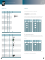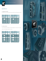
1
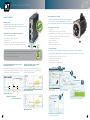
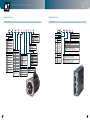
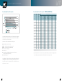
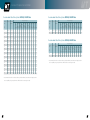
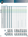
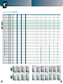
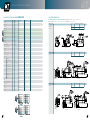
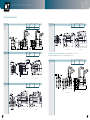
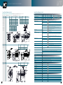
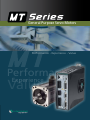
General Purpose Servo Motors Performance - Experience - Value Performance Value Experience General Purpose Servo Motors The MT Series Servo Solution General Purpose Servo Motors Closing the price-performance gap between induction motors and high-end servo motors, MT servo motors are particularly suitable for price sensitive motion applications that require efficient servo performance and functionality. The combined MT motors and CDHD drives deliver an economical servo solution for a variety of general purpose motion applications. Contents The MT Series Servo Solution..............................1 Drive and Motor Combinations .........................2 Features and Benefits ……................................ 4 Navigate the Catalog .........................................6 Ordering Information .........................................8 Recommended Motor/Drive Systems ..............10 Servo Motor Performance Data .......................14 Servo Motor Dimensions .................................19 Servo Drive Performance Data .........................23 Servo Drive Dimensions ...................................24 Typical System Wiring Diagram ........................26 Servo Drive Pin Assignments ............................27 Cables ..............................................................33 Optional Accessories ........................................34 Feedback Device................................................35 Input Voltage AC 120/240 VAC, 400/480 VAC CDHD Servo Drive Current: 1.5 Arms - 30 Arms MT Servo Motor Frame Size: 42 mm - 180 mm Rated Output 50 W - 4.5 kW, 0.16 Nm - 28 Nm 1 General Purpose Servo Motors Servo Drive Drive and Motor Combinations 120/240 VAC 3A CDHD-003 2A 4.5A CDHD-4D5 2A 6A CDHD-006 2A 8A CDHD-008 2A 10A CDHD-010 2A 13A CDHD-013 2A 20A CDHD-020 2A 24A CDHD-MV-024 50W MT-C04051C 200W MT-D06201C 550W/750W MT-D08751C 80W/100W MT-C04101C 250W/400W MT-C06401C 500W/750W MT-C08751C 200W MT-C06201C 400W MT-D06401C Medium Inertia Low Inertia Servo Motor 1.5A CDHD-1D5 2A 230W/300W MT-B07301C 2.7kW/4.5kW MT-C18452H 410W/550W MT-B13551A 500W/1kW MT-B13102A 750W/1.5kW MT-B13152A 420W/750W MT-B08751C 550W/1kW MT-B13102B 975W/1.5kW MT-B13152B 1kW/2kW MT-B13202B 1.65kW/3kW MT-B13302B 1.8kW/3kW MT-B13302C High Inertia 800W/1.5kW MT-B13152C 1.8kW/3kW MT-A18302H 2.35kW/4.4kW MT-A18442H Servo Drive Drive and Motor Combinations 400/480 VAC Medium Inertia ue re q On re q ue st 12A CDHD-012 4D st 6A CDHD-006 4D On Servo Motor 3A CDHD-003 4D 1.5 kW MT-B13152C 2 kW MT-B13202C * Additional 400/480 VAC motor types are available upon request. 2 3 General Purpose Servo Motors Features and Benefits MT rotary brushless servo motor CDHD servo drive servo motors, MT servo motors are particularly suitable for price sensitive Closing the price-performance gap between induction motors and high-end Hardware and software design innovations deliver superior servo motion applications that require efficient servo performance and functionality. performance, high power density, simple commissioning, and extensive Broad range of motor options versatility in a cost-effective package. • 7 frame sizes • Winding options for 160, 320, 560 and 640 VDC • Standard feedback options include incremental encoders with 2500 C/T or 8192 C/T and absolute encoders with up to 17 bit resolution • Standard and high inertia options • Optional holding brake • Up to protection class IP67 • Insulation class B (130°C) or F (155°C) Supporting a wide range of application requirements • Interfaces multiple feedback devices • I/O programming for any drive functionality • Safe Torque Off (STO) • Analog commands, Pulse & Direction, CANopen® and EtherCAT® • Fast firmware modifications to meet particular application needs ServoStudio™ wizard New current loop design achieves an industry-leading frequency response of 3-5 kHz High sampling rates and fl exible filtering options provide a faster response, and ensure maximum machine accuracy and throughput. 5 Advanced autotuning minimizes position error and settling time to almost zero Innovative anti-vibration control algorithm eliminates mechanical resonance Engineering experience and expertise has been implemented An active non-linear algorithm eliminates vibration in in a sophisticated autotuning function that performs optimal highly flexible resonant systems. Commissioning is easy, configurations for a difference making performance. using just a few gain parameters. User-friendly Servo Studio software provides step-by-step guidance through the setup and tuning process. Setup and testing are simplified thanks to auto-tuning functions and graphic representations of control loops. • Excellent results within minutes, even for novice users! • Real-time data recording and plotting • Easy integration of servo axes • Plug-and-play motor and feedback wiring Motor Selection 1 Load Estimation 2 Gain Optimization Without anti-vibe control Minimum position error Select motor part number as appears on the motor label. Test Quality of Motion Settling time of almost zero No oscillations at stand-still 3 Machine load is automatically estimated using a unique Servotronix algorithm. 4 Automatic tuning of all position loop control parameters. With anti-vibe control 4 Visualize the quality of motion, with graphic indication of zero settling time and minimal position error. 5 General Purpose Servo Motors Navigate the Cataog - 6 steps to ordering a complete system 1 Select Initial Combination General Purpose Servo Motors 2 Get Base Model Numbers 3 Ordering Information Motor Part Number Complete MT Servo Motor Select power range, voltage input and inertia level. General Purpose Servo Motors Select motor and matching drive from the relevant voltage inputGeneral table. Purpose Servo Motors Select brake, feedback and IP options. Recommended Motor/Drive Systems: Pages 11-13 Ordering Information: Page 8 MT Series Synchronous Servo Motors Drive and Motor Combinations: Pages 2-3 Recommended Motor/Drive Systems 120 VAC, 160 VDC bus Drive and Motor Combinations 120/240 VAC M o t o r Pa r a m e t e r s Servo Drive Motor Rated Power [W] 4.5A CDHD-4D5 2A 6A CDHD-006 2A 80 8A CDHD-008 2A 200 50W MT-C04051C 200W MT-D06201C 550W/750W MT-D08751C 80W/100W MT-C04101C 250W/400W MT-C06401C 500W/750W MT-C08751C 200W MT-C06201C 400W MT-D06401C Medium Inertia Low Inertia Servo Motor 3A CDHD-003 2A 230W/300W MT-B07301C 410W/550W MT-B13551A 500W/1kW MT-B13102A 750W/1.5kW MT-B13152A 420W/750W MT-B08751C 550W/1kW MT-B13102B 975W/1.5kW MT-B13152B High Inertia 800W/1.5kW MT-B13152C Servo Drive Drive and Motor Combinations 400/480 VAC 12A CDHD-012 4D MT-D06201C CDHD-1D5 CDHD-003 Low Low on So g in m Complete Drive Part Number 1.5 kW MT-B13152C 4 B Medium inertia (300 to 3000 W motors) C Low inertia (50 to 750 W and 4.5 kW motors, except 550 W) D Low inertia (small size) (200 to 750 W motors, except 550 W) Mmax Nmax In Imax J 04 42 mm (50 to 100 W motors) [N-m] [N-m] [N-m] [N-m] [rpm] [rpm] [rpm] [Arms] [Arms] [kg-cm2] 06 60 mm (200 to 400 W motors) 42 0.960 0.419 0.320 0.266 2400 1200 2600 0.94 2.82 0.036 07 76 mm (300 W motor) 2700 3700 2.10 6.30 0.164 08 80 mm (MT-C08) (750 W motor) 60 1.911 0.899 Rated Rated Torque Speed at Knee Tcnmax mn Max Knee Speed Np Max Speed Rated Max Current Current Rotor Inertia Frame Size 0.637 0.465 3000 200 MT-C06201C CDHD-1D5* Low 60 1.911 0.873 0.637 0.478 3000 2300 3600 1.80 5.40 0.170 230 MT-B07301C CDHD-003 Medium 76 2.861 1.319 0.950 0.756 2300 1900 2600 2.00 6.00 0.677 400 MT-D06401C CDHD-003* Low 60 3.820 1.294 1.274 0.819 3000 3300 4200 3.50 11.10 0.290 250 MT-C06401C CDHD-003 Low 60 3.820 1.354 1.274 0.934 1900 1300 2300 2.50 7.50 0.280 410 MT-B13551A CDHD-4D5 Medium 130.4 15.756 6.327 5.252 4.431 750 500 800 3.43 10.30 6.260 550 MT-D08751C CDHD-4D5 Low 80 7.161 3.762 2.387 1.750 2200 2000 2700 4.80 14.40 0.907 500 MT-C08751C CDHD-4D5 Low 80 7.161 3.156 2.387 1.790 2000 1800 2400 4.30 12.90 12.140 420 MT-B08751C CDHD-4D5 Medium 86 7.161 3.407 2.387 1.826 1700 1600 2000 3.75 11.25 2.459 500 MT-B13102A CDHD-006 Medium 130.4 28.635 10.539 9.545 6.136 500 500 700 5.16 15.50 0.940 550 MT-B13102B CDHD-006 Medium 130.4 14.346 8.015 4.782 3.382 1100 1200 1400 5.16 15.48 6.260 750 MT-B13152A CDHD-008 Medium 130.4 42.981 21.470 14.327 9.919 500 550 650 7.45 22.35 17.920 975 MT-B13152B CDHD-008 Medium 130.4 21.492 11.089 7.164 5.987 1300 1200 1400 7.57 22.71 8.880 800 MT-B13152C CDHD-008 Medium 130.4 14.346 8.229 4.782 3.443 1600 1800 2000 7.06 21.80 6.260 1000 MT-B13202B CDHD-010* Medium 130.4 28.635 14.107 9.545 6.608 1000 1150 1300 9.18 27.50 12.140 1650 MT-B13302B CDHD-013* Medium 130.4 42.981 26.147 14.327 10.911 1100 1150 1300 14.00 42.00 17.920 1800 MT-B13302C CDHD-013* Medium 130.4 28.635 19.230 9.545 7.731 1900 2000 14.00 42.00 12.140 1800 MT-A18302H CDHD-020 High 180 49.500 32.497 19.100 13.453 900 1050 1150 15.00 39.00 39.990 2350 MT-A18442H CDHD-024* High 180 71.500 38.981 28.000 17.530 800 1000 1150 22.50 58.50 51.440 2700 MT-C18452H CDHD-024* Low 180 64.123 47.288 28.600 18.533 900 1100 1250 25.20 56.50 31.600 1800 motor capability. The system performance will be below the motor’s given values. Add Cable Part Numbers 2 kW MT-B13202C Ordering Information 08 5 86 mm (MT-B08) (750 W motor) 13 130.4 mm (550 to 3000 W motors) 18 180 mm (550 to 3000 W motors) ! 1 No IP67 (Inertia D) C IP67 with oil seal (Inertia A, B, C, except 50 W motors) D IP67 without oil seal (Inertia A, B, C, except 50 W motors) Connector 3 300 mm with AMP (50 to 750 W motors) A Round Military (650 to 4500 W motors) Rated Output * 051 50 W 101 100 W 201 200 W 301 300 W 401 400 W 551 550 W 751 750 W 102 1 kW 152 1.5 kW 202 2 kW 302 3 kW 442 4.4 kW 452 4.5 kW Feedback Device Motor Bus Voltage 2 4 * Motor voltage 320 VDC. For other motor output rates, refer to motor performance data tables. 160 VDC : 120 VAC line-line input 1 or 3 phase 320 VDC : 240 VAC line-line input 1 or 3 phase 560 VDC: 380 VAC line-line input 3 phase 640 VDC: 480 VAC line-line input 3 phase T Tamagawa 2500 C/T Y Tamagawa 8192 C/T 5* Tamagawa 15 bit multi turn 7 Tamagawa 17 bit single turn M* Tamagawa 17 bit multi turn 4* Revolver * Special order Rated Speed Brake A 1000 rpm (550 to 1500 W motors) N Without brake (all motors) H 1500 rpm (1 to 3 kW motors) B With brake (24 VDC; all motors, except MT-C18452H) B 2000 rpm (50 to 3000 W motors, except 550 W) C 3000 rpm (3 to 4.5 kW motors) Having trouble finding the perfect match for your application? Make sure motor meets your needs: Performance Data - Pages 14-18 Dimensions - Pages 19-22 Feedback Information - Pages 35-36 8 Optional Controller Cables and Accessories 6 CDHDinterface Servo Drive Select options and number of analog inputs. 2 Select power and feedback cables according to specifications and length. Ordering Information: Page 9 Cables: Page 33 Select controller cables with flying leads and kit connectors for CDHD power stage. General Purpose Servo Motors Controller Cables: Page 33 Optional Accessories: Page 34 Cables Optional Accessories CDHD Servo Drive – HD Series Rating Analog Input 0 Power block 1 One analog input, 16 bit 2 Two analog inputs, 14 bit each 120/240 VAC Dauer.str. [Aeff] Spitzen.str [Aeff] 1D5 1.5 4.5 AP * 003 3 9 AF * Analog Voltage, Pulse Train Ref, CANopen, USB, RS232 4D5 4.5 18 EC ** EtherCAT, USB, RS232 006 6 18 PB *** PWM Power Block 008 8 28 010 10 28 013 13 28 * Standard configuration with one analog input ** Standard configuration with two analog inputs *** PB0 and PWM power block do not have analog input option 020 20 48 024 24 48 400/480 VAC Cont [A rms] Peak [A rms] 3 9 006 6 18 012 12 24 024 24 72 030 30 90 003 Interface Options Analog Voltage, Pulse Train Ref, RS232 10 AC and Controller Input Power Supply 2A Input Single Phase 120 L-L VAC +10% -15% 50/60 Hz Input Single Phase 240 L-L VAC +10% -15% 50/60 Hz Input Three Phase 120-240 L-L VAC +10% -15% 50/60 Hz 4D AC Input Power Supply: - Input Three Phase 400 L-L VAC +10% -15% 50/60 Hz - Input Three Phase 480 L-L VAC +10% -15% 50/60 Hz 24 VDC input for control board power supply ! Make sure drive meets your needs: Performance Data - Page 23 Dimensions - Pages 24-25 9 Contact us at [email protected] or contact your local Servotronix distributor Controller cables with flying leads Length CDHD connector (Unit: m) Model Specifications CBL-MDRFL-36-01 CBL-MDRFL-36-02 CBL-MDRFL-36-03 MDR 36 and flying leads cable. Controller I/F C2 1 2 3 CBL-MDRFL-20-01 CBL-MDRFL-20-02 CBL-MDRFL-20-03 MDR 20 and flying leads cable. Machine I/F C3 CBL-MDRFL-26-01 CBL-MDRFL-26-02 CBL-MDRFL-26-03 MDR 26 and flying leads cable. Motor feedback C4 Appearance CDHD configuration Connectors Model Specification KIT-2A-PWSPR-00* CDHD Power Mating Spring 120/240VAC CDHD-1D5 CDHD-003 P2 P3 1 2 3 KIT-2A-POWER-00 CDHD Power Mating Crimp 120/240VAC CDHD-1D5 CDHD-003 P2 P3 1 2 3 KIT-2B-PWSPR-00* CDHD Power Mating Spring 120/240VAC CDHD-4D5 CDHD-006 P2 P3 P4 KIT-2B-POWER-00 CDHD Power Mating Crimp 120/240VAC CDHD-4D5 CDHD-006 P2 P3 P4 KIT-2C-POWER-00* CDHD Power Mating Crimp 120/240VAC CDHD-008 CDHD-010 CDHD-013 P2 P3 P4 P5 Motor power (UVW) cables 120/240 VAC 6 High inertia (3 and 4.4 kW motors) [mm] Peak Torque * Recommended servo drive continuous and/ or peak (intermittent) current values are slightly less than Co m in g So on 6A CDHD-006 4D Co Servo Motor 3A CDHD-003 4D MT-C04101C A Rated Max Torque Torque at Knee Tinmax Mn Frame Size Pn 1.5A CDHD-1D5 2A Medium Inertia Motor Model Recommended Inertia Servo Drive Seal Inertia Length CDHD Motor connector configuration (Unit: m) Model Specifications CBL-P2AN3N00-01 CBL-P2AN3N00-02 CBL-P2AN3N00-03 Motor power (UVW) cable without shield. Conductor size AWG (mm2) 18 (0.8) AMP 120/240 VAC CDHD-1D5 CDHD-003 1 2 3 CBL-P2BN3N00-01 CBL-P2BN3N00-02 CBL-P2BN3N00-03 Motor power (UVW) cable without shield. Conductor size AWG (mm2) 16 (1.3) AMP 120/240 VAC CDHD-4D5 CDHD-006 1 2 3 KIT-2D-PWSPR-00* CDHD Power Mating Spring 120/240VAC CDHD-020 CDHD-024 P2 P3 P4 P5 CBL-P2BNAS00-01 CBL-P2BNAS00-02 CBL-P2BNAS00-03 Motor power (UVW) cable with MIL shield without brake. Conductor size AWG (mm2) 16 (1.3) 120/240 VAC CDHD-4D5 CDHD-006 1 2 3 KIT-4A-PWSPR-00 CDHD Power Mating Spring 400/480VAC CDHD-003 CDHD-006 CDHD-012 P2 P3 P4 P5 CBL-P2BBAS00-01 CBL-P2BBAS00-02 CBL-P2BBAS00-03 Motor power (UVW) cable with MIL brake and shield. Conductor size AWG (mm2) 16 (1.3) brake 120/240 VAC CDHD-4D5 CDHD-006 1 2 3 CBL-P2CNAS00-01 CBL-P2CNAS00-02 CBL-P2CNAS00-03 Motor power (UVW) cable with shield without brake. Conductor size AWG (mm2) 14 (2) MIL 120/240 VAC CDHD-008 CDHD-010 CDHD-013 1 2 3 CBL-P2CBAS00-01 CBL-P2CBAS00-02 CBL-P2CBAS00-03 Motor power (UVW) cable with MIL brake and shield. Conductor size AWG (mm2) 14 (2) 120/240 VAC CDHD-008 CDHD-010 CDHD-013 1 2 3 Appearance *Included with the product when ordered. Motor feedback cables Motor connector Length CDHD configuration (Unit: m) All Model Specifications CBL-F-T-3-00-01 CBL-F-T-3-00-02 CBL-F-T-3-00-03 Motor feedback cable with shield for Tamagawa incremental encoder 2500 C/T and 8192 C/T AMP CBL-F-7-3-00-01 CBL-F-7-3-00-02 CBL-F-7-3-00-03 Motor feedback cable with shield for Tamagawa absolute 17 encoder AMP Picture Appearance Picture Model Specification Connectors KIT-USBRS232-00 Adapter Cables Kit-PC USB type A to RS232 C7 KIT-24VBRAKE-00 Brake Circuit Kit - CBLr0000USBA-00 USB Cable, PC type A to Mini-B, 1.5m C1 CONr00000004-AS STO Jumper Connector P1 PRO - P.56 CONr10000004-09 STO Connector P1 PRO - P.56 PINr43030000-00 STO Connector Crimp (4 crimps required) P1 PRO - P.56 1 2 3 All 1 2 7 General Purpose Servo Motors Ordering Information Ordering Information MT Servo Motor CDHD Servo Drive CDHD Servo Drive – HD Series MT Series Synchronous Servo Motors Inertia A High inertia (3 and 4.4 kW motors) B Medium inertia (300 to 3000 W motors) C Low inertia (50 to 750 W and 4.5 kW motors, except 550 W) D Low inertia (small size) (200 to 750 W motors, except 550 W) Frame Size 04 42 mm (50 to 100 W motors) 06 60 mm (200 to 400 W motors) 07 76 mm (300 W motor) 08 80 mm (MT-C08) (750 W motor) 08 13 18 8 86 mm (MT-B08) (750 W motor) 130.4 mm (550 to 3000 W motors) 180 mm (550 to 3000 W motors) Analog Input Seal 1 No IP67 (Inertia D) C IP67 with oil seal (Inertia A, B, C, except 50 W motors) D IP67 without oil seal (Inertia A, B, C, except 50 W motors) Connector 3 300 mm with AMP (50 to 750 W motors) A Round Military (650 to 4500 W motors) Rated Output * 051 50 W 101 100 W 201 200 W 301 300 W 401 400 W 551 550 W 751 750 W 102 1 kW 152 1.5 kW 202 2 kW 302 3 kW 442 4.4 kW 452 4.5 kW * Motor voltage 320 VDC. For other motor output rates, refer to motor performance data tables. 4 160 VDC : 120 VAC line-line input 1 or 3 phase 320 VDC : 240 VAC line-line input 1 or 3 phase 1D5 1.5 4.5 AP * Analog Voltage, Pulse Train Ref, RS232 003 3 9 AF * Analog Voltage, Pulse Train Ref, CANopen, USB, RS232 4D5 4.5 18 EC ** EtherCAT, USB, RS232 006 6 18 PB *** PWM Power Block 008 8 28 010 10 28 013 13 28 * Standard configuration with one analog input ** Standard configuration with two analog inputs *** PB0 and PWM power block do not have analog input option 020 20 48 024 24 48 400/480 VAC 560 VDC: 380 VAC line-line input 3 phase 640 VDC: 480 VAC line-line input 3 phase 3 9 006 6 18 012 12 24 Tamagawa 17 bit multi turn 024 24 72 Revolver 030 30 90 Y Tamagawa 8192 C/T 5* Tamagawa 15 bit multi turn 7 Tamagawa 17 bit single turn M* 4* Two analog inputs, 14 bit each Spitzen.str [Aeff] Peak [A rms] Tamagawa 2500 C/T One analog input, 16 bit 2 Dauer.str. [Aeff] Cont [A rms] T Power block 1 120/240 VAC Feedback Device Motor Bus Voltage 2 Rating 0 003 Interface Options AC and Controller Input Power Supply 2A Input Single Phase 120 L-L VAC +10% -15% 50/60 Hz Input Single Phase 240 L-L VAC +10% -15% 50/60 Hz Input Three Phase 120-240 L-L VAC +10% -15% 50/60 Hz 4D AC Input Power Supply: - Input Three Phase 400 L-L VAC +10% -15% 50/60 Hz - Input Three Phase 480 L-L VAC +10% -15% 50/60 Hz 24 VDC input for control board power supply * Special order Rated Speed Brake A 1000 rpm (550 to 1500 W motors) N Without brake (all motors) H 1500 rpm (1 to 3 kW motors) B With brake (24 VDC; all motors, except MT-C18452H) B 2000 rpm (50 to 3000 W motors, except 550 W) C 3000 rpm (3 to 4.5 kW motors) 9 General Purpose Servo Motors Recommended Motor/Drive Systems Recommended Motor/Drive Systems 120 VAC, 160 VDC bus M o t o r Pa r a m e t e r s Motor Rated Power Motor Model Recommended Inertia Servo Drive Mmax Rated Max Torque Torque at Knee Tinmax Mn Nmax In Imax J [mm] [N-m] [N-m] [N-m] [N-m] [rpm] [rpm] [rpm] [Arms] [Arms] [kg-cm2] Frame Size Pn [W] Peak Torque Rated Rated Torque Speed at Knee Tcnmax Mn Max Knee Speed Np Max Speed Rated Max Current Current Rotor Inertia 80 MT-C04101C CDHD-1D5 Low 42 0.960 0.419 0.320 0.266 2400 1200 2600 0.94 2.82 0.036 200 MT-D06201C CDHD-003 Low 60 1.911 0.899 0.637 0.465 3000 2700 3700 2.10 6.30 0.164 200 MT-C06201C CDHD-1D5* Low 60 1.911 0.873 0.637 0.478 3000 2300 3600 1.80 5.40 0.170 230 MT-B07301C CDHD-003 Medium 76 2.861 1.319 0.950 0.756 2300 1900 2600 2.00 6.00 0.677 400 MT-D06401C CDHD-003* Low 60 3.820 1.294 1.274 0.819 3000 3300 4200 3.50 11.10 0.290 250 MT-C06401C CDHD-003 Low 60 3.820 1.354 1.274 0.934 1900 1300 2300 2.50 7.50 0.280 410 MT-B13551A CDHD-4D5 Medium 130.4 15.756 6.327 5.252 4.431 750 500 800 3.43 10.30 6.260 550 MT-D08751C CDHD-4D5 Low 80 7.161 3.762 2.387 1.750 2200 2000 2700 4.80 14.40 0.907 500 MT-C08751C CDHD-4D5 Low 80 7.161 3.156 2.387 1.790 2000 1800 2400 4.30 12.90 12.140 420 MT-B08751C CDHD-4D5 Medium 86 7.161 3.407 2.387 1.826 1700 1600 2000 3.75 11.25 2.459 500 MT-B13102A CDHD-006 Medium 130.4 28.635 10.539 9.545 6.136 500 500 700 5.16 15.50 0.940 550 MT-B13102B CDHD-006 Medium 130.4 14.346 8.015 4.782 3.382 1100 1200 1400 5.16 15.48 6.260 750 MT-B13152A CDHD-008 Medium 130.4 42.981 21.470 14.327 9.919 500 550 650 7.45 22.35 17.920 975 MT-B13152B CDHD-008 Medium 130.4 21.492 11.089 7.164 5.987 1300 1200 1400 7.57 22.71 8.880 800 MT-B13152C CDHD-008 Medium 130.4 14.346 8.229 4.782 3.443 1600 1800 2000 7.06 21.80 6.260 1000 MT-B13202B CDHD-010* Medium 130.4 28.635 14.107 9.545 6.608 1000 1150 1300 9.18 27.50 12.140 1650 MT-B13302B CDHD-013* Medium 130.4 42.981 26.147 14.327 10.911 1100 1150 1300 14.00 42.00 17.920 Mmax - Maximum torque of the motor 1800 MT-B13302C CDHD-013* Medium 130.4 28.635 19.230 9.545 7.731 1900 2000 14.00 42.00 12.140 Minmax - Intermittent torque at maximum speed 1800 MT-A18302H CDHD-020 High 180 49.500 32.497 19.100 13.453 900 1050 1150 15.00 39.00 39.990 Mcmax - Continuous torque at maximum speed 2350 MT-A18442H CDHD-024* High 180 71.500 38.981 28.000 17.530 800 1000 1150 22.50 58.50 51.440 Mn - Continuous rated torque 2700 MT-C18452H CDHD-024* Low 180 64.123 47.288 28.600 18.533 900 1100 1250 25.20 56.50 31.600 The system torque/speed information on the following pages is designed to help you select the optimum combination of brushless servo motor/drive. The nominal values in this data illustrate performance for the recommended motor/drive system. 1800 Nn - Rated speed Np - Speed at knee in maximum envelope (intersection of motor max torque with voltage limit line) Nmax - Maximum speed * Recommended servo drive continuous and/ or peak (intermittent) current values are slightly less than motor capability. The system performance will be below the motor’s given values. The combination of the MT Series motors and the reliable and feature-rich CDHD digital drive amplifier meets virtually any kind of application with torque from 0.16 N-m to 28 N-m, max speed of 6000 RPM, motor power rating from 50W to 4.5kW. 10 11 General Purpose Servo Motors Recommended Motor/Drive Systems 240 VAC, 320 VDC bus Recommended Motor/Drive Systems 400 VAC, 560 VDC bus M o t o r Pa r a m e t e r s Motor Rated Power Motor Model Recommended Inertia Servo Drive Mmax Rated Max Torque Torque at Knee Tinmax Mn Nmax In Imax J Pn [mm] [N-m] [N-m] [N-m] [N-m] [rpm] [rpm] [rpm] [Arms] [Arms] [kg-cm2] [W] Frame Size Pn [W] M o t o r Pa r a m e t e r s Motor Rated Power Peak Torque Rated Rated Torque Speed at Knee Tcnmax Mn Max Knee Speed Np Max Speed Rated Max Current Current Rotor Inertia Motor Model Recommended Inertia Servo Drive Mmax Rated Max Torque Torque at Knee Tinmax Mn Nmax In Imax J [mm] [N-m] [N-m] [N-m] [N-m] [rpm] [rpm] [rpm] [Arms] [Arms] [kg-cm2] Frame Size Peak Torque Rated Rated Torque Speed at Knee Tcnmax Mn Max Knee Speed Np Max Speed Rated Max Current Current Rotor Inertia 50 MT-C04051C CDHD-1D5 Low 42 0.480 0.215 0.160 0.096 3000 2500 4500 0.65 1.95 0.029 1500 MT-B13152C CDHD-006 Medium 130.4 14.327 6.350 4.782 3.587 3000 3800 4000 3.95 11.85 6.260 100 MT-C04101C CDHD-1D5 Low 42 0.960 0.766 0.320 0.173 3000 4000 5000 0.94 2.82 0.036 2000 MT-B13202C CDHD-006 Medium 130.4 19.080 8.440 6.360 4.540 3000 4000 4200 5.54 16.62 12.140 200 MT-D06201C CDHD-003 Low 60 1.911 0.873 0.637 0.287 3000 5000 6000 2.10 6.30 0.164 200 MT-C06201C CDHD-1D5* Low 60 1.911 0.774 0.637 0.287 3000 5000 6000 1.80 5.40 0.170 300 MT-B07301C CDHD-003 Medium 76 2.861 1.767 0.950 0.493 3000 4100 5200 2.00 6.00 0.677 400 MT-D06401C CDHD-003* Low 60 3.820 2.094 1.274 0.573 3000 5000 6000 3.50 11.10 0.290 400 MT-C06401C CDHD-003 Low 60 3.820 2.142 1.274 0.764 3000 3700 4500 2.50 7.50 0.280 550 MT-B13551A CDHD-4D5 Medium 130.4 15.756 8.734 5.252 2.954 1000 1200 1600 3.43 10.30 6.260 750 MT-D08751C CDHD-4D5 Low 80 7.173 3.566 2.391 1.196 3000 4400 5400 4.80 14.40 0.907 750 MT-C08751C CDHD-4D5 Low 80 7.173 3.896 2.391 1.345 3000 4200 4800 4.30 12.90 12.140 750 MT-B08751C CDHD-4D5 Medium 86 7.173 3.108 2.391 1.575 3000 3600 4100 3.75 11.25 2.459 1000 MT-B13102A CDHD-006 Medium 130.4 28.635 11.928 9.545 6.136 1000 1100 1400 5.16 15.50 12.140 1000 MT-B13102B CDHD-006 Medium 130.4 14.346 5.164 4.782 2.968 2000 2200 2900 5.16 15.48 6.260 1500 MT-B13152A CDHD-008 Medium 130.4 42.981 28.127 14.327 9.919 1000 1150 1300 7.45 22.35 17.920 1500 MT-B13152B CDHD-008 Medium 130.4 21.492 11.197 7.164 4.605 2000 2400 2800 7.57 22.71 8.880 1500 MT-B13152C CDHD-008 Medium 130.4 14.346 6.950 4.782 3.228 3000 3500 4000 7.06 21.80 6.260 2000 MT-B13202B CDHD-010* Medium 130.4 28.635 16.927 9.545 6.738 2000 2300 2550 9.18 27.50 12.140 3000 MT-B13302B CDHD-013* Medium 130.4 42.981 24.124 14.327 9.919 2000 2400 2600 14.00 42.00 17.920 3000 MT-B13302C CDHD-013* Medium 130.4 28.635 13.157 9.545 6.443 3000 3600 4000 14.00 42.00 12.140 3000 MT-A18302H CDHD-020 High 180 49.500 38.352 19.100 11.615 1500 1800 2220 15.00 39.00 39.990 4400 MT-A18442H CDHD-024* High 180 71.500 53.557 28.000 17.182 1500 1800 2200 22.50 58.50 51.440 4500 MT-C18452H CDHD-024* Low 180 64.123 55.695 28.600 15.759 1500 2000 2450 25.20 56.50 31.600 Recommended Motor/Drive Systems 480 VAC, 640 VDC bus M o t o r Pa r a m e t e r s Motor Rated Power Motor Model Recommended Inertia Servo Drive Mmax Rated Max Torque Torque at Knee Tinmax Mn Nmax In Imax J [mm] [N-m] [N-m] [N-m] [N-m] [rpm] [rpm] [rpm] [Arms] [Arms] [kg-cm2] Frame Size Pn [W] Peak Torque Rated Rated Torque Speed at Knee Tcnmax Mn Max Knee Speed Np Max Speed Rated Max Current Current Rotor Inertia 1500 MT-B13152C CDHD-006 Medium 130.4 14.327 7.740 4.782 3.000 3000 4430 4750 3.95 11.85 6.260 2000 MT-B13202C CDHD-006 Medium 130.4 19.080 9.500 6.360 3.816 3000 4700 5000 5.54 16.62 12.140 * Recommended servo drive continuous and/ or peak (intermittent) current values are slightly less than motor capability. The system performance will be below the motor’s given values. * Recommended servo drive continuous and/ or peak (intermittent) current values are slightly less than motor capability. The system performance will be below the motor’s given values. 12 13 General Purpose Servo Motors Servo Motor Performance Data 160/320 VDC MT-C04051C MT-C04101C MT-C06201C MT-C06401C MT-D06201C MT-D06401C MT-B07301C MT-C08751C MT-B08751C MT-D08751C MT-B13551A N-m 0.48 0.96 1.91 3.82 1.91 3.82 2.86 7.17 7.17 7.17 15.76 Rated Current Ir Arms 0.65 0.94 1.80 2.50 2.10 3.50 2.00 4.30 3.75 4.80 3.43 Max Current Imax Arms 1.95 2.82 5.40 7.50 6.30 11.10 6.00 12.90 11.25 14.40 10.30 Rated Torque Tr N-m 0.16 0.32 0.64 1.27 0.64 1.27 0.95 2.39 2.39 2.39 5.25 3000 2300 2000 1700 2200 750 420 550 410 160 VDC Units Tmax Rated Speed Nr RPM N/A 2400 3000 1900 3000 Rated Output Pr W N/A 80 200 250 200 400 230 500 Max Speed Nmax RPM N/A 2600 3600 2300 3600 4200 2600 2400 2000 2700 800 320 VDC Symbol Max Torque Rated Speed Nr RPM 3000 3000 3000 3000 3000 3000 3000 3000 3000 3000 1000 Rated Output Pr W 50 100 200 400 200 400 300 750 750 750 550 Max Speed Nmax RPM 4500 5000 6000 4500 6000 6000 5200 4800 4100 5400 1600 Constant Torque Kt N-m/Arms 0.39 0.38 0.30 0.53 0.34 0.37 0.50 0.53 0.70 0.54 1.68 22.20 31.67 35.28 42.50 Back EMF Constant Ke V/krpm 25.00 24.44 21.33 35.28 22.20 32.80 101.56 Rotor Inertia Without Brake Jm x10-4•Kg•m2 0.03 0.04 0.17 0.28 0.16 0.29 0.68 0.94 2.46 0.91 6.26 Resistance Ra Ω 71.00 24.00 7.50 5.60 4.74 1.87 5.00 2.10 2.18 1.15 3.58 Inductance La mH 78.00 35.00 16.20 14.50 9.60 4.22 11.60 8.63 7.70 4.74 18.33 Mechanical Time Constant Tm ms 1.93 0.90 0.74 0.84 0.70 0.48 2.07 0.80 1.64 0.42 1.19 Electrical Time Constant Te ms 1.10 1.46 2.16 2.59 2.16 2.25 2.32 4.11 3.53 4.11 5.12 Insulation Grade - - B B F F F F F F F F B DC 24 DC 24 DC 24 DC 24 Brake Feedback Rated Voltage V DC 24 DC 24 DC 24 DC 24 DC 24 DC 24 DC 24 Static Rubbing Torque N-M 0.35 0.35 2 2 2 2 2 3 3 3 3 Inertia x10-4•Kg•m2 0.01 0.01 0.05 0.05 0.05 0.05 0.05 0.13 0.13 0.13 0.13 Current disipation A 0.25 0.25 0.26 0.26 0.26 0.26 0.26 0.43 0.82 0.82 0.82 Time for brake funtion ms 15 15 17 17 17 17 17 35 27 27 27 Time for brake release ms 118 118 32 32 32 32 32 25 76 76 76 YES YES YES YES YES YES YES YES YES YES YES NO YES YES YES Incremental 2500 C/T Incremental 8192 C/T NO NO YES YES NO NO YES Absolute 17 bit YES YES YES YES YES YES YES YES YES YES YES Resolver Option Option Option Option Option Option Option Option Option Option Option 8 8 8 8 14 14 8 8 8 14 8 IP67 IP67 IP67 IP67 NO NO IP67 IP67 IP67 NO IP67 NO NO Option Option NO NO Option Option Option Option Option 0.48 0.65 1.03 1.37 0.90 1.20 1.82 2.05 3.41 2.20 6.47 257.74 298.90 156.80 436.10 436.10 813.00 63.70 98.00 78.40 147.00 147.00 196.00 Poles Degree of Protection Degree (IP) IP Oil Seal at Shaft Weight W kg N 75.46 75.46 257.74 257.74 Axial Force N 34.30 34.30 63.70 63.70 63.70 320 VDC 160 VDC Radial Force 257.74 14 15 General Purpose Servo Motors Servo Motor Performance Data 160/320 VDC Cont. Symbol Units MT-B13102A MT-B13102B MT-B13152A MT-B13152B MT-B13152C MT-B13202B MT-B13302B MT-B13302C MT-A18302H MT-A18442H MT-C18452H Max Torque Tmax N-m 28.64 14.35 42.98 21.49 14.35 28.64 42.98 28.64 49.50 71.50 64.12 Rated Current Ir Arms 5.16 5.16 7.45 7.57 7.06 9.18 14.00 14.00 15.00 22.50 25.20 Max Current Imax Arms 15.50 15.48 22.35 22.71 21.80 27.50 42.00 42.00 39.00 58.50 56.50 Rated Torque Tr N-m 9.55 4.78 14.33 7.16 4.78 9.55 14.33 9.55 19.10 28.00 28.60 1300 1600 1000 1100 1800 900 800 900 975 800 1000 1650 1800 1800 2350 2700 1150 1250 500 1100 Pr W 500 550 750 160 VDC RPM Rated Output Rated Speed Max Speed Nmax RPM 700 1400 650 1400 2000 1300 1300 2000 1150 320 VDC Nr 500 Rated Speed Nr RPM 1000 2000 1000 2000 3000 2000 2000 3000 1500 1500 1500 Rated Output Pr W 1,000 1,000 1,500 1,500 1,500 2,000 3,000 3,000 3,000 4,400 4,500 Max Speed Nmax RPM 1400 2900 1300 2800 4000 2550 2600 4000 2220 2200 2450 Constant Torque Kt N-m/Arms 2.04 1.02 2.11 1.06 0.74 1.14 1.13 0.75 1.27 1.24 1.20 62.78 44.74 68.89 68.30 45.32 81.32 82.23 72.00 8.88 6.26 12.14 17.92 12.14 39.99 51.44 3.16 Back EMF Constant Ke V/krpm 123.33 61.67 127.78 Rotor Intertia Without Brake Jm x10-4•Kg•m2 12.14 6.26 17.92 Resistance Ra Ω 1.85 1.22 1.19 0.79 0.65 0.58 0.33 0.25 0.18 0.12 0.18 Inductance La mH 12.14 6.70 8.44 4.74 0.58 3.78 2.12 1.62 2.89 1.98 2.50 Mechanical Time Constant Tm ms 0.81 1.10 0.72 0.94 1.12 0.81 0.70 0.80 0.69 0.59 0.53 Electrical Time Constant Te ms 6.55 5.49 7.09 6.00 5.48 6.52 6.38 6.56 16.12 16.79 13.89 Insulation Grade - - B B B B B B B B F F F DC 24 DC 24 DC 24 DC 24 DC 24 DC 24 DC 24 - 20 20 20 20 20 40 40 - Brake Feedback Rated Voltage V DC 24 DC 24 DC 24 Static Rubbing Torque N-M 20 20 20 Inertia x10-4•Kg•m2 0.32 0.32 0.32 0.32 0.32 0.32 0.32 0.32 2.07 2.07 - Current disipation A 0.82 0.82 0.82 0.82 0.82 0.82 0.82 0.82 1.22 1.22 - Time for brake funtion ms 27 27 27 27 27 27 27 27 15 15 - Time for brake release ms 76 76 76 76 76 76 76 76 95 95 - YES YES YES YES YES YES YES YES YES YES YES YES YES YES YES YES YES NO YES YES YES YES YES YES YES Incremental 2500 C/T Incremental 8192 C/T YES YES YES YES Absolute 17 bit YES YES YES YES Resolver Poles Degree of Protection Degree (IP) IP Oil Seal at Shaft Weight W kg Option Option Option Option Option Option Option Option Option Option Option 8 8 8 8 8 8 8 8 8 8 14 IP67 IP67 IP67 IP67 IP67 IP67 IP67 IP67 IP67 IP67 NO Option Option Option Option Option Option Option Option Option Option Option 10.16 6.47 13.87 8.08 6.47 10.16 13.87 10.16 19.50 26.20 15.20 490.00 617.00 617.00 490.00 1107.40 1107.40 1107.40 147.00 157.00 157.00 147.00 294.00 294.00 294.00 N 813.00 617.00 813.00 Axial Force N 196.00 157.00 196.00 157.00 320 VDC 160 VDC Radial Force 617.00 16 17 General Purpose Servo Motors Servo Motor Performance Data 560/640 VDC Servo Motor Dimensions Motor Mating Connector for the following motors: Motor Power (U V W): CAP AMP 172159-1, Crimp AMP 170362-1 Motor Feedback: CAP AMP 172161-1, Crimp AMP 170361-1 Motor Brake: 2 separate flying leads Symbol Units MT-B13152C MT-B13202C Max Torque Tmax N-m 14.35 28.65 Rated Current Ir Arms 3.95 9.18 MTHD Servo Motor Model Max Current Imax Arms 11.85 27.50 MT-C04051C MT-C04051C 85.3 122.6 MT-C04101C MT-C04101C 106.3 143.6 Rated Torque Tr N-m 4.78 6.36 560 VDC Rated Speed Nr RPM 3,000 3,000 Rated Output Pr W 1,500 2,000 Max Speed Nmax RPM 4,000 4,300 640 VDC L (mm) Without Brake L (mm) With Brake Rated Speed Nr RPM 3,000 3,000 Rated Output Pr W 1,500 2,000 Max Speed Nmax RPM 4,500 4,700 Constant Torque Kt N-m/Arms 1.33 6.36 Back EMF Constant Ke V/krpm 80.61 76.30 Rotor Inertia Without Brake Jm x10-4•Kg•m2 6.26 12.14 Resistance Ra Ω 2.23 0.73 Inductance La mH 11.46 4.60 Mechanical Time Constant Tm ms 1.10 0.86 MTHD Servo Motor Model Electrical Time Constant Te ms 5.14 6.30 MT-C06201C MT-C06201C 112.8 Insulation Grade - Without Brake With Brake L (mm) Without Brake L (mm) With Brake - B B Rated Voltage V DC 24 DC 24 Static Rubbing Torque N-M 20 20 Inertia x10-4•Kg•m2 0.32 0.32 Current disipation A 0.82 0.82 Time for brake funtion ms 27 27 Time for brake release ms 76 76 Incremental 2500 C/T YES YES Incremental 8192 C/T YES YES Absolute 17 bit YES YES Resolver Option Option 8 8 IP67 IP67 Option Option MTHD Servo Motor Model kg 6.47 10.16 MT-C06401C MT-C06401C 132.8 Radial Force N 490.00 490.00 Axial Force N 147.00 147.00 Brake Feedback Poles Degree of Protection Degree (IP) IP Oil Seal at Shaft W With Brake L (mm) Without Brake L (mm) With Brake 167.3 640 VDC 560 VDC Weight Without Brake 147.3 18 Without Brake With Brake 19 General Purpose Servo Motors Servo Motor Dimensions Cont. MTHD Servo Motor Model L (mm) Without Brake L (mm) With Brake MT-D06201C MT-D06201C 80.5 117 MT-D06401C MT-D06401C 95.5 132 Without Brake MTHD Servo Motor Model MT-B08751C MT-B08751C 148 Without Brake With Brake MTHD Servo Motor Model MT-B07301C MT-B07301C 113.4 L (mm) Without Brake L (mm) With Brake Without Brake 147.8 With Brake Motor Mating Connector for the following motors: Motor Power (U V W) w/o brake: Mil MS3108A20-4S Motor Power (U V W) with brake: Mil MS3108A20-4S Motor Feedback: Mil MS3108A20-18S MTHD Servo Motor Model MT-D08751C MT-D08751C 102 Model L (mm) Without Brake L (mm) With Brake 137 MT-C08751C MT-C08751C 139 L (mm) Without Brake L (mm) With Brake 172 Without Brake 20 183.2 With Brake MTHD Servo Motor Without Brake L (mm) Without Brake L (mm) With Brake With Brake With Brake 21 General Purpose Servo Motors Servo Motor Dimensions Cont. Servo Motor Dimensions Cont. Motor Mating Connector for the following motors: MMotor Power (U V W) w/o brake: Mil MS3108A32-17S Motor Power (U V W) with brake: Mil MS3108A10SL-3S Motor Feedback: Mil MS3108A20-18S Ratings 1D5 003 4D5 006 008 RatingsInput Power Main Circuit 120/240 VAC 1 Phase 1 Phase 1/3 Phase 1/3 Phase 1/3 Phase 1/3 Phase Input Power Main Circuit 400/480 VAC - 3 Phase - 3 Phase - 012 013 020 024 030 - 3 Phase 3 Phase 3 Phase - - 3 Phase - - 3 Phase 3 Phase 010 MTHD Servo Motor Model L (mm) Without Brake L (mm) With Brake Model L (mm) Without Brake L (mm) With Brake Continuous Current A rms 1.5 3 4.5 6 8 10 12 13 20 24 30 MT-B13551A MT-B13551A 164.8 219.3 MT-B13152C 164.8 219.3 Peak Current A rms 4.5 9 18 18 28 28 24 28 48 48 or 72 90 MT-B13102A MT-B13102A 214.8 269.3 MT-B13202B 214.8 269.3 MT-B13102B MT-B13102B 164.8 219.3 MT-B13302B 264.8 319.3 MT-B13152A MT-B13152A 264.8 319.3 MT-B13302C 214.8 269.3 MT-B13152B MT-B13152B MT-B13152C 184.8 239.3 Basic Specifications Motors DC Brushless, DC Brush Rotary servomotors, Linear servomotors Current (Torque) Control Performance Update rate 31.25 μs (32 kHz), Output waveform sinusoidal Step Response Time Actual current reaches command in two cycles- 62.5 μs (up to 3kHz) Control Loop DQ, PI, Feed-forward Performance Update rate 125 μs (8 kHz) Selectable Velocity Control Loops PI, PDFF, Standard pole placement, Advance pole placement, Standard pole placement Velocity Control Dimension of Shaft and Key Size MT-B13202B S QK U W T MT-B13302B Option 1 22 36 3.5 6 6 MT-B13302C Option 2 24 35 4 8 7 high frequency, Pole placement with active dumping Filters First order low pass filter, Double first order low pass filter, Notch, High pass filter, Band pass filter, User defined polynomial filter Position Control Performance Update rate 250 μs (4 kHz) Control loop PID and feed-forward HD Control Performance Update rate 250 μS (4 kHz) (Position & Velocity or Velocity) Control Loop Non-linear control algorithm provides very low tracking error, zero or minimum settling time and smooth movement; includes an adaptive feed-forward feature that is applied at end of movement to achieve zero or minimum settling time Filters One second order low pass, two notch filters, and other filters to handle flexible and resonant systems Reference Command Current/Velocity Command Analog Voltage ±10 VDC, Serial RS232 or USB*, CANopen®*, EtherCAT®*, PWM* Position Command Pulse & Direction with electronic gearing, Serial RS232 or USB*, CANopen®*, EtherCAT®*, PWM* Without Brake MTHD Servo Motor Auto Tuning Method Brake Method Control stops: several dynamic brake and active disable options Display Method 7-segment LED (green), display drive status GUI User Interface ServoStudio Windows-based application, Setting, Drive, Motor, Feedback, I/O motion Protective Functions Under and over-voltage, over-current, drive and motor over-temperature, motor foldback, drive foldback, feedback lost, not With Brake Model L (mm) Without Brake L (mm) With Brake MT-A18302H MT-A18302H 245 311 MT-A18442H MT-A18442H 274 340 Automatic self-configuration optimization of motor phasing, wires, current loop, HD loop, automatic inertia load measurement information selection/configuration, Fault history/display, Setup wizard, Expert view configured and more Compliance Standard UL - UL508c (compliance testing in progress by TUV), STO - Safe Torque Off (compliance testing in progress), RoHS CE - EMC Directive 2004/108/E, standard IEC61800-3, CE Low Voltage Directive 20061951EC IEC61800-5-1 Environment Ambient temperature: Operation 0-45°C, Storage 0-70°C, Humidity: 10-90% Altitude: < 1000m. If >1000m, derate 5% per 330m, Vibration: 0.5g Protection / Pollution Protection class: IP20, pollution degree: 2 as per IEC 60664-1 Communications Without Brake With Brake MTHD Servo Motor Model MT-C18452H MT-C18452H 186.9 L (mm) Without Brake L (mm) With Brake - CANopen®* CANopen® – CiA 301 application layer and the CiA 402 device profile for drives and motion control, Baud rate 0.5M 1M bit/s EtherCAT®* CiA 301 application layer and the CiA 402 device profile for drives and motion control PWM* Pulse Width Modulation current command RS232 ASCII-based, ServoStudio, HyperTerminal, Baud rate 115200 bit/s USB* ASCII-based, ServoStudio, HyperTerminal, Baud rate 115200 bit/s Daisy Chain Up to 8 axes, Axis address setting from 0-99 using two Rotary switches I/Os First Analog Input Voltage Range Second Analog Input* Voltage Range Pulse & Direction Signal Equivalent Encoder Output Signal 11x Digital Inputs Signal 6x Digital Output Signal Analog Output Signal Secondary Feedback Signal Fault Output Relay Signal Motor Feedback 22 From Drive Supply Voltage Incremental Encoder Signal Hall Sensor Signal Resolver Signal Sine Encoder Signal SSI Encoder Signal Motor Temperature Signal * Some features are not available on all models. Check the ordering information, or contact your distributor. 23 General Purpose Servo Motors Servo Drive Dimensions (mm) 120/240 VAC CDHD-1D5 (Without FAN), CDHD-003 CDHD-020, CDHD-024 CDHD-4D5, CDHD-006 Servo Drive Dimensions (mm) 400/480 VAC CDHD-003, CDHD-006 CDHD-008, CDHD-010, CDHD-013 CDHD-012 24 25 General Purpose Servo Motors Servo Drive Pin Assignments 120/240 VAC Typical System Wiring Diagram CDHD-4D5, CDHD-006 CDHD-1D5, CDHD-003 *EtherCAT In C5 : RJ45 Mains Single-Phase 120/240 VAC Circuit Breaker or Fuses Line Filter (optional) CONTROLLER I/F C2 : MDR 36 Plug | 24-28 AWG Daisy Chain RS232 EtherCAT or CAN OUT Rotary Switches Drive addressing IN STO Safe Torque Off Connect to *24 VDC power supply or use bypass plug 1 OR OR *CAN Out C6 : RJ45 Daisy Chain C8: 0.1"IDC Female NELTRON 4401-10SR or COXOC 304A-10PSAAA03 (STX PN CONr00000010-67) 1 DC Shield 2 CANH 1 CANH 3 RXD 2 CANL 2 CANL 4 GND 3 FGND 3 FGND RS232 C7 : 4p4c 5 TXD 6 3 Digital input 1 21 4 Equivalent encoder output A- 22 5 Equivalent encoder output B- 23 6 Equivalent encoder output Z- 24 25 Ground Analog input 1+ 26 Analog input 1- 9 Direction input+ 27 Direction input- Functional Ground Motor Power Motor Brake (optional) Ground 28 11 Pulse input- 29 Brake Output *24 VDC Power Supply 5 1 RX 7 6 6 2 GND ISO 8 3 TX 9 12 10 13 Ground 31 Digital input 3 14 Digital input 4 32 Digital input 5 15 Digital input 6 33 Digital output 2 16 Digital output 3 34 FGND 7 FGND 4 8 Secondary encoder A+ 1 24 VDC (STO enable) 2 Ground (24 VDC return) 30 Mating Connector type Crimp Housing Molex PN 436450400 or equiv. (STX PN CONr1000004-09) 4x Crimp Molex PN 0430300001 or equiv. (STX PN PINr43030000-00) Wired STO STX PN CONr00000004-AS Functional Ground 2 U Motor Phase U 3 V Motor Phase V 4 W Motor Phase W 1 2 B1+ DC Bus + 2 B2 Regen Bus - 3 L1 AC Phase 1 4 L2 AC Phase 2 5 L1C Logic AC Phase 1 6 LC2 Logic AC Phase 2 1 1 11 Secondary encoder B+ Secondary encoder APulse input - 12 Secondary encoder BDirection input- 3 Secondary encoder Z+ 13 Secondary encoder Z- 4 Secondary encoder 5V 14 Secondary encoder ground 5 Digital input 7 15 Digital input 8 6 Digital input 9 16 Digital input 10 7 Digital input 11 17 Digital output 4 8 Digital output 5 18 Digital output 6 9 24 VDC 19 24 VDC return 10 Fault relay 1 *** Common input 20 Fault relay 2 Mating Connector - 3M Solder Plug Connector PN 10120-3000PE (STX PN CONr00000020-38) or equivalent. 3M Solder Plug Junction Shell PN 10320-52F0-008 (STX PN HODr00000020-00)| or equivalent. Mating Cable (STX PN CBL-MDRFL-20-0x, x=1|2|3 meter) Feedback C4 : MDR 26 Plug | 24-28 AWG 1 1 Incremental encoder A+ 14 SSI encoder data + 2 Incremental encoder B+ * Refer to ordering information ** CAN and EtherCAT models only *** EtherCAT models only STX Servotronix Highlighted PN Supplied with CDHD Crimping tool Molex 0638190000 (P1) or equivalent Crimping tool YRF-880 (P2, P3) Extraction tool EJ-JFAJ3 (P2, P3) Key for spring connector J-FAT-OT 4/40 insert threads on C2, C3, C4 Incremental encoder ASSI encoder data - 15 SSI encoder clock + Mating Connector type Spring PN 06JFAT-SBXGF-I (STX PN CONr10000006-06) M4 ring or spade terminal Secondary encoder A+ *** Common output Mating Connector type Crimp Housing PN F32FSS-06V-KX (STX PN CONr00000006-91) 6x Crimp PN SF3F-71GF-P2.0 (STX PN PINrSF3F71GF-00) Functional Ground PE : Terminal M4 Analog output Direction input+ Mating Connector type Spring PN 04JFAT-SBXGF-I (STX PN CONr10000004-19) 1 * Analog input 2- 36 Pulse input + Mating Connector type Crimp Housing PN F32FSS-04V-KX (STX PN CONr10000004-13) 4x Crimp PN SF3F-71GF-P2.0 (STX PN PINrSF3F71GF-00) Motor P2 : JST J300 | 18 AWG 35 Machine I/F C3 : MDR 20 Plug | 24-28 AWG ** USB C1 : Mini-B 4 PE * Analog input 2+ Mating Connector - 3M Solder Plug Connector PN 10136-3000PE (STX PN CONr00000036-01) or equivalent. 3M Solder Plug Junction Shell PN 10336-52F0-008 (STX PN HODr00000036-00) or equivalent. Mating Cable (STX PN CBL-MDRFL-36-0x, x=1|2|3 meter) 3 1 Ground Secondary encoder A- STO – Safe Torque Off P1 : 26-28 AWG *To be supplied by customer Pulse input+ 4 Motor P2 : JST J300 | 18 AWG *Relay Secondary encoder B- 10 18 Motor feedbcak Equivalent encoder output A+ Equivalent encoder output B+ Equivalent encoder output Z+ 8 17 Connect to Host Controller Voltage reference input Pulse and direction input 6x digital inputs 3x digital outputs 1x analog outputs Digital input 2 5 Connect to PC USB mini-B cable Connect to Additional IOs 5x digital inputs 3x digital outputs 1x fault relay Secondary feedbcak 26 20 4 8 Magnetic Contactor Refer to EMI Suppression in the user manual Digital output 1 Secondary encoder B+ GND 24 VDC *** Common input 2 7 1 7 *Regenerative Resistor (optional) 19 *** Common output *EtherCAT Out C6 : RJ45 *CAN In C5 : RJ45 24 VDC return Incremental encoder BSSI encoder clock - 3 Incremental encoder Z+ 16 Incremental encoder Z- 4 Hall U + 17 Hall V + 5 Hall W + 18 ** 8V supply 6 Resolver sine + 19 Resolver sine - 7 Resolver cosine + 20 Resolver cosine - 8 Resolver reference + 21 Resolver reference - 9 Sine encoder sine + 22 Sine encoder sine - 10 Sine encoder cosine + 23 Sine encoder cosine - 11 5V supply 24 Ground (5V/8V return) 12 Motor temperature sensor 25 Motor temperature sensor 13 5V supply 26 Shield Mating Connector - 3M Solder Plug Connector PN 10126-3000PE (STX PN CONr00000026-31) or equivalent. 3M Solder Plug Junction Shell PN 10326-52F0-008 (STX PN HODr00000026-00) or equivalent. Mating Cable (STX PN CBL-MDRFL-26-0x, x=1|2|3 meter) 27 General Purpose Servo Motors Servo Drive Pin Assignments 120/240 VAC CONTROLLER I/F C2 : MDR 36 Plug | 24-28 AWG CDHD-4D5, CDHD-006 *EtherCAT In C5 : RJ45 1 OR OR *CAN Out C6 : RJ45 19 *** Common output Daisy Chain C8: 0.1"IDC Female *EtherCAT Out C6 : RJ45 *CAN In C5 : RJ45 24 VDC return NELTRON 4401-10SR or COXOC 304A-10PSAAA03 (STX PN CONr00000010-67) 1 DC Shield 2 1 CANH 1 CANH 3 RXD 2 CANL 2 CANL 4 GND 3 FGND 3 FGND RS232 C7 : 4p4c 5 TXD 6 Digital output 1 20 3 Digital input 1 21 4 Equivalent encoder output A- 22 5 Equivalent encoder output B- 23 6 Equivalent encoder output Z- 24 8 Analog input 1+ 26 Analog input 1- 9 Direction input+ 27 Direction input- 10 GND Ground Secondary encoder B28 4 5 5 1 RX 7 6 6 2 GND ISO 8 3 TX 9 12 10 13 Ground 31 Digital input 3 14 Digital input 4 32 Digital input 5 15 Digital input 6 33 Digital output 2 16 Digital output 3 34 FGND 8 7 FGND 4 8 Secondary encoder A+ 11 1 24 VDC (STO enable) 2 Ground (24 VDC return) Pulse input- 29 Ground Secondary encoder A- STO – Safe Torque Off P1 : 26-28 AWG 18 * Analog input 2+ 35 * Analog input 2- 36 Analog output Mating Connector - 3M Solder Plug Connector PN 10136-3000PE (STX PN CONr00000036-01) or equivalent. 3M Solder Plug Junction Shell PN 10336-52F0-008 (STX PN HODr00000036-00) or equivalent. Mating Cable (STX PN CBL-MDRFL-36-0x, x=1|2|3 meter) 4 Mating Connector type Crimp Housing Molex PN 436450400 or equiv. (STX PN CONr1000004-09) 4x Crimp Molex PN 0430300001 or equiv. (STX PN PINr43030000-00) Wired STO STX PN CONr00000004-AS Machine I/F C3 : MDR 20 Plug | 24-28 AWG ** USB C1 : Mini-B 1 Secondary encoder A+ 11 Pulse input + Motor P2 : JST J300 | 16 AWG 2 Secondary encoder B+ OR *CAN Out C6 : RJ45 Secondary encoder A- 12 1 DC Shield 2 CANH 1 CANH 3 RXD 2 CANL 2 CANL 4 GND 3 FGND 3 FGND RS232 C7 : 4p4c 5 TXD 6 20 3 Digital input 1 21 4 Equivalent encoder output A- 22 5 Equivalent encoder output B- 23 6 Equivalent encoder output Z- 24 7 1 *** Common input Digital output 1 25 Ground Analog input 1+ 26 Analog input 1- 9 Direction input+ 27 Direction inputSecondary encoder B- 10 Ground 28 11 Pulse input- 29 4 5 5 1 RX 7 6 6 2 GND ISO 8 3 TX 9 12 10 13 Ground 31 Digital input 3 14 Digital input 4 32 Digital input 5 15 Digital input 6 33 Digital output 2 16 Digital output 3 34 FGND 7 FGND 4 8 Secondary encoder A+ 1 24 VDC (STO enable) 2 Ground (24 VDC return) 30 17 18 * Analog input 2+ 35 * Analog input 2- 36 Analog output Mating Connector - 3M Solder Plug Connector PN 10136-3000PE (STX PN CONr00000036-01) or equivalent. 3M Solder Plug Junction Shell PN 10336-52F0-008 (STX PN HODr00000036-00) or equivalent. Mating Cable (STX PN CBL-MDRFL-36-0x, x=1|2|3 meter) 3 4 Mating Connector type Crimp Housing Molex PN 436450400 or equiv. (STX PN CONr1000004-09) 4x Crimp Molex PN 0430300001 or equiv. (STX PN PINr43030000-00) Wired STO STX PN CONr00000004-AS Machine I/F C3 : MDR 20 Plug | 24-28 AWG ** USB C1 : Mini-B 1 1 Secondary encoder A+ 11 Pulse input + Motor P2 : JST J400 | 14 AWG Ground Secondary encoder A- STO – Safe Torque Off P1 : 26-28 AWG Direction input- Pulse input+ 4 8 Secondary encoder B- Equivalent encoder output A+ Equivalent encoder output B+ Equivalent encoder output Z+ 8 Secondary encoder B+ GND Digital input 2 2 1 Secondary encoder B+ Secondary encoder APulse input - 12 Secondary encoder B- Direction input+ Direction input- Secondary encoder Z+ 13 Secondary encoder Z- 1 PE Functional Ground 3 Secondary encoder Z+ 13 Secondary encoder Z- Motor Phase U 4 Secondary encoder 5V 14 Secondary encoder ground 2 U Motor Phase U 4 Secondary encoder 5V 14 Secondary encoder ground Motor Phase V 5 Digital input 7 15 Digital input 8 3 V Motor Phase V 5 Digital input 7 15 Digital input 8 Motor Phase W 6 Digital input 9 16 Digital input 10 4 W Motor Phase W 6 Digital input 9 16 Digital input 10 7 Digital input 11 17 Digital output 4 7 Digital input 11 17 Digital output 4 8 Digital output 5 18 Digital output 6 8 Digital output 5 18 Digital output 6 9 24 VDC 19 24 VDC return Mating Connector type Crimp Housing PN J43Fss-04V-KX (STX PN CONr10000004-18) 4x Crimp PN SJ4F-71GF-M3.0 (STX PN CRPrSJ4F71GF-00) 9 24 VDC 19 24 VDC return PE Functional Ground 2 U 3 V 4 W Mating Connector type Crimp Housing PN F32FSS-04V-KX (STX PN CONr10000004-13) 4x Crimp PN SF3F-71GF-P2.0 (STX PN PINrSF3F71GF-00) 1 *** Common output Mating Connector type Spring PN 04JFAT-SBXGF-I (STX PN CONr10000004-19) 10 1 B1+ DC Bus + 2 B2 Regen Bus - Fault relay 1 *** Common input 20 Fault relay 2 Mating Connector - 3M Solder Plug Connector PN 10120-3000PE (STX PN CONr00000020-38) or equivalent. 3M Solder Plug Junction Shell PN 10320-52F0-008 (STX PN HODr00000020-00)| or equivalent. Mating Cable (STX PN CBL-MDRFL-20-0x, x=1|2|3 meter) Regeneration P3 : JST J300 | 16 AWG 1 Feedback C4 : MDR 26 Plug | 24-28 AWG Mating Connector type Crimp Housing PN F32FSS-02V-KX (STX PN CONr10000002-10) 2x Crimp PN SF3F-71GF-P2.0 (STX PN PINrSF3F71GF-00) 1 Incremental encoder A+ 14 SSI encoder data + 2 Incremental encoder B+ AC Input P4 : JST J300 | 16 AWG Incremental encoder A- 15 1 B1+ DC Bus + 2 B2 Regen Bus - Main AC Input P4 : JST J400 | 14 AWG 1 L1 AC Phase 1 2 L2 AC Phase 2 ** 8V supply 3 L3 AC Phase 3 19 Resolver sine - Mating Connector type Crimp Housing PN J43FSS-03V-KX (STX PN CONr00000003-19) 3x Crimp PN SJ4F-71GF-P3.0 (STX PN CRPrSJ4F71GF-00) 3 Incremental encoder Z+ 16 Incremental encoder Z- 4 Hall U + 17 Hall V + 5 Hall W + 18 6 Resolver sine + 1 L1 AC Phase 1 7 Resolver cosine + 20 Resolver cosine - 2 L2 AC Phase 2 8 Resolver reference + 21 Resolver reference - 3 L3 AC Phase 3 9 22 Sine encoder sine - 4 L1C Logic AC Phase 1 Functional Ground PE : Terminal M4 Sine encoder sine + 10 Sine encoder cosine + 23 Sine encoder cosine - 11 5V supply 24 Ground (5V/8V return) M4 ring or spade terminal 12 Motor temperature sensor 25 Motor temperature sensor 1 L1C AC Phasec 1 5V supply 26 Shield 2 L2C AC Phasec 2 Logic AC Phase 2 Mating Connector type Crimp Housing PN F32FSS-05V-KX (STX PN CONr00000005-03) 5x Crimp PN SF3F-71GF-P2.0 (STX PN PINrSF3F71GF-00) Mating Connector type Spring PN 05JFAT-SBXGF-I (STX PN CONr10000005-04) * Refer to ordering information ** CAN and EtherCAT models only *** EtherCAT models only STX Servotronix Highlighted PN Supplied with CDHD Crimping tool Molex 0638190000 (P1) or equivalent Crimping tool YRF-880 (P2, P3) Extraction tool EJ-JFAJ3 (P2, P3) Key for spring connector J-FAT-OT 4/40 insert threads on C2, C3, C4 13 Mating Connector - 3M Solder Plug Connector PN 10126-3000PE (STX PN CONr00000026-31) or equivalent. 3M Solder Plug Junction Shell PN 10326-52F0-008 (STX PN HODr00000026-00) or equivalent. Mating Cable (STX PN CBL-MDRFL-26-0x, x=1|2|3 meter) *** Common output 10 Logic Power AC Input P5 : JST J300 | 16 AWG Mating Connector type Crimp Housing PN F32FSS-02V-KX (STX PN CONr10000002-10) 2x Crimp PN SF3F-71GF-P2.0 (STX PN PINrSF3F71GF-00) Fault relay 1 *** Common input 20 Fault relay 2 Mating Connector - 3M Solder Plug Connector PN 10120-3000PE (STX PN CONr00000020-38) or equivalent. 3M Solder Plug Junction Shell PN 10320-52F0-008 (STX PN HODr00000020-00)| or equivalent. Mating Cable (STX PN CBL-MDRFL-20-0x, x=1|2|3 meter) 1 Mating Connector type Crimp Housing PN J42FSC-02V-KX (STX PN CONr10000002-14) 2x Crimp PN SJ4F-71GF-M3.0 (STX PN CRPrSJ4F71GF-00) Incremental encoder BSSI encoder clock - 1 Regeneration P3 : JST J400 | 14 AWG SSI encoder data - SSI encoder clock + Mating Connector type Spring Not available LC2 NELTRON 4401-10SR or COXOC 304A-10PSAAA03 (STX PN CONr00000010-67) 24 VDC 3 1 5 19 2 Pulse input - Direction input+ 1 OR 24 VDC return *** Common output Daisy Chain C8: 0.1"IDC Female *EtherCAT Out C6 : RJ45 *CAN In C5 : RJ45 7 30 17 3 28 Pulse input+ 4 7 *EtherCAT In C5 : RJ45 Equivalent encoder output A+ Equivalent encoder output B+ Equivalent encoder output Z+ Ground Secondary encoder B+ 1 Digital input 2 25 CONTROLLER I/F C2 : MDR 36 Plug | 24-28 AWG CDHD-008, CDHD-010, CDHD-013 24 VDC *** Common input 2 7 Servo Drive Pin Assignments 120/240 VAC Feedback C4 : MDR 26 Plug | 24-28 AWG 1 Incremental encoder A+ 14 SSI encoder data + 2 1 Incremental encoder B+ Incremental encoder ASSI encoder data - 15 SSI encoder clock + Incremental encoder BSSI encoder clock - 3 Incremental encoder Z+ 16 Incremental encoder Z- 4 Hall U + 17 Hall V + 5 Hall W + 18 ** 8V supply 6 Resolver sine + 19 Resolver sine - 7 Resolver cosine + 20 Resolver cosine - 8 Resolver reference + 21 Resolver reference - 9 22 Functional Ground PE : Terminal M4 Sine encoder sine + Sine encoder sine - 10 Sine encoder cosine + 23 Sine encoder cosine - 11 5V supply 24 Ground (5V/8V return) M4 ring or spade terminal 12 Motor temperature sensor 25 Motor temperature sensor 13 5V supply 26 Shield * Refer to ordering information ** CAN and EtherCAT models only *** EtherCAT models only STX Servotronix Highlighted PN Supplied with CDHD Crimping tool Molex 0638190000 (P1) or equivalent Crimping tool YRF-1130 (P2, P3, P4) YRF-1070 (P5) Extraction tool EJ-JFAJ4 (P2, P3, P4) EJ-JFAJ3 (P5) 4/40 insert threads on C2, C3, C4 Mating Connector - 3M Solder Plug Connector PN 10126-3000PE (STX PN CONr00000026-31) or equivalent. 3M Solder Plug Junction Shell PN 10326-52F0-008 (STX PN HODr00000026-00) or equivalent. Mating Cable (STX PN CBL-MDRFL-26-0x, x=1|2|3 meter) 29 General Purpose Servo Motors Servo Drive Pin Assignments 120/240 VAC CONTROLLER I/F C2 : MDR 36 Plug | 24-28 AWG CDHD-020, CDHD-024 *EtherCAT In C5 : RJ45 1 OR OR *CAN Out C6 : RJ45 Daisy Chain C8: 0.1"IDC Female NELTRON 4401-10SR or COXOC 304A-10PSAAA03 (STX PN CONr00000010-67) 1 DC Shield 2 CANH 1 CANH 3 RXD 2 CANL 2 CANL 4 GND 3 FGND 3 FGND RS232 C7 : 4p4c 5 TXD 6 Digital output 1 20 3 Digital input 1 21 4 Equivalent encoder output A- 22 5 Equivalent encoder output B- 23 6 Equivalent encoder output Z- 24 8 Analog input 1+ 26 Analog input 1- 9 Direction input+ 27 Direction input- 10 GND Ground Secondary encoder B28 Pulse input+ 4 4 5 5 1 RX 7 6 6 2 GND ISO 8 3 TX 9 12 10 13 Ground 31 Digital input 3 14 Digital input 4 32 15 Digital input 6 33 16 Digital output 3 34 FGND 8 7 FGND 4 8 11 Pulse input- 29 Logic Power AC Input P2 : Phoenix | 16 AWG 1 L1C AC Phase 1 2 L2C AC Phase 2 1 Main AC Input P3 : Phoenix | 12-13 AWG L1 AC Phase 1 2 L2 AC Phase 2 3 L3 AC Phase 3 1 PE Functional Ground 2 U Motor Phase U 3 V Motor Phase V 4 W Motor Phase W RS232 C7 : 4p4c 5 TXD 29 Digital input 5 Digital input 6 33 Digital output 2 16 Digital output 3 34 Secondary encoder A- 1 24 VDC (STO enable) 2 Ground (24 VDC return) Ground (24 VDC return) 6 Digital input 9 16 Digital input 10 7 Digital input 11 17 Digital output 4 8 Digital output 5 18 Digital output 6 9 24 VDC 19 24 VDC return AC Input and Regeneration P3 : Phoenix | 12-14 AWG *** Common input 1 L1 L2 AC Phase 2 3 L3 AC Phase 3 4 B1+ DC Bus + 5 B2 Regen Bus - 6 B3- DC Bus - Hall V + 5 Hall W + 18 ** 8V supply 6 Resolver sine + 19 Resolver sine - Regeneration P5 Phoenix | 14 AWG 7 Resolver cosine + 20 Resolver cosine - 8 Resolver reference + 21 Resolver reference - 1 B2 Regen Bus - 9 22 Sine encoder sine - 2 B1+ DC Bus + Functional Ground PE : Terminal M4 Sine encoder sine + 10 Sine encoder cosine + 23 Sine encoder cosine - 11 5V supply 24 Ground (5V/8V return) 1 U M4 ring or spade terminal 12 Motor temperature sensor 25 Motor temperature sensor 2 5V supply 26 3 Refer to ordering information 13 CAN and EtherCAT models only Mating Connector - 3M Solder Plug Connector PN 10126-3000PE (STX PN CONr00000026-31) or equivalent. 3M Solder Plug Junction Shell PN 10326-52F0-008 (STX PN HODr00000026-00) or equivalent. Mating Cable (STX PN CBL-MDRFL-26-0x, x=1|2|3 meter) Shield * Analog input 2- 36 Analog output Secondary encoder A+ 11 Pulse input + 2 Secondary encoder B+ 1 Pulse input Secondary encoder BDirection input- 3 Secondary encoder Z+ 13 Secondary encoder Z- 4 Secondary encoder 5V 14 Secondary encoder ground 5 Digital input 7 15 Digital input 8 6 Digital input 9 16 Digital input 10 7 Digital input 11 17 Digital output 4 8 Digital output 5 18 Digital output 6 9 24 VDC 19 24 VDC return *** Common output 10 1 Secondary encoder A- 12 Direction input+ Fault relay 1 *** Common input 20 Fault relay 2 Mating Connector - 3M Solder Plug Connector PN 10120-3000PE (STX PN CONr00000020-38) or equivalent. 3M Solder Plug Junction Shell PN 10320-52F0-008 (STX PN HODr00000020-00)| or equivalent. Mating Cable (STX PN CBL-MDRFL-20-0x, x=1|2|3 meter) Feedback C4 : MDR 26 Plug | 24-28 AWG 1 1 Incremental encoder A+ 14 SSI encoder data + Brake P4 : Phoenix | 14-17 AWG 17 35 Machine I/F C3 : MDR 20 Plug | 24-28 AWG 1 Mating Connector PN SPC 5/6-STCL-7,62 (1718520) (STX PN CONr10000006-78) SSI encoder clock - * Analog input 2+ Mating Connector - 3M Solder Plug Connector PN 10136-3000PE (STX PN CONr00000036-01) or equivalent. 3M Solder Plug Junction Shell PN 10336-52F0-008 (STX PN HODr00000036-00) or equivalent. Mating Cable (STX PN CBL-MDRFL-36-0x, x=1|2|3 meter) 1 AC Phase 1 2 Incremental encoder B- * ** USB C1 : Mini-B Logic Power 24V Input P2 : 26-28 AWG Mating Connector type Crimp Housing Molex PN 436450200 or equiv. (STX PN CONr1000002-03) 2x Crimp Molex PN 0430300001 or equiv. (STX PN PINr43030000-00) ** 18 1 2 30 17 Mating Connector type Crimp Housing Molex PN 436450400 or equiv. (STX PN CONr1000004-09) 4x Crimp Molex PN 0430300001 or equiv. (STX PN PINr43030000-00) Wired STO STX PN CONr00000004-AS Digital input 8 SSI encoder data - 4 4 Secondary encoder ground Incremental encoder A- FGND 8 Ground Secondary encoder A- 3 Secondary encoder B- Fault relay 2 7 Secondary encoder A+ STO – Safe Torque Off P1 : 26-28 AWG 15 15 Pulse input- 15 14 Incremental encoder B+ 11 Pulse input+ Digital output 2 Digital input 7 14 28 Digital input 3 Secondary encoder 5V Incremental encoder A+ Ground 32 5 20 GND Secondary encoder B- 10 31 FGND 4 Fault relay 1 Direction input- Secondary encoder B+ Digital input 4 Hall U + 4/40 insert threads on C2, C3, C4 FGND 27 14 4 Molex 0638190000 (P1) 3 Direction input+ Digital input 5 Feedback C4 : MDR 26 Plug | 24-28 AWG Crimping tool FGND Analog input 1- 9 Ground Incremental encoder Z- Supplied with CDHD 3 26 13 16 Highlighted PN GND Ground Analog input 1+ 12 Incremental encoder Z+ Servotronix 4 24 VDC (logic in) SSI encoder clock + EtherCAT models only CANL 1 2 *** 2 25 8 10 Direction input- SSI encoder data + STX CANL 8 3 Mating Connector PN SPC 5/2-STCL-7,62 (1718481) (STX PN CONr10000002-16) 2 Secondary encoder Z- 1 Mating Connector PN SPC 5/4-STCL-7,62 (1718504) (STX PN CONr10000004-26) RXD 13 1 1 3 9 Mating Connector - 3M Solder Plug Connector PN 10120-3000PE (STX PN CONr00000020-38) or equivalent. 3M Solder Plug Junction Shell PN 10320-52F0-008 (STX PN HODr00000020-00)| or equivalent. Mating Cable (STX PN CBL-MDRFL-20-0x, x=1|2|3 meter) Motor P4 Phoenix | 10-11 AWG CANH Secondary encoder Z+ 10 24 TX Pulse input - *** Common output Mating Connector PN SPC 5/3-STCL-7,62 (1718494) (STX PN CONr10000003-21) 1 3 1 Equivalent encoder output Z- 3 Analog output 12 2 CANH 7 * Analog input 2- Direction input+ Mating Connector PN FKC 2.5/2-STF-5.08 (1873207) (STX PN CONr10000002-25) 1 Secondary encoder B+ 6 Equivalent encoder output A+ Equivalent encoder output B+ Equivalent encoder output Z+ 8 Machine I/F C3 : MDR 20 Plug | 24-28 AWG 2 23 GND ISO 36 Pulse input + 22 Equivalent encoder output B- 2 35 11 Equivalent encoder output A- 5 6 Mating Connector - 3M Solder Plug Connector PN 10136-3000PE (STX PN CONr00000036-01) or equivalent. 3M Solder Plug Junction Shell PN 10336-52F0-008 (STX PN HODr00000036-00) or equivalent. Mating Cable (STX PN CBL-MDRFL-36-0x, x=1|2|3 meter) Secondary encoder A+ 4 Digital input 2 6 Ground Ground (24 VDC return) 1 21 7 2 1 Digital input 1 7 1 6 3 RX 18 Mating Connector type Crimp Housing Molex PN 436450400 or equiv. (STX PN CONr1000004-09) 4x Crimp Molex PN 0430300001 or equiv. (STX PN PINr43030000-00) Wired STO STX PN CONr00000004-AS DC Shield 20 1 24 VDC (STO enable) ** USB C1 : Mini-B 1 Digital output 1 5 1 4 OR *CAN Out C6 : RJ45 NELTRON 4401-10SR or COXOC 304A-10PSAAA03 (STX PN CONr00000010-67) *** Common input 2 4 30 * Analog input 2+ Daisy Chain C8: 0.1"IDC Female 24 VDC 5 Secondary encoder A- 17 OR 19 *** Common output *EtherCAT Out C6 : RJ45 *CAN In C5 : RJ45 24 VDC return 4 Secondary encoder A+ STO – Safe Torque Off P1 : 26-28 AWG 3 *EtherCAT In C5 : RJ45 Equivalent encoder output A+ Equivalent encoder output B+ Equivalent encoder output Z+ Ground Secondary encoder B+ 1 Digital input 2 25 CONTROLLER I/F C2 : MDR 36 Plug | 24-28 AWG CDHD-003, CDHD-006 24 VDC *** Common input 2 7 1 7 30 19 *** Common output *EtherCAT Out C6 : RJ45 *CAN In C5 : RJ45 24 VDC return Servo Drive Pin Assignments 400/480 VAC 2 Incremental encoder B+ Incremental encoder ASSI encoder data - 15 SSI encoder clock + Incremental encoder BSSI encoder clock - 3 Incremental encoder Z+ 16 Incremental encoder Z- 4 Hall U + 17 Hall V + 5 Hall W + 18 ** 8V supply 6 Resolver sine + 19 Resolver sine - 7 Resolver cosine + 20 Resolver cosine - 8 Resolver reference + 21 Resolver reference - 9 22 Sine encoder sine - 10 Sine encoder cosine + 23 Sine encoder cosine - Motor Phase U Functional Ground PE : Terminal M4 Sine encoder sine + 11 5V supply 24 Ground (5V/8V return) V Motor Phase V M4 ring or spade terminal 12 25 W Motor Phase W Motor temperature sensor Motor temperature sensor * Refer to ordering information 13 5V supply 26 Shield ** CAN and EtherCAT models only Mating Connector - 3M Solder Plug Connector PN 10126-3000PE (STX PN CONr00000026-31) or equivalent. 3M Solder Plug Junction Shell PN 10326-52F0-008 (STX PN HODr00000026-00) or equivalent. Mating Cable (STX PN CBL-MDRFL-26-0x, x=1|2|3 meter) 1 BR+ Motor Brake + 2 BR- Motor Brake - Mating Connector PN SPC 5/2-STCL-7,62 (1718481) (STX PN CONr10000002-16) Motor P5 : Phoenix | 12-14 AWG Mating Connector PN SPC 5/3-STCL-7,62 (1718494) (STX PN CONr10000003-21) *** EtherCAT models only STX Servotronix Highlighted PN Supplied with CDHD Crimping tool Molex 0638190000 (P1, P2) 4/40 insert threads on C2, C3, C4 31 General Purpose Servo Motors Servo Drive Pin Assignments 400/480 VAC CONTROLLER I/F C2 : MDR 36 Plug | 24-28 AWG CDHD-012 1 19 *** Common output *EtherCAT In C5 : RJ45 *EtherCAT Out C6 : RJ45 OR OR *CAN In C5 : RJ45 *CAN Out C6 : RJ45 1 CANH 1 CANH 2 CANL 2 CANL 3 FGND 3 FGND Daisy Chain C8: 0.1"IDC Female NELTRON 4401-10SR or COXOC 304A-10PSAAA03 (STX PN CONr00000010-67) 1 DC Shield 2 3 RXD 4 GND RS232 C7 : 4p4c 5 TXD 6 Digital output 1 20 3 Digital input 1 21 4 Equivalent encoder output A- 22 5 Equivalent encoder output B- 23 6 Equivalent encoder output Z- 24 Digital input 2 Equivalent encoder output A+ Equivalent encoder output B+ Equivalent encoder output Z+ 25 Ground 8 Analog input 1+ 26 Analog input 1- 9 Direction input+ 27 Direction input- Secondary encoder B+ GND Secondary encoder B- 10 Ground 28 11 Pulse input- 29 Pulse input+ 4 5 5 1 RX 7 6 6 2 GND ISO 8 3 TX 9 12 10 13 Ground 31 Digital input 3 14 Digital input 4 32 Digital input 5 15 Digital input 6 33 Digital output 2 16 Digital output 3 34 FGND 8 7 FGND 4 8 Secondary encoder A+ 24 VDC (STO enable) 2 Ground (24 VDC return) 18 1 ** USB C1 : Mini-B 3 4 1 24 VDC (logic in) 2 Ground (24 VDC return) AC Phase 1 2 L2 AC Phase 2 3 L3 AC Phase 3 4 B1+ DC Bus + 5 B2 Regen Bus - 6 B3- DC Bus - 36 Analog output Secondary encoder A+ 11 Pulse input + 2 Secondary encoder B+ 1 Secondary encoder A- Secondary encoder BDirection input- 3 Secondary encoder Z+ 13 Secondary encoder Z- 4 Secondary encoder 5V 14 Secondary encoder ground 5 Digital input 7 15 Digital input 8 6 Digital input 9 16 Digital input 10 7 Digital input 11 17 Digital output 4 8 Digital output 5 18 Digital output 6 9 24 VDC 19 24 VDC return *** Common output 10 Fault relay 1 *** Common input 20 Fault relay 2 Mating Connector - 3M Solder Plug Connector PN 10120-3000PE (STX PN CONr00000020-38) or equivalent. 3M Solder Plug Junction Shell PN 10320-52F0-008 (STX PN HODr00000020-00)| or equivalent. Mating Cable (STX PN CBL-MDRFL-20-0x, x=1|2|3 meter) Feedback C4 : MDR 26 Plug | 24-28 AWG 1 Mating Connector PN SPC 5/6-STCL-7,62 (1718520) (STX PN CONr10000006-78) 1 Incremental encoder A+ 14 SSI encoder data + 2 Brake P4 : Phoenix | 14-17 AWG Incremental encoder B+ SSI encoder data 15 SSI encoder clock + 1 Incremental encoder AIncremental encoder BSSI encoder clock - 3 Incremental encoder Z+ 16 Incremental encoder Z- 1 BR+ Motor Brake + 4 Hall U + 17 Hall V + 2 BR- Motor Brake - 5 Hall W + 18 ** 8V supply 6 Resolver sine + 19 Resolver sine - 7 Resolver cosine + 20 Resolver cosine - 8 Resolver reference + 21 Resolver reference - 9 22 Functional Ground PE : Terminal M4 Sine encoder sine + Sine encoder sine - 10 Sine encoder cosine + 23 Sine encoder cosine - 11 5V supply 24 Ground (5V/8V return) M4 ring or spade terminal 12 Motor temperature sensor 25 Motor temperature sensor 5V supply 26 Mating Connector PN SPC 5/2-STCL-7,62 (1718481) (STX PN CONr10000002-16) Motor P5 : Phoenix | 12-14 AWG 1 U Motor Phase U 2 V Motor Phase V 3 W Motor Phase W * Refer to ordering information 13 Mating Connector PN SPC 5/3-STCL-7,62 (1718494) (STX PN CONr10000003-21) ** CAN and EtherCAT models only *** EtherCAT models only STX Servotronix Mating Connector - 3M Solder Plug Connector PN 10126-3000PE (STX PN CONr00000026-31) or equivalent. 3M Solder Plug Junction Shell PN 10326-52F0-008 (STX PN HODr00000026-00) or equivalent. Mating Cable (STX PN CBL-MDRFL-26-0x, x=1|2|3 meter) Highlighted PN Supplied with CDHD CBL-MDRFL-36-01 CBL-MDRFL-36-02 CBL-MDRFL-36-03 MDR 36 and flying leads cable. Controller I/F C2 1 2 3 CBL-MDRFL-20-01 CBL-MDRFL-20-02 CBL-MDRFL-20-03 MDR 20 and flying leads cable. Machine I/F C3 1 2 3 CBL-MDRFL-26-01 CBL-MDRFL-26-02 CBL-MDRFL-26-03 MDR 26 and flying leads cable. Motor feedback C4 1 2 3 Appearance Crimping tool Molex 0638190000 (P1, P2) 4/40 insert threads on C2, C3, C4 Motor power (UVW) cables 120/240 VAC Length CDHD Motor connector configuration (Unit: m) Model Specifications CBL-P2AN3N00-01 CBL-P2AN3N00-02 CBL-P2AN3N00-03 Motor power (UVW) cable without shield. Conductor size AWG (mm2) 18 (0.8) AMP 120/240 VAC CDHD-1D5 CDHD-003 1 2 3 CBL-P2BN3N00-01 CBL-P2BN3N00-02 CBL-P2BN3N00-03 Motor power (UVW) cable without shield. Conductor size AWG (mm2) 16 (1.3) AMP 120/240 VAC CDHD-4D5 CDHD-006 1 2 3 CBL-P2BNAS00-01 CBL-P2BNAS00-02 CBL-P2BNAS00-03 Motor power (UVW) cable with MIL shield without brake. Conductor size AWG (mm2) 16 (1.3) 120/240 VAC CDHD-4D5 CDHD-006 1 2 3 CBL-P2BBAS00-01 CBL-P2BBAS00-02 CBL-P2BBAS00-03 Motor power (UVW) cable with MIL brake and shield. Conductor size AWG (mm2) 16 (1.3) brake 120/240 VAC CDHD-4D5 CDHD-006 1 2 3 CBL-P2CNAS00-01 CBL-P2CNAS00-02 CBL-P2CNAS00-03 Motor power (UVW) cable with shield without brake. Conductor size AWG (mm2) 14 (2) MIL 120/240 VAC CDHD-008 CDHD-010 CDHD-013 1 2 3 CBL-P2CBAS00-01 CBL-P2CBAS00-02 CBL-P2CBAS00-03 Motor power (UVW) cable with MIL brake and shield. Conductor size AWG (mm2) 14 (2) 120/240 VAC CDHD-008 CDHD-010 CDHD-013 1 2 3 Appearance Pulse input 12 Direction input+ AC Input and Regeneration P3 : Phoenix | 12-14 AWG L1 * Analog input 2- Mating Connector - 3M Solder Plug Connector PN 10136-3000PE (STX PN CONr00000036-01) or equivalent. 3M Solder Plug Junction Shell PN 10336-52F0-008 (STX PN HODr00000036-00) or equivalent. Mating Cable (STX PN CBL-MDRFL-36-0x, x=1|2|3 meter) 1 Mating Connector type Crimp Housing Molex PN 436450200 or equiv. (STX PN CONr1000002-03) 2x Crimp Molex PN 0430300001 or equiv. (STX PN PINr43030000-00) 1 * Analog input 2+ 35 Machine I/F C3 : MDR 20 Plug | 24-28 AWG Logic Power 24V Input P2 : 26-28 AWG 1 Specifications Ground 30 17 Mating Connector type Crimp Housing Molex PN 436450400 or equiv. (STX PN CONr1000004-09) 4x Crimp Molex PN 0430300001 or equiv. (STX PN PINr43030000-00) Wired STO STX PN CONr00000004-AS Length CDHD connector (Unit: m) Model Secondary encoder A- STO – Safe Torque Off P1 : 26-28 AWG 1 Controller cables with flying leads *** Common input 2 7 24 VDC 4 7 32 24 VDC return Cables Shield Motor feedback cables Motor connector Length CDHD configuration (Unit: m) Motor feedback cable with shield for Tamagawa incremental encoder 2500 C/T and 8192 C/T AMP All Motor feedback cable with shield for Tamagawa absolute 17 encoder AMP Model Specifications CBL-F-T-3-00-01 CBL-F-T-3-00-02 CBL-F-T-3-00-03 CBL-F-7-3-00-01 CBL-F-7-3-00-02 CBL-F-7-3-00-03 Appearance 1 2 3 All 1 2 3 CBL-F-T-A-00-01 CBL-F-T-A-00-02 CBL-F-T-A-00-03 Motor feedback cable with shield for Tamagawa incremental encoder 2500 C/T and 8192 C/T MIL CBL-F-7-A-00-01 CBL-F-7-A-00-02 CBL-F-7-A-00-03 Motor feedback cable with shield for Tamagawa absolute 17 encoder MIL All 1 2 3 All 1 2 3 For other cables configuration please contact us at [email protected] 33 General Purpose Servo Motors Optional Accessories Feedback Device CDHD configuration *Letter/ number represents the feedback device for motor ordering information Connectors Picture Model Specification KIT-2A-PWSPR-00* CDHD Power Mating Spring 120/240VAC CDHD-1D5 CDHD-003 P2 P3 T* - Tamagawa 2500 C/T (2500 counts per motor mechanical turn) Y* - Tamagawa 8192 C/T (8192 counts per motor mechanical turn) KIT-2A-POWER-00 CDHD Power Mating Crimp 120/240VAC CDHD-1D5 CDHD-003 P2 P3 Incremental encoders with Hall sensors and index pulse. A, B and Z signals use the same wiring as Hall sensors U, V, KIT-2B-PWSPR-00* CDHD Power Mating Spring 120/240VAC CDHD-4D5 CDHD-006 P2 P3 P4 120/240VAC CDHD-4D5 CDHD-006 P2 P3 P4 KIT-2B-POWER-00 KIT-2C-POWER-00* KIT-2D-PWSPR-00* KIT-4A-PWSPR-00 CDHD Power Mating Crimp CDHD Power Mating Crimp CDHD Power Mating Spring CDHD Power Mating Spring and W. On power up, feedback briefly sends Hall readings, and then continuously sends the A, B and Z signals. CDHD C4 1 120/240VAC CDHD-008 CDHD-010 CDHD-013 P2 P3 P4 P5 120/240VAC CDHD-020 CDHD-024 P2 P3 P4 P5 400/480VAC CDHD-003 CDHD-006 CDHD-012 MDR 26 Pin Pin # 14 2 15 3 16 P2 P3 P4 P5 CDHD C4 Motor Feedback MDR 26 Pin AMP Connector Twisted Pair Twisted Pair Twisted Pair Twisted Pair Motor Feedback Pin # Signal Pin # 3 Incremental A+ / Hall U+ 1 4 Incremental A- / Hall U- 14 5 Incremental B+ / Hall V+ 2 6 Incremental B- / Hall V- 15 7 Incremental Z+ / Hall W+ 3 Mil Connector Twisted Pair Twisted Pair Twisted Pair Twisted Pair Pin # Signal A Incremental A+ / Hall U+ C Incremental A- / Hall U- H Incremental B+ / Hall V+ D Incremental B- / Hall V- G Incremental Z+ / Hall W+ 8 Incremental Z- / Hall W- 16 E Incremental Z- / Hall W- 11 1 +5 VDC 11 B +5 VDC 24 2 0 VDC 24 I 0 VDC 26 9 Shield 26 F Shield *Included with the product when ordered. M*, 5* - Tamagawa 15 bit multi turn (special order) Model Specification Connectors KIT-USBRS232-00 Adapter Cables Kit-PC USB type A to RS232 C7 KIT-24VBRAKE-00 Brake Circuit Kit - Picture A serial digital data encoder. This is a full absolute encoder with 17 or 15-bit per revolution resolution. When the battery is disconnected, it functions as a full absolute encoder that transmits absolute position data at 17 or 15-bit per revolution. CDHD C4 MDR 26 Pin CBLr0000USBA-00 USB Cable, PC type A to Mini-B, 1.5m C1 Pin # Signal Pin # 5 Serial Data + 1 6 Serial Data - 14 CONr10000004-09 34 STO Jumper Connector STO Connector P1 11 1 +5 VDC 24 2 0 VDC P1 26 9 Shield VB Battery Voltage PINr43030000-00 STO Connector Crimp (4 crimps required) P1 GND Battery Ground CBLrCDHDSTO0-00 STO Cable, 2 Wires, 2m P1 ADPrCAN_D9-RJ45 ADAPTER, CAN, D9 TO RJ45 - 14 Twisted Pair Twisted Pair Motor Feedback MDR 26 Pin AMP Connector Pin # 1 CONr00000004-AS CDHD C4 Motor Feedback Mil Connector Pin # Signal H Serial Data + D Serial Data - 11 B +5 VDC 24 I 0 VDC 26 G Shield VB Battery Voltage GND Battery Ground Twisted Pair Twisted Pair Encoder backup battery is external to the CDHD drive. Voltage must be more than 3.6 VDC. The recommended battery is lithium (ER3V: 3.6V, 1000mAh), manufactured by Toshiba Corp. 35 General Purpose Servo Motors Feedback Device Cont. 7* - Tamagawa 17 bit - Single Turn A serial digital data encoder. This single-turn absolute encoder transmits absolute position data at 17-bit per revolution. CDHD C4 MDR 26 Pin Pin # CDHD C4 Motor Feedback MDR 26 Pin AMP Connector Pin # Signal Pin # 5 Serial Data + 1 6 Serial Data - 14 11 1 +5 VDC 24 2 0 VDC 26 9 Shield 1 14 Twisted Pair Twisted Pair Motor Feedback Mil Connector Pin # Signal H Serial Data + D Serial Data - 11 B +5 VDC 24 I 0 VDC 26 G Shield Twisted Pair Twisted Pair R* - Resolver (special order) The position feedback signal is provided by the two sinusoidal secondary signals – sine and cosine. These secondary signals are converted into digital signals by the drive’s controller. CDHD C4 Motor Feedback CDHD C4 Motor Feedback MDR 26 Pin AMP Connector MDR 26 Pin Mil Connector Pin # 6 19 7 20 8 21 26 36 Twisted Pair Twisted Pair Twisted Pair Twisted Pair Pin # Signal Pin # Coming Soon Resolver Sine + 6 Coming Soon Resolver Sine - 19 Coming Soon Resolver Cosine + 7 Coming Soon Resolver Cosine - 20 Coming Soon Resolver Ref + 8 Coming Soon Resolver Ref - 21 9 Shield 26 Twisted Pair Twisted Pair Twisted Pair Twisted Pair Pin # Signal Coming Soon Resolver Sine + Coming Soon Resolver Sine - Coming Soon Resolver Cosine + Coming Soon Resolver Cosine - Coming Soon Resolver Ref + Coming Soon Resolver Ref - F Shield General Purpose Servo Motors About Servotronix Servotronix Motion Control develops and manufactures standard and customized automation solutions with a focus on motion control. With over 25 years of experience, the company has developed four generations of high performance servo drive families and motion control solutions tailored to customer needs and designed to meet the form, fit, functionality, and cost specifications of a wide range of applications and industries. With a global customer base of leading machine builders and automation system suppliers, Servotronix guiding principles are providing its customers with high-quality products, cost effective solutions, and ontime deliveries.