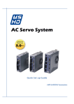
1
AC Servo System
Frequency
Response
3.0kHz
User Manual
Rev. 1.0
AMP & MOONS’ Automation
MSHD User Manual
Important Notice
All rights reserved. No part of this work may be reproduced or transmitted in any form or by any
means without prior written permission of .
Disclaimer
The information in this manual was accurate and reliable at the time of its release. MOONS’. reserves the right to change the specifications of the product described in this manual without notice
at any time.
Trademarks
All marks in this manual are the property of their respective owners.
Customer Service
is committed to delivering quality customer service and support for all our products. Our goal is to
provide our customers with the information and resources so that they are available, without delay,
if and when they are needed.
In order to serve in the most effective way, we recommend that you contact your local sales representative for order status and delivery information, product information and literature, and application and field technical assistance. If you are unable to contact your local sales representative for
any reason, please use the most relevant of the contact details below:
For technical support, contact:
[email protected]
Part Number
For ordering the MSHD, refer to the following diagram:
MSHD - 006 - 2A
AF
1 - XX
Custom specifications
(If applicable)
Analog Input
1- One Analog input, 16bit
2- Two Analog, 14bit
Series
Rating
Cont/Peak(A)
1D5 1.5/4.5
003 3.0/9.0
4D5 4.5/18.0
006 6.0/18.0
008 8.0/28.0
010 10.0/28.0
013 13.0/28.0
Rev. 1.0
4/10/2012
Interface Options
AP- Analog/Pulse RS-232
AF- Analog/Pulse Rs-232/CANopen®/USB
EC- EtherCAT
AC Power 200V
Single Phase 115VAC(-15%~10%)50/60Hz
Single Phase 230VAC(-15%~10%)50/60Hz
Three Phase 120-240 L-L VAC +10% -15% 50/60 Hz
2
MSHD User Manual
Contents
1 Introduction................................................................................. 8
1.1 Documentation....................................................................................8
1.1.1 About This Manual...................................................................................8
1.1.2 Documentation Set for MSHD.................................................................8
1.2 Safety..................................................................................................8
1.2.1 Safety Symbols.......................................................................................8
1.2.2 Safety Instructions...................................................................................9
1.3 Standards Compliance.....................................................................10
1.3.1 General Information...............................................................................10
1.3.2 CE Compliance.....................................................................................10
1.4 Unpacking.........................................................................................10
2 Product Description................................................................. 11
2.1 Overview........................................................................................... 11
2.1.1 General Description............................................................................... 11
2.1.2 Product Options..................................................................................... 11
2.2 Technical Specifications....................................................................12
2.2.1
2.2.2
2.2.3
2.2.4
2.2.5
2.2.6
2.2.7
Dimensions............................................................................................12
Mechanical and Electrical Specifications..............................................13
Control Specifications............................................................................19
Protective Functions and Environmental Specifications�����������������������20
Communication Specifications..............................................................20
I/O Specifications..................................................................................21
Motor Feedback Specifications.............................................................22
2.3 System Wiring - Pin Assignments.....................................................23
2.4 Controller Interface Wiring................................................................26
2.5 Machine Interface Wiring..................................................................26
3 Installation................................................................................. 27
3.1 Installation Overview.........................................................................27
3.2 Preparation.......................................................................................27
3.2.1 Hardware Requirements.......................................................................27
3.2.2 Computer System..................................................................................28
3.2.3 Servo System Wiring.............................................................................29
3.3 EMI Suppression..............................................................................31
3.3.1 CE Filtering Techniques........................................................................31
3.3.2 Grounding..............................................................................................32
3
Rev. 1.0
4/10/2012
MSHD User Manual
3.3.3
3.3.4
3.3.5
3.3.6
3.3.7
Shielding and Bonding..........................................................................32
Input Power Filtering.............................................................................32
Motor Line Filtering................................................................................33
I/O Signal Filtering.................................................................................33
Additional EMI Suppression Recommendations...................................33
3.4 Electrical System Considerations.....................................................34
3.4.1 Fusing....................................................................................................34
3.4.2 Leakage Current Considerations...........................................................34
3.4.3 Residual Current Protective Device (RCD)...........................................34
3.5 Mechanical Installation.....................................................................34
3.5.1 Mounting the MSHD..............................................................................34
3.5.2 Mounting Multiple Units.........................................................................35
3.6 Electrical Installation.........................................................................35
3.6.1
3.6.2
3.6.3
3.6.4
3.6.5
3.6.6
3.6.7
Connect Motor.......................................................................................36
Connect STO.........................................................................................36
Connect Regen.....................................................................................37
Connect Motor Feedback......................................................................39
Connect Controller I/Os.........................................................................40
Connect Machine I/Os...........................................................................42
Connect AC Input Voltage.....................................................................43
3.7 Set the Drive Address.......................................................................45
3.8 Connect to PC..................................................................................45
3.9 ServoStudio Software Installation.....................................................47
3.10 Power Up........................................................................................47
4 ServoStudio.............................................................................. 48
4.1 Overview...........................................................................................48
4.1.1 Interface Elements................................................................................49
4.1.2 Schematic Diagrams.............................................................................50
4.1.3 Parameter Values..................................................................................50
4.2 Dashboards......................................................................................51
4.2.1 Terminal.................................................................................................51
4.2.2 Scope....................................................................................................52
4.2.3 Expert....................................................................................................53
4.3 Wizards.............................................................................................57
4.3.1 Setup.....................................................................................................57
4.3.2 Tuning....................................................................................................57
4.4 Preferences......................................................................................57
Rev. 1.0
4/10/2012
4
MSHD User Manual
5 Configuration............................................................................ 59
5.1 Introduction.......................................................................................59
5.1.1 Configuration Parameters.....................................................................59
5.1.2 Managing Parameters...........................................................................59
5.1.3 Enabling the Drive.................................................................................61
5.2 Drive Configuration Sequence..........................................................62
5.3 Setup Wizard....................................................................................64
5.4 Connecting to the Drive............................................................................66
5.5 Drive Information..............................................................................67
5.6 Power Rating....................................................................................68
5.7 Motor.................................................................................................69
5.7.1 Motor Selection.....................................................................................69
5.7.2 Motor Parameters..................................................................................70
5.8 Motor Feedback................................................................................71
5.8.1
5.8.2
5.8.3
5.8.4
Incremental Encoder.............................................................................75
Sine Encoder.........................................................................................75
Resolver................................................................................................75
Encoder Simulation Output...................................................................76
5.9 Motion Units......................................................................................76
5.10 Current Limits.................................................................................76
5.10.1 Basic Current Limit..............................................................................76
5.10.2 Optional Analog Current Limit.............................................................77
5.11 Velocity Limits.................................................................................77
5.12 Foldback.........................................................................................79
5.12.1 Drive Foldback....................................................................................79
5.12.2 Motor Foldback....................................................................................80
5.13 Inputs and Outputs.........................................................................80
5.13.1 Digital I/Os...........................................................................................80
5.13.2 Analog I/Os..........................................................................................82
5.14 Enable/Disable................................................................................84
5.14.1 Drive Enable........................................................................................84
5.14.2 Clearing Faults....................................................................................85
5.14.3 Fault History........................................................................................85
5.15 Tuning Wizard.................................................................................85
6 Operation................................................................................... 88
6.1 Operation Modes..............................................................................88
5
Rev. 1.0
4/10/2012
MSHD User Manual
6.2
6.3
6.4
6.5
6.6
Analog Current Mode........................................................................89
Analog Velocity Mode.......................................................................90
Serial Current Mode..........................................................................91
Serial Velocity Mode.........................................................................92
Gear Mode........................................................................................93
6.6.1
6.6.2
6.6.3
6.6.4
Gearbox.................................................................................................93
Pulse and Direction Mode.....................................................................94
Master/Slave – Encoder Follower.........................................................94
Up/Down Counting................................................................................95
6.7 Serial Position Mode.........................................................................95
6.7.1 Motion Profile Information.....................................................................96
6.7.2 Relative Motion......................................................................................96
6.7.3 Absolute Motion.....................................................................................96
6.7.4
6.7.5
6.7.6
6.7.7
Position Error.........................................................................................96
In-Position Indication.............................................................................96
End of Motion........................................................................................96
Position Offset.......................................................................................97
6.8 Motor Direction.................................................................................97
6.9 Disable Mode....................................................................................97
6.9.1 Active Disable........................................................................................97
6.9.2 Dynamic Brake....................................................................................100
6.10
6.11
6.12
6.13
Motor Brake Control......................................................................101
Motor Phasing...............................................................................101
Motor Temperature Sensor...........................................................102
Tuning and Testing........................................................................103
6.13.1
6.13.2
6.13.3
6.13.4
Current Control Loop.........................................................................103
Velocity Control Loop........................................................................104
Linear Position Control Loop.............................................................104
Non-Linear Position Control Loop.....................................................105
6.14 Data Recording.............................................................................105
6.14.1
6.14.2
6.14.3
6.14.4
Recording Setup................................................................................106
Scope Toolbar...................................................................................108
[Motion|Terminal|Parameter Table|Measure] Panel........................... 110
Recording Data Using VarCom Instructions (Terminal)�������������������� 110
7 Firmware Upgrade.................................................................. 112
7.1 Preparation..................................................................................... 112
7.2 Ember Mode................................................................................... 112
Rev. 1.0
4/10/2012
6
MSHD User Manual
7.3 Upgrade Procedure........................................................................ 113
7.4 Resuming Operation....................................................................... 114
8 Troubleshooting..................................................................... 115
8.1 Faults and Warnings....................................................................... 115
8.2 Fault & Warning Indicators............................................................. 115
8.3 Drive Status 7-Segment Display..................................................... 116
9 Appendix: Scripting................................................................ 132
9.1 ServoStudio Scripts........................................................................132
9.2 Syntax and Special Characters......................................................132
9.3 Variables.........................................................................................132
9.4 Commands......................................................................................133
9.5 Sample Scripts................................................................................134
10 Appendix: MSHD Serial........................................................ 137
10.1 General Information......................................................................137
10.2 Data Transmission Format............................................................137
10.4 Variables and Commands.............................................................138
10.5 Data Control..................................................................................139
10.6 Message Format...........................................................................139
10.7 Asynchronous Error Messages.....................................................141
10.8 Examples of MSHD Serial Protocol...............................................141
11 Contacting MOONS’.............................................................. 146
7
Rev. 1.0
4/10/2012
MSHD User Manual
1 Introduction
1.1 Documentation
1.1.1 About This Manual
This manual describes the MSHD Servo Drive.
It provides the information required for installation, configuration and basic operation of the MSHD
unit.
This document is intended for persons who are qualified to transport, assemble, commission, and
maintain the equipment described herein.
1.1.2 Documentation Set for MSHD
This manual is part of a documentation set. The entire set consists of the
following:
• MSHD Quick Start Guide. Basic setup and operation of the drive.
• MSHD User Manual. Hardware installation, configuration and operation.
• MSHD VarCom Reference Manual. Parameters and commands used to program the MSHD.
1.2 Safety
Only qualified persons may perform the installation procedures. You do not need to be an expert
in motion control to install and operate the drive system. However, you must have a basic understanding of electronics, computers, mechanics, and safety practices.
The MSHD utilizes hazardous voltages.
Be sure the drive is properly grounded.
Before you install the MSHD, review the safety instructions in this manual.Failure to follow the
safety instructions may result in personal injury or equipment damage.
1.2.1 Safety Symbols
Safety symbols indicate a potential for personal injury or equipment damage if the recommended
precautions and safe operating practices are not followed.The following safety-alert symbols are
used on the drive and in the documentation:
Rev. 1.0
4/10/2012
Caution
ISO 7000-0434 (2004-01)
Warning.Dangerous voltage.
IEC 60417-5036 (2002-10)
Protective earth; protective ground
IEC 60417–5019 (2006-08)
Caution, hot surface
IEC 60417-5041 (2000-10)
8
MSHD User Manual
1.2.2 Safety Instructions
• Read all available product documentation before assembling and commissioning. Incorrect
handling of this product may cause personal injury and/or damage to equipment. Adhere
strictly to the installation instructions and requirements.
• All system components must be connected to ground. Electrical safety is provided through
a low-resistance earth ground connection. (Protective Class 1 according standard EN/IEC
618005-1.)
• This product contains static sensitive components that can be damaged by incorrect handling.
Avoid contact with high insulating materials (artificial fabrics, plastic film, etc.). Place the product on a conductive surface. Ground yourself (discharge any possible static electricity buildup) by touching an unpainted, metal, grounded surface.
• Keep all covers and cabinet doors shut during operation. Otherwise, potential hazards may
cause personal injury and/or damage to equipment.
• During operation the product has electrically charged components and hot surfaces. The heat
sink can reach temperatures of 90°C. Control and power cables can carry a high voltage,
even when the motor is not rotating.
• To avoid electric arcing and hazards to personnel and electric contacts, never disconnect or
connect the product while the power source is energized.
• After removing the power source from the equipment, wait at least 5 minutes before touching or disconnecting sections of the equipment that normally carry electrical charges (e.g.,
capacitors, contacts, screwed connections). For safety, measure the electrical contact points
with a meter before touching the equipment. Wait until the voltage drops below 30 VAC before
handling components.
• Provide a power mains disconnect device in according with local regulations.
• Before testing and setting up, the manufacturer of the machine must generate a hazard analysis for the machine, and take appropriate measures to ensure that unforeseen movements
cannot cause injury or damage to any person or property.
• Since the drive meets IP20, the end user must select an enclosure that permits safe operation
of the drive. The enclosure must meet at least IP54 made of metal or material with rating flammability of 5 VA.
• Since the leakage current to PE is greater than 3.5 mA, compliance with IEC61800-5-1 requires that either the PE connection be doubled or a connecting cable with a cross-section
greater than10 mm² be used. Use the PE terminal and the PE connection screws to meet this
requirement.
• Wiring of green color with or without one or more yellow stripes must not be used except for
protective bonding.
9
Rev. 1.0
4/10/2012
MSHD User Manual
1.3 Standards Compliance
1.3.1 General Information
The MSHD has been successfully tested and evaluated according to standards IEC 61800-5-1.
Conformance for UL 508C is in progress. This testing outlines the minimum requirements for electrically operated power conversion equipment (frequency converters and servo amplifiers), which
are intended to eliminate the risk of fire, electric shock, or injury to persons.
UL 508C references UL 840, which describes the achievement by design of air and insulation
creepage spacings for electrical equipment and printed circuit boards. The MSHD provides overload protection and current limit control.
The drive is intended for operation in pollution level 2 environment.
The terminals on the controller are coded so they can easily be identified in the instructions. The
instructions identify the connections for the power supply, load, control, and ground.
Integral solid state short circuit protection does not provide branch circuit protection. Branch circuit
protection must be provided in accordance with the National Electrical Code and any additional
local codes, or the equivalent.
1.3.2 CE Compliance
The MSHD is designed to comply with the following European directives. Formal certification is
pending.
•
EC Directive 2004/108/EC
Electromagnetic Compatibility
Standard EN 61800-3 (2004)
• LVD Directive 2006/95/EC
Electrical Safety: Low voltage directive
Standard IEC 61800-5-1 (2007)
1.4 Unpacking
The package contains the MSHD drive only.
1. Open the package and remove all packing materials.
2. Check to ensure there is no visible damage to the MSHD drive. If damage is detected, notify
the carrier immediately.
Rev. 1.0
4/10/2012
10
MSHD User Manual
2 Product Description
2.1 Overview
2.1.1 General Description
The MSHD is a full-featured, high-performance servo drive featuring innovative technologies and
industry-leading power density.
Key features of the MSHD include:
•
Support for rotary
•
Operation in current, velocity and position control loops.
•
Eleven digital inputs, six digital outputs, together with an analog input and output, to meet any
I/O requirement.
•
Various communication options.
•
Various motor feedback options.
•
Firmware customization to address special application requirements.
•
OEM motors predefined in user interface to enable immediate integration.
2.1.2 Product Options
The MSHD product line offers a number of options (as of January 2012):
•
200VAC rating.
•
Continuous current of 1.5, 3, 4.5,
•
6, 8 10 or 13 A rms for the 200 V models.
•
One 16-bit or two 14-bit analog inputs.
•
Various interface options, including analog voltage/pulse train and CANopen.
Refer to the part number diagram at the beginning of this manual for the various ordering options
for the MSHD drive.
The primary 200 V product models are shown in Figure 2-1:
Figure 2-1. MSHDProduct Models (200V)2.2 Technical Specifications
11
Rev. 1.0
4/10/2012
MSHD User Manual
2.2 Technical Specifications
2.2.1 Dimensions
The various models of the MSHD are housed in one of three frames. The exterior dimensions of
the MSHD are shown in Figure 2-2 Figure 2-3 and Figure 2-4.
2 Holes for
M4 of #8 Screws
164
152.4
173
150
143.7
43.2
Figure 2-2. MSHD-1D5/MSHD-003 Dimensions (in mm)
Note: MSHD-003 shown here; MSHD-1D5 does not have fan.
M4 2p1s
(for screws M4 UN #8)
150
173
164
167.5
48.5
Figure 2-3. MSHD-4D5/MSHD-006 Dimensions (in mm)
Φ4.5 for
Screw M4
or Imp,#8
170
195
182
185
60
Figure 2-4. MSHD-008/MSHD-010/MSHD-013 Dimensions (in mm)
Rev. 1.0
4/10/2012
12
MSHD User Manual
2.2.2 Mechanical and Electrical Specifications
Table 2-1. Mechanical & Electrical Specifications – MSHD-1D5/MSHD-003
Single and Three-Phase
200V
Specification
MSHD-1D5
MSHD-003
Ratings
Voltage (VAC Line-Line) Nominal ±10%
120/240
120/240
Line Frequency (Hz)
50/60
50/60
1 Phase
1 Phase
2.5
5
Line Fuses (FRN-R, LPN, or equivalent) (A)
10
10
Withstand Voltage (Primary to Earth)
1500 VAC
(2121 VDC)
1500 VAC
(2121 VDC)
Control Circuit Input Power
(L1C, L2C)
120 or 240 VAC
1 Phase
1 Phase
Logic Input Fuse (Time
Delay)
120 or 240 VAC (A)
0.5
0.5
STO (Safe Torque Off)
STO Power Supply (VDC)
24 ±10%
24 ±10%
STO Fuse (Time Delay)
120 or 240 VAC (A)
1.5
1.5
Continuous Output Current (A rms)
1.5
3
Continuous Output Current (A peak)
2.12
4.24
Peak Output Current (A rms) for 2
seconds
4.5
9
Peak Output Current (A peak) for 2 seconds
6.3
12.72
VA at 120 VAC
280
440
VA at 240 VAC
370
740
PWM Frequency (kHz)
16
16
Max. Surge Soft Start Current (A)
7
7
Max. Charge Time (ms)
350
350
5
5
120/240 VAC
Input Power Circuit (L1, L2) Continuous Current ( 1ph A rms)
Motor Output (U, V, W)
Soft Start
Power Circuit Loss
W
Control Circuit Loss
W
Total Power Loss
W
Hardware
Unit Weight
kg
0.7
0.75
Connection Hardware
PE Ground Screw Size/Torque
M4/1.35 Nm
M4/1.35 Nm
Control Circuit (AWG) up to 3 meters
24-28
24-28
Main Circuit Motor Lines (AWG)
18
18
Main Circuit AC Inputs (AWG)
18
18
PE Ground Screw
4
4
Side-to-Side (mm)
15
15
Top/Bottom (mm)
50
50
Under-Voltage Trip (Nominal) (VDC)
100
100
Over-Voltage Trip (VDC)
420
420
Wire Size
Clearance Distance
Voltage Trip
13
Rev. 1.0
4/10/2012
MSHD User Manual
Single and Three-Phase
200V
Specification
MSHD-1D5
MSHD-003
Normally operates at quarter power; whentemperature exceeds high-speed fan trigger
temperature, operates at full power
No
Yes
Power Module Over-Temperature Fault
Regulated
±80
±80
Power Module Over-Temperature Fault
Non-regulated (°C)
±100
±100
Trigger Temperature for High Speed Fan
(°C)
NA
60
Peak Current (A)
6.3
12.7
Minimum Resistance (Ω)
64
31.5
W
Systemdependent
Systemdependent
Internal Bus Capacitance (μF)
380
380
Bus Voltage (Nominal) (VDC)
320
320
Bus Voltage (Nominal) 120 (VDC)
170
170
Bus Voltage (Nominal) 240 (VDC)
340
340
VHYS (Regen Circuit Turn Off) (VDC)
380
380
VMAX (Regen Circuit Turn On) (VDC)
400
400
Power Temperature
Fan
(°C)
Regen External
Regenerative Resistor
(B1+, B2)
External Shunt Regulator
Application Information
Rev. 1.0
4/10/2012
14
MSHD User Manual
Table 2-2. Mechanical & Electrical Specifications – MSHD-4D5/MSHD-006/MSDH-013
Single and Three-Phase
200V
Specification
MSHD-4D5
MSHD-006
Ratings
Input Power Circuit (L1,
L2, L3)
Voltage (VAC Line-Line) Nominal ±10%
120/240
120/240
Line Frequency (Hz)
50/60
50/60
120 VAC
1 Phase or
3 Phase
1 Phase or
3 Phase
240 VAC
1 Phase
1 Phase
Continuous Current (1 ph/3 ph A)
10/7
Line Fuses (FRN-R, LPN, or equivalent)
15
15
Withstand Voltage (Primary to Earth)
1500 VAC
(2121 VDC)
1500 VAC
(2121 VDC)
Control Circuit Input Power
120 or 240 VAC
(L1C, L2C)
1 Phase
1 Phase
Logic Input Fuse (Time
Delay)
120 or 240 VAC (A)
0.5
0.5
STO (Safe Torque Off)
STO Power Supply (VDC)
24 ±10%
24 ±10%
STO Fuse (Time Delay)
120 or 240 VAC (A)
1.5
1.5
Continuous Output Current (A rms)
4.5
6
Continuous Output Current (A peak)
6.63
8.48
18
18
Motor Output (U, V, W)
Soft Start
Peak Output Current (A rms) for 2
onds
sec-
Peak Output Current (A peak) for 2 seconds 25.45
25.45
VA at 120 VAC
900
VA at 240 VAC
1300
PWM Frequency (kHz)
16
16
Max. Surge Soft Start Current (A)
7
7
Max. Charge Time (ms)
250
250
5
5
Power Circuit Loss
W
Control Circuit Loss
W
Total Power Loss
W
Hardware
Unit Weight
kg
0.97
0.97
Connection Hardware
PE Ground Screw Size/Torque
M4/1.35 Nm
M4/1.35 Nm
Control Circuit (AWG) up to 3 meters
24-28
24-28
Main Circuit Motor Lines (AWG)
16
16
Main Circuit AC Inputs (AWG)
16
16
PE Ground Screw
4
4
Side-to-Side (mm)
15
15
Top/Bottom (mm)
50
50
Under-Voltage Trip (Nominal) (VDC)
100
100
Over-Voltage Trip (VDC)
420
420
Wire Size
Clearance Distance
Voltage Trip
15
Rev. 1.0
4/10/2012
MSHD User Manual
Power Temperature
Fan
Normally operates at quarter power; when
temperature exceeds high-speed fan trigger
temperature, operates at full power
No
Yes
Power Module Over-Temperature Fault
Regulated (°C)
±80
±80
Power Module Over-Temperature Fault
Non-regulated (°C)
±100
±100
Trigger Temperature for High Speed Fan
(°C)
60
60
Peak Current (A)
25.5
25.5
Minimum Resistance (Ω)
16
16
W
Systemdependent
Systemdependent
Internal Bus Capacitance (μF)
1120
1120
Bus Voltage (Nominal) (VDC)
320
320
VHYS (Regen Circuit Turn Off) (VDC)
380
380
VMAX (Regen Circuit Turn On) (VDC)
400
400
Power Module Over-Temperature Fault (°C)
Regen External
Regenerative Resistor
(B1+, B2)
External Shunt Regulator
Application Information
Rev. 1.0
4/10/2012
16
MSHD User Manual
Table 2-3 Mechanical & Electrical Specifications - MSHD-008/MSHD-010/MSHD-013
Single and Three-Phase
200V
Specification
MSHD-008 MSHD-010 MSHD-013
Voltage (VAC Line Line) Nominal ±10%
120/240
120/240
120/240
Line Frequency (Hz)
50/60
50/60
50/60
120/240 VAC
3 Phase
3 Phase
3 Phase
Ratings
Input Power Circuit
(L1, L2, L3)
Continuous Current (1 ph/3 ph A)
16/10.6
Line Fuses (FRN-R, LPN, or equivalent) 20
20
20
Withstand Voltage (Primary to Earth)
1500 VAC
(2121 VDC)
1500 VAC
(2121 VDC)
1500 VAC
(2121 VDC)
Control Circuit Input Power 120 or 240 VAC
(L1C, L2C)
1 Phase
1 Phase
1 Phase
Logic Input Fuse
(Time Delay)
120 or 240 VAC (A)
0.5
0.5
0.5
STO (Safe Torque Off)
STO Power supply (VDC)
24 ±10%
24 ±10%
24 ±10%
STO Fuse (Time Delay)
120 or 240 VAC (A)
1.5
1.5
1.5
Motor Output (U, V, W)
Continuous Output Current (A rms)
8
10
13
Continuous Output Current (A peak)
11.31
14.14
18.38
Peak Output Current (A rms) for
2 seconds
28
28
28
Peak Output Current (A peak) for
2 seconds
39.56
39.56
39.56
Soft Start
VA at 120 VAC
1700
VA at 240 VAC
2800
PWM Frequency (kHz)
8
8
8
Max. Surge Soft Start Current (A)
15
15
15
Max. Charge Time (ms)
350
350
350
5
5
5
Power Circuit Loss
W
Control Circuit Loss
W
Total Power Loss
W
Hardware
Unit Weight
kg
1.15
1.15
1.15
Connection Hardware
PE Ground Screw Size/Torque
M4/
1.35 Nm
M4/
1.35 Nm
M4/
1.35 Nm
Wire Size
Control Circuit (AWG) up to 3 meters
24-28
24-28
24-28
Main Circuit Motor Lines (AWG)
14
14
14
Main Circuit AC Inputs (AWG)
14
14
14
PE Ground Screw
4
4
4
Side-to-Side (mm)
15
15
15
Top/Bottom (mm)
50
50
50
Under-Voltage Trip (nominal) (VDC)
100
100
100
Over-Voltage Trip (VDC)
420
420
420
Clearance Distance
Voltage Trip
17
Rev. 1.0
4/10/2012
MSHD User Manual
Power Temperature
Fan
Normally operates at quarter power;
when temperature exceeds high-speed
fan trigger temperature, operates at full
power
Yes
Yes
Yes
Power Module Over-Temperature Fault
Regulated (°C)
±80
±80
±80
Power Module Over-Temperature Fault
Non regulated (°C)
±100
±100
±100
Power Module Over-Temperature Fault
(°C)
100
100
100
Trigger Temperature for High Speed
Fan (°C)
60
60
60
Peak current (A)
40
40
40
Minimum resistance (Ω)
10
10
10
W
Systemdependent
Systemdependent
Systemdependent
Internal Bus Capacitance (µF)
2110
2110
2110
Bus Voltage (Nominal) (VDC)
320
320
320
VHYS (Regen Circuit Turn Off) (VDC)
380
380
380
VMAX (Regen Circuit Turn On) (VDC)
400
400
400
Regen External Regenerative Resistor (B1+, B2)
External Shunt Regulator
Application Information
Rev. 1.0
4/10/2012
18
MSHD User Manual
2.2.3 Control Specifications
Table 2-4.Control Specifications – All 200 VAC Models
Feature
Motors
Operation Mode
Specification
Rotary servomotors
Auto-configuration
Automatic self-configuration of motor phasing and wire settings
Selectable Modes
Serial or analog current (torque), Serial or analog velocity,
serial or Pulse and Direction position
Input/Output
Current command / 3 phase PWM command
Performance
Update rate 31.25 μs (32 kHz), Output waveform sinusoidal
Current (Torque) Step Response Time
Control
Control Loop
Actual current reaches command in two cycles, 62.5 μs
DQ, PI, Feed-forward
Reference Command
Analog ±10 VDC, Serial, CANopen
Autotuning
Automatic self-tuning of current control loop parameters
Input/Output
Velocity command / Current command
Performance
Update rate 125 μs (8 kHz)
Selectable Velocity
Control Loops
PI , PDFF, Standard pole placement, Advance pole placement, Standard pole placement high frequency, Pole placement with active dumping
Filters
First order low pass filter, Double first low pass filter, Notch,
High pass filter, Band pass filter, User defined polynominal
filter
Reference Command
Analog ±10 VDC, Serial, CANopen
Input/Output
Position command / Velocity command
Performance
Update rate 250 μs (4 kHz)
Control loop
PID and feed-forward
Reference Command
Pulse and direction, Serial, CANopen
Input/Output
Position command or Velocity command/Current command
Performance
Update rate 250 μS (4 kHz)
Control Loop
Non-linear control algorithm provides very low tracking error, zero or minimum settling time and smooth movement;
includes an adaptive feed-forward feature that is applied at
end of movement end to achieve zero or minimum settling
time.
Filters
One second order low pass, two notch, and other filters to
handle flexible and resonant systems
Reference Command
Velocity command: Analog ±10 VDC, Serial, CANopen
Position command: Pulse and direction, Serial, CANopen
Autotuning
Automatic inertia load measurement, self-tuning and optimization of HD control loop parameters. Optimal settling time
up to 0-2 ms
Brake
Method
Control stops: Dynamic brake, Active disable
Display
Method
7-segment LED (green), display drive status
User Interface
ServoStudio Windows-based application
Function
Setting connection, Drive info, Power display, Motor, Feedback, I/O selection/configuration, Motion setting/tuning,
Fault history/display, Setup wizard, Expert view
Position
Revolutions, Counts, Degrees, User-defined
Velocity
rps, rpm, deg/s, user/s
Velocity Control
Position Control
HD Control
GUI
Rotary Units
Acceleration/Deceleration rps/s, rpm/s, deg/s2, user/s2
19
Rev. 1.0
4/10/2012
MSHD User Manual
2.2.4 Protective Functions and Environmental Specifications
Table 2-5. Protective Functions and Environmental Spec. – All 200 VAC Models
Feature
Specification
Protective Functions
Under- and over-voltage, Over-current, Drive and motor over-temperature,
Foldback, Feedback lost, Safety function (STO)
UL - UL508c (compliance testing in progress)
CE - EMC Directive 2004/108/EC, standard IEC61800-3,
Compliance Standard
CE Low Voltage Directive 73/23/EEC IEC61800-5-1
STO - Safe Torque Off (compliance testing in progress)
RoHS
Ambient temperature: Operation 0-45°C, Storage 0-70°C
Environment
Humidity: 10-90%
Altitude: < 1000m. If >1000m, derate 5% per 330m
Vibration: 0.5g
Protection class/ Pollution degree
Protection class: IP20, pollution degree: 2 as per IEC 60664-1
Do not use in the following locations: corrosive or flammable gasses, water oil or
chemical, dust including iron dust and salts
Configuration
Book mounting
2.2.5 Communication Specifications
Table 2-6. Communication Specifications – All 200 VAC Models
Feature
Specification
CAN*
CANopen – CiA 301 application layer and the CiA 402 device profile for drives
and motion control
Baud rate 0.5M 1M bit/s
RS232
ASCII-based, ServoStudio, HyperTerminal
Baud rate 9600 to 115200 bit/s
Maximum cable length 10 m
USB*
ASCII-based, ServoStudio, HyperTerminal
Baud rate 9600 to 115200 bit/s
Maximum cable length 3 m
Daisy Chain
Up to 8 axes
Axis address setting from 0-99 using two rotary switches
Maximum cable length 10 m
*Some features are not available on all models. Check the ordering options at the front of the
manual, or contact your supplier.
Rev. 1.0
4/10/2012
20
MSHD User Manual
2.2.6 I/O Specifications
Table 2-7. I/O Specifications – All 200 VAC Models
Feature
Specification
First Analog Input
Voltage Range
Analog ±10 VDC differential
Input Resolution
16 bit (14-bit on version with two analog inputs)
Input Impedance
8 kΩ (when using two analog inputs 20k Ω.)
Voltage Range
Analog ±10 VDC differential 14 bit
Input Resolution
14 bit
Input Impedance
20 kΩ
Equivalent Encoder Output
Signal
A-quad-B and marker differential, RS 422 line
transmitter
8x Digital Inputs
Signal
Configurable opto-isolated (compatible with sinking output)
Voltage
24 V
Max. Input Current
10 mA
Propagation Delay
Time
1 ms
Signal
Configurable opto-isolated (compatible with sinking output)
Voltage
24 V
Max Input Current
10 mA
Propagation Delay
Time
1 µs
Signal
Configurable open collector, opto-isolated sinking output
Voltage
24 V
Max. Current
40 mA
Propagation Delay
Time
1 ms
Signal
Configurable open collector, opto-isolated sinking output
Voltage
24 V
Max current
10 mA
Propagation Delay
Time
1 µs
Signal
Configurable analog output
Voltage Range
0-10 V
Resolution
8 bit
Max. Load
1 kΩ
Signal
A-quad-B and marker differential, RS 422 line
receiver
Max. Input frequency
3 MHz (before A-quad-B)
Functions
Dual loop, Master/Slave or Handwheel
Signal
Configurable dry contacts
Voltage
24V
Max. Current
1A
Second Analog Input
(optional)
3x Fast Digital Inputs
4x Digital Output *
2x Fast Digital Output
Analog Output
Secondary Feedback
Fault Output Relay
21
Rev. 1.0
4/10/2012
MSHD User Manual
2.2.7 Motor Feedback Specifications
Table 2-8. Motor Feedback Specifications – All 200 VAC Models
Motor Feedback
Specification
Supply Voltage from Drive
5 VDC (7 VDC*)
Max. Supply Current from Drive
250 mA
Max. Cable Length
AWG 28 – 3 m
AWG 2 – 10 m
Velocity estimation
Improved algorithm for velocity measurements
Signal
A-quad-B with or without marker/Halls, 8
channel Tamagawa, RS 422 or RS485 line
receiver, Differential
Max Input Frequency
3 MHz (before quadrature)
Signal
Open collector single-ended
Signal
Sine/cosine differential
Transformation Ratio
0.45-1.6
Resolver
Excitation Frequency
8 kHz
(Please contact us
for more information)
Input Voltage from Drive
6-22 Vpp
Max. DC Resistance
120 Ω (stator)
Max. Drive Current
55 mA rms
Output Voltage to Drive
10 Vpp
Signal
Sine/Cosine differential, with or without
Halls
Signal Level
1 Vpp @ 2.5 V
Max. Input Frequency
270 kHz
Protocols
EnDat® 2.1, Hiperface®
Input Impedance
120 Ω
General
Incremental Encoder
Hall Sensor
Sine Encoder
(Please contact us
for more information)
Maximum Drive Internal Interpolation 4096
SSI Encoder
(Please contact us
for more information)
Motor Temperature
Signal
Differential data and clock for synchronous
encoders
Data only for asynchronous encoders
Protocols
EnDat 2.2, BiSS-C, other SSI
Signal
Thermal resistor PTC or NTC, User-defined
fault threshold
* Some features are not available on all models. Check the ordering options at the front of the
manual, or contact your supplier.
Rev. 1.0
4/10/2012
22
MSHD User Manual
2.3 System Wiring - Pin Assignments
For more information, refer to the section Electrical Installation.
Daisy Chain
C8:10 PIN
RS232
C7: 4p4c
1
2
3
4
1
19
18
36
0.1" IDC Female
NELTRON 4401-10SR OR
COXOC 304A-10PSAAA03
(STX PN CONr00000010-67
Rx
GND ISO
TX
STO
Safe Torque OFF
P1: Molex
4
(JMP to #1)
3
(JMP to #2)
2
24V RTN
1
24V STO
Mating Connector type Crimp
Housing PN 436450400
(STX PN CONr1000004-09)
4x Crimp PN 0430300001
(STX PN PINr43030000-00)
Motor
P2: JST J300
1 PE Protective Earth
2 U
U Phase
3 V
V Phase
4 W
W Phase
Mating Connector type Crimp
Housing PN F32FSS-04V-KX
(STX PN CONr10000004-13)
4x Crimp PN SF3F-71GF-P2.0
(STX PN PINrSF3F71GF-00)
Controller I/F
C2: MDR 36 Plug
1
Return user supplied 24 VDC
19
User supplied 24V
2
OUT 1
20
IN 2
3
IN 1
21
4
Equivalent encoder output A22
Equivalent encoder output A+
5
Equivalent encoder output B23
Equivalent encoder output B+
6
Equivalent encoder output Z24
Equivalent encoder output Z+
7
25
Ground
8
ANIN 1 +
26
ANIN 1 9
Direction input +
27
Direction input 10
Ground
28
Pulse input +
11
Pulse input 29
Ground
12
30
13
Ground
31
IN 3
14
IN 4
32
IN 5
15
IN 6
33
OUT 2
16
OUT 3
34
**AX417
**AX4+
35
*ANIN 2 18
*ANIN 2 +
36
ANOUT
Mating Connector type Solder
3M solder Plug connector
PN 10136-3000PE
(STX PN CONr0000036-01)
3M solder plug Junction shell
PN 10336-52F0-008
(STX PN HODr00000036-00)
Mating Cable
(STX PN CBLrxM900036-00
x –1,2,3 meter)
1
Machine I/F
C3: MDR 20 Plug
11
Mating Connector type Spring
PN 04JFAT-SBXGF-I
10
Feedback
C4: MDR 26 Plug
AC Input and
Regeneration
P3: JST J300
1
2
3
4
5
6
B1+
B2
L1
L2
L1C
L2C
DC BUS +
Regen BUS AC Phase 1
AC Phase 2
Logic AC Phase 1
Logic AC Phase 2
Mating Connector type Crimp
Housing PN F32FSS-06V-KX
(STX PN CONr10000006-91)
5x Crimp PN SF3F-71GF-P2.0
(STX PN PINrSF3F71GF-00)
Mating Connector type Spring
PN 06JFAT-SBXGF-I
20
PE
Protective Ground
Terminal M4
* Optional, check ordering information
** Manufacturing setting
STX- MOONS’
1
14
13
26
1
Secondary encoder A+
11
Secondary encoder A-
2
Secondary encoder B+
12
Secondary encoder B-
3
Secondary encoder Z+
13
Secondary encoder Z-
4
Secondary encoder 5V
1 Incremental encoder A+
14 Incremental encoder A2 Incremental encoder B+
15 Incremental encoder B3 Incremental encoder Z+
16 Incremental encoder Z4 Hall U+
17 Hall V+
5 Hall W+
11 5V supply
24 Ground
12 Motor Temperature sensor
25 Motor Temperature sensor
13 5V supply
26 Shield
Mating Connector type Solder
3M solder Plug connector
PN 10126-3000PE
(STX PN CONr0000026-31)
3M solder plug Junction shell
PN 10326-52F0-008
(STX PN HODr00000026-00)
18 OUT 6
9 User supplied 24V
19 Return user supplied 24 VDC
10 Fault Relay 1
20 Fault Relay 2
Mating Connector type Solder
3M solder Plug connector
PN 10120-3000PE
(STX PN CONr0000020-28)
3M solder plug Junction shell
PN 10320-52F0-008
(STX PN HODr00000020-00)
Mating Cable
(STX PN CBLrxM900026-00
x –1,2,3 meter)
Mating Cable
(STX PN CBLrxM900020-00
x –1,2,3 meter)
14
Secondary encoder GND
5
IN 7
15
IN 8
6
IN 9
16
IN 10
7
IN 11
17
OUT 4
8
OUT 5
Figure 2-5. Pin Assignments on MSHD-1D5/MSHD-003
23
Rev. 1.0
4/10/2012
MSHD User Manual
Daisy Chain
C8:10 PIN
RS232
C7: 4p4c
1
2
3
4
0.1" IDC Female
NELTRON 4401-10SR OR
COXOC 304A-10PSAAA03
(STX PN CONr00000010-67
Rx
GND ISO
TX
1
19
18
36
USB
C1: Mini-B
STO
Safe Torque OFF
P1: Molex
4
(JMP to #1)
3
(JMP to #2)
2
24V RTN
1
24V STO
Mating Connector type Crimp
Housing PN 436450400
(STX PN CONr1000004-09)
4x Crimp PN 0430300001
(STX PN PINr43030000-00)
Motor
P2: JST J300
1 PE Protective Earth
2 U
U Phase
3 V
V Phase
4 W
W Phase
Mating Connector type Crimp
Housing PN F32FSS-04V-KX
(STX PN CONr10000004-13)
4x Crimp PN SF3F-71GF-P2.0
(STX PN PINrSF3F71GF-00)
Mating Connector type Spring
PN 04JFAT-SBXGF-I
(STX PN CONr10000004-19)
1
Return user supplied 24 VDC
19
User supplied 24V
2
OUT 1
20
IN 2
3
IN 1
21
4
Equivalent encoder output A22
Equivalent encoder output A+
5
Equivalent encoder output B23
Equivalent encoder output B+
6
Equivalent encoder output Z24
Equivalent encoder output Z+
7
25
Ground
8
ANIN 1 +
26
ANIN 1 9
Direction input +
27
Direction input 10
Ground
28
Pulse input +
11
Pulse input 29
Ground
12
30
13
Ground
31
IN 3
14
IN 4
32
IN 5
15
IN 6
33
OUT 2
16
OUT 3
34
**AX417
**AX4+
35
*ANIN 2 18
*ANIN 2 +
36
ANOUT
Mating Connector type Solder
3M solder Plug connector
PN 10136-3000PE
(STX PN CONr0000036-01)
3M solder plug Junction shell
PN 10336-52F0-008
(STX PN HODr00000036-00)
Mating Cable
(STX PN CBLrxM900036-00
x –1,2,3 meter)
Regeneration
P3: JST J300
1
1 B1+
DC BUS +
2 B2
Regen BUS Mating Connector type Crimp
Housing PN F32FSS-02V-KX
(STX PN CONr10000002-10)
2x Crimp PN SF3F-71GF-P2.0
(STX PN PINrSF3F71GF-00)
10
AC Input
P4: JST J300
1 L1
AC Phase 1
2 L2
AC Phase 2
3 L3
AC Phase 3
4 L1C Logic AC Phase 1
5 L2C Logic AC Phase 2
Mating Connector type Crimp
Housing PN F32FSS-05V-KX
(STX PN CONr10000005-03)
5x Crimp PN SF3F-71GF-P2.0
(STX PN PINrSF3F71GF-00)
1
14
13
26
PE
Protective Ground
Terminal M4
* Optional, check ordering information
** Manufacturing setting
STX- MOONS’
20
1 Incremental encoder A+
14 Incremental encoder A2 Incremental encoder B+
15 Incremental encoder B3 Incremental encoder Z+
16 Incremental encoder Z4 Hall U+
17 Hall V+
5 Hall W+
11 5V supply
24 Ground
12 Motor Temperature sensor
25 Motor Temperature sensor
13 5V supply
26 Shield
Mating Connector type Solder
3M solder Plug connector
PN 10126-3000PE
(STX PN CONr0000026-31)
3M solder plug Junction shell
PN 10326-52F0-008
(STX PN HODr00000026-00)
Mating Cable
(STX PN CBLrxM900026-00
x –1,2,3 meter)
Figure 2-6. Pin Assignments on MSHD-4D5/MSHD-006
Rev. 1.0
4/10/2012
24
Machine I/F
C3: MDR 20 Plug
11
Feedback
C4: MDR 26 Plug
Mating Connector type Spring
Not Available
Mating Connector type Spring
PN 05JFAT-SBXGF-I
(STX PN CONr10000005-04)
Controller I/F
C2: MDR 36 Plug
1
Secondary encoder A+
11
Secondary encoder A-
2
Secondary encoder B+
12
Secondary encoder B-
3
Secondary encoder Z+
13
Secondary encoder Z-
4
Secondary encoder 5V
14
Secondary encoder GND
5
IN 7
15
IN 8
6
IN 9
16
IN 10
7
IN 11
17
OUT 4
8
OUT 5
18 OUT 6
9 User supplied 24V
19 Return user supplied 24 VDC
10 Fault Relay 1
20 Fault Relay 2
Mating Connector type Solder
3M solder Plug connector
PN 10120-3000PE
(STX PN CONr0000020-28)
3M solder plug Junction shell
PN 10320-52F0-008
(STX PN HODr00000020-00)
Mating Cable
(STX PN CBLrxM900020-00
x –1,2,3 meter)
MSHD User Manual
RS232
C7: 4p4c
1
2
3
4
Rx
GND ISO
TX
Daisy Chain
C8:10 PIN
1
19
18
36
0.1" IDC Female
NELTRON 4401-10SR OR
COXOC 304A-10PSAAA03
(STX PN CONr00000010-67
STO
Safe Torque OFF
P1: Molex
4
(JMP to #1)
3
(JMP to #2)
2
24V RTN
1
24V STO
Mating Connector type Crimp
Housing PN 436450400
(STX PN CONr1000004-09)
4x Crimp PN 0430300001
(STX PN PINr43030000-00)
Motor
P2: JST J400
1
2
3
4
PE
U
V
W
Protective Earth
U Phase
V Phase
W Phase
Mating Connector type Crimp
Housing PN J43FSS-04V-KX
(STX PN CONr10000004-18)
4x Crimp PN SJ4F-71GF-M3.0
(STX PN CRPrSJ4F71GF-00)
Regeneration
P3: JST J400
1
2
B1+
B2
DC BUS +
Regen BUS 1
10
Feedback
C4: MDR 26 Plug
Main AC Input
P4: JST J400
L1
L2
L3
AC Phase 1
AC Phase 2
AC Phase 3
Mating Connector type Crimp
Housing PN J43FSS-03V-KX
(STX PN CONr10000003-19 )
3x Crimp PN SJ4F-71GF-M3.0
(STX PN CRPrSJ4F71GF-00 )
Logic powerAC Input
P5: JST J300
1
2
L1C
L2C
1
Return user supplied 24 VDC
19
User supplied 24V
2
OUT 1
20
IN 2
3
IN 1
21
4
Equivalent encoder output A22
Equivalent encoder output A+
5
Equivalent encoder output B23
Equivalent encoder output B+
6
Equivalent encoder output Z24
Equivalent encoder output Z+
7
25
Ground
8
ANIN 1 +
26
ANIN 1 9
Direction input +
27
Direction input 10
Ground
28
Pulse input +
11
Pulse input 29
Ground
12
30
13
Ground
31
IN 3
14
IN 4
32
IN 5
15
IN 6
33
OUT 2
16
OUT 3
34
**AX417
**AX4+
35
*ANIN 2 18
*ANIN 2 +
36
ANOUT
Mating Connector type Solder
3M solder Plug connector
PN 10136-3000PE
(STX PN CONr0000036-01)
3M solder plug Junction shell
PN 10336-52F0-008
(STX PN HODr00000036-00)
Mating Cable
(STX PN CBLrxM900036-00
x –1,2,3 meter)
Mating Connector type Crimp
Housing PN J42FSC-02V-KX
(STX PN CONr10000002-14)
2x Crimp PN SJ4F-71GF-M3.0
(STX PN CRPrSJ4F71GF-00 )
1
2
3
Controller I/F
C2: MDR 36 Plug
Logic AC Phase 1
Logic AC Phase 2
Mating Connector type Crimp
Housing PN F32FSS-02V-KX
(STX PN CONr10000002-10)
2x Crimp PN SF3F-71GF-P2.0
(STX PN PINrSF3F71GF-00)
PE
Protective Ground
Terminal M4
1
14
13
26
* Optional, check ordering information
** Manufacturing setting
STX- MOONS’
Machine I/F
C3: MDR 20 Plug
11
20
1
Secondary encoder A+
11
Secondary encoder A-
2
Secondary encoder B+
12
Secondary encoder B-
3
Secondary encoder Z+
13
Secondary encoder Z-
4
Secondary encoder 5V
1 Incremental encoder A+
14 Incremental encoder A2 Incremental encoder B+
15 Incremental encoder B3 Incremental encoder Z+
16 Incremental encoder Z4 Hall U+
17 Hall V+
5 Hall W+
11 5V supply
24 Ground
12 Motor Temperature sensor
25 Motor Temperature sensor
13 5V supply
26 Shield
Mating Connector type Solder
3M solder Plug connector
PN 10126-3000PE
(STX PN CONr0000026-31)
3M solder plug Junction shell
PN 10326-52F0-008
(STX PN HODr00000026-00)
18 OUT 6
9 User supplied 24V
19 Return user supplied 24 VDC
10 Fault Relay 1
20 Fault Relay 2
Mating Connector type Solder
3M solder Plug connector
PN 10120-3000PE
(STX PN CONr0000020-28)
3M solder plug Junction shell
PN 10320-52F0-008
(STX PN HODr00000020-00)
Mating Cable
(STX PN CBLrxM900026-00
x –1,2,3 meter)
Mating Cable
(STX PN CBLrxM900020-00
x –1,2,3 meter)
14
Secondary encoder GND
5
IN 7
15
IN 8
6
IN 9
16
IN 10
7
IN 11
17
OUT 4
8
OUT 5
Figure 2-7. Pin Assignments on MSHD-008/MSHD-010/MSHD-013
25
Rev. 1.0
4/10/2012
MSHD User Manual
2.4 Controller Interface Wiring
Figure 2-8. Controller Interface Wiring Diagram
2.5 Machine Interface Wiring
Figure 2-9. Machine Interface Wiring Diagram3 Installation
Rev. 1.0
4/10/2012
26
MSHD User Manual
3 Installation
3.1 Installation Overview
Perform the following steps to install and setup a MSHD system.
1. Mount the MSHD.
2. Connect the motor to P2.
3. Connect safe torque off (STO) to P1, or use jumpers to bypass.
Refer to the section Connect STO.
4. Connect regen resistor to pins B1+ and B2 on P3, if required.
5. Connect motor feedback to C4.
6. Connect machine I/Os to C3 and/or controller I/Os at C2.
7. Connect AC input voltage.
Note: This interface varies among models.
Refer to the section Connect AC Input Voltage.
8. Set the drive address using the rotary switches.
9. Connect the drive to the PC.
10. Power up the drive and the PC.
11. Install ServoStudio software.
12. Using ServoStudio, configure and test the drive.
3.2 Preparation
3.2.1 Hardware Requirements
The following hardware is required for installation.
• Mating connectors and the associated crimp pins for interfaces P1, P2, P3, and P4 (all models) and P5 (only for MSHD-008, MSHD-010 and MSHD-013).
• Mating connectors for interfaces C2, C3 and C4:
• Connector C2 (Controller I/O):
Plug 3M 10136-3000PE and shell 3M 10336-52F0-008
• Connector C3 (Machine I/O):
Plug 3M 10120-3000PE and shell 3M 10320-52F0-008
• Connector C4 (Motor Feedback):
Plug 3M 10126-3000PE and shell 3M 10326-52F0-008
• Wires for connectors:
• Connector P1: 26–28 AWG for all models.
• Connectors P2, P3, and P4:
18 AWG – for MSHD-1D5 and MSHD-003
16 AWG – for MSHD-4D5 and MSHD-006
14 AWG – for MSHD-008, MSHD-010 and MSHD-013
27
Rev. 1.0
4/10/2012
MSHD User Manual
• Connector P5 (only for MSHD-008, MSHD-010 and MSHD-013): 16 AWG
• Connectors C2 (Controller I/O), C3 (Machine I/O) and C4 (Motor Feedback): 24–28
AWG.
• Crimping tools, if you are not using ready-made cable assemblies:
• Connector P1: Molex crimper 0638190000
• Connectors P2, P3, P4, P5: JST crimper YRF-1070.
If a crimp pin extraction tool is needed, use JST extraction tool EJ JFAJ3.
• M4 ring or spade terminal.
• A small slotted screwdriver for setting the drive address switches.
• For connection to the host computer, use one of the following:
• USB 2.0 A to Mini-B cable (USB interface)
• 4p4c plug and cable (RS232 interface)
Crimping
Prior to crimping, strip 2 mm at the end of wire, as shown in Figure 3-1.
Figure 3-1. Stripped Wire in Crimp Pin
3.2.2 Computer System
The following computer system and software are required:
• 2 GHz CPU
• 1 MB RAM
• 1000 MB available on hard drive (after .net 4 is installed)
• USB port for connecting to the drive
• Operating system: Windows XP-SP3, or Windows 7
• ServoStudio, the graphical software interface for configuring and testing the drive. Download
from the MSHD product page on the website.
• .Net4 (for details, refer to .NET Framework System Requirements). If .NET 4 is not installed
on the computer, ServoStudio will guide you through the installation, but will not install it automatically.
Rev. 1.0
4/10/2012
28
MSHD User Manual
3.2.3 Servo System Wiring
Daisy Chain
RS232 Connection
optional connection to PC
Mains
Single-Phase
230VAC
Rotary switches
Drive addressing
Circuit Breaker
or Fuses
STO
Safe Torque Off
Connect to *24VDC
power supply OR use
bypass plug
Line Filter
(optional)
Connection to Host Controller
Connection to Additional IOs
5x digital inputs
3x digital outputs
1x fault relay
Secondary feedback
Motor Feedback
Magnetic
Contactor
*Regenerative resistor
(optional)
Voltage reference input
Pulse&Direction input
6x digital inputs
3x digital outputs
1x analog output
Ground
(Protective Earth)
Motor Power
Brake output
Motor brake
(optional)
*Relay
*24VDC power supply
Note: Refer to section EMI Suppression
in MSHD User Manual
*- To be supplied by customer
AC supply for the main power input(L1 L2) and for the logic power input(L1C L2C)
must be from the same AC phase input, as show in the diagram.
Figure 3-2. MSHD-1D5/MSHD-003 Servo System Wiring,
Using Single-Phase 230 VAC
29
Rev. 1.0
4/10/2012
MSHD User Manual
Daisy Chain
RS232 Connection
optional connection to PC
Mains
Single-Phase
230VAC
Rotary switches
Drive addressing
Circuit Breaker
or Fuses
STO
Safe Torque Off
Connect to *24VDC
power supply OR use
bypass plug
Line Filter
(optional)
Connection to Host Controller
*Regenerative resistor
(optional)
Magnetic
Contactor
Voltage reference input
Pulse&Direction input
6x digital inputs
3x digital outputs
1x analog output
Connection to Additional IOs
Ground
(Protective Earth)
Motor Power
Motor Feedback
5x digital inputs
3x digital outputs
1x fault relay
Secondary feedback
Brake output
Motor brake
(optional)
*Relay
*24VDC power supply
Note: Refer to section EMI Suppression
in MSHD User Manual
*- To be supplied by customer
AC supply for the main power input(L1 L2) and for the logic power input(L1C L2C)
must be from the same AC phase input, as show in the diagram.
Figure 3-3. MSHD-4D5/MSHD-006 Servo System Wiring,
Using Single-Phase 230 VAC
Rev. 1.0
4/10/2012
30
MSHD User Manual
Mains
Single-Phase
230VAC
Daisy Chain
RS232 Connection
optional connection to PC
Rotary switches
Circuit Breaker
or Fuses
Drive addressing
STO
Line Filter
Safe Torque Off
Connect to *24VDC
power supply OR use
bypass plug
(optional)
Connection to Host Controller
*Regenerative resistor
(optional)
Magnetic
Contactor
Voltage reference input
Pulse&Direction input
6x digital inputs
3x digital outputs
1x analog output
Connection to Additional IOs
Ground
(Protective Earth)
Motor Power
Motor Feedback
5x digital inputs
3x digital outputs
1x fault relay
Secondary feedback
Brake output
Motor brake
(optional)
*Relay
*24VDC power supply
Note: Refer to section EMI Suppression
in MSHD User Manual
*- To be supplied by customer
AC supply for the main power input(L1 L2) and for the logic power input(L1C L2C)
must be from the same AC phase input, as show in the diagram.
Figure 3-4. MSHD-008/MSHD-010/MSHD-013 Servo System Wiring,
Using Three-Phase 230 VAC
3.3 EMI Suppression
3.3.1 CE Filtering Techniques
The MSHD drive complies with the CE standards specified in the section Standards Compliance.
Proper bonding, grounding and filtering techniques must be applied in order to meet this standard.
Noise currents often occur in two types. The first is conducted emissions that are passed through
ground loops. The quality of the system grounding scheme inversely determines the noise amplitudes in the lines. These conducted emissions are of a common-mode nature from line to neutral
(or ground). The second is radiated high-frequency emissions usually capacitively coupled from
line-to-line and are differential in nature.
To properly mount the EMI filters, the enclosure should have an unpainted metallic surface. This
allows for more surface area to be in contact with the filter housing and provides a lower impedance path between this housing and the back plane. The back panel, in turn, has a high frequency
ground strap connection to the enclosure frame or earth ground.
31
Rev. 1.0
4/10/2012
MSHD User Manual
3.3.2 Grounding
System grounding is essential for proper performance of the drive system.
The AC input voltage ground wire must be connected to the PE terminal, located on the MSHD
front panel. This is necessary for both safety and EMI reduction.
Use a single point ground for the system (start wiring) to avoid ground loops.
It is strongly recommended that the MSHD be mounted to a metallic back panel, and that a high
frequency ground be provided to connect the back panel to earth ground. Provide an electrical
connection across the entire back surface of the drive panel. Electrically-conductive panels such
as aluminum or galvanized steel are recommended. For painted and other coated metal panels,
remove all coating behind the drive. The objective is to provide an extremely low impedance path
between the filters, drives, power supplies, and earth ground for highfrequency signals that might
cause EMI. Use a flat braid or copper bus bar to achieve high-frequency grounding. When connecting high frequency grounds, use the shortest braid possible.
Ensure good connections between the cabinet components. Connect the back panel and cabinet
door to the cabinet body using several conductive braids. Never rely on hinges or mounting bolts
for ground connections. Ensure good ground connection from cabinet to proper earth ground.
Ground leads should be the same gauge as the leads to main power or one gauge smaller.
3.3.3 Shielding and Bonding
Motor and feedback cables must be shielded in order to minimize noise emissions and increase
the immunity levels of the drive system. The shield should be connected to ground at both ends.
The proper bonding of shielded cables to a grounded surface is imperative for minimizing noise
emissions and increasing immunity levels of the drive system. Its effect is to reduce the impedance between the cable shield and the back panel. It is recommended that all shielded cables be
bonded to the back panel.
The motor and feedback cables should have the shield exposed as close to the drive as possible.
This exposed shield is bonded to the back panel using either non-insulated metallic cable clamps
or cable bonding clamps.
It is recommended to use a star point shield connection, for example with a shielding busbar.
For cables entering a cabinet, connect shields on all 360° of the cable.
Lines between servo drives and filters and external brake resistor must be shielded.
3.3.4 Input Power Filtering
The MSHD electronic system components require EMI filtering in the input power leads to meet
the CE/EMC requirements for the industrial environment. This filtering blocks conducted type
emissions from exiting onto the power lines and provides a barrier for EMI on the power lines.
Care must be taken to adequately size the system. The type of filter is determined according to
the voltage and current rating of the system and whether the incoming line is single- or threephase. One input line filter can be used for multi-axis control applications.
Rev. 1.0
4/10/2012
32
MSHD User Manual
Implementation of the input power filter must adhere to the following guidelines:
• Maintain separation of leads entering and exiting the mains filter.
• Filter must be mounted on the same panel as the drive.
• Filter must be mounted as close as possible to the drive, to prevent noise from being capacitively coupled into other signal leads and cables..
• When mounting the filter to the panel, remove any paint or material covering. Use an unpainted metallic back panel, if possible.
• Filters are provided with a ground connection. All ground connections must be tied to ground.
• Filters can produce high leakage currents. Filters must be grounded before connecting the
supply!
• Filters should not be touched for 10 seconds after removing the supply.
3.3.5 Motor Line Filtering
Motor line filtering using ferrite cores might be necessary for CE compliance of MSHD systems.
This additional filtering can increase the reliability of the system. Poor non-metallic enclosure
surfaces and lengthy, unbonded (or unshielded) motor cables that couple noise line-to-line (differential) are just some of the factors that lead to the necessity of motor lead filtering.
Motor lead noise may be either common-mode or differential. The commonmode conducted currents occur between each motor lead and ground (line-toground). Differential radiated currents
exist from one motor lead to another (line-to-line). The filtering of the lines feeding the motor
provides additional attenuation of noise currents that enter surrounding cables and equipment I/O
ports in close proximity.
3.3.6 I/O Signal Filtering
I/O filtering may be desirable (depending on system installation, application, and integration with
other equipment). To avoid unwanted signals entering and disturbing the drive system or other associated equipment, place ferrite cores on I/O lines.
3.3.7 Additional EMI Suppression Recommendations
Route power and control cables separately. A distance of at least 200 mm is recommended, and
improves the interference immunity.
If input power and motor leads need to cross, make sure they cross at 90°.
Feedback lines may not be extended, since this would cause the shielding to be interrupted, and
possibly disturb the signal processing.
Splice cables properly. If you need to divide cables, use connectors with metal backshells. Make
sure that both shells connect along the full 360° of the shields. No portion of the cabling should be
unshielded. Never divide a cable across a terminal strip.
For differential inputs for analog signals, use twisted-pair, shielded signal lines, connecting shields
on both ends.
33
Rev. 1.0
4/10/2012
MSHD User Manual
3.4 Electrical System Considerations
3.4.1 Fusing
• US fuses: Class RK5 or CC or J or T, 600 VAC 200 kA, time-delay. The fuse must be UL and
CSA listed; UR-recognized is not sufficient.
• EU fuses: Types gRL or gL, 400 V/500 V, time-delay.
• Fuse holders: Standard fuse blocks, or finger-safe fuse holders according to IEC 60529. For
example:
• Bussmann: CH Series modular fuse holders, fuse size 0 to 30A, class J, 3 poles:
CH30J3
• Ferraz: Ultrasafe fuse holders, fuse size 0 to 30A, class J, 3 poles: US3J3I
3.4.2 Leakage Current Considerations
Leakage current via the PE conductor results from the combination of equipment and cable leakage currents. The leakage current frequency pattern comprises a number of frequencies, whereby
the residual-current circuit breakers definitively evaluate the 50 Hz current. For this reason, the
leakage current cannot be measured using a conventional multimeter.
As a rule of thumb, the following assumption can be made for leakage current on cables, depending on the PWM frequency of the output stage:
• Ileak = n x 20 mA + L x 1 mA/m at 8 kHz PWM frequency at the output stage
• Ileak = n x 20 mA + L x 2 mA/m at a 16 kHz PWM frequency at the outputstage
(where Ileak=leakage current, n=number of drives, L=length of motor cable)
Since the leakage current to PE is greater than 3.5 mA, compliance with IEC61800-5-1 requires
that either the PE connection be doubled or a connecting cable with a cross-section greater
than10 mm² be used. Use the PE terminal and the PE connection screws to meet this requirement.
3.4.3 Residual Current Protective Device (RCD)
In compliance with standards IEC 60364-4-41 Regulations for Installation and IEC 60204 Electrical Equipment of Machinery, residual current protective devices (RCD) can be used provided the
requisite regulations are met.
RCDs which are sensitive to all currents must be used in order to detect any DC fault current.
To protect against direct contact (with motor cables shorter than 5 m), it is recommended that each
drive be protected individually using a 30 mA RCD, which is sensitive to all currents.
3.5 Mechanical Installation
3.5.1 Mounting the MSHD
Using the bracket on the back of the MSHD, mount the MSHD on a grounded conductive metal
panel. The panel must be sufficiently rigid.
Rev. 1.0
4/10/2012
34
MSHD User Manual
3.5.2 Mounting Multiple Units
When multiple MSHD units are mounted side-by-side within a cabinet or enclosure, the recommended spacing is 10 mm. When mounting units top-tobottom, the recommended spacing is 50
mm for all models.
It is important to maintain an ambient temperature within the enclosure that does not exceed 45°C.
3.6 Electrical Installation
Figure 3-5. MSHD Front Panel Interfaces
35
Rev. 1.0
4/10/2012
MSHD User Manual
3.6.1 Connect Motor
Motor uses interface P2 on all MSHD models.
Connect the motor interface.
Figure 3-6.
Motor Interface
Table 3-1. Motor Interface
Pin
1
2
3
4
Pin Label
PE
U
V
W
Function
Protective ground (motor housing)
Motor Phase U
Motor Phase V
Motor Phase W
Table 3-2. Motor Interface Mating Connector
Item
Manufacturer
Housing and 4-pin
crimp
Spring
terminal
Wire Gauge
MSHD-1D5
MSHD-003
MSHD-4D5
MSHD-006
JST J300
F32FSS-04V-KX and
SF3F-71GF-P2.0
JST J300
F32FSS-04V-KX and
SF3F-71GF-P2.0
MSHD-008
MSHD-010
MSHD-013
JST J400
J43FSS-04V-KX and
SJ4F-71GF-M3.0
04JFAT-SBXGF-I
04JFAT-SBXGF-I
Not available
16 AWG
14-16 AWG
16 AWG
3.6.2 Connect STO
STO uses interface P1 on all MSHD models.
Safe torque off (STO) is a safety function that prevents the drive from delivering power to the motor, which can generate torque.
STO Enable and STO Return must be connected to enable MSHD operation. The
STO Enable signal voltage must be 24 VDC.
Connect the STO interface.
Rev. 1.0
4/10/2012
36
MSHD User Manual
Note: If the application does not require STO control, jumper pin 4 to pin 1,
and pin 3 to pin 2, to bypass the STO.
Figure 3-7. STO Interface
Table 3-3. STO Interface
Pin
1
2
Pin Label
24V
GND
3
4
Function
STO Enable
STO Return
24V Return, provided by the drive for use with emergency stop circuit
24V Supply, provided by the drive for use with emergency stop circuit
Table 3-4. STO Interface Mating Connector
Item
Manufacturer
Housing and
4-pin crimp
Spring terminal
Wire Gauge
All Models
Molex
436450400 and
43030-0006
Not available
26–28 AWG
3.6.3 Connect Regen
Regen uses interface P3 on all MSHD models.
Note: On models MSHD-1D5 and MSHD-003, Regen and AC Input Voltage are combined on one
connector.
If the application requires a regeneration (regen) resistor, use the P3 interface.
Connect the regen resistor between terminals B1+ and B2.
37
Rev. 1.0
4/10/2012
MSHD User Manual
Figure 3-8. Regen Interface
Table 3-5. Regen Interface
Pin
1
2
Pin Label
B1+
B2
Function
DC bus +
Regen bus -
Table 3-6. Regen Interface Mating Connector
Item
Manufacturer
Housing and 2-pin
crimp
Spring
terminal
Wire Gauge
JST J300
F32FSS-02V-KX and
SF3F-71GF-P2.0
MSHD-008
MSHD-010
MSHD-013
JST J400
J43FSS-02V-KX and
SJ4F-71GF-M3.0
Not available
Not available
14-16 AWG
14 AWG
MSHD-4D5
MSHD-006
Table 3-7. AC Input Voltage/Regen Interface Mating Connector
Item
Manufacturer
Housing and
4-pin crimp
Spring terminal
Wire Gauge
Rev. 1.0
4/10/2012
MSHD-1D5
MSHD-003
JST J300
F32FSS-06V-KX and
SF3F-71GF-P2.0
06JFAT-SBXGF-I
16 AWG
38
MSHD User Manual
3.6.4 Connect Motor Feedback
Connect Motor Feedback
Motor Feedback uses interface C4 on all MSHD models.
Wire the motor feedback interface according to the type of feedback device to be used in your application. Refer to the guidelines following the pinout table below.
Pins 1, 2, 14 and 15 have dual functionality.
Pins 11 and 13 for 5V to the encoder are used in digital board revision 0. Pin 18 can be used only
in digital board revision 1 and later.
Pin 25 for the motor temperature sensor is connected internally in the drive to MSHD ground.
Unused pins must remain unwired.
Figure 3-9.
1
14
13
26
Motor Feedback Interface
Table 3-8. Motor Feedback Interface
Pin
Function
Incremental encoder
A+
or SSI encoder data +
Incremental encoder
B+
or SSI encoder clock +
Incremental Encoder
Z+
Pin
Function
11
5V supply
12
Motor temperature sensor
13
5V supply
4
Hall U +
14
5
Hall W +
15
1
2
3
16
17
24
25
26
Incremental encoder A or SSI encoder data Incremental encoder B or SSI encoder clock Incremental encoder Z Hall V+
Ground
Motor temperature sensor
Shield
39
Rev. 1.0
4/10/2012
MSHD User Manual
Wiring Guidelines
• For incremental encoder with Halls, use pins 1, 14, 2, 15, 3, 16, 4, 17, 5, 11, 12, 24, 25, 26
3.6.5 Connect Controller I/Os
Controller I/Os uses interface C2 on all MSHD models.
Wire the digital and analog inputs and outputs according to the requirements of your application.
Wire the digital and analog inputs and outputs according to the requirements of your application.
Unused pins must remain unwired.
To preserve isolation of the digital I/Os, connect a 24 VDC source to pin 19. Connect the return of
the 24 VDC supply to pin 1, which functions as the ground path for the outputs.
Note: The 24 VDC supply and return can be connected on either the Controller interface (C2) or
the Machine interface (C3), but it is not necessary to connect it on both.
Figure 3-10.
1
19
18
36
Controller I/O Interface
Refer to the controller interface wiring diagram in Figure 2-8.
Rev. 1.0
4/10/2012
40
MSHD User Manual
Table 3-9. Controller I/O Interface
Pin
Function
Description
Pin
Function
Description
1
24 VDC
return
Return of the user-supplied
24 VDC
19
24 VDC
User supplied 24V, for I/O
biasing
2
Digital
output 1
Opto-isolated programmable
digital output. Read using OUT1
20
Digital
input 2
Opto-isolated programmable
digital input. Read using IN2
3
Digital
input 1
Opto-isolated programmable
digital input. Read using IN1
21
4
Equivalent
encoder
output A-
ALow side of the equivalent
encoder output signal (RS422)
22
5
Channel
B- out
Low side of the equivalent
23
encoder output signal B (RS422)
Channel
B+ out
High side of the equivalent
encoder output signal B
(RS422)
6
Channel
Z- out
Low side of the equivalent
encoder output index
(RS422)
24
Channel
Z+ out
High side of the equivalent
encoder output index (RS422)
7
Reserved for future use
25
Ground
Digital ground
8
Analog
input 1+
High side of the differential
analog command input
(±10 VDC)
26
Analog
input 1-
Low side of the differential
analog command input
(±10 VDC)
Direction
input+
High side of the direction signal
(RS422), or High side of the
master encoder signal B, or
High side of the down count
signal
27
Direction
input-
Low side of the direction
signal (RS422), or Low side of
the master encoder signal B, or
Low side of the down count
signal
High side of the pulse signal
(RS422), or High side of the
master encoder signal A, or
High side of the up count signal
Digital ground
9
Reserved for future use
Equivalent High side of the equivalent
encoder
encoder output signal A
output A+ (RS422)
10
Ground
Digital ground
28
Pulse
input+
11
Pulse
input-
Low side of the pulse signal
(RS422), or Low side of the
master encoder signal A, or
Low side of the up count signal
29
Ground
Reserved for future use
30
12
Reserved for future use
13
Ground
Digital ground
31
Digital
input 3
Opto-isolated programmable
digital input. Read using IN3
14
Digital
input 4
Opto-isolated programmable
digital input. Read using IN4
32
Digital
input 5
Fast opto-isolated
programmable digital input.
Read using IN5
15
Digital
input 6
Fast opto-isolated programmable digital input.
Read using IN6
33
Digital
output 2
Opto-isolated programmable
digital output. Read using OUT2
16
Digital
output 3
Fast opto-isolated programmable digital output. Read using
OUT3
34
Reserved for future use
35*
Analog
input 2-
Low side of the second
differential analog input
(±10 VDC)
High side of the second
differential analog input
(±10 VDC)
36
Analog
output
Analog output, referenced
to digital ground (0-10
VDC)
17
18*
Analog
input 2+
41
Reserved for future use
Rev. 1.0
4/10/2012
MSHD User Manual
3.6.6 Connect Machine I/Os
Machine I/Os uses interface C3 on all MSHD models.
Wire the machine inputs and outputs according to the requirements of your application.
Unused pins must remain unwired.
To preserve isolation of the digital I/Os, connect a 24 VDC source to pin 9. Connect the return of
the 24 VDC supply to pin 19, which functions as the ground path for the outputs.
Note: The 24 VDC supply and return can be connected on either the Controllerinterface (C2) or
the Machine interface (C3), but it is not necessary to connect it to both.
1
11
10
20
Figure 3-11. Machine I/O Interface
Refer to the machine interface wiring diagram in Figure 2-9.
Table 3-10. Machine I/O Interface
Pin
Function
1
Secondary High side of the secondary enencoder
coder input signal A (RS422), or
A+
High side of the pulse signal
2
Secondary High side of the Secondary enencoder
coder input signal B (RS422), or 12
B+
High side of the direction signal
Low side of the secondary enSecondary
coder input signal B (RS422),
encoder
or Low side of the direction
Bsignal
3
Secondary
High side of the secondary enencoder
coder input index (RS422)
Z+
13
Secondary Low side of the secondary enencoder Z- coder input index (RS422)
4
Secondary
5 VDC supply for the secondary
encoder
encoder
5V
14
Secondary Ground of the 5 VDC
encoder
supply for the secondary
ground
encoder.
5
Digital
input 7
Opto-isolated programmable
digital input. Read using IN7
15
Digital
input 8
Opto-isolated programmable
digital input. Read using IN8
6
Digital
input 9
Opto-isolated programmable
digital input. Read using IN9
16
Digital
input 10
Opto-isolated programmable
digital input. Read using IN10
7
Digital
input 11
Fast opto-isolated
programmable digital
input. Read using IN11
17
Digital
output 4
Opto-isolated programmable
digital output. Read using
OUT4
Rev. 1.0
4/10/2012
Description
42
Pin
Function
Description
11
Low side of the secondary enSecondary
coder input signal A (RS422),
encoder A
or Low side of the pulse、signal
MSHD User Manual
8
Digital
Opto-isolated programmable
18
digital output. Read using OUT5
Digital
output 6
Fast opto-isolated
programmable digital
output. Read using OUT6
9
output 5
User supplied 24V, for I/O
biasing
19
24 VDC
return
Return of the usersupplied
24 VDC
10
Fault relay
1
Terminal 1 of the dry contact
fault relay
20
Fault relay
2
Terminal 2 of the dry
contact fault relay
3.6.7 Connect AC Input Voltage
Note: The AC Input interfaces and connectors vary among MSHD models.
• MSHD-1D5 and MSHD-003: One connector for bus power and logic power uses interface P3.
• MSHD-006: One connector for bus power and logic power uses interface P4.
• MSHD-013: Two connectors – a connector for bus power uses interface P4, and another connector for logic power uses interface P5.
Make the following connections:
1. Connect L1, L2 and L3 (for bus power).
• If the main voltage is from a single-phase source, connect line and neutral to L1 and L2.
• If the main voltage is from a three-phase source, connect the phases to L1, L2 and L3.
2. Connect the AC input voltage ground wire to the PE terminal, located on the MSHD front panel.
Use an M4 ring or spade terminal.
Figure 3-12. Ground Terminals
3. Connect L1C and L2C (for logic power).
• If the main voltage is from a single-phase source, connect line and neutral to L1C
and L2C.
• If the main voltage is from a three-phase source, connect any two phases to L1C
and L2C.
Make sure the main voltage rating matches the drive specification. Applying incorrect
voltage may cause drive failure.
Make sure that the AC supply for the main power input (L1 and L2), and the logic power input (L1C and L2C) are from the same AC phase input, as shown in Figure 3-2.
Do not apply power until all hardware connections are complete.
Note: On models MSHD-1D5 and MSHD-003, Regen and AC Input Voltage are combined on one
connector. Since these models support only singlephase AC, they do not have a L3 terminal for
bus power.
43
Rev. 1.0
4/10/2012
MSHD User Manual
Table 3-11. AC Input Voltage
MSHD-1D5
MSHD-003
P3
MSHD-4D5
MSHD-006
P4
MSHD-008
MSHD-010
MSHD-013
P4
P5
Pin
Pin Label
Function
3
L1
AC Phase 1
4
L2
AC Phase 2
5
L1C
Logic AC Phase 1
6
LC2
Logic AC Neutral
Pin
Pin Label
Function
1
L1
AC Phase 1
2
L2
AC Phase 2
3
L3
AC Phase 3
4
L1C
Logic AC Phase 1
5
LC2
Logic AC Neutral
Pin
Pin Label
Function
1
L1
AC Phase 1
2
L2
AC Phase 2
3
L3
AC Phase 3
1
L1C
Logic AC Phase 1
2
LC2
Logic AC Neutral
Table 3-12. AC Input Voltage Interface Mating Connector
Item
MSHD-1D5/MSHD-003
Manufacturer
JST J300
Housing and 6-pin crimp
(includes Regen)
F32FSS-06V-KX andSF3F-71GF-P2.0
Spring terminal
06JFAT-SBXGF-I
Wire Gauge
16 AWG
MSHD-4D5/MSHD-006
Manufacturer
JST J300
Housing and 5-pin crimp
F32FSS-05V-KX and SF3F71-GF-P2.0
Spring terminal
05JFAT-SBXGF-I
Wire Gauge
14–16 AWG
MSHD-008/MSHD-010/ MSHD-013
Manufacturer
JST J400
Housing and 3-pin crimp
F32FSS-03V-KX and SJ4F-71GF-M3.0
Spring terminal
Not available
Wire Gauge
14 AWG
Manufacturer
JST J300
Housing and 2-pin crimp
F32FSS-02V-KX and SF3F-71GF-P2.0
Spring terminal
Not available
Wire Gauge
16 AWG
Rev. 1.0
4/10/2012
44
MSHD User Manual
3.7 Set the Drive Address
The MSHD has two 10-position rotary switches, accessible from the front of the unit. The switches
are used to set the drive address. When there is more than one drive on a daisy-chain or CANbus
network, each drive must have a unique address to enable its identification on the network.
Use the two rotary switches to set the drive address for both CAN and serial communication.
For Ethernet-based motion buses, the switch has no functional use for either the drive or the
network. It can be used at the application level to identify specific drives on a network.
Each switch has 10 positions:
• The upper switch positions are set as tens: 10, 20, 30 … 90
• The lower switch positions are set as ones: 0, 1, 2 … 9
Note: If two or more drives are connected to the network, address 0 cannot be used. A singular
drive may have the address 0.
Figure 3-13. Drive Address Rotary Switches
3.8 Connect to PC
To connect the drive to the host computer, use either one of the following interfaces:
• USB port. The interface is labeled C1 on all MSHD models. Use a USB 2.0 A to Mini-B cable.
Figure 3-14. USB Port
45
Rev. 1.0
4/10/2012
MSHD User Manual
The first time the drive is connected to the host computer on the USB port, Windows will detect the
device and display a Found New Hardware wizard.
Refer to the section Power Up.
• RS232 port. The interface is labeled C7 on all MSHD models.
Use a 4p4c plug.
Figure 3-15. RS232 Port
Table 3-13. RS232 Interface
Pin
Pin Label
Function
1
RX
Receive
2
GND ISO
Ground
3
TX
Transmit
4
Rev. 1.0
4/10/2012
Unused
46
MSHD User Manual
3.9 ServoStudio Software Installation
1. Install ServoStudio software on the host computer.
2. When installation is complete, start ServoStudio from the Windows Start menu or the shortcut
on your desktop.
3.10 Power Up
1. After completing the hardware connections, turn on power to the drive.
Note: If logic and bus AC supplies are separate, it is recommended that logic AC be turned on
before bus AC.
2. The first time the drive is connected to the host computer on the USB port, Windows detects
the device and displays a Found New Hardware wizard.
Browse to and select the Drivers folder. The path will vary, depending on the computer’s operating
system and the location selected for software installation; for example:
• \Program Files (x86)\\ServoStudio\Drivers
• \Program Files\\ServoStudio\Drivers
The wizard will automatically select and install the driver file STX-MSHD.inf from the
folder.
3. Look at the 7-segment display on the MSHD front panel.
Upon initial power up, the status display shows a flashing e, indicating a Parameter
Memory Checksum Failure. This fault will be cleared once the drive is configured and
the parameters are saved in the drive’s non-volatile memory.
Figure 3-16. 7-Segment LED Status Display
The digital display provides various indications of drive operation, such as operation modes, drive
enable status, and fault conditions.
For more information, refer to the section Drive Status 7-Segment Display.
47
Rev. 1.0
4/10/2012
MSHD User Manual
4 ServoStudio
4.1 Overview
ServoStudio is a graphic user interface (GUI) provided with the MSHD to enable setup, configuration and tuning of the drive.
ServoStudio allows you to program the drive parameters specifically for the motor to which the
MSHD is connected, and for the particular operation that the drive will be performing in the machine.
Figure 4-1. ServoStudio Software
ServoStudio provides two primary ways for setting up the MSHD servo drive.
• Using the Setup Wizard, which takes you step-by-step through the basic configuration process. The Tuning Wizard can be used after the basic configuration is completed, to tune the
non-linear position control loop.
• Using each setup screen individually, to access and define specific drive functions.
Rev. 1.0
4/10/2012
48
MSHD User Manual
4.1.1 Interface Elements
The ServoStudio application has four function areas:
Toolbar
Contains quick access buttons for frequently used functions.
Configuration – Triggers the internal drive configuration. The CONFIG command is required after certain variables are modified. Refer
to VarCom CONFIG. When the 7-digit display shows -1, CONFIG is
required.
Enable|Disable – Enables and disables the drive, and indicates the
state of the drive. Refer to the section Enabling the Drive. Refer also
to VarCom EN and VarCom K.
Offline|Online – Toggles the drive between online and offline states,
and indicates the state of the drive. Refer to the section Connecting
to the Drive.
Sidebar
Save – Saves the parameters currently displayed on screen to nonvolatile memory. Refer to the section Managing Parameters.
Contains a navigation menu to the various ServoStudio screens.
The sidebar can be hidden or displayed using the Arrow button.
49
Rev. 1.0
4/10/2012
MSHD User Manual
Task Screen
Displays various interactive screens for viewing, setting and testing
parameters and drive configurations.
These screens are described in detail in other sections throughout
this manual.
Status Bar
Displays the status of the drive.
• Progress bar. Some tasks may take more than a few seconds
to execute, such as connecting to the drive; if so, a green bar
shows the progress of the action.
• Faults. This segment of the status bar is green as long as no
faults exist; it is red whenever a fault exists. Click Faults to open
the Enable & Faults screen.
• Warnings. This segment of the status bar is green as long as
no warnings exist; it is yellow whenever a warning exists. Click
Warnings to open the Enable & Faults screen.
• Messages. Notifications from ServoStudio that do not require
immediate attention. They are saved and displayed upon request; you can continue normal work without viewing them. Click
Messages to see the full text.
For more information about warnings and faults, refer to the chapter
Troubleshooting.
4.1.2 Schematic Diagrams
ServoStudio uses schematic diagrams in many of the configuration and tuning screens to help
you visualize and correctly set values for required parameters.
Some of the fields in these screens are read-only. Their values are entered automatically according to the motor defined in the Motor screen and/or settings defined elsewhere in the software.
Other fields in these schematic screen are configurable (read/write). After entering or modifying a
value, press Enter to send the value to the drive. For more information about working with configurable fields, refer to the section Parameter Values.
Hover over a parameter field to view its description and VarCom equivalent.
4.1.3 Parameter Values
Throughout ServoStudio, you will work with fields containing configurable (read/write) drive parameters.
Whenever you begin entering a parameter value, the field turns blue.
Rev. 1.0
4/10/2012
50
MSHD User Manual
Once you press Enter, the value in the field is sent to drive.
• If the value entered is valid, the field reverts to white. The displayed format of the value might
be slightly different than what you entered; for example, if you enter 10, the drive might return
10.00.
• If the value entered is invalid, the field turns red.
Fields that are gray are read-only. Their values cannot be modified.
Press F1 when a parameter field is selected to open the Help file for the parameter.
4.2 Dashboards
ServoStudio has several dashboards. These screens contain a combination of function panes,
which allow you to work more efficiently.
4.2.1 Terminal
The Terminal screen allows you to send VarCom instructions to the drive, and read the drive’s
responses. It also includes a Watch panel that allows you to monitor parameters.
Figure 4-3. ServoStudio – Terminal Dashboard
ServoStudio provides two methods that reduce the need for command memorization and keyboard input:
• Autocompletion: An autocompletion system (IntelliSense) allows you to access commands
and descriptions of their functions. IntelliSense can be disabled in the Preferences screen.
When you begin typing a command, a list of available drive commands is displayed based on
the characters typed.
51
Rev. 1.0
4/10/2012
MSHD User Manual
• History: Use the Up arrow key to show a list of all command strings that have been sent to
drive in the present session (i.e., since ServoStudio was last opened).
When a command in the autocomplete or history list is highlighted:
• Press Enter to sends the command to drive.
• Press spacebar to edit the command. Right-click anywhere in the Terminal panel to access
two additional functions:
• Clear Terminal: Deletes the contents of the Terminal.
• Save to File: Prompts you to save the contents as a text file.
Watch Panel
The Watch panel is used to monitor drive variables. The rate at which variables are updated is
dependent on the load on the serial communications link and on the Refresh Rate of Data From
Drive setting in the Preferences screen.
All
Select or clear an individual checkbox to start or stop monitoring a specific
variable.
Click the header All to select or clear all variables listed.
Command
Use this field to enter the name of the drive variable whose value you want
to monitor. Click the header Command to sort the list alphabetically. Once
alphabetized, click the header to reverse ascending/ descending order.
Value
The value of the watched variable is displayed in this field.
Display Format
Select the format that is used for displaying the value: default, Binary Decimal or Hexadecimal.
Mask
Use this field to enter a value that will be logically ANDed with the parameter value.
4.2.2 Scope
The Scope screen enables you to configure recording settings, record data from the drive, and
display the data according to your preferences. It also allows you to generate motion in order to
record data related to that specific motion. Commands can be sent to the drive via the Terminal
tab.
Refer to the section Non-Linear Position Control Loop for detailed information.
Rev. 1.0
4/10/2012
52
MSHD User Manual
Figure 4-4. ServoStudio – Scope Dashboard
4.2.3 Expert
The Expert screen allows you to perform the following tasks:
• Send commands to the drive using the Terminal panel.
• Change operation mode and initiate motion using the Motion panel.
• Monitor parameters using the Watch panel.
• Set recording properties using the ScopeChart panel.
• Program and run scripts using the Script panel.
53
Rev. 1.0
4/10/2012
MSHD User Manual
Figure 4-5. ServoStudio – Expert Dashboard
The Expert toolbar has two additional buttons:
Restore – Resets the Expert screen to the default layout.
Return – Closes the Expert screen and reopens the standard ServoStudio interface. Alternately, use the X at the top right for the Return function.
The Expert screen has dockable panels, which can be visible, hidden or floating.
Click to autohide the panel to the edge of the screen. Small tab/s remain visible.
Hovering over the tabs opens the panel.
Indicates the panel is hidden. Click to keep the panel visible.
Double-click the top border of a panel to make it float. Double-click again to re-dock a floating
panel.
Alternately, click the top border of a panel and drag it to any location on the desktop. If a panel has
been dragged to a floating position, it must be dragged back into position. Clicking its top border
causes it to close.
To restore the default layout of panels in Expert Studio, use the Restore button on the Expert View
toolbar.
To save a personalized layout of panels in Expert Studio, do the following:
• From the ScopeChart toobar, open the Chart Options menu, or right-click anywhere in the
ScopeChart panel.
Rev. 1.0
4/10/2012
54
MSHD User Manual
• Select Windows Layout > Save Layout.
To load a saved personalized layout of panels in Expert Studio, do the following:
• From the ScopeChart toobar, open the Chart Options menu, or right-click anywhere in the
ScopeChart panel.
• Select Windows Layout > Load Layout.
[Terminal | Output] Panel
Terminal Tab
Refer to the section Terminal.
Output Tab
The Output tab shows data generated by the #Print command in a script.
Scope Panel
Refer to the section Data Recording.
[Watch | Motion | Measure] Panel
Watch Tab
Refer to the section Watch Panel.
Motion Tab
Refer to the section Operation Modes.
Measure Tab
Refer to the section Scope.
Script Panel
ServoStudio includes a simple scripting language that allows the MSHD to perform logical and
control tasks that can run independently. Such tasks include:
• Send commands to the drive.
• Read and set values in the drive.
• Define variables and perform simple operations on their values.
• Issue commands according to status or conditions.
• Control program flow.
• Plot recorded data
• Save and restore drive parameters.
The scripting language, commands and syntax are described fully in Appendix: Scripting.
Script Tab
Each script opens in its own tab. Any number of scripts can be open and in use.
The Script tab includes a toolbar with a number of buttons:
55
Rev. 1.0
4/10/2012
MSHD User Manual
Run – Validates and then runs a script.
Stop – Halts a running script.
Validate – Checks the syntax of a script to make sure all script commands are
valid. Highlights any errors. It does not check the validity of MSHD VarCom
instructions.
File – Click the arrow to access the file options:
• Open – Opens a saved script file. Also Ctrl+O
• Save – Saves the script to a file. Also Ctrl+S
• Save As – Saves the script under a different filename.
• Dump – Retrieves all parameters from drive memory. Can be used for
viewing and modifying parameter values, followed by Run to send new
values to drive. Refer to VarCom DUMP.
• Copy – Ctrl+C
• Paste – Same as Ctrl+V
• Clean Script – Selects and deletes all contents of script tab.
• Close Script – Closes script without saving contents.
Script file options can also be accessed by right-clicking anywhere in a Script
tab.
New Script – Opens a new tab for a new script.
ServoStudio provides two methods that reduce the need for command memorization and keyboard input:
• Autocompletion: An autocompletion system (IntelliSense) allows you to access commands
and descriptions of their functions. IntelliSense can be disabled in the Preferences screen.
When you begin typing a command, a list of available drive commands is displayed based on
the characters typed.
• History: Use the Up arrow key to show a list of all command strings that have been sent to
drive in the present session (i.e., since ServoStudio was last opened).
When a command in the autocomplete or history list is highlighted:
• Press Enter to sends the command to drive.
• Press spacebar to edit the command.
Rev. 1.0
4/10/2012
56
MSHD User Manual
4.3 Wizards
ServoStudio includes two wizards, or interactive utilities, that guide you through complex tasks.
4.3.1 Setup
The Setup Wizard takes you step-by-step through the most basic setup and configuration process.
Refer to the section Setup Wizard.
4.3.2 Tuning
The Tuning Wizard takes you through a procedure to autotune the various control loops.
Refer to the section Tuning Wizard.
4.4 Preferences
The Preferences screen allows you to modify file names and locations, runtime options, and other
ServoStudio default settings.
Figure 4-6. ServoStudio – Preferences Screen
57
Rev. 1.0
4/10/2012
MSHD User Manual
Startup
Configuration Files
Runtime Options
Default Screen – The task screen that is displayed when ServoStudio
is activated. It can be any of the screens listed in the sidebar. By default,
Drive Information is the default screen.
Show Splash Screen – Defines whether the ServoStudio splash screen
is displayed when ServoStudio is activated.
The names and locations of files used by ServoStudio. For Expert users
only.
Refresh Rate of Data from Drive – Sets the rate at which variable
values are refreshed on screen. This includes both user-defined watched
variables and system-defined variables which may trigger warnings or
faults. Defined in milliseconds. Refer to the section Watch Panel.
Turn On IntelliSense in Terminal: Activates autoselection and complete
when working in Terminal panel. Opens and displays list of available
drive commands that can be selected based on the characters entered.
Turn on IntelliSense in Script – Activates autoselection and complete
when working in Script panel. Opens and displays list of available drive
commands that can be selected based on the characters entered.
Auto Save options – For Expert users. Selected elements will be automatically saved and restored the next time ServoStudio is opened, even
if they were not explicitly saved before closing ServoStudio.
Project File
ServoStudio Version
Rev. 1.0
4/10/2012
Font Size – Defines the size of the text displayed in the Script and Terminal panels.
A project file contains all settings currently defined in ServoStudio, and
any autosaved data.
The version of the ServoStudio software.
58
MSHD User Manual
5 Configuration
5.1 Introduction
This section presents the main concepts and functions related to theconfiguration and operation of
the MSHD drive.
5.1.1 Configuration Parameters
Drive functionality is configured using various commands and variables, which are transmitted
over the communication bus. The terms variables and parameters are used interchangeably; drive
parameter set refers to the set of variables that are specifically defined for a particular application.
Commands and variables are identified by a mnemonic (VarCom) name. For example, MPOLES
is the mnemonic used to read and write the setting for the number of motor poles.
VarCom instructions, which are used with serial communications, are detailed in the MSHD
VarCom Reference Manual.
Some variables are read-only, while others allow read/write access. Variables can be stored in the
MSHD’s non-volatile (flash) memory for use at each powerup.
In general, drives are shipped from the factory with motor parameters set to zero and application
parameters set to their default values.
5.1.2 Managing Parameters
Drive Memory
The MSHD drive has two types of memory for storing the drive’s parameters:
• Flash: Non-volatile memory. It holds the drive’s default parameter values (contained within the
drive’s firmware), as well as the saved set of parameters.
• RAM: Volatile memory. The drive’s working memory. Parameter values are maintained in RAM
while you configure and test the drive and adjust parameters. If power to the drive is disconnected, any unsaved changes in the parameters will be lost.
During power up, the MSHD loads parameter values from the non-volatile memory to RAM, and
a checksum of these parameter values is calculated. If the checksum is invalid, default parameter values (which are hard-coded in the drive’s firmware) are loaded into RAM and a Parameter
Memory Checksum Failure fault is set.
59
Rev. 1.0
4/10/2012
MSHD User Manual
The following diagram illustrates the relationships among the different types of memory and commands used for managing the drive parameters.
Figure 5-1. Memory and Commands for Managing Parameters
In ServoStudio, drive parameters may be saved to non-volatile memory at any time by clicking on
the Save button on the toolbar.
Backup & Restore
The Backup & Restore screen allows you to save and load parameters to and from files on the
host computer.
Figure 5-2. ServoStudio - Backup & Restore Screen
Backup
Restore
Rev. 1.0
4/10/2012
Opens a Save as dialog box.
Writes parameters from the drive RAM to a file on the PC. The parameters are
saved in a text file with either TXT or SSV extension. The text file can be edited
using Notepad or any other text editor.
Opens an Open dialog box.
Loads parameters from a file on the PC to the drive RAM.
60
MSHD User Manual
A Parameter Table appears in various ServoStudio screens, such as Scope and Motor. It displays
a list of values relevant to the task screen or operation mode in effect.
For each parameter, the tables displays the present value in the drive working memory, and allows
you to modify the value.
The tooltip on the parameter Name shows the corresponding VarCom mnemonic.
Refer to VarCom SAVE, LOAD and RESTOREDEFAULTS.
5.1.3 Enabling the Drive
Caution: Enabling the drive might cause the motor to move.
Three conditions are required for enabling the MSHD drive:
• No faults
• The Software Enable switch must be on. The commands EN (Enable) and K (Disable) toggle
the state of Software Enable. The Enable|Disable button on the toolbar also toggles the Software Enable switch.
• The Remote Enable signal must be on. This signal is controlled by one of the digital inputs
in the Controller I/O connector. If no input is configured for this function, the Remote Enable
signal remains on, and the drive can be enabled and disabled solely by the commands EN
(Enable) and K (Disable).
The following elements provide visual indications of the drive’s Enabled or Disabled status:
The Enable|Disable button in the ServoStudio toolbar indicates the state of the
drive.
• If lit, the drive is enabled (active). Power is being applied to the motor.
• If unlit, the drive is disabled.
The decimal point (.) on the drive’s 7-segment display indicates the drive’s
Enable/Disable state. If the point is displayed next to the OPMODE code, the
drive is enabled.
The ServoStudio Enable & Faults screen graphically shows the conditions required for the drive to
be enabled. It allows you to clear faults and turn on Software Enable.
For more information about enabling and disabling the drive, refer to the section Enable/Disable.
61
Rev. 1.0
4/10/2012
MSHD User Manual
5.2 Drive Configuration Sequence
Disable the drive before manipulating motor and feedback parameters.
Many parameters can be modified while the drive is enabled. Exercise caution, however, as motor behavior will change.
If a parameter cannot be modified while the drive is enabled, ServoStudio will prompt
you to disable the drive.
Important:
It is recommended that you perform the drive configuration according to the sequence shown in
Figure 5-3. Refer to the notes that follow.
While setting parameters, pay close attention to any warning or error messages that appear in
ServoStudio, and any flashing codes on the drive itself.
Figure 5-3. Recommended Sequence for Drive Configuration
Rev. 1.0
4/10/2012
62
MSHD User Manual
Notes for Configuration Sequence:
Power Rating
The Setup Wizard assumes the bus voltage setting is 320. If the drive
is being powered by 220 VAC per phase, you can skip this step.
If the drive is being powered by 110 VAC per phase, you must change
the setting to 160.
Refer to the section Power Rating.
Motor Feedback
The Setup Wizard assumes that the motor model number indicates a
particular type of feedback. If this is not true for your motor, you must
define the motor feedback before starting the Setup Wizard.
Refer to the section Motor Feedback.
Connection
Refer to the section Connecting to the Drive.
Drive Name
Optional. Refer to the section Drive Information.
Motor
The Setup Wizard configures the motor phasing. See note for Motor
Feedback, above.
Current Limits
Refer to the section Motor.
The Setup Wizard suggests values for low, medium or high current
limits; user-defined values can also be entered.
Velocity Limits
Refer to the section Current Limits.
The Setup Wizard suggests values for low, medium or high current
limits; user-defined values can also be entered.
Motor Direction
Refer to the section Velocity Limits.
The Setup Wizard simplifies the defining of rotation direction for a
positive command. Otherwise, VarCom instructions are required.
Refer to the section Motor Direction.
Motion Units
Refer to the section Motion Units.
Current Foldback
Refer to the section Foldback.
Digital Inputs/Outputs
Refer to the section Digital I/Os.
Analog Inputs/Outputs Refer to the section Analog I/Os
Enable
Needed for clearing faults.
Current Loop Tuning
Refer to the section Enable/Disable.
The Setup Wizard tunes the Current Control Loop at a basic level.
This is sufficient for proceeding to Tuning Wizard.
To achieve optimal performance, use the Current Loop Tuning option
in the Current Loop screen.
Refer to the section Current Control Loop.
Velocity Loop Tuning
Optional. Refer to the section Velocity Control Loop.
Tuning Wizard
Refer to the section Tuning Wizard.
63
Rev. 1.0
4/10/2012
MSHD User Manual
5.3 Setup Wizard
The Setup Wizard provides the quickest and easiest method for getting the drive up and running.
It configures only the essential parameters.
It is recommended that you use the ServoStudio Setup Wizard when connecting the drive for the
first time.
Figure 5-4. ServoStudio - Setup Wizard Screen
Step 0: Connection
Note: Typically, the Wizard begins at Step 0. If the drive is already connected, the Wizard will begin at Step 1.
To connect to the drive, do one of the following:
• Click Search & Connect to connect to the drive automatically.
• Enter the port settings, and click Connect.
For more information, refer to the section Connecting to the Drive.
Step 1: Drive Information
1. Review the drive information.
2. Enter a name for the drive.
For more information, refer to the section Drive Information.
Step 2: Motor Selection
1. Select the Motor Family
2. Select the Motor Type.
Rev. 1.0
4/10/2012
64
MSHD User Manual
3. Select the characters that match the label on the motor (# means the field can be ignored).
4. Click Verify to send parameters to the drive and test the motor configuration.
Verify enables the drive and moves the motor!
For more information, refer to the section Motor.
Step 3: Velocity and Current Limits
Setup Wizard suggests values for Low, Medium or High current and velocity limits, which are
rounded to 25%, 50% and 75%, respectively, of the maximum range.
Note: If the limits are set too low, the Tuning Wizard might not produce the optimal result.
1. Do either of the following to set velocity and current limits:
• Select the suggested Low, Medium or High values.
• Select User Defined, and enter your preferred values.
2. Click Approve to send the values to the drive.
For more information, refer to the sections Current Limits and Velocity Limits.
Step 4: Move and Set Direction
The Setup Wizard simplifies the process of defining the rotation direction for a positive command.
Otherwise, VarCom instructions are required. For more information, refer to the section Motor
Direction and to VarCom MPHASE and DIR.
1. To verify motor motion direction, click Left or Right.
Left and Right enable the drive and move the motor!
2. To reverse the direction to match your system, click Inverse Direction.
3. To continue, click Approve Direction.
Step 5: Save
It is recommended that you save parameters to the drive’s non-volative memory and to a file on
the host computer for backup.
1. Click Save to Drive.
2. Click Save to File.
Next Step
Once the Setup Wizard is completed, the Current control loop is configured at a basic level.
You are prompted to press the Next arrow to continue to the Tuning Wizard.
It is recommended, however, that you first complete the configuration sequence, as shown in Figure 5-3. This includes tuning the drive for optimal performance in a Current control loop by means
of the Current Loop Tuning option in the Current Loop screen.
65
Rev. 1.0
4/10/2012
MSHD User Manual
You can then do either of the following:
• Tune the drive for operation in a Position control loop, using the Tuning Wizard.
• Tune the drive for operation in a Velocity control loop, using the Velocity Loop screen.
5.4 Connecting to the Drive
From the ServoStudio navigation sidebar, click Connection.
The Connection screen is now displayed in the task area.
Figure 5-5. ServoStudio - Connection Screen
The Connection screen includes a Offline option. In addition, the ServoStudio toolbar has an
Online|Offline toggle button.
• Offline mode: ServoStudio does not attempt to communicate with the drive.
• Online mode: ServoStudio continually communicates with the drive to read parameters and
status.
Note: It is recommended to switch to Offline mode before physically disconnecting the drive or
powering off the drive.
To use ServoStudio without connecting to the motor, click Go Offline.
To connect to the drive, use either of the following options:
• Auto Connection. Click Search & Connect.
The software searches all COM ports on the host computer to locate the port to which a drive is
connected.
Once the software identifies the port, it searches for all drives that may be daisy-chained to the
port. Since this search can take a long time, the Limit Address option allows you to define the
number of addresses, from 0-99 to be searched. By default, the limit is set to 5 addresses.
Rev. 1.0
4/10/2012
66
MSHD User Manual
The names and addresses of all drives found will be listed under IDs to connect.
• Manual Connection. Set the COM port, the baud (data transfer) rate, and the address, and
Click Connect.
If you are using a USB connection, check the Windows Device Manager to see which COM port is
mapped to the Servo Drive USB device.
The port address can be any value, from 0 to 99. The value you enter must match the drive address defined by the rotary switches (set during installation). Refer to the section Set the Drive
Address.
5.5 Drive Information
The Drive Information screen displays basic information about the MSHD, such as current rating,
hardware version and firmware version. It is important to provide this information to Technical Support when asking for assistance.
This screen also provides access to the Firmware Download utility. Refer to the chapter Firmware
Upgrade.
Figure 5-6. ServoStudio – Drive Information Screen
Drive Name
Allows you to assign a name to the drive. The name may contain up to
15 alphanumeric characters. Other valid characters are ( ) / - . :
This field is optional, but is useful when an application has more than
one drive. It is recommended that you provide a name for the drive
that reflects the function it performs, such as Axis-1. Refer to VarCom
DRIVENAME.
Drive Details
Hard-coded in the drive. Shows the drive model and serial number,
and version numbers of firmware, control board, power board and
FPGA. Refer to VarCom INFO.
Drive Settings
Hard-coded in the drive.
Drive Peak Current – Refer to VarCom DIPEAK.
Drive Continuous Current – Refer to VarCom DICONT.
Feedback Type – Refer to VarCom FEEDBACKTYPE. If modified,
CONFIG is required.
Download Firmware Activates an external application for installing new versions of firmware
in the drive. Refer to the chapter Firmware Upgrade.
67
Rev. 1.0
4/10/2012
MSHD User Manual
5.6 Power Rating
The Power Rating screen displays the drive’s continuous and peak current ratings, and allows you
to set the bus voltage parameters.
Figure 5-7. ServoStudio - Power Rating Screen
Current Rating
Voltage Settings
Hard-coded in the drive.
Drive Continuous Current – Refer to VarCom DICONT.
Drive Peak Current – Refer to VarCom DIPEAK.
Bus Voltage (DC) – This setting is required for basic current loop tuning. Although the drive monitors the bus voltage, you must enter the
nominal bus voltage here.Enter 320 for a drive powered by 220 VAC
per phase. Enter 160 for a drive powered by 110 VAC per phase.Refer
to VarCom VBUS. If modified, CONFIG is required.
Under-Voltage Time – Specifies the amount of time an under-voltage
condition will exist before latching a fault,when working in Delayed
Fault Under-Voltage mode. Refer to VarCom UVTIME..
Under-Voltage Mode – Defines how the drive will respond to an undervoltage fault. Refer to VarCom UVMODE.
Bus Voltage Limits
Rev. 1.0
4/10/2012
Under-Voltage Recovery – Defines how the drive will recover from an
under-voltage fault: by toggling the drive from disable to enable, or by
automatically recovering, after the under-voltage condition clears. Refer
to VarCom UVRECOVER
Read only. Shows the actual bus voltage of the drive. Refer to VarCom
VBUSREADOUT.
68
MSHD User Manual
5.7 Motor
The Motor screen allows you to select a motor from the ServoStudio database. You can simply select the motor family and motor part number, and ServoStudio will prepare the appropriate motor
and feedback parameters.
Select Write to Drive to send the parameters to the drive.
The screen also allows you to read parameters from the drive, and save parameters.
Figure 5-8. ServoStudio – Motor Screen
5.7.1 Motor Selection
Motor Family
ServoStudio has a database containing predefined sets of parameters for motors.
User Motors contains a list of motors whose parameter sets have been created
by the user, either by modifying a predefined set, or by defining an entirely new
set of parameters for a motor.
Motor Model
To add a motor to this list, select Motor Family>User Motors, and then Motor
Type>New. The Parameters Table then displays a list of motor properties that
need to be defined.
A list of all models in the selected Motor Family that have a predefined set of
parameters in ServoStudio.
For most motors, the motor catalog number is followed by a series of fields,
each of which represents a segment in the motor’s complete ID number, as
shown on the motor’s label.
In each field select the option that matches the information on the motor label.
If a field contains a # sign, you do not need to select an option, as the field is
not relevant to motion.
Different fields represent certain functions or capabilities of the motor, which
can be seen in the tooltip for each field.
Depending on your selections, you may be prompted to define the output that
releases the motor brake.
After selecting the motor click Write To Drive to write these parameter to the drive.
69
Rev. 1.0
4/10/2012
MSHD User Manual
5.7.2 Motor Parameters
Save Library
Delete Model
Load from Drive
Write to Drive
Copy to User Library
Verify
Saves the entire contents of the User Motors library to a file.
Deletes the currently displayed motor from the User Motors library.
Displays the values of the drive’s motor parameters.
Writes all displayed parameters to the drive. You can also modify a parameter value and press Enter to send the new value to the drive.
Copies the parameter values currently displayed to the User Motors
library, to enable modification.
Activates an automatic procedure for setting commutation related variables. The procedure involves finding the electrical phase and detecting
the direction of motor movement, Hall switches and index crossing.
The drive’s 7-segment display flashes the character A during this procedure. When the procedure finishes successfully, the display returns to
its normal state. If the procedure fails, the display shows -5.
Stop
Progress bar
Click for Details
Refer to the section Motor Phasing and to VarCom MOTORSETUP.
Aborts the Verify process.
Shows the progress of the Verify process (which takes about 30 seconds).
Shows more information about the Verify process.
The Parameter Table displays the parameters of the selected motor as currently defined in the
database, or as read from the drive. As soon as you change any Motor Model field, the values in
the Parameter Table change accordingly.
The Parameter Table presents the following information:
Name
Value
Unit
Rev. 1.0
4/10/2012
Name of the variable.
Value of the variable. You can modify a parameter value and press Enter to send the new value to the drive. Alternately, use Write to Drive to
send all displayed parameters to the drive.
Unit of the variable.
70
MSHD User Manual
5.8 Motor Feedback
THE MSHD supports various motor feedback technologies and devices, including:
• Incremental A-quad-B encoder, with or without Hall sensors (or commutation tracks)
• Resolver(Please contact us for more information.)
• Sine encoder(Please contact us for more information.)
• Communication encoder (such as SSI encoders)(Please contact us for more information.)
• Sanyo Denki PA Absolute Encoder(Please contact us for more information.)
For technical details, refer to the section
Feature
First Analog Input
Specification
Voltage Range
Input Resolution
Second Analog Input
(optional)
Equivalent Encoder
Output
8x Digital Inputs
Input Impedance
Voltage Range
Input Resolution
Input Impedance
Signal
Signal
Voltage
Max. Input Current
Propagation Delay Time
3x Fast Digital Inputs
Signal
Voltage
Max Input Current
Propagation Delay Time
4x Digital Output *
Signal
Voltage
Max. Current
Propagation Delay Time
2x Fast Digital Output
Analog Output
Signal
Voltage
Max current
Propagation Delay Time
Signal
Voltage Range
Resolution
Max. Load
71
Analog ±10 VDC differential
16 bit (14-bit on version with two analog
inputs)
8 kΩ (when using two analog inputs 20k Ω.)
Analog ±10 VDC differential 14 bit
14 bit
20 kΩ
A-quad-B and marker differential, RS 422
line transmitter
Configurable opto-isolated (compatible with
sinking output)
24 V
10 mA
1 ms
Configurable opto-isolated (compatible with
sinking output)
24 V
10 mA
1 µs
Configurable open collector, opto-isolated
sinking output
24 V
40 mA
1 ms
Configurable open collector, opto-isolated
sinking output
24 V
10 mA
1 µs
Configurable analog output
0-10 V
8 bit
1 kΩ
Rev. 1.0
4/10/2012
MSHD User Manual
Secondary Feedback
Fault Output Relay
A-quad-B and marker differential, RS 422
line receiver
3 MHz (before A-quad-B)
Dual loop, Master/Slave or Handwheel
Configurable dry contacts
24V
1A
Signal
Max. Input frequency
Functions
Signal
Voltage
Max. Current
Motor Feedback Specifications.
The variable FEEDBACK is used to define the type of motor feedback used in the drive application.
The Feedback screen enables you to configure the properties of the motor’s feedback device, and
to view the motor position. To configure feedback, select the feedback device from the Feedback
options. The screen will change accordingly, enabling you to set the relevant feedback properties.
The Feedback screen also allows you to activate the encoder simulation output and set its resolution.
Note: Many motors have a predefined feedback device. Once you select a motor in the Motor
screen, some of the fields in the Feedback screen will have values entered automatically.
Figure 5-9. ServoStudio – Feedback Screen
Rev. 1.0
4/10/2012
72
MSHD User Manual
More information about the feedback devices and parameters defined in this screen appears later
in this section.
Feedback
Select the type of feedback being used in the application:
1 – Resolver (Please contact us for more information.)
2 – Incremental Encoder
3 – Sine Encoder (Please contact us for more information.)
4 – Sanyo Denki PA Absolute Encoder (Please contact us for more information.)
Zero
Rotary
Refer to VarCom FEEDBACKTYPE.
Zero Procedure Current – The current used for the Zero procedure. Refer to
VarCom IZERO.
On – Activates the Zero procedure, which locks the rotor in place by passing
current through two phases. This is useful for determining the commutation
offset (MPHASE) on motors that have a resolver or absolute encoder. Refer
to VarCom ZERO.
The graphic shows motor position within one revolution. After setting the
feedback resolution, you can turn the motor by hand one revolution and use
this graphic to verify that one revolution of position counts has indeed occurred.
The graphic also shows motor direction and helps you verify that motion
direction is as expected.
Mechanical Angle – Read only. The motor mechanical angle position. Refer
to VarCom MECHANGLE.
Position – The value of the position feedback. Read only. Refer to VarCom
PFB.
Position Offset – A feedback offset that is added to the internal cumulative
position counter, to give the position feedback value. Refer to VarCom PFBOFFSET.
Encoder Simula- Enables the equivalent encoder output, and sets the resolution. Refer to the
tion
section Encoder Simulation Output.
Mode – The state of the encoder simulation, either Disabled or Active.
Refer to VarCom ENCOUTMODE. Resolution – The resolution, in number of
lines, of the encoder equivalent output. Refer to VarCom ENCOUTRES.
The other options in this screen will change according to the selected Feedback type:
73
Rev. 1.0
4/10/2012
MSHD User Manual
Encoder
If the selected feedback type is 2-Incremental Encoder, the encoder type
and resolution must be defined:
Encoder Type – Select one of the following options:
0 - A, B and index channels, and Halls.
*1 - A, B and index channels, commutation initialization upon command.
*2 - A, B and index channels, commutation initialization upon command or
upon first enable.
*3 - A and B channels, commutation initialization upon command.
*4 - A and B channels, commutation initialization upon command or upon
first enable.
*6 - A and B channels, and Halls.
*11 - A, B and index channels, and Halls, and Tamagawa.
Refer to VarCom MENCTYPE. If modified, CONFIG is required.
Lines Per Revolution – The resolution of the motor encoder. Refer to
VarCom MENCRES. If modified, CONFIG is required.
Phase Find Process
Index Initialization
Halls – The current state of the Hall commutation sensors. Read only. Refer to VarCom HALLS.
Find Phase – Activates the automatic motor phasing routine. Refer to
VarCom PHASEFIND.
Find Index – Activates the automatic index location routine. Refer to
VarCom INDEXFIND. For more information, refer to the section Encoder
Index.
Electrical Degree – The encoder index position. Refer to VarCom MENCZPOS.
Encoder Init Status – The state of the index search and initialization procedure. Read Only Refer to VarCom INDEXFINDST.
Resolver
Calibration
Sine Encoder
Communication
Feedback
Note: If the motor has an index but the index is not being used for commutation (for example, if the encoder type is 6 – A/B/Halls), then you do not
need to specify or find the index position.
Displayed if selected feedback type is 1-Resolver. (Please contact us for
more information)
Displayed if selected feedback type is 1-Resolver or 3-Sine Encoder.
(Please contact us for more information)
Displayed if selected feedback type is 3-Sine Encoder. (Please contact us
for more information)
Displayed if selected feedback type is 4- Sanyo Denki PA Absolute Encoder. (Please contact us for more information)
*Please contact us for more information.
Rev. 1.0
4/10/2012
74
MSHD User Manual
5.8.1 Incremental Encoder
Types and Resolution
The MSHD supports various types of incremental encoders.
The variable MENCTYPE defines the type of encoder being used on the motor. If this variable is modified, CONFIG is required.
The variable MENCRES defines the resolution of the encoder, in number of lines per revolution of the motor. If this variable is modified, CONFIG is required.
For an incremental encoder, the number of encoder counts per revolution is obtained by
multiplying MENCRES by 4.
The MSHD monitors all encoder signal wires, and generates an A/B Line Break fault (lights
r4 on the 7-segment display) if any wire is broken.
Hall Signals
The MSHD supports single-ended (or open-collector) Hall signals only. Differential Hall signals are not supported.
The variable HALLS is used to read the state of the Hall signals.
The MSHD monitors the state of the Hall signals, and generates an Illegal Halls fault (lights
r6 on the 7-segment display) if either the 000 or the 111 state is detected.
Encoder Index
Encoders often have an additional channel, referred to as a marker channel, zero pulse, or
index channel; these are different names for the same function. This channel outputs one
pulse per revolution, and is typically an extremely narrow pulse equal to about one-quarter of
the width of an A or B channel pulse, but it can be wider. The encoder index can be used for
homing (absolute position reference) and for commutation alignment.
Caution: When using Encoder Type (MENCTYPE) 0, 1 or 2, the index pulse is used by the
drive for additional commutation correction. In these instances, the index position must be
located and defined using the Index Initialization procedure (INDEXFIND). If the index value
is not set correctly, the motor might run out of control.
To determine the position of the index signal, use the Find Index command in the ServoStudio Motor Feedback screen, or use the VarCom INDEXFIND command.
The MSHD monitors the index signal wires, and will generate an Index Line Break fault
(lights r5 on the LED) if any wire is broken
5.8.2 Sine Encoder
Sine encoders are very similar to incremental encoders. The difference is that sine encoders send
the A and B channels to the drive as 1V peak-to-peak sinewaves while incremental encoders generate digital pulses.
(Please contact us for more information)
5.8.3 Resolver
A resolver is a rotary transformer that is used to measure the motor shaft position. The resolver
has a primary winding, and two secondaries – a sine and cosine in sync with the motor rotation.
The level of voltage on the sine and cosine waves correlates to the position of the shaft within one
revolution.
(Please contact us for more information)
75
Rev. 1.0
4/10/2012
MSHD User Manual
5.8.4 Encoder Simulation Output
An encoder simulation output, also referred to as an equivalent encoder output (EOO) or a buffered encoder output, is available on the Controller I/O connector.
• The variable ENCOUTMODE is used to turn the encoder simulation on or off, and to set the
functionality.
• The variable ENCOUTRES is used to set the resolution, in equivalent linesper- revolution, of
the encoder simulation.
5.9 Motion Units
The Motion Units screen lets you select the units used for defining position and velocity. The selected unit can be a user preference or a property of the type of motor being used.
For details, refer to the section Control Specifications.
Figure 5-10. ServoStudio – Motor Units Screen
For the options for Rotary Units, refer to VarCom UNITSROTPOS, UNITSROTVEL and UNITSROTACC.
For the options for Linear units, refer to VarCom UNITSLINPOS, UNITSLINVEL and UNITSLINACC.
5.10 Current Limits
5.10.1 Basic Current Limit
The Current Limits screen contains a diagram that shows how the maximum current for the system is determined, and enables you to set the current limit for your application.
Rev. 1.0
4/10/2012
76
MSHD User Manual
For instructions on using the schematic interface, refer to the section Schematic Diagrams.
Figure 5-11. ServoStudio – Current Limits Screen
Drive Peak Current
Hard-coded in the drive. Read only. Refer to VarCom DIPEAK.
This value is obtained from the motor datasheet. It can be manipulated.
Motor Peak Current
Refer to VarCom MIPEAK. If modified, CONFIG is required.
This value is the maximum current calculated by the software. Read
Maximum Current
only. Refer to VarCom IMAX.
You can set a value lower than the Maximum Current as the application
User Current Limit
current limit. Refer to VarCom ILIM.
5.10.2 Optional Analog Current Limit
When a second analog input is available on a MSHD unit, this second analog input can be used
as an analog current limit.
• The variable ANIN2MODE defines whether or not the drive is operating in analog current limit
mode.
• The variable ANIN2ISCALE is used to scale the current limit. The valid input voltage range for
this functionality is 0-10 V, since current and current limits in the drive are positive values only.
A negative analog input will be interpreted as zero.
• Effective drive current is limited to the minimum of ILIM and the analog current limit
• The variable ILIMACT can be used to read the effective current limit (minimum of ILIM and the
analog current limit)
Refer to the section Analog I/Os.
5.11 Velocity Limits
The Velocity Limits screen contains a diagram that shows how the maximum velocity for the
system is determined, and enables you to set the velocity limit for your system accordingly.
77
Rev. 1.0
4/10/2012
MSHD User Manual
For instructions on using the schematic interface, refer to the section Schematic Diagrams.
Figure 5-12. ServoStudio – Velocity Limits Screen
Motor Maximum Speed
Maximum Value
Maximum Velocity
User Velocity Limit
Rev. 1.0
4/10/2012
The motor maximum speed is obtained from the
motor datasheet. Refer to VarCom MSPEED. If
modified, CONFIG is required.
The maximum speed that the MSHD is able to
compute. This value is hard-coded in the drive.
The maximum allowed motor velocity is computed according to the values of the two preceding
parameters. Read only. Refer to VarCom VMAX.
The maximum application velocity can be set up
to the value defined by VMAX. Refer to VarCom
VLIM. If modified, CONFIG is required.
78
MSHD User Manual
5.12 Foldback
Current foldback is a mechanism used by MSHD to limit the average current over time to the drive
and/or the motor. Current foldback is set independently for the drive and for the motor. The current
foldback mechanism protects the drive and/or motor from overheating due to excessive current.
The Foldback screen allows you to set the foldback properties of the drive and motor, and to activate the Motor Foldback function. Drive Foldback is always activated.
For instructions on using the schematic interface, refer to the section Schematic Diagrams.
Figure 5-13. ServoStudio – Foldback Screen
5.12.1 Drive Foldback
Drive Foldback Current
Drive Continuous Current
Drive Foldback Fault Threshold
Drive Foldback Warning Threshold
Drive Peak Current
Read only. Refer to VarCom IFOLD.
Hard-coded in drive. Read only. Refer to VarCom
DICONT.
Refer to VarCom IFOLDTHRESH.
Refer to VarCom IFOLDWTHRESH.
Hard-coded in drive. Read only. Refer to VarCom
DIPEAK.
79
Rev. 1.0
4/10/2012
MSHD User Manual
5.12.2 Motor Foldback
Motor Foldback Current
Motor Continuous Current
Motor Foldback Fault Threshold
Motor Foldback Warning Threshold
Motor Peak Current
Motor Foldback Delay Time
Motor Foldback Time Constant
Motor Foldback Recovery Time
Motor Foldback
Refer to VarCom MIFOLD. Read only.
This value is obtained from the motor datasheet. It can
be manipulated. Refer to VarCom MICONT. If modified,
CONFIG is required.
Refer to VarCom MIFOLDTHRESH.
Refer to VarCom MIFOLDWTHRESH.
This value is obtained from the motor datasheet. It can
be manipulated. Refer to VarCom MIPEAK. If modified,
CONFIG is required.
Refer to VarCom MFOLDD.
Refer to VarCom MFOLDT.
Refer to VarCom MFOLDR.
Options to enable and disable the Motor Foldback
function. Refer to VarCom MFOLDDIS.
5.13 Inputs and Outputs
The MSHD supports programmable digital and analog inputs and outputs (I/Os).
The drive has both “regular” and “fast” I/Os, which are characterized as follows:
• Regular I/Os have a propagation delay in the range of several microseconds to several tens of
microseconds.
• Fast I/Os have a sub-microsecond propagation delay.
The I/Os can be configured using the Digital I/Os and Analog I/Os screens in ServoStudio.
5.13.1 Digital I/Os
The Digital I/Os screen enables you to configure functionality and polarity of the digital I/Os, and
to monitor the state of all digital I/Os.
Figure 5-14. ServoStudio – Digital I/Os Screen
Rev. 1.0
4/10/2012
80
MSHD User Manual
Digital Inputs
The MSHD has eight regular opto-isolated inputs and three fast opto-isolated inputs.
The functionality of each input can be set using the variable INMODE. This is necessary, for example, to make the drive recognize a Remote Enable signal.
The inputs can be read individually by the variable IN, or they can be read all together by the variable INPUTS.
The polarity of the inputs can be set using the variable ININV.
The following table shows the identification of the inputs, their type, and their location on the I/O
connectors.
Input Number
IN 1
IN 2
IN 3
IN 4
IN 5
IN 6
IN 7
IN 8
IN 9
IN 10
IN 11
Type
Regular
Regular
Regular
Regular
Fast
Fast
Regular
Regular
Regular
Regular
Fast
Location
Controller I/O, pin 3
Controller I/O, pin 20
Controller I/O, pin 31
Controller I/O, pin 14
Controller I/O, pin 32
Controller I/O, pin 15
Machine I/O, pin 5
Machine I/O, pin 15
Machine I/O, pin 6
Machine I/O, pin 16
Machine I/O, pin 7
Digital Outputs
The MSHD has four regular opto-isolated outputs and two fast opto-isolated outputs. The functionality of each output can be set using the OUTMODE variable.
This would be necessary, for example, to make the drive switch on an output when there is a fault
(alarm).
The outputs can be read individually using the OUT variable, or they can be read all together using the OUTPUTS variable.
The polarity of the outputs can be set using the OUTINV variable.
The following table shows the identification of the outputs, their type, and their location on the I/O
connectors.
Input Number
OUT 1
OUT 2
OUT 3
OUT 4
OUT 5
OUT 6
Type
Regular
Regular
Fast
Regular
Regular
Fast
Location
Controller I/O, pin 2
Controller I/O, pin 33
Controller I/O, pin 16
Machine I/O, pin 17
Machine I/O, pin 8
Machine I/O, pin 18
81
Rev. 1.0
4/10/2012
MSHD User Manual
5.13.2 Analog I/Os
The Analog I/Os screen lets you set various properties of the analog inputs, such as offset level,
low pass filter, and deadband range. It also allows you to monitor the state of the analog inputs.
For instructions on using the schematic interface, refer to the section Schematic Diagrams.
Analog Input 1
The MSHD supports either one 16-bit analog input or two 14-bit analog inputs. One of the digits
in the part number indicates whether the drive is assembled to support one or two analog inputs.
Both analog inputs are differential.
The primary analog input, Analog Input 1, is connected at pins 8 and 26 of the Controller I/O connector. It serves as the analog command for the Analog Current and Analog Velocity operating
modes. The functionality of this analog input cannot be changed.
Refer to the sections Analog Current Mode and Analog Velocity Mode.
Figure 5-15. ServoStudio – Analog I/Os Screen – Analog Input 1
Analog Offset
Deadband
Filter
Analog Input
Set to Zero
Rev. 1.0
4/10/2012
The DC voltage offset on the analog input. Refer to VarCom ANIN1OFFSET.
The deadband range of analog input 1. This is useful for preventing the drive
from responding to voltage noise near the zero point of the analog input. Refer
to VarCom ANIN1DB.
This value is a low-pass filter applied to the analog input. This is useful for
filtering high frequency noise from the input, or for limiting the rate of change
of that signal. Refer to VarCom ANIN1LPFHZ.
The voltage at the analog input. Read only. Refer to VarCom ANIN1.
Causes the value of the analog input 1 signal to become 0 by modifying the
analog offset value. Refer to VarCom ANIN1ZERO.
82
MSHD User Manual
Analog Input 2
Analog Input 2 appears in the Analog I/Os screen only when the connected drive has a second
analog input.
The second analog input is connected at pins 18 and 35 of the Controller I/O connector.
When the second analog input is set up (using ANIN2MODE) to be an analog current limit, then
ANIN2SCALE sets the scaling of the current limit in units of amperes per volt. Refer to the section
Optional Analog Current Limit.
Figure 5-16. ServoStudio – Analog I/Os Screen – Analog Input 2
Function
Analog Offset
Deadband
Filter
Analog Input
Set to Zero
Defines the functionality of the second input. Refer to VarCom ANIN2MODE.
The DC voltage offset on the analog input. Refer to VarCom ANIN2OFFSET.
The deadband range of analog input 2. This is useful for preventing the
drive from responding to voltage noise near the zero point of the analog
input. Refer to VarCom ANIN2DB.
This value is a low-pass filter applied to the analog input. This is useful
for filtering high frequency noise from the input, or for limiting the rate of
change of that signal. Refer to VarCom ANIN2LPFHZ.
The voltage at the analog input. Read only. Refer to VarCom ANIN2.
Causes the value of the analog input 2 signal to become 0 by modifying
the analog offset value. Refer to VarCom ANIN2ZERO.
83
Rev. 1.0
4/10/2012
MSHD User Manual
5.14 Enable/Disable
5.14.1 Drive Enable
Caution: Enabling the drive might cause the motor to move.
The Enable & Faults screen graphically shows the conditions required for the drive to be enabled.
It allows you to clear faults and turn on Software Enable.
As long as any light in the diagram is red, the drive remains disabled. When all lights are green,
the drive is enabled.
Figure 5-17. Enable & Faults Screen
The Enable & Faults screen includes the Faults panel which displays a list of all faults and warnings currently in effect, and a list of faults that have occurred in the present working session. For
more information about warnings, faults and status messages, refer to the chapter Troubleshooting.
Three conditions are required for enabling the MSHD drive:
• No Faults. The drive can be enabled only when no faults exist. Once all faults are cleared, the
drive is ready for activation (READY).
• The Software Enable switch must be on. This can be executed in one of the following ways:
• The commands EN (Enable) and K (Disable) toggle the state of Software Enable.
• The Enable|Disable button in ServoStudio toggles the Software Enable switch, provided that
no faults exist.
By default, the drive powers up in the Software Enable off state. It can be set to power up in
the on state by the variable SWENMODE. The variable SWEN returns the state of Software
Enable.
Note: For SWENMODE to take effect, the variable COMMODE must be set to 0.
Rev. 1.0
4/10/2012
84
MSHD User Manual
If Software Enable is on at power up, the drive can be enabled and disabled solely by means
of the Remote Enable signal.
• The Remote Enable signal must be on. Remote Enable is a signal in the range of 5—24 VDC
that is applied to one of the opto-isolated digital inputs in the Controller I/O connector.
If no input is configured for this function, the Remote Enable signal remains on, and the drive
can be enabled and disabled solely by the commands EN (Enable) and K (Disable).
The variable INMODE is used to configure the input that provides the Remote Enable function.
The variable REMOTE returns the state of the Remote Enable signal.
5.14.2 Clearing Faults
After a fault condition is removed, the fault remains latched until cleared by any of the following
methods:
• A Clear Faults command:
• The Clear Faults button in the ServoStudio Enable & Faults screen.
• The command CLEARFAULTS.
• Toggling the Enable state of the drive:
• Toggling the Software Enable button in the ServoStudio Enable & Faults screen.
• Toggling the Remote Enable input.
Once all faults are cleared, the drive is ready for activation (READY).
5.14.3 Fault History
The drive stores a log of the ten most recent faults. Use the Fault History tab to view the fault log.
Refer to VarCom FLTHIST.
The Clear Faults History button is displayed when the log contains fault. Refer to VarCom
FLTHISTCLR.
5.15 Tuning Wizard
The Tuning Wizard executes an autotuning process for the Non-Linear Position Controller. The
controller and the autotuning process are designed to minimize position error during motion and to
minimize settling time at the end of motion. Refer to the section Non-Linear Position Control Loop.
The Tuning Wizard overrides the user’s units settings and works in the following units:
• Position: counts
• Velocity: rpm/s for rotary motors, and mm/s for linear motors
• Acceleration/deceleration: rpm/s2 for rotary motors, mm/s2 for linear motors
Step 1: Load Estimation
1. For automatic load estimation, select Move and estimate load inertia. or
If you know the inertia of the load connected to the motor, select Known Load Inertia, and enter
the value.
2. Click Start.
Start enables the drive and moves the motor!
ServoStudio estimates the load currently on the motor, and displays the results.
85
Rev. 1.0
4/10/2012
MSHD User Manual
3. Click OK to send the calculated parameters to the drive.
4. Click the Next arrow to continue.
Step 2: Gain Optimization
1. Use the Left and Right buttons to bring the load to a position at which the motor can safely
make a full rotation in each direction.
2. If necessary, adjust the Speed setting.
3. Click Start.
Start enables the drive and moves the motor repeatedly!
The motor moves back and forth continuously, while ServoStudio tests values at intervals throughout the range for each of the control loop parameters. Once it achieves the best result, it displays
the optimal value in the parameter table.
The top bar shows the progress of the parameter currently being tested.
The lower bar shows the progress of the entire process.
4. If necessary, adjust the Move Command settings, and click Start to repeat the test.
Step 3: Test Quality of Motion
1. Click Start Tuning Test to send a Current command to the drive and plot the step response.
Start Tuning Test enables the drive and moves the motor!
The graph shows the velocity command generated by the point-to-point position profiler (PTPVCMD) and the position error (PE).
The wizard also displays the settling time and the position error window calculated by the system.
Note: The velocity and the position error graphs are scaled so that both fit into the frame. The Yaxis is marked in units of position error (counts).
The screen includes three buttons that let you examine the graph more closely, and another button for exporting results to a spreadsheet. The functions are also provided in the ServoStudio
Scope screen.
Toggle Cursor to
Zoom
Toggle Zoom to Cursor
Select Cursor
View in Excel
Rev. 1.0
4/10/2012
Toggles Zoom In and Zoom Out view of graph.
When Zoom In is selected, a minus sign appears
on the button. Using the left mouse button, clickand-drag to select an area on the graph for magnification.
Cancels the cursor zoom. Hides/displays cursor
line/s. When cursor is displayed, use left mouse
button to select and position the cursor on the
graph.
Variable values at the cursor point are displayed in
a floating box.
Displays a second cursor line. Click on the graph to
position the second cursor.
Copies recorded data to a temporary CSV file and
opens Microsoft Excel to display it
86
MSHD User Manual
2. Optionally, modify the Motion settings and/or the Gain setting, and repeat the test under different conditions:
• Target Position
• Cruise Velocity
• Acceleration/Deceleration
• NL Adaptive Gain Scale Factor (KNLUSER); this is the global gain parameter for the NonLinear Position loop. A higher gain value results in stiffer control, and a lower value results in
softer control.
Step 4: Save
Do both of the following:
• 1. Click Save to Drive to save the parameters to the drive’s non-volatile memory .
• 2. Click Save to File to save the parameters to a backup file on the computer.
87
Rev. 1.0
4/10/2012
MSHD User Manual
6 Operation
6.1 Operation Modes
The MSHD can work in a number of operation modes. Each operation mode has a primary control loop (current, velocity or position) and a source of the command being recognized (analog or
serial input). Analog Velocity mode, for example, indicates that the primary control loop is velocity
and the drive will respond to a ±10 VDC analog command applied to the main analog input.
The operation mode is set using the variable OPMODE. The mode in effect is indicated on the
7-segment display by a steadily-lit single digit, as shown in the table below.
Table 6-1. Operation Modes
7-Segment Display
0
1
2
3
4
8
VarCom
OPMODE 0
OPMODE 1
OPMODE 2
OPMODE 3
OPMODE 4
OPMODE 8
Description
Serial velocity control
Analog velocity control
Serial current control
Analog current control
Gearing control
Profile Position control
Use the Motion screen to choose the operation mode and to set the relevant motion settings.
Figure 6-1. ServoStudio – Motion Screen
The Motion screen allows you to execute motion and to view the actual values of current, velocity
and position. This is not real-time data, however, and the update rate depends on such factors as
the host computer processing power and the drive mode of operation.
The schematic diagram and information displayed in the Motion screen varies according to the
selected Operation mode.
Rev. 1.0
4/10/2012
88
MSHD User Manual
6.2 Analog Current Mode
In the Motion screen select Operation Mode 3 - Analog Current to display the schematic and
variables that affect the Analog Current command.
In Analog Current mode (OPMODE 3), only the MSHD’s current loop is active, and the drive responds to a command from the primary analog input, connected at pins 8 and 26 of the Controller
I/O connector.
Figure 6-2. ServoStudio – Motion Screen – Analog Current Mode
In addition to tuning the current loop, certain drive variables need to be set.
Analog Offset
The DC voltage offset on the analog input. Refer to VarCom ANIN1OFFSET.
Deadband
The deadband range of the analog input. This is useful for preventing the
drive from responding to voltage noise near the zero point of the analog
input. Refer to VarCom ANIN1DB.
Filter
This value is a low-pass filter applied to the analog input. This is useful
for filtering high frequency noise from the input, or for limiting the rate of
change of that signal. Refer to VarCom ANIN1LPFHZ.
Analog Input
The voltage at the analog input. Read only. Refer to VarCom ANIN1.
Current Scaling
When the first analog input is used as the command for the current loop,
it is important to set the scaling, that is, the ratio of the analog input voltage to the command that the drive interprets. Refer to VarCom ANINISCALE.
Current Command The resulting Current command. Refer to VarCom ICMD.
Actual Values
Shows the actual values of motor current, motor velocity and motor position.
89
Rev. 1.0
4/10/2012
MSHD User Manual
6.3 Analog Velocity Mode
In the Motion screen select Operation Mode 1 - Analog Velocity to display the schematic and variables that affect the Analog Velocity command.
In Analog Velocity mode (OPMODE 1), the MSHD’s current and velocity loops are active, and the
drive responds to a command from the primary analog input, connected at pins 8 and 26 of the
Controller I/O connector.
The commanded velocity is subject to a limit on the acceleration, defined by the variable ACC.
Figure 6-3. ServoStudio – Motion Screen – Analog Velocity Mode
In addition to tuning the current and velocity loops, certain drive variables need to be set.
Analog Offset
Deadband
Filter
Analog Input
Velocity Scaling
Velocity Command
Actual Values
Rev. 1.0
4/10/2012
The DC voltage offset on the analog input. Refer to VarCom
ANIN1OFFSET.
The deadband range of the analog input. This is useful for preventing
the drive from responding to voltage noise near the zero point of the
analog input. Refer to VarCom ANIN1DB.
This value is a low-pass filter applied to the analog input. This is useful
for filtering high frequency noise from the input, or for limiting the rate
of change of that signal. Refer to VarCom ANIN1LPFHZ.
The voltage at the analog input. Read only. Refer to VarCom ANIN1.
When the first analog input is used as the command for the velocity
loop, it is important to set the scaling, that is, the ratio of the analog input voltage to the command that the drive interprets. Refer to VarCom
ANINVSCALE.
The resulting Velocity command. Refer to VarCom VCMD.
Shows the actual values of motor current, motor velocity and motor
position.
90
MSHD User Manual
6.4 Serial Current Mode
In the Motion screen select Operation Mode 2 - Serial Current to display the schematic and variables that affect the Serial Current command.
In Serial Current mode (OPMODE 2), only the MSHD’s current loop is active, and the drive responds to instructions received via the USB or RS232 ports.
Figure 6-4. ServoStudio – Motion Screen – Serial Current Mode
Current Command
Start
Stop
Actual Values
Sets the value of the current. Refer to VarCom T.
Sends the Current command to the motor.
Stops the Current command.
Shows the actual values of motor current, motor velocity and motor
position.
91
Rev. 1.0
4/10/2012
MSHD User Manual
6.5 Serial Velocity Mode
In the Motion screen, select Operation Mode 0 - Serial Velocity to display the schematic and variables that affect the Serial Velocity command.
In serial velocity mode (OPMODE 0), the MSHD’s current and velocity loops are active, and the
drive responds to instructions received via the USB or RS232 ports. The commanded velocity is
subject to programmable acceleration and deceleration limits.
Figure 6-5. ServoStudio – Motion Screen – Serial Velocity Mode
Velocity Command
Acceleration
Deceleration
Velocity/1/2
Time/1/2
Start
Stop
Actual Values
Rev. 1.0
4/10/2012
Jog – Moves the motor at a constant velocity. Refer to VarCom J.
Alternating – Moves the motor at two alternating velocities by issuing two independent velocity command values, with each running for a
specified time. Refer to VarCom STEP
Acceleration value. Refer to VarCom ACC.
Deceleration value. Refer to VarCom DEC.
If Jog is selected, the velocity of the motion.
If Alternating is selected, the command requires values for two velocity
variables.
If Jog is selected, the duration of the motion.
If Alternating is selected, the command requires values for two time
variables.
Sends the Velocity command to the motor.
Stops the Velocity command
Shows the actual values of motor current, motor velocity and motor
position.
92
MSHD User Manual
6.6 Gear Mode
In the Motion screen, select Operation Mode 4 - Gear to display the schematic and variables that
affect the Gear command.
In Gear mode, the MSHD’s current, velocity and position loops are active, and the drive responds
to incremental position pulses received from the controller or PLC.
Figure 6-6. ServoStudio – Motion Screen – Gear Mode
The MSHD supports a several types of Gear modes. The variable GEARMODE instructs the
MSHD which particular gear mode to activate.
6.6.1 Gearbox
Regardless of the GEARMODE used, the input signal is subject to gearing calculations that allow
you to set the ratio of input pulses to encoder counts. Gearing sets up a relationship between the
number of input pulses (HWPEXT counts) and the position increments of the motor shaft (or actual motor position, PFB). The rate at which position increments of the motor shaft (motor speed)
occur is determined by the gearing relationship and the line frequency of the pulse train. The gearing relationship is as follows:
GEARIN
1
×
GEAROUT XENCRES
The direction of rotation is determined by the sign of the variable GEARIN.
The gearing function can be engaged or disengaged, using the variable GEAR.
In addition to tuning the current, velocity and position loops, the following drive variables must be
set.
XENCRES
Resolution of the external pulse source. Refer to the sections below for
more information.
Gear In
Numerator of the gearbox equation. Refer to VarCom GEARIN.
Gear Out
Denominator of the gearbox equation. Refer to VarCom GEAROUT.
Acceleration Limit Refer to VarCom ACC.
Deceleration Limit Refer to VarCom DEC.
93
Rev. 1.0
4/10/2012
MSHD User Manual
6.6.2 Pulse and Direction Mode
In Pulse and Direction mode, if the absolute value of GEARIN is equal to GEAROUT, and if XENCRES is equal to 4×MENCRES (that is, the motor encoder resolution after quadrature), then one
pulse on the input is equivalent to one count of the motor feedback.
As an example, assume that the motor encoder has a resolution of 2500 lines per revolution. Setting GEARIN=1, GEAROUT=1 and XENCRES=10000 will result in the motor making one revolution for every 10000 pulses (assuming the direction is fixed during this time).
The pulse and direction signals can be connected to either the Controller I/O connector or to the
Machine I/O connector. The variable GEARMODE indicates to the drive where the signals are
connected.
• Set GEARMODE to 1 to indicate to the drive that the signals are received from the controller
or PLC on the Controller I/O connector (C2) at pins 28 and 11 (pulse), and 9 and 27 (direction).
• Set GEARMODE to 4 to indicate to the drive that the signals are received on the Machine I/O
connector (C3) at pins 1 and 11 (pulse), and 2 and 12 (direction).
6.6.3 Master/Slave – Encoder Follower
In Master/Slave mode, the drive follows a quadrature encoder signal generated by a master
device. The direction of motion is governed by the phase of the quadrature signals (A-lead-B or
B-lead-A).
The master device can be, for example, a handwheel, a machine master encoder that is connected to the main camshaft, or the equivalent encoder output of another servo drive.
If the master device is a handwheel or a master encoder, then setting XENCRES equal to the
resolution of the encoder (before quadrature) and setting the gear ratio to 1 will result in the motor
making one revolution for each revolution on the input.
As an example, assume the handwheel resolution is 120 lines per revolution (that is, 480 counts
after quadrature). Setting GEARIN=1, GEAROUT=1 and XENCRES=120 will result in one motor
revolution for each turn of the handwheel.
The quadrature signals can be connected to either the Controller I/O connector or to the Machine
I/O connector. The GEARMODE variable indicates to the drive where the signals are connected
to.
Note: The Controller I/O connector cannot supply voltage to the handwheel or the machine master
encoder. Only the Machine I/O connector can supply this voltage (pins 4 and 14 on connector C3).
• Set GEARMODE to 0 to indicate to the drive that the signals are received on the Pulse and
Direction inputs on the Controller I/O connector (C2) at pins 28 and 11 (Quadrature A), and
pins 9 and 27 (Quadrature B).
• Set GEARMODE to 3 to indicate to the drive that the signals are received on the Secondary
Encoder inputs on the Machine I/O connector (C3) at pins 1 and 11 (Quadrature A) and pins 2
an 12 (Quadrature B).
Rev. 1.0
4/10/2012
94
MSHD User Manual
6.6.4 Up/Down Counting
In an up/down counting system, pulses on one signal increment the motor position while pulses on
the other signal decrement the motor position. The signals must be connected to the Controller I/O
connector.
When the pulse signal is applied to the A channel, the external position counter (PEXT) increments and rotates the motor in a CW direction.
The pulse signal applied to the B channel decrements the external position counter (PEXT) and
rotates the motor in a CCW direction.
The line frequency and the gearing relationship determine the speed and amount of the shaft
movement.
• Set GEARMODE to 2 to indicate to the drive that the signals received on the Pulse and Direction inputs on the Controller I/O connector (C2) at pins 28 and 11 (Up) and pins 9 and 27
(Down).
6.7 Serial Position Mode
The MSHD has a dedicated mode of operation (OPMODE 8) for simple positioning applications
over the serial port. Serial commands are transmitted from a host computer through the serial port.
The command specifies the target position and the cruise velocity, while additional motion profile
information (such as acceleration, deceleration and profile type) is set up using explicit variables.
In the Motion screen, select Operation Mode 8 - Position to display the schematic and variables
that affect the Position mode motion setup.
Figure 6-7. ServoStudio – Motion Screen – Serial Position Mode
95
Rev. 1.0
4/10/2012
MSHD User Manual
6.7.1 Motion Profile Information
The motion profile is determined by the acceleration, deceleration and profile definitions.
Note: Only trapezoidal velocity profiles are supported in this product release.
To set the acceleration and deceleration, use the variables ACC and DEC, respectively.
The variable PCMD is used to read the position command.
The variable PFB is used to read the actual motor position.
Refer to VarCom ACC, DEC, PCMD, PFB.
6.7.2 Relative Motion
Relative, or incremental, motion moves the motor relative to the current position. Relative motion
is always in reference to the current position of the load (and motor shaft), and is useful in indexing applications, such as cut-to-length feeders and rotary tables.
The reference point, defined internally to the drive, is the current value of variable PFB.
Movement can be in either direction, depending on the sign of the position value.
For example, if the target position is 1 revolution, the motor will turn one revolution from the starting point.
Refer to VarCom MOVEINC.
6.7.3 Absolute Motion
Absolute motion is always relative to an absolute reference point.
The reference point, defined internally to the drive, is the point at which the value of variable PFB
is 0.
Refer to VarCom MOVEABS.
6.7.4 Position Error
The position error (also called following error) is the absolute value calculated as the difference
between PCMD and PFB.
To read the position error, use the variable PE.
To set the maximum allowed position error, user the variable PEMAX. When the
position error exceeds the PEMAX value, the drive will be disabled with fault j1.
Refer to VarCom PE and to the section j1.
6.7.5 In-Position Indication
The (read-only) variable INPOS is 1 when the motor is in position, and 0 when the motor is not in
position.
The motor is in position when the value of PE is less than the value of the userdefined position error window, variable PEINPOS.
Whenever PE is less than PEINPOS, INPOS is set to 1, regardless of the state of the motion profile.
6.7.6 End of Motion
The motor is considered settled when the position error variable PE has remained below the position error threshold variable PEINPOS for a time defined by variable PEINPOSTIME.
The (read-only) variable STOPPED indicates the end of motion. While the position profile is being
Rev. 1.0
4/10/2012
96
MSHD User Manual
executed STOPPED is set to 0. At the end of the profile, STOPPED is set to 1. When the motor
has settled, STOPPED is set to 2.
6.7.7 Position Offset
The value of PFB can be modified, or offset, using the PFBOFFSET variable. This is useful for
manual homing, or simply for testing incremental motion.
To set the current position to zero, do the following:
1. Disable the drive. (PFBOFFSET can be set only when the drive is disabled.)
2. Set PFBOFFSET to 0 (zero).
3. Read PFB
4. Set PFBOFFSET to the negative value of PFB
When using counts as the position units, PFBOFFSET can be set to a whole number (integer)
only, even though the actual position, PFB, is displayed as a real number, with fractions of a count
(which is a result of internal interpolation being executed on the encoder signal).
6.8 Motor Direction
When the motion command is positive, the direction of motion can be explicitly reversed. The positive direction for a rotary motor, for example, can be either clockwise or counterclockwise, depending on the application requirements.
One of the steps in the Setup Wizard allows you to test and reverse the direction of motion.
Alternately, use the VarCom variables DIR and MPHASE:
• Change the value of DIR to 1 if it is set to 0, or change it to 0 if it is set to 1.
• Change the value of MPHASE by 180.
Caution. Both values must be changed at the same time, before the drive is enabled,
otherwise the motor might run away.
6.9 Disable Mode
The disabling of the drive may be due to an explicit command from the motion controller, or the
drive’s own response to a fault.
When the drive becomes disabled, the Disable mode function can be used in certain cases to
bring the motor to a fast stop before power to the motor is shut off. This reduces the amount of
motor coasting. The variable DISMODE defines if and how Disable mode is used to stop the motor.
The Disable mode function consists of two mechanisms:
• Active disable, by controlled deceleration and disable.
• Dynamic brake, by controlled motor short circuit.
6.9.1 Active Disable
Active Disable prevents motor coasting while the axis is disabled.
The Active Disable mechanism brings the motor to a stop by means of a controlled ramp down to
zero velocity, and then disables the drive.
Note: Active Disable works only when the drive is in a velocity mode (OPMODE 0 or OPMODE 1).
Figure 6-8 shows how motor coasting occurs when Active Disable is not used. As soon as the
drive is disabled, the velocity command is set to zero. The actual velocity then decreases as a
function of the inertia and friction.
97
Rev. 1.0
4/10/2012
MSHD User Manual
Figure 6-8. Disabling Without Active Disable
Figure 6-9 illustrates what happens when Active Disable is engaged. As soon as the drive receives
the disable command, the velocity command is ramped down to zero, and only then is the drive
disabled.
Three additional variables that influence the behavior of Active Disable.
• DISSPEED defines the velocity threshold below which the motor is considered stopped and
the Active Disable timer starts the countdown to disable. The motor velocity must remain
below this threshold for 100 consecutive drive background cycles. Each background cycle is
approximately 1 ms.
• DISTIME defines the continuous time the motor must remain below DISSPEED before the
drive is disabled. The DISTIME counter begins only after motor velocity has been below DISSPEED for 100 consecutive background cycles.
• DECSTOP defines the deceleration rate of the ramp down.
Figure 6-10 shows the effect of DISSPEED and DISTIME. In this example, DISSPEED is set to
1000, and DISTIME is set to 1 ms. After the motor speed remains below 1000 for 100 consecutive
background cycle, and the time defined by DISTIME elapses, the drive is disabled and the motor
coasts to a stop.
In this example, approximately 110 ms elapse from the time the motor velocity goes below 1000
and the time the drive is disabled.
Figure 6-10. Effect of DISSPEED and DISTIME on Active Disable
Rev. 1.0
4/10/2012
98
MSHD User Manual
During the Active Disable ramp down, the drive ignores any new motion commands.
If an additional disable command (VarCom K) is issued during the ramp down, the ramp down
process is aborted and the drive is immediately disabled.
Figure 6-11 shows the effect of a second disable command. In this example, DISSPEED is set to
1000, and a second disable command is issued before the motor speed has ramped down to that
level.
Figure 6-11. Effect of Second Disable Command on Active Disable
The diagram in the Servo Studio Disable Stop screen illustrates the behavior of Active Disable.
Figure 6-12. ServoStudio – Disable Stop
Notes:
• If one of the digital outputs is configured for brake control, then the brake will be engaged as
soon as the DISTIME timer begins counting. Refer to the section Motor Brake Control.
• If the internal timeout (which is calculated according to the actual velocity and DECSTOP)
expires, the ramp down mechanism will also abort, as indicated by 1 in the Disable Stop diagram.
99
Rev. 1.0
4/10/2012
MSHD User Manual
6.9.2 Dynamic Brake
Dynamic braking is a mechanism by which the drive is holding the motor during Disable mode,
where only the motor’s back EMF is used to apply the stopping current. The variable ISTOP is
used to set the maximum current allowed during the dynamic braking process.
Figure 6-13 illustrates motor coasting, that is, no Dynamic Braking (and no Active Disable). The
velocity command is set to 0 as soon as the drive is disabled.
The actual velocity then decreases as a function of the system inertia and friction.
Figure 6-13. Motor Coasting, Without Dynamic Braking
Figure 6-14 shows what happens when Dynamic Braking is engaged. As in thefigure above, the
velocity command is set to 0 as soon as the drive is disabled. However, the actual velocity ramps
down as the braking is applied.
Unlike Active Disable, the velocity does not ramp down according to a motion profile. The ramp
down rate is a function of the maximum current allowed (variable ISTOP) and the system inertia
and friction.
Figure 6-14. Dynamic Braking
Rev. 1.0
4/10/2012
100
MSHD User Manual
Figure 6-15 shows Dynamic Braking with a very low value of ISTOP. In this instance, it takes longer to bring the motor to a stop.
Figure 6-15. Dynamic Braking with Low ISTOP Value
In DISMODE 4 and DISMODE 5 both Active Disable and Dynamic Braking are supported. In these
cases, Active Disable is used to bring the motor to a stop, and Dynamic Braking is activated after
DISTIME.
6.10 Motor Brake Control
The MSHD can control a motor brake control circuit via a digital output. To do this, configure a
digital output so that it is set to Brake mode. Refer to VarCom OUTMODE.
The brake engage time is programmable. When the drive receives a Disable command, it first
switches off the brake output and then waits for the engage time before actually becoming Disabled.
The brake release time is not programmable. When the drive receives an Enable command, it
simultaneously switches on the brake output and becomes enabled.
The drive needs a maximum of 1.5 milliseconds to become enabled, while a brake typically takes
tens of milliseconds to disengage.
Notes:
• The MSHD cannot directly control the motor brake.
• The polarity of the digital output can be altered to make the drive electronics match those of
the motor control circuit.
6.11 Motor Phasing
Certain factors that affect the direction of motion, such as motor phase direction, A/B swap, index
polarity, and Halls wiring, may be unknown or incorrectly set when the MSHD is connected to the
motor for the first time. In addition, motor or feedback parameters, such as the number of poles or
encoder resolution, may be incorrectly defined.
To overcome these problems, the Motor Phasing procedure, MOTORSETUP, enables a fast initial
connection of the MSHD to the motor.
101
Rev. 1.0
4/10/2012
MSHD User Manual
The procedure involves moving the motor in forced commutation, which does not require feedback. The rotary motor will move forward/backward about two mechanical revolutions, during
which it gathers data regarding the state of Hall switches, index position and polarity, order of
phases, and feedback resolution per electrical revolution.
Based on the collected data, the drive updates the variables MFBDIR, MPHASE, MPOLES, MENCRES and MENCZPOS, thereby allowing the user to begin working with the selected motor and
wiring.
If the procedure fails (that is, the motor cannot be successfully commissioned by changing the
drive parameters), the original values of MFBDIR, MPHASE, MPOLES, MENCZPOS and MENCRES will be restored.
Notes:
• Not all parameters are updated by the procedure. It depends on which parameters are in use,
as determined by MENCTYPE.
• The value of MICONT is very important, since this value sets the limit for the current used during the procedure.
• At the end of the procedure, motion of more than two revolutions might occur.
This procedure is also started and stopped by using the Verify and Stop buttons in the Motor
screen. Refer to the section Motor Selection.
To execute the Motor Phasing procedure, do the following:
1. Disable the drive.
2. Clear any faults in the drive.
3. Enter the command MOTORSETUP.
4. Enable the drive.
The procedure will begin and perform several steps.
Once the Motor Phasing procedure is initiated (even when the drive is disabled) the 7-segment
display shows a flashing A. When the setup finishes successfully, the display returns to its normal state; if the setup fails, the display shows -5.
To cancel the procedure, enter the command MOTORSETUP 0
Any parameters that were modified by the MOTORSETUP procedure will be restored to their
previous values.
To view the status of the procedure, enter the command MOTORSETUPST.
6.12 Motor Temperature Sensor
The MSHD supports both thermostat (on/off) and thermistor (temperature sensitive resistance)
motor temperature sensors.
When the drive detects a motor over-temperature condition, the motor overtemperature fault is
latched, and the 7-segment display flashes H.
Several variables define how the drive interfaces and responds to the sensor.
• THERM indicates whether a motor over-temperature fault exists.
• THERMODE defines how the drive responds to a motor over-temperature fault. If the motor
does not have a temperature sensor, or if the sensor is not wired, set THERMODE to 3, so
that the drive will ignore this fault.
Rev. 1.0
4/10/2012
102
MSHD User Manual
• THERMTYPE indicates whether the sensor is type PTC (positive temperature coefficient) or
NTC (negative temperature coefficient). When using a thermostat (on/off motor temperature
sensor), set THERMTYPE to 0 to define type PTC.
• THERMREADOUT reads the resistance of the temperature sensor. The motor over-temperature fault detection and clear mechanism is subject to a hysteresis mechanism. The fault will
trip when the resistance passes a certain value, and can be cleared only when the resistance
drops below a different value. The variables THERMTRIPLEVEL and THERMCLEARLEVEL
set the trip level and the clear fault level:
• For a PTC thermistor, the motor over-temperature fault will trip when the resistance is equal to
or greater than the THERMTRIPLEVEL. The fault can be cleared when the resistance is equal
to or less than the THERMCLEARLEVEL.
• For an NTC thermistor, the motor over-temperature fault will trip when the resistance is equal
to or less than the THERMTRIPLEVEL. The fault can be cleared when the resistance is equal
to or greater than the THERMCLEARLEVEL.
• If the motor temperature sensor is a thermostat, the resistance is zero in normal state and
infinite in fault state.
6.13 Tuning and Testing
ServoStudio provides several methods for modifying and testing parameters that you can use to
optimize and evaluate the drive’s performance.
6.13.1 Current Control Loop
The basic current control loop tuning is derived from the motor properties and the bus voltage.
The Current Loop screen allows you to set additional current loop gains whose use might improve
performance.
Figure 6-16. ServoStudio – Current Loop Screen
The additional parameters are best set using the current loop autotune function (CLTUNE). Click
on the Current Loop Tuning button to start this procedure. Use caution, as the motor will turn
during this process.
Note: Current loop autotuning is best done with the motor disconnected from any gear and load.
103
Rev. 1.0
4/10/2012
MSHD User Manual
Caution. Current loop tuning causes motion of a few revolutions (for rotary motors) and
a few motor pitches (for linear motors). It should not be used for linear motors or rotary
motor with movement limitation.
The light blue background in the schematic shows the actual velocity loop. The other
elements show pre- and post-processing options.
6.13.2 Velocity Control Loop
Four velocity control loop options are available. In the Velocity Loop screen, select the controller
method from the list at the top of the screen.
Figure 6-17. ServoStudio – Velocity Loop Screen
The light blue background in the schematic shows the actual velocity loop. The other elements
show pre- and post-processing options.
A filter can be applied to the output of the velocity loop. You can choose various options of lowpass, band-pass, high-pass, notch and user-defined filters.
6.13.3 Linear Position Control Loop
Two position control loop options are available, linear and non-linear. In the Position Loop
screen, select the controller method from the list at the top of the screen.
Figure 6-18. ServoStudio – Position Loop – Linear Screen
Rev. 1.0
4/10/2012
104
MSHD User Manual
The Linear Position controller is a PID controller with feedforward, and with the option to limit the
integral saturation (anti-windup).
6.13.4 Non-Linear Position Control Loop
The non-linear position (NLP) control algorithm is designed to minimize position error during motion and to minimize settling time at the end of motion.
The NLP controller parameters should be initially set using the Tuning Wizard.
The parameters are shown in the non-linear position control screen, and can be modified as required by the application.
Figure 6-19. ServoStudio – Position Loop – Non-Linear Screen
NLP has four main parallel feedback functions, each of which has a non-linear characteristic.
These four functions change dynamically during movement in order to apply the optimal feedback
gain while maintaining the stability of the system.
NLP also includes an adaptive feedforward function that is applied at the end of movement in
order to achieve a zero or minimum settling time.
Furthermore, NLP provides low pass, notch and other filters to handle flexible and resonant systems.
6.14 Data Recording
ServoStudio provides extensive recording and data graphing capabilities. Recording is done by
the drive in real-time, and sent to the host computer for display.
Recording can be set up to be triggered when a specified event or condition occurs. In addition,
ServoStudio enables continuous data recording or a one-time recording. ServoStudio also allows
execution of a motion command during recording. This is useful, and even necessary, as a tuning
tool.
105
Rev. 1.0
4/10/2012
MSHD User Manual
The ServoStudio Scope screen is a dashboard for data recording and graphing.
Figure 6-20. ServoStudio – Scope Screen
6.14.1 Recording Setup
The Recorder Setup panel, on the right side of the Scope screen, allows you to define the variables and conditions for the data recording.
Samples
# Samples
The total number of points to be recorded.
Up to 2000 data points for up to six 32-bit (non-position) variables, or
three 64-bit (position) variables, can be recorded simultaneously.
Time Interval
Rev. 1.0
4/10/2012
Continuously reads and records data from the drive, and displays on
screen. Does not have a trigger. Does not have a defined number of
sampling points.
The rate at which data is recorded. The interval value is specified in
multiples of the drive’s basic sampling rate, which is 31.25 µs. For example, an interval of 5 means data is recorded once every 5 samples,
that is, every 156.25 µs (5x31.25=156.25).
106
MSHD User Manual
Record Variables
Name
Name of a variable that can be recorded. Refer to VarCom RECLIST.
To add a variable to the list, type the name of the variable in the blank cell in the
first row, and press Enter.
To define the variables that will actually be recorded, select or clear the checkboxes.
Up to six 32-bit (non-position) variables, or three 64-bit (position) variables, can
be recorded simultaneously.
Offset – An offset value on the X-axis that serves to separate overlapping traces
on the chart, or to move traces closer together for easier viewing and comparison.
+
Whenever an offset is in effect, a plus sign + is displayed next to the variable
name in the legend.
Multiply – Enlarges a trace that may be too small to view properly because the
chart is scaled to the largest value of another variable.
X
Whenever an enlarged trace is in effect, an asterisk * is displayed next to the variable name in the legend.
When using Terminal, the syntax for the comparable VarCom instruction is:
RECORD [sample time] [num points] [var1] {var2} {var3}
For example: RECORD 32 100 “VCMD “V “ICMD
Records 100 points for VCMD, V, and ICMD every 1 milliseconds
Note that variables must be preceded by a quotation mark (“).
Trigger Setup
Name
Name of a variable that will trigger the recording. Refer to VarCom RECTRIGLIST.
The following variables can also trigger the recording:
IMM – Starts the recording immediately
Direction
Level
Pre Points
CMD – Starts the recording as soon as the next command is sent to the
drive
Defines whether the trigger occurs when value of the variable goes above
the threshold (Up) or below the threshold (Down).
The threshold value for the trigger.
The number of points to be recorded prior to the trigger point.
When using Terminal, the syntax for the comparable VarCom instruction is:
RECTRIG [var] {level} {pre-trig} {above|below}
Note: If the specified number of pre-trigger points is greater than the number of points
actually recorded prior to the trigger, the pre-trigger segment of the recording will include
the value of the variable before motion began.
For example, record a Jog (J) that goes to 1000 rpm starting from zero with an acceleration of
10000 rmps/s2; specify the record level at 1 rpm, the direction as Up, 128 pre-trigger points and
a time interval of 1. Since there will not be 128 points of pre-trigger motion, the record data will be
packed with zeros (zero velocity command before the motion). 107
Rev. 1.0
4/10/2012
MSHD User Manual
6.14.2 Scope Toolbar
Move Record and Plot
Record and Plot
Plot
Continuous Record and Plot
Stop Recording
Toggle Cursor to Zoom
Toggle Zoom to Cursor
Executes the command defined in the Motion
screen, triggers (and stops) the recording,
plots the response and stops the motion.
Triggers the recording and plots the response. Does not start or stop the drive.
Reads the data last recorded (in the drive),
and displays a trace on screen.
Continuously records and displays a trace
of the currently defined record data. Does
not have a trigger. Does not have a defined
number of sampling points.
The number of data points and variables that
can be recorded depends on several factors.
Refer to the section Samples
Stops a recording. Aborts the command.
Toggles Zoom In and Zoom Out view of
graph.
When Zoom In is selected, a minus sign
appears on the button. Using the left mouse
button, click-and-drag to select an area on
the graph for magnification
Cancels the cursor zoom. Hides/displays cursor line/s.
When cursor is displayed, use left mouse
button to select and position the cursor on
the graph.
Variable values at the cursor point are displayed in a floating box.
Select Cursor
Rev. 1.0
4/10/2012
Use the Measure tab to view additional
variable values at the point marked by the
cursor.
Displays a second cursor line. Click on the
graph to position the second cursor.
View in Excel
Copies recorded data to a temporary CSV
file and opens Microsoft Excel to display it.
Chart Options
Refer to the section Chart Options.
108
MSHD User Manual
Chart Options
The options in the Chart Options menu can also be accessed by right-clicking anywhere on the
chart.
Clear Chart
Clears the displayed chart.
Chart Properties
Set Background
Color
Grid
Show Legend
Trace Line Type
Freeze Scale
Reset All Trace
Offsets
Opens the Colors dialog box, and allows you to modify the background
color of the chart.
Toggles the grid display on and off.
Also allows you to modify the grid:
X Axis – Toggles the X-axis grid line on/off
Y Axis – Toggles the X-axis grid line on/off
Dot | Line – Uses either dotted lines or solid lines for the grid.
Toggles the legend display on and off.
Allows you to define how the trace line is displayed: Line, Spline or
Points.
Sets the Y-axis to a fixed scale. Normally the Y-axis is scaled dynamically
as the amplitude of the signals changes.
When Scale is frozen, the letter F is displayed next to the Chart Options
button on the toolbar.
When Scale is frozen, the letter O is also displayed if part of the trace is
out of view.
Resets the value of all offset (+) values in the Record Variables list to 1.
Whenever an offset is in effect, a plus sign + is displayed next to the variable name in the legend.
Hide Trace
Right-click on a specific trace, and select Hide Trace to hide just one trace.
Show All (Hidden) Traces
Displays all traces on the chart that were hidden by the Hide Trace option.
Reference/Previous Set
Show Reference
Set
Show Previous Set
Save as Reference
Set
Keep Reference as
Background
Shift Set Position
Displays the trace previously saved as a reference.
Displays the previously displayed trace in addition to the currently displayed trace.
Saves the trace currently displayed on screen as a reference.
Keeps the reference trace displayed on screen as a background.
Allows you to move a set of traces along the X-axis, to separate overlapping traces on the chart, or to align the trigger points on different traces.
File
Save As
Load From
Exports a recording to a CSV file, so that it can be viewed and analyzed in Microsoft Excel.
Loads recorded data that was saved in a CSV file.
109
Rev. 1.0
4/10/2012
MSHD User Manual
6.14.3 [Motion|Terminal|Parameter Table|Measure] Panel
Motion Tab
Refer to the section Operation Modes.
Terminal Tab
Refer to the section Terminal.
Parameter Table Tab
The Parameter Table displays and allows you to modify a set of variables related to the mode of
operation in effect. The mode is shown in the Motion tab.
Measure Tab
The Measure tab presents several measurements from the data currently displayed in the chart.
The values displayed change as you drag the cursors to different locations on the chart.
Cursor No.1
Cursor No.2
Cursor Distance
Max
Min
Pk-Pk
STD
Mean
X-axis = time (in ms); value of trace at the point crossed by cursor.
X-axis = time (in ms); value of trace at the point crossed by cursor.
Time difference between the two cursors. (Cursor 2 - Cursor 1)
Highest recorded value in the trace.
Lowest recorded value in the trace.
The total span, between the highest and lowest recorded values in the
trace.
The standard deviation of the trace.
The mean value of the trace.
6.14.4 Recording Data Using VarCom Instructions (Terminal)
To record data in the MSHD, perform the following steps:
1. Use the command RECORD to define the variables to be recorded, the recording interval, and
the number of points to record.
2. Use the command RECTRIG to define the variable and conditions that triggers the recording.
3. Use the variable RECDONE (recording finished) and/or RECING (recording in progress) to
determine whether recorded data is available.
4. Set variable GETMODE to 0. Then use the command GET to retrieve the recorded data in a
comma-separated variable (CSV) ASCII format.
Activation Commands
• RECORD defines the variables to be recorded and the recording time span and sample time.
• RECTRIG defines the triggering condition for starting a recording, and also pre-trigger duration.
• RECOFF turns active recording off.
Utility Information
• RECLIST lists all the variables that can be recorded by the record function.
• RECTRIGLIST lists all the options for triggering the recording.
Status Flags
• RECRDY indicates that a recording is armed and ready.
Rev. 1.0
4/10/2012
110
MSHD User Manual
• RECING indicates that a trigger condition has occurred and that a recording is active.
• RECDONE indicates that the recording is completed
Data Retrieval
• GETMODE defines the format for the recorded data (binary/ASCII)
• GET retrieves the recorded data
111
Rev. 1.0
4/10/2012
MSHD User Manual
7 Firmware Upgrade
The MSHD firmware can be upgraded using the ServoStudio software.
7.1 Preparation
Important: Before upgrading the firmware, do the following:
• Backup the drive parameters since parameter settings may be lost during the upgrade. After
the upgrade is completed, the parameters can be reloaded/restored.
To backup parameters from ServoStudio, go the Backup & Restore screen, and click the
Backup button. Refer to Managing Parameters.
• Read the release note or other documentation supplied with the new firmware.
7.2 Ember Mode
Ember is the process used for burning new firmware on the drive’s flash memory. The drive must
be in the Ember mode for the firmware to be loaded. The MSHD has two Ember modes, Software
and Hardware.
Normally, you can and should communicate with the drive in Software Ember mode for loading
new firmware.
However, if the firmware loading process has been interrupted and you are unable to establish
communication with the drive, you need to use the Ember Hardware mode.
To activate the Hardware Ember mode, use a small screwdriver or similar tool to press the Hardware Ember switch. This switch is located on the top of the drive next to the daisy chain connector
(C8). Refer to Figure 7-1.
Pressing the switch sets the drive to serial communication Boot-Up Mode. All segments on the
front panel 7-segment LED display light up, and (if it exists) the fan rotates at maximum speed.
The fan speed will revert to normal after the firmware has been downloaded successfully and the
drive has restarted.
Figure 7-1. Location of Hardware Ember Switch
Rev. 1.0
4/10/2012
112
MSHD User Manual
7.3 Upgrade Procedure
1. From the ServoStudio Drive Info screen, click Download Firmware.
The Ignite dialog box opens. Ignite manages the download of firmware to the drive. It downloads
the firmware file to the drive over a USB or RS232 serial communications link.
Figure 7-2. Firmware Upgrade Interface
2. Browse to and select the firmware file, and press Start.
Alternately, click Advanced to expand the dialog box and modify settings.
Then press Start to begin the firmware upgrade process.
Firmware Path
Ember Mode
The path and name of the file containing the firmware upgrade.
My Documents/ ServoStudio.
Ember is the process used for burning new firmware on the drive’s flash
memory.
Software: Normally use the default Software option.
Hardware: If the firmware loading process has been interrupted and you
are unable to establish communication with the drive, use this option.
Com Port
Baud Rate
Address
Refer to the section Ember Mode.
The COM port of the host computer to which the MSHD is connected.
Make sure this COM port is not being used by any other application.
The rate must be set to 115200.
When only one drive is connected to the host computer, a drive address
is not needed. Ignite attempts to communicate with the drive that was
communicating with the host before Ignite was launched. Thus, if the
drive responds to serial communication, Ignite will begin the firmware
download.
When multiple drives are connected to the host in a daisy-chain, a drive
address must be specified. When a drive address is specified, Ignite
starts by sending the command \\ which stops all drives connected to
the selected serial port from responding to serial communication. It then
issues the command \nn which instructs only the drive with address nn
to respond. Then it begins the firmware download.
Disable Optimization Ignite uses an optimization method to improve performance. In rare
instances this optimization may cause the procedure to fail. In such an
instance, disable the optimization and restart the firmware upgrade.
113
Rev. 1.0
4/10/2012
MSHD User Manual
Restore Parameters
Ignite stores all user parameters to memory before downloading the
firmware and restores the parameters after the upgrade. This option can
be disabled.
This option is not available if host and drive are not communicating
During the firmware upgrade process, the 7-segment LED display shows a steadily-lit E.
When the process is complete, click the Exit button.
Ignite automatically restarts the MSHD when the firmware download process is complete.
7.4 Resuming Operation
1. Go to the ServoStudio Drive Info screen in ServoStudio, and check the drive firmware version to
verify that the new firmware has been loaded.
2. If the drive parameters were not restored by the Ignite program, go the ServoStudio Backup &
Restore screen, and click the Restore button.
3. Check the version release note, and set any parameters that may have been added to the new
version.
4. Save the parameters to the non-volatile parameter memory: either execute the SAVE command
over the serial port, or click the Save button on the ServoStudio toolbar.8 Troubleshooting
Rev. 1.0
4/10/2012
114
MSHD User Manual
8 Troubleshooting
8.1 Faults and Warnings
If the MSHD is connected to a host computer via the USB or RS232 ports, it communicates fault
codes to the computer by means of a text message. This message is saved in a fault history log
(FLTHIST) in the drive’s non-volatile memory, so that the fault history is not lost when power is
removed from the drive.
• Warnings are not considered faults and do not disable operation. The system automatically
clears the warning state when the condition that generated the warning no longer exists.
• Faults occur when settings or conditions may cause improper operation of the drive/motor
and/or equipment damage. Faults automatically disable the drive, and a fault status is indicated on the drive’s display and in the software interface. The drive fault status is generally
latched, and the drive cannot be enabled until the fault status is explicitly cleared. Only if the
fault condition no longer exists can the fault status be cleared. It is done by either of the following:
• Toggling the drive enable. This is done either by executing a drive disable command (K) followed by the enabled (EN) command or by toggling the Remote Enable
line (REMOTE).
• In some systems, a specific drive input is defined as Alarm Clear. In this case, toggling this input will clear the fault.
• Some faults are referred to as fatal faults since they disable almost all drive functions (including communications) and prevent the drive from being enabled. This condition is typical
of faults due to internal failures, such as a watchdog event or a failure of an internal power
source. Fatal faults require intervention by technical support.
8.2 Fault & Warning Indicators
The ServoStudio status bar continuously shows the status of the drive.
Faults
Warnings
Messages
This segment of the status bar is green as long as no faults exist; it is red
whenever a fault exists.
Click Faults to open the Enable & Faults screen.
This segment of the status bar is green as long as no warnings exist; it is yellow whenever a warning exists.
Click Warnings to open the Enable & Faults screen.
Notifications from ServoStudio about conditions that require attention.
Click Messages to see the full text.
The ServoStudio Enable & Faults screen has a Faults panel. This panel has two tabs:
• Faults & Warnings: Shows a list of faults that are preventing the drive from being enabled.
Alternately, the variable FLT returns a list of faults latched by the drive. Faults remain latched
until cleared by CLEARFAULTS or EN, provided that the fault condition has been removed.
115
Rev. 1.0
4/10/2012
MSHD User Manual
•
Fault History: Shows a list of faults that have occurred since the fault buffer was last
cleared. Alternately, the variable FLTHIST returns this list; FLTHISTCLR clears the fault history
buffer.Each tab presents the following information:
Icon
Display
A graphic image that indicates the type of fault: Warning, Fault, Fatal Fault.
In Faults & Warnings tab only. A graphic replica of the code that appears on
the drive’s 7-segment display.
Time
In Fault History tab only. The internal runtime at which the fault occurred.
Fault Name
The system name of the fault.
Description
Describes the status or fault indicated by the code.
Action Required Describes the recommended steps for correcting the fault.
8.3 Drive Status 7-Segment Display
The 7-segment display provides various indications of drive status, such as operation modes,
drive enable status, and fault conditions.
In general, the display uses the following conventions:
• Decimal point – indicates the drive’s Enable/Disable status; if displayed, the drive is enabled.
• Steadily lit digit – indicates the operation mode (OPMODE) currently in effect.
• Steadily lit letter – indicates a warning.
• Sequential display of letters and digits – indicates a fault (except for At1 and At2) Other Status
Indications
• A t 1 displayed in sequence indicates motor phasing (MOTORSETUP) is in progress.
• A t 2 displayed in sequence indicates current loop autotuning (CLTUNE) is in progress.
• A digit flashing at half-second intervals during encoder initialization, indicates the operation
mode (OPMODE) currently in effect.
In the event of concurrent faults, only one fault code is displayed on the 7-segment display. The
display shows the code of the fault with the highest priority.
The 7-segment code descriptions are presented here in alphanumerical order, in the following
format:
picture
of code
code in text
How displayed (e.g., flashing)
Definition
Type
Short name. Used in ServoStudio.
Specifies the type of status or fault indicated by the code:
Mode, Warning, Fault or Fatal fault.
Indicates whether the Active Disable function (part of Disable
mode) can be triggered by the fault.
Describes the status or fault indicated by the code.
Describes the recommended steps for correcting the fault.
Active disable
Description
Action required
Rev. 1.0
4/10/2012
116
MSHD User Manual
=
Flashing
Definition
Type
Active disable
Description
Watchdog Fault
Fault
No
Generally occurs due to an unforeseen circumstance.
The drive is inoperable until power is cycled
Contact technical support
Action required
-
Definition
Type
Active disable
Description
Action required
Watchdog Fault
Fault
No
Generally occurs due to an unforeseen circumstance.
The drive is inoperable until power is cycled
Contact technical support
-1
Displayed in sequence
Definition
Type
Active disable
Description
Not Configured
Fault
Not applicable
Drive configuration required.
CONFIG is required after the value of any of the following parameters is modified:
DICONT DIPEAK DIR KCBEMF
KCDQCOMP KCFF KCFFSAT KCI
KCP KCPISAT KCSAT MENCRES
MENCTYPE MFBDIR MFBMODE MICONT
MIPEAK MKF MKT ML
MLGAINC MLGAINP MOTORTYPE MPITCH
MPOLES MRESPOLES MSPEED VBUS
CONFIG is also required after any of the following
parameters is sent to the drive, even if its value has
not been changed:
FEEDBACKTYPE MVANGLF MVANGLH PWMFRQ
Action required
VLIM
Set drive parameters and/or and execute CONFIG.
117
Rev. 1.0
4/10/2012
MSHD User Manual
-5
Displayed in sequence
Definition
Type
Active disable
Description
Motor Setup Failed
Fault
No
Motor Setup procedure failed. MOTORSETUPST will
show the cause.
Check phase and motor wiring. Make sure the correct
feedback type is selected. Check MOTORSETUPST
for hints.
Action required
Rev. 1.0
4/10/2012
-6
Displayed in sequence
Definition
Type
Active disable
Description
Action required
Current Loop Autotune Failed
Fault
No
One of the steps in the Current Loop Autotune process has failed.
Check CLTUNEST for the failed step.
0
Lit steadily
Definition
Type
Active disable
Description
Action required
Serial Velocity Mode
Mode
Not applicable
Not applicable
Not applicable
1
Lit steadily
Definition
Type
Active disable
Description
Action required
Analog Velocity Mode
Mode
Not applicable
Not applicable
Not applicable
2
Lit steadily
Definition
Type
Active disable
Description
Action required
Serial Current Mode
Mode
Not applicable
Not applicable
Not applicable
118
MSHD User Manual
3
Lit steadily
Definition
Type
Active disable
Description
Action required
Analog Current Mode
Mode
Not applicable
Not applicable
Not applicable
4
Lit steadily
Definition
Type
Active disable
Description
Action required
Gearing Mode
Mode
Not applicable
Not applicable
Not applicable
8
Lit steadily
Definition
Type
Active disable
Description
Action required
Profile Position Mode
Mode
Not applicable
Not applicable
Not applicable
A4
Displayed in sequence
Definition
Type
Active disable
Description
CAN Supply Fault
Fault
Yes
A problem with the internal voltage supply for the
CANbus
The drive probably needs repair. Contact technical
support
Action required
At1
Displayed in sequence
Definition
Type
Active disable
Description
Motor Setup in Progress
Mode
Not applicable
The Motor Phasing procedure is in progress.
Action required
If the procedure fails, the display will show “-5”.
Not applicable
119
Rev. 1.0
4/10/2012
MSHD User Manual
At2
Displayed in sequence
Definition
Type
Active disable
Description
Current Loop Tuning in Progress
Mode
Not applicable
The Current Controller Loop Autotuning procedure is
in progress. This procedure actively tests and modifies the variables KCP, KCI, KCFF, KCBEMF.
If the procedure fails, the display will show “-6”.
Action required
Not applicable
b
Flashing
Definition
Type
Active disable
Description
Action required
Drive Locked
Fatal fault
Not applicable
Security code and key do not match. Drive cannot be
operated.
Contact technical support
b1
Flashing
Definition
Type
Active disable
Description
PLL (Phase-Locked Loop) Synchronization Failed
Fault
No
Controller synchronization signal is missing or not
stable. The fault is detected only when synchronization is enabled by SYNCSOURCE command.
Check for controller synchronization signal. Check the
cable connection and wiring.
Action required
C1
Displayed in sequence
Definition
Type
Active disable
Description
CAN Heartbeat Lost
Fault
Yes
Drive identified a disconnection in CAN master/drive
connection.
Reconnect master/slave connection and power cycle
the drive.
Action required
Rev. 1.0
4/10/2012
120
MSHD User Manual
e
Flashing
Definition
Type
Active disable
Description
Parameter's Memory Checksum Failure
Fault
Not applicable
The non-volatile memory used to store drive parameters is empty or the data is corrupted.
Reconfigure the drive, or download the parameter
set, and save the parameters.
Action required
E
Flashing
Definition
Type
Active disable
Description
Action required
Failure Writing to Flash Memory
Fatal fault
Not applicable
An internal problem accessing the flash memory.
Drive cannot be operated.
Contact technical support.
E
Lit steadily
Definition
Type
Active disable
Description
Ember Mode
Mode
Not applicable
Firmware is being updated in the drive.
Action required
Not applicable
e101
Displayed in sequence
Definition
Type
Active disable
Description
Action required
FPGA Config Fail
Fatal fault
Not applicable
The code for the FPGA did not load. Drive cannot be
operated.
Contact technical support.
e105
Displayed in sequence
Definition
Type
Active disable
Description
Self Test Fail
Fatal fault
Not applicable
The power-up self test failed. Drive cannot be operated.
Contact technical support.
Action required
121
Rev. 1.0
4/10/2012
MSHD User Manual
e106
Displayed in sequence
Definition
Type
Active disable
Description
Action required
Control EEPROM Fault
Fatal fault
Not applicable
A problem accessing the EEPROM on the digital
board. Drive cannot be operated.
Contact technical support.
e107
Displayed in sequence
Definition
Type
Active disable
Description
Action required
Power EEPROM Fault
Fatal fault
Not applicable
A problem accessing the EEPROM on the power
board. Drive cannot be operated.
Contact technical support.
e108
Displayed in sequence
Definition
Type
Active disable
Description
Vbus Measure Circuit Fail
Fault
Yes
A failure occurred in the circuit that measures bus
voltage.
Reset faults. If the fault persists, the drive probably
needs repair. Contact technical support.
Action required
e109
Displayed in sequence
Definition
Type
Active disable
Description
Current-Sensors Offset Out-of-Range
Fault
No
The calculated offsets for the current sensors are out
of range.
Reset faults. If the fault persists, the drive probably.
needs repair. Contact technical support
Action required
F
Lit steadily
Definition
Type
Active disable
Description
Foldback Warning
Warning
Not Applicable
Drive average current exceeds rated drive continuous
current. Current foldback is active.
Check the drive-motor sizing. This warning can occur
if the drive is under-sized (under-powered) for the application.
Action required
Rev. 1.0
4/10/2012
122
MSHD User Manual
F1
Displayed in sequence
Definition
Type
Active disable
Description
Drive Foldback
Fault
Yes
Drive average current exceeds rated drive continuous current. It occurs after the Foldback warning has
occurred.
Check motor-drive sizing. This warning can occur if
the drive is under-sized (under-powered) for the application.
Check that the commutation angle is correct (i.e.,
commutation is balanced).
Action required
F2
Displayed in sequence
Definition
Type
Active disable
Description
Motor Foldback
Fault
Yes
Motor average current exceeds rated motor continuous current. It occurs after the Foldback warning has
occurred.
Check the drive-motor sizing. This warning can occur
if the motor is under-sized (under-powered) for the
application.
Action required
H
Flashing
Definition
Type
Active disable
Description
Action required
Motor Over-Temperature
Fault
Yes
Either the motor has overheated, or the drive is not
set up correctly for the motor temperature sensor.
Check that the drive is configured properly (using
THERMODE, THERMTYPE, THERMTHRESH and
THERMTIME), and that the motor temperature sensor is properly connected to the drive if needed. If the
drive is configured and wired properly, check whether
the motor is under-sized for the application.
j
Flashing
Definition
Type
Active disable
Description
Velocity Over-Speed Exceeded
Fault
Yes
Actual velocity exceeded 1.2 times the velocity limit.
The velocity limit is set using VLIM.
Check that VLIM is set to match the application
requirements. Using velocity loop tuning, check for
excessive overshoot.
Action required
123
Rev. 1.0
4/10/2012
MSHD User Manual
j1
Displayed in sequence
Definition
Type
Active disable
Description
Exceeded Maximum Position Error
Fault
Yes
The position error (PE) has exceeded the position error limit (PEMAX)
Change drive tuning to improve position tracking, or
increase PEMAX to allow a greater position error.
Action required
Rev. 1.0
4/10/2012
n
Flashing
Definition
Type
Active disable
Description
STO Fault
Fault
No
The STO signal is not connected.
Action required
Check that the STO connector (P1) is wired correctly.
n1
Displayed in sequence
Definition
Type
Active disable
Description
Action required
Regen Over-Current
Fault
Yes
The preset current limit for regen current has been
exceeded.
Increase the value of the regen resistor.
n2
Displayed in sequence
Definition
Type
Active disable
Description
Action required
Brake Fault
Fault
Yes
o
Flashing
Definition
Type
Active disable
Description
Over-Voltage
Fault
No
The bus voltage exceeded the maximum value.
Action required
Check whether a regen resistor is required for the
application.
124
MSHD User Manual
o15
Displayed in sequence
Definition
Type
Active disable
Description
Plus 15V Out of Range
Fault
Yes
The internal +15 V supply is out of range.
Action required
The drive probably needs repair. Contact technical
support.
o-15
Displayed in sequence
Definition
Type
Active disable
Description
Minus 15V Out of Range
Fault
Yes
The internal -15 V supply is out of range.
Action required
The drive probably needs repair. Contact technical
support.
P
Flashing
Definition
Type
Active disable
Description
Over-Current
Fault
No
Over-current at the drive output has been detected.
The drive allows this fault to occur up to 3 times in
succession. After 3 faults, the drive forces a delay of
1 minute before it can be reenabled.
Check for a short circuit on the motor connection.
Check for excessive overshoot in the current loop.
Action required
r10
Displayed in sequence
Definition
Type
Active disable
Description
Sine Feedback Communication Fail
Fault
No
Communication problem between the drive and the
EnDat encoder.
Check that the data and clock signals to the EnDat
encoder are connected properly. The cable must be
shielded.
Action required
r14
Displayed in sequence
Definition
Type
Active disable
Description
Sine Encoder Quadrature Fault
Fault
No
Mismatch between calculated and actual encoder
quadrature information.
Check the feedback device wiring. Make sure the correct encoder type (MENCTYPE) is selected.
Action required
125
Rev. 1.0
4/10/2012
MSHD User Manual
r15
Displayed in sequence
Definition
Type
Active disable
Description
Action required
Sin/Cos Calibration Invalid
Fault
No
The sine/cosine calibration parameters are out of
range. This fault is related to resolver and sine encoder feedback
Re-execute the sine/cosine calibration process.
r16
Displayed in sequence
Definition
Type
Active disable
Description
Feedback 5V Over-Current
Fault
No
The current supplied by the drive on the 5V primary
encoder supply has exceeded the preset current limit.
The drive allows this fault to occur up to 3 times in
succession. After 3 faults, the drive forces a delay of
1 minute before it can be reenabled.
The MSHD can source a maximum current of 250 mA
to the primary encoder. Check for a short-circuit at the
encoder. Check if the encoder is drawing more than
the current limit
Action required
r17
Displayed in sequence
Definition
Type
Active disable
Description
Secondary Feedback Index Break
Fault
Yes
Secondary encoder index line not connected..
Action required
Check whether the drive is configured for working
with the index signal on the secondary encoder, and
check if the index signal is connected.
r18
Displayed in sequence
Definition
Type
Active disable
Description
Secondary Feedback A/B Line Break
Fault
Yes
One of the secondary feedback signals is not connected.
Check that all signals from the secondary encoder
are properly connected to the drive.
Action required
Rev. 1.0
4/10/2012
126
MSHD User Manual
r19
Displayed in sequence
Definition
Type
Active disable
Description
Secondary Feedback 5V Over-Current
Fault
Yes
The preset current limit for current supplied by the
drive on the 5 V secondary encoder supply has been
exceeded.
The MSHD can source a maximum current of 250 mA
to the secondary encoder. Check for a short-circuit
at the encoder. Check if the encoder is drawing more
than the current limit.
Action required
r20
Displayed in sequence
Definition
Type
Active disable
Description
Feedback Communication Error
Fault
No
Communication with the feedback device did not
initialize correctly.
Check that the feedback device is wired correctly.
Check that the correct encoder type (MENCTYPE) is
selected.
Action required
r21
Displayed in sequence
Definition
Type
Active disable
Description
Sanyo Encoder Operational Fault
Fault
No
Communication with the Sanyo Denki feedback device did not initialize correctly.
Check that the feedback device is wired correctly.
Check that the correct encoder type (MENCTYPE) is
selected.
Action required
r23
Displayed in sequence
Definition
Type
Active disable
Description
Phase Find Failed
Fault
No
Commutation initialization has failed. This fault occurs
in systems that do not have commutation information
(e.g., Hall signals) in the motor feedback device.
Check whether the motor feedback type and the
phase-finding parameters are set correctly for the application.
Action required
127
Rev. 1.0
4/10/2012
MSHD User Manual
r24
Displayed in sequence
Definition
Type
Active disable
Description
Action required
Tamagawa Init Failed
Fault
No
The initialization process with the Tamagawa feedback device has failed.
Check that the wiring to the encoder is correct.
r25
Displayed in sequence
Definition
Type
Active disable
Description
Pulse & Direction Input Line Break
Fault
No
One of the Pulse & Direction signals is not connected.
Action required
Check that all signals to the P&D inputs are properly
connected to the drive.
r26
Displayed in sequence
Definition
Type
Active disable
Description
Tamagawa Abs Operational Fault
Fault
No
Several faults are indicated by the feedback device
and include one or more of the following: battery low/
error, over-speed, counting error, multi-turn error.
Check the battery voltage and feedback wiring. Make
sure the motor did not move at a high velocity during
encoder initialization.
Action required
r27
Displayed in sequence
Definition
Type
Active disable
Description
Action required
Motor Phases Disconnected
Fault
Yes
One of the motor phases is disconnected. The current
of one of the motor phases is effectively zero for more
than 160 electrical degrees while the current command is greater than 100.
Check the wiring of the motor phases.
r28
Displayed in sequence
Definition
Type
Active disable
Description
Resolver Initialization Failed
Fault
No
The drive could not detect the proper gain setting or
sampling point for the sine/cosine signals.
Check resolver wiring and gain value.
Action required
Rev. 1.0
4/10/2012
128
MSHD User Manual
r4
Displayed in sequence
Definition
Type
Active disable
Description
A/B Line Break
Fault
No
One of the primary feedback signals is not connected.
This fault occurs in incremental encoder, resolver and
sine encoder feedback types.
Check whether all signals from the primary feedback
device are properly connected to the drive.
Action required
r5
Displayed in sequence
Definition
Type
Active disable
Description
Index Line Break
Fault
Yes
Encoder index line is not connected
Action required
Check that the drive is configured for working with
the index signal (using MENCTYPE), and check if the
index signal is connected.
r6
Displayed in sequence
Definition
Type
Active disable
Description
Illegal Halls
Fault
Yes
The drive has detected either 000 or 111 state on the
Hall feedback signals.
Check that the Hall signals are all properly connected. While turning the motor, read the Halls state
(using HALLS) to see which signal is not connected.
If the feedback type is Tamagawa, check that the
feedback wiring is correct
Action required
r8
Displayed in sequence
Definition
Type
Active disable
Description
A/B Out of Range
Fault
No
Feedback analog signal is out of range. This fault is
related to resolver and sine encoder feedback. The
drive checks that the amplitudes of the sine and cosine signals are correct, based on the calculation sin2
+ cos2 = 1
Check the amplitudes of the sine and cosine signals.
Action required
129
Rev. 1.0
4/10/2012
MSHD User Manual
r9
Displayed in sequence
Definition
Type
Active disable
Description
Encoder Simulation Freq Too High
Fault
Yes
The computed equivalent encoder output frequency
exceeds the upper limit for this signal, which is 4
MHz.
Check the parameters used for setting up the equivalent encoder output. If using a sine encoder, check
the ENCOUTRES parameter settings.
Action required
t
Lit steadily
Definition
Type
Active disable
Description
Over-Temperature
Warning
Not Applicable
The temperature on the power board and/or on the
control board has exceeded the preset limit.
Check if the ambient temperature exceeds the drive
specification. Otherwise contact technical support.
Action required
t1
Displayed in sequence
Definition
Type
Active disable
Description
Power Stage Over-Temperature
Fault
Yes
The temperature on the power board has exceeded
the preset limit.
Check if the ambient temperature exceeds the drive
specification. Otherwise contact technical support.
Action required
t2
Displayed in sequence
Definition
Type
Active disable
Description
IPM Over-Temperature
Fault
Yes
The temperature within the integrated power module
has exceeded the preset limit.
Check if the ambient temperature exceeds the drive
specification. Otherwise contact technical support.
Action required
t3
Displayed in sequence
Definition
Type
Active disable
Description
Control Board Over-Temperature
Fault
Yes
The temperature on the control board has exceeded
the preset limit
Check if the ambient temperature exceeds the drive
specification. Otherwise contact technical support.
Action required
Rev. 1.0
4/10/2012
130
MSHD User Manual
u
Lit steadily
Definition
Type
Active disable
Description
Under-Voltage
Warning
Not Applicable
The bus voltage is below the minimum value.
Action required
If the value of variable UVMODE is 1 or 2, and the
drive is enabled, an under-voltage warning is issued.
Check that the main AC voltage supply is connected
to the drive and is switched on. The under-voltage
limit can be read with the UVTHRESH command.
u
Flashing
Definition
Type
Active disable
Description
Under-Voltage
Fault
No
The bus voltage is below the minimum value.
Action required
If the value of variable UVMODE is 3, and the drive is
enabled, an under-voltage fault is issued.
Check that the main AC voltage supply is connected
to the drive and is switched on. The under-voltage
limit can be read with the UVTHRESH command.
131
Rev. 1.0
4/10/2012
MSHD User Manual
9 Appendix: Scripting
9.1 ServoStudio Scripts
ServoStudio includes a simple scripting language that allows the MSHD to perform logical and
control tasks that can run independently and simultaneously.
A script may contain any number of commands. A command may be either a drive command (i.e.,
a VarCom instruction; refer to the VarCom Reference Guide) or a script command, as described in
this Appendix.
Any number of script files can be stored on the host computer and opened in ServoStudio. Scripts
are stored as text files, which can also be edited in Notepad or any other text editor.
Multiple scripts can be executed concurrently. Each script is executed in its own thread, so that
other program functions, such as Terminal, Scope and Watch, can be simultaneously active for
any number of scripts.
9.2 Syntax and Special Characters
#
$
+
<
=
>
* /
==
;
{}
@
Defines the start of a script command.
Prefix for all variable names. A variable name begins with the character $
followed by any combination of letters and digits.
Operators – add, subtract, multiply, divide.
Condition operators – less than, greater than, equal to, not equal to
Assigns a value to a variable; for example:
#Var $Pos = 3
$Pos = $Pos + 1
Marks the beginning of a comment. Can be inserted anywhere in the line. All
text after the ; until the end of the line is ignored. Comment text is displayed
in green.
Brackets delineate a string of two or more arguments (tokens), which are
thus sent to the drive as a single entity. The script engine can handle only 3
variables.
Replaces name of a variable with an address from a map file (MSHD.map)
9.3 Variables
A variable is defined by an assignment statement:
<VarName> = <Value> <Operator> <Value>
Where <Value> is a variable name, drive command, or decimal number.
Variable values can be the output of drive command or the result of a calculation.
These values can be compared in a condition statement:
<Condition> = <Value> <Condition Operator> <Value>
Where <Condition> is if or while
Rev. 1.0
4/10/2012
132
MSHD User Manual
9.4 Commands
The following commands are recognized by the ServoStudio script engine.
Var
Syntax
Variables
Operation
#Var $<VarName>
#Var $<VarName> = <Value>
$<VarName> = variable name
<Value> = number or drive parameter name
Declares the variable.
Declares the variable and sets its initial value.
Label
Syntax
Variables
Operation
#Label <LabelName>
<LabelName> = the label name
Sets a label to be referred to by #If and #Goto commands.
Goto
Syntax
Variables
Operation
#Goto <LabelName>
<LabelName> = the name of the label for the #Goto
Jumps to the label name
Syntax
Variables
#If <Condition> <Label_Name>
<Condition> = can be < > == !=
<LabelName> = the name of the label for the #Goto
Evaluates a condition; if true, jumps to the label name.
If
Operation
While
Syntax
Variables
Operation
#While <Condition> …
#End_While
<Condition> = can be < > == !=
Repeats all commands between #While and #End_While, as long as the condition is true. The #While block may include any script commands, including
any number of nested #While blocks.
Message
Syntax
Variables
Operation
#Message <VarName_1> [<VarName _2>]
<VarName _1> <VarName _2> = can be a script variable, drive command or
text string
Opens message box to display the value of the variables, and pauses execution of the script until user clicks OK.
Print
Syntax
Variables
Operation
#Print <Var_1> [<Var_2>]
<Var_1> <Var_2> = can be a script variable, drive command or text string
Prints the value of the variable/s to the Output panel.
133
Rev. 1.0
4/10/2012
MSHD User Manual
Plot
Syntax
Operation
SavePlotFile
SavePlotFile
Syntax
Variables
Operation
#Plot
Plots a graph using recorded data from the drive.
This is the same as pressing the Plot button on Scope screen toolbar.
#SavePlotFile [<Filename>]
#SavePlotFile [$<Name>]
<Filename> = name of a file; if not specified, a default name is used
$<VarName> = a script variable; enables saving multiple files in the same
script
Saves data from the currently displayed Scope screen to a CVS file.
Delay
Syntax
Variables
Operation
#Delay <Var>
$<VarName> = a number or a variable
Pauses execution of the script for the specified number of milliseconds.
ClearOutput
Syntax
Operation
#ClearOutput
Clears the contents of the Output panel
9.5 Sample Scripts
Example 1 – Record a Motion
k
opmode 0
VELCONTROLMODE 0
acc 5000
dec 5000
kvp 1
kvi 0
en
record 16 1000 “vcmd “v “iq
rectrig “imm
j 500
#Delay 200
j 0
#Delay 200
k
#Plot
Example 2 – Set Outputs According to Input
;
;
;
;
;
;
;
Toggle_out.txt script
First, the script checks state of digital input 7
if digital input 7 equal to 1 then
the script will toggle one by one
digital outputs from output 4 to 6
Digital outputs setup
Rev. 1.0
4/10/2012
134
MSHD User Manual
#Print .........Digital_outputs_init
outmode 4 0
outmode 5 0
outmode 6 0
outinv 4 0
outinv 5 0
outinv 6 0
; Digital input setup
#Print .........Digital_input_7_init
inmode 7 0
ininv 7 0
; Initialize output number counter
#Var $out_n
$out_n=4
; Infinite loop
#While 1>0
#If {in 7} <1 end_loop
out $out_n 1
#Print outputs
#Delay 500
out $out_n 0
$out_n= $out_n + 1
#If $out_n> 6 reset_out_n
#Goto end_loop
#Label reset_out_n
$out_n = 4
#Label end_loop
#End_While
Example 3 – Set Speed According to Inputs
;
;
;
;
;
;
;
;
;
Toggle_velocity.txt script
The script checks state of digital inputs 7,8
and sets drive speed accordingly
IN 7 | IN 8 | V
0 | 0 | 0
1 | 0 | 200
0 | 1 | -200
1 | 1 | 0
; Digital input setup
#Print .........Digital_Inputs_Setup
inmode 7 0
inmode 8 0
ininv 7 0
ininv 8 0
; Variable for digital input 7,8 state
#var $in_state
#var $in_7
#var $in_8
135
Rev. 1.0
4/10/2012
MSHD User Manual
; Enter the drive to serial velocity loop
k
opmode 0
en
; Infinite loop
#While 1>0
; Read state of in 7 and in 8
$in_7 = {in 7}
$in_8 = {in 8}*2
$in_state =$in_7+$in_8
#If $in_state == 0 jog_zero
#If $in_state == 1 jog_positive
#If $in_state == 2 jog_negative
#Label jog_zero
#Print JOG_zero
j 0
#Goto end_loop
#Label jog_positive
#Print JOG_plus_200
j 200
#Goto end_loop
#Label jog_negative
#Print JOG_minus_200
j -200
#Label end_loop
#Delay 500
#End_While
Example 4 – Set Position Feedback to Zero (Forced Homing)
pfboffset 0 ;Clear position offset
#Print pfboffset ;Print position offset
pfboffset = -pfb ;Assign the inverse value of actual position
; (PFB) to the position offset
#Print pfboffset ;Print the new value of position offset
Rev. 1.0
4/10/2012
136
MSHD User Manual
10 Appendix: MSHD Serial
Communication Protocol
The serial communication link enables the MSHD digital drive and host (terminal, PC, or high-level
controller) to communicate using ASCII-coded messages transmitted over an asynchronous, multidrop line.
When the host and MSHD are communicating through serial communication, a set of commands
and variables, called VarCom, are used to configure, control and monitor the drive.
The communication interface can be a graphical software interface, such as ServoStudio, or a
user-designed application, or a basic terminal.
10.1 General Information
Specifications
Communications port
Baud rate
Start bits
Data bits
Stop bits
Parity
Hardware handshake
Software handshake
Character
Data error check
RS-232, USB
115200 bits per second (bps)
1
8
1
None
None
None
ASCII code
8-bit checksum
Control Code Definitions
Name
Line feed
Carriage return
Space
Delay
Symbol
<LF>
<CR>
<SP>
<DLY>
Hex
0Ah
0Dh
20h
Indicates delay due to internal drive processing of information
Communication Summary
Drive-to-Terminal Transmission
• Character echoes
• Prompts
• Variable values
• Error/fault messages
Terminal-to-Drive Transmission Protocol Flags (Variables)
• Commands
• Variable values
• Variable queries
ECHO
MSGPROMPT
CHECKSUM
10.2 Data Transmission Format
To enable proper serial communication between the MSHD and the host, they must both use the
same data transmission format:
137
Rev. 1.0
4/10/2012
MSHD User Manual
• Full-duplex
• 8 bits per character
• No parity
• 1 start bit
• 1 stop bit
• Baud rate: 115200 bps
• Hardware: RS-232 or USB serial port
10.3 Drive Addressing
The MSHD can be addressed and controlled on a single-line RS-232 (C7 connector), or on a
daisy-chained RS-232 (C8 connector), or USB (C1 connector) line.
The MSHD has two 10-position rotary switches, which are used to set the drive address. Refer to
the section Set the Drive Address.
Single-Line Configuration
In a single-line RS-232 configuration, the drive is connected to the C7 connector, and assigned
address 0 by setting both rotary switches to 0.
By default, the rotary switches are set to 0, and the drive assumes a single-line configuration.
Daisy-Chain (Multi-Drop) Configuration
In a daisy-chain RS-232 configuration, all drives must be daisy-chained through the C8 connector.
Each drive must have a unique address to enable its identification on the network.
A daisy-chained drive can be assigned an address from 1 to 99 by setting the rotary switches on
the drive. When configuring a daisy-chain, address 0 cannot be used.
You can communicate with any or all drives on the daisy-chain from any RS-232 or USB port on
any of the daisy-chained drives.
• To communicate with an individual drive in a daisy-chain, enter the following at the prompt:
\x <CR>
Where x = 1 to 99, the address setting of the drive.
• To communicate simultaneously with all drives on the chain, enter the following at the prompt:
\* <CR>
This is called global addressing. When using global addressing, no character echo to the terminal
occurs.
10.4 Variables and Commands
Serial communication with the MSHD is by means VarCom, a proprietary set of commands and
variables used to configure, control and monitor the drive.
• Commands instruct the drive to perform an operation.
• Read-only variables are calculated and/or set by the drive, and are used to monitor the drive
and its operational status.
To read a variable, type the name followed by a <CR>. The drive returns the value of the variable.
• Read/Write variables are used to configure and monitor the drive.
To set a variable, type the variable name (VarCom mnemonic), a space (or =), the value, folRev. 1.0
4/10/2012
138
MSHD User Manual
lowed by <CR> (the Enter key).
10.5 Data Control
The MSHD can process approximately 16 characters per millisecond (at 115200 baud rate).
The operating system recognizes backspaces and resets upon receipt of an ESC character.
The following VarCom variables allow you to configure communication responses between drive
and host.
ECHO
Enables/disables the serial port character echo. If echo is enabled, characters
received via the serial port are echoed back to the serial port and displayed on
the computer monitor.
ECHO 0 = Serial port echo disabled
ECHO 1 = Serial port echo enabled
MSGPROMPT
ECHO allows the host to check the validity of the information received by the
drive.
Defines whether asynchronous messages and the prompt from the drive are
sent to the serial port (and to the host computer)
0 = Messages and prompt disabled
CHECKSUM
1 = Messages and prompt enabled
Enables/disables checksum protection on the message.
0 = Message checksum disabled (default)
1 = Message checksum enabled
The checksum is an 8-bit value, displayed within brackets <>. For example,
0x1F checksum is displayed as <1F> at the end of the message before the
carriage return.
10.6 Message Format
The message format is the structure by which the MSHD processes ASCII coded messages.
Messages from the host to the drive are used to send commands, to set variables, or to query the
drive. Messages from the drive to the host contain the response to queries.
This message format has two main elements: message unit and message termination, as shown
in the following figure.
The checksum utility is optional.
Note: Start has no significance; it
Figure 10-1.
139
Rev. 1.0
4/10/2012
MSHD User Manual
Message Unit
A message unit is a block of information that is transmitted on the communications link. The basic
message unit is shown in the following figure.
Figure 10-2.
A message unit includes a header (VarCom mnemonic) with or without parameters. The header
defines the context of the parameters that follow it. Messages sent from the host to the drives
always have headers. Messages from the drive to the host do not generally include a header.
When used, parameters are separated from the mnemonic by either a space or an assignment
operator. Parameters must be separated by spaces.
The MSHD can receive only a single message unit in a message format.
Message Termination
Message termination refers to the end of the message being sent.
Messages transmitted by the host are terminated by a carriage return (CR) – ASCII character
0DH.
Figure 10-3.
Messages transmitted by the drive are terminated by a carriage return/line feed (CR/LF) combination – ASCII characters 0DH/0AH.
Figure 10-4.
The drive also accepts a message termination sent without any additional information.
Complete Message Format with Checksum
The CHECKSUM block is used only when CHECKSUM command is set.
The drive is configured to accept incoming messages with or without checksum, and to append
checksum to outgoing message according to the CHECKSUM variable.
Checksum is represented by two ASCII digits within brackets <> preceding the
<CR>.
The complete message format is shown in the following figure.
Rev. 1.0
4/10/2012
140
MSHD User Manual
Figure 10-5.
Units
Within a message or command, units are enclosed in brackets [ ]. For example:
• Message to drive: mpoles
• Message from drive: 4 [poles]
When a command from the host contains units, the drive ignores the unit information.
10.7 Asynchronous Error Messages
The asynchronous error message function is enabled by the variable MSGPROMPT.
• If this function is enabled, and an error or fault occurs, the drive transmits a brief error message to the host.
• If the function is disabled, the error message is transmitted after a <CR> message termination
is detected by the drive. This occurs whenever the host sends a message to the drive.
The variable MSGPROMPT also controls the prompt sent by the drive at the endof a message.
• If echoing is enabled, the characters in the message are all echoed before the error message
is transmitted. Even though an error has occurred and its message returned to the host, the
drive still accepts new incomingmessages and attempts to execute them.
• If echoing is disabled, the error message is transmitted after the <CR>message termination is
detected by the drive.
The drive must detect a new error or fault before transmitting an error message.
10.8 Examples of MSHD Serial Protocol
The following examples demonstrate serial protocol between the MSHD and a host.
Issuing a Command or Variable
In Examples 1 through 5, MSHD parameters are defined as:
ADDR 0
CHECKSUM 0
ECHO 1
MSGPROMPT 1
Example 1 – Command
EN (drive enable)
Sequence #
User Enters
1
E
2
3
N
4
5
<CR>
6
141
7
8
9
10
11
Rev. 1.0
4/10/2012
MSHD User Manual
Drive Returns
E
N
<CR>
<LF>
<DLY> -
-
>
Displayed on terminal:
-->EN
-->
Example 2 – Command/Variable - Returns Multiple Lines of Values
This type of command typically has a longer delay due to the large amount of data that is output to
the screen.
DUMP (return drive parameter values)
Sequence #
User Enters
Drive Returns
1
D
2
3
U
4
Sequence #
User Enters
Drive Returns
11
12
13
14
15
16
17
18
<LF>
<DLY>
<VAR1>
<SP>
<VAL1>
<CR>
<LF>
<VAR2>
Sequence #
User Enters
Drive Returns
19
20
21
22
23
24
25
26
<SP>
<VAL2>
<CR>
<LF>
<VARn>
<SP>
<VALn>
<LF>
Sequence #
User Enters
Drive Returns
27
28
29
30
<CR>
-
-
>
D
5
M
6
U
7
P
8
M
9
<CR>
10
P
<CR>
Displayed on terminal:
-->DUMP
-->var1 val1
-->var2 val2
-->varn valn
Example 3 – Command/Variable - Returns Multiple Values
J (jog)
Sequence #
1
User Enters
J
Drive Returns
2
3
<CR>
4
5
6
<CR>
<LF>
<DLY> <VAL1>
12
13
14
-
-
>
J
Sequence #
11
User Enters
Drive Returns <LF>
Displayed on terminal:
-->J
-->nnnnn nnnnn
-->
Rev. 1.0
4/10/2012
142
7
8
9
10
<SP>
<VAL2> <CR>
MSHD User Manual
Example 4 – Reading a Variable Value
MPOLES (single pole motor with value 2)
Sequence #
User Enters
Drive Returns
1
M
Sequence #
User Enters
Drive Returns
11
S
2
3
P
4
M
6
P
12
13
<CR>
S
Sequence #
User Enters
Drive Returns
5
O
7
L
8
O
9
E
10
L
E
14
15
16
17
18
19
20
<CR>
<LF>
<DLY>
2
<SP>
[
p
21
22
23
24
25
26
27
28
29
30
31
o
l
e
s
]
<CR>
<LF>
<DLY>
-
-
>
5
C
6
7
=
8
9
5
10
Displayed on terminal:
-->MPOLES
2 [poles]
-->
Example 5 – Defining a Variable Value
ACC (acceleration with value 50000)
Sequence #
User Enters
Drive Returns
1
A
2
3
C
4
Sequence #
User Enters
Drive Returns
11
0
Sequence #
User Enters
Drive Returns
21
22
23
24
25
<LF>
<DLY>
-
-
>
A
C
12
13
0
C
14
0
15
0
=
16
0
17
0
5
18
0
19
<CR>
0
20
<CR>
Displayed on terminal:
-->ACC=50000
-->
Multi-Drop Mode
In Examples 6 and 7, MSHD parameter values are defined as:
ADDR 3
ECHO 1
MSGPROMPT 1
Example 6 – Addressing a Daisy-Chained Drive
The range of values for ADDR is 0 to 99. A value other than 0 puts the system in Multi-drop mode,
which results in a different prompt.
Sequence #
User Enters
Drive Returns
1
\
2
\
3
3
4
5
<CR>
3
6
7
<CR> <LF>
143
8
9
10
11
<DLY>
3
-
>
Rev. 1.0
4/10/2012
MSHD User Manual
Displayed on terminal:
-->\3
3->
Example 7 – Reading a Variable
IMAX (drive current limit)
Sequence #
User Enters
Drive Returns
1
I
2
3
M
4
Sequence #
User Enters
Drive Returns
11
12
13
14
15
16
17
18
19
20
<LF>
1
5
.
6
9
7
<CR>
<LF>
<DLY>
21
22
23
3
-
>
I
Sequence #
User Enters
Drive Returns
5
A
6
M
7
X
8
A
9
<CR>
X
10
<CR>
Displayed on terminal:
-->IMAX
3->15.697
3->
Serial Checksum
Example 8 – Variable
In this example, MSHD parameters are defined as:
ADDR 0
CHECKSUM 1
ECHO 1
MSGPROMPT 1
ACC (acceleration) with value 25000
Sequence #
User Enters
Drive Returns
1
A
11
5
Sequence #
User Enters
Drive Returns
21
F
Rev. 1.0
4/10/2012
3
C
4
A
Sequence #
User Enters
Drive Returns
Character
A
2
12
F
Hex Value
41
6
C
13
0
14
5
22
5
C
24
15
0
16
B
26
>
ASCII Value
65
144
9
2
17
0
18
2
19
<
0
27
<CR>
10
=
0
25
>
8
C
0
23
B
7
=
28
20
<
29
<CR> -
30
31
-
>
MSHD User Manual
C
43
67
C
43
67
=
3D
61
2
32
50
5
35
53
0
30
48
0
30
48
0
30
48
Checksum=0xFF& (0x41+0x43+0x43+0x3d+0x32+0x35+0x30+0x30+0x30)
=0xFF & 0x01FB=0xFB
Note: Enter the last two characters of the HEX VALUE sum before the <CR>. Between brackets
<>
Displayed on terminal:
//setting the checksum
-->CHECKSUM 1
//sending command to the drive with checksum appended
-->ACC=25000<FB>
//checking the actual value stored at the drive
-->ACC
//the reply is appended by checksum
25000.000[rpm/s]<7E>
-->
145
Rev. 1.0
4/10/2012
MSHD User Manual
11 Contacting MOONS’
Service Center
+86-400-820-9661
Headquarters
No. 168 Mingjia Road Industrial Park North Minhang District Shanghai 201107, P.R. China
Tel: +86(0)21-52634688
Fax: +86(0)21-62968682
E-mail: [email protected]
MOONS' Industries (Europe) S.r.l.
Via Torri Bianche n.1 20059 Vimercate(MB) Italy
Tel: +39 039 62 60 521
Fax: +39 039 96 31 409
MOONS' Industries (South-East Asia) Pte Ltd.
33 Ubi Avenue 3 #08-23 Vertex Singapore 408868
Tel: +65 6634 1198
Fax: +65 6634 1138
Shenzhen Branch Office
Room 2209, 22/F, Kerry Center,No. 2008 Renminnan Road Shenzhen 518001 P. R.China
Tel: +86 (0)755 25472080
Fax: +86 (0)755 25472081
Beijing Branch Office
Room 202, Unit 2, 7th Building,Huilongsen International Science & Technology Industry Park,
No.99, Kechuang 14th
Street,Beijing 101111 P. R.China
Tel: +86 (0)10 59755578
Fax: +86 (0)10 59755579
Qingdao Branch Office
Room 10E, No.73 Wangjiao Mansion, mid. Hongkong Road Qingdao 266071 P. R.China
Tel: +86 (0)532 85879625
Fax: +86 (0)532 85879512
Wuhan Branch Office
Room 3001, World Trade Tower, No.686 Jiefang Avenue, Jianghan District, Wuhan 430022 P.R.China
Tel: +86 (0)27-85448742
Fax: +86 (0)27-85448355
Nanjing Branch Office
Room 302, Building A, Tengfei Creation Center,55 Jiangjun Avenue, Jiangning District,Nanjing
211100
P. R.China
Tel: +86 (0)25 52785841
Fax: +86 (0)25 52785485
Rev. 1.0
4/10/2012
146