1
5.0: Setting up the Transducer and OD4 (continued)
5.2: Basic Procedure
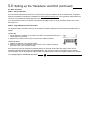
STEP 1 - Set-up OD4 Links
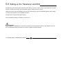
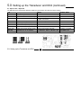
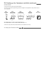
If the transducer characteristics are known, set the frequency and input resistance links as required. A list of standard
settings for all Solartron transducers is available from www.solartronmetrology.com. If the transducer characteristics are
not known, the standard link settings should be used.
If your transducer is known to be outside of the standard sensitivity range, the X2 or DIV2 links will have to be used.
See section 5.3.
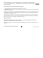
STEP 2 - Align OD4 Null and Transducer Null
Null the OD4.
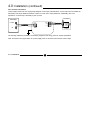
1. Put the Gain link on position (7) as shown. This allows any electronics offset in the
output stage to be removed.
2. Adjust the Fine Offset control to give as near to zero output as practical.
Null the transducer.
1. Replace the Gain link to the original position.
2. Adjust the position of the transducer to give as near to zero output as practical.
This is the centre of the mechanical range.
NULL
Any electrical offset in the OD4 is removed. The transducer position is adjusted so that transducer and OD4 nulls are
aligned.
FREQ
LO
(ON) 1 2 3 4 5 6 (7)
HI
(OFF)
If the transducer cannot be centered for practical reasons an offset will remain within the system. There may be
noticeable interaction between Gain and Offset adjustment. This does not prevent the OD4 being set-up. However
several iterations may be required when adjusting Gain and Offset. Please contact your supplier if guidance is required.
5.0: Setting up the Transducer and OD4
16
Part No. 502621 Issue 8