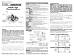
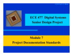
1
STM32-H405 development board USER’S MANUAL Revision A, November 2015 Designed by OLIMEX Ltd, 2015 All boards produced by Olimex LTD are ROHS compliant OLIMEX© 2015 STM32-H405 user's manual DISCLAIMER © 2015 Olimex Ltd. Olimex®, logo and combinations thereof, are registered trademarks of Olimex Ltd. Other product names may be trademarks of others and the rights belong to their respective owners. The information in this document is provided in connection with Olimex products. No license, express or implied or otherwise, to any intellectual property right is granted by this document or in connection with the sale of Olimex products. The hardware design of STM32-H405 development board is considered propriety. The board's schematics are available in pdf format. The original schematic and design files are not available to the public. The part of the software written by Olimex is released under GPL. However, note that the examples that we distribute are based on the libraries and projects released by IAR Systems. Make sure that you are acquainted with the license agreement of IAR Embedded Workbench before using, publishing, or distributing any code based on the software released by Olimex. It is possible that the pictures in this manual differ from the actual appearance of the latest revision of the board. The product described in this document is subject to continuous development and improvements. All particulars of the product and its use contained in this document are given by OLIMEX in good faith. However all warranties implied or expressed including but not limited to implied warranties of merchantability or fitness for purpose are excluded. This document is intended only to assist the reader in the use of the product. OLIMEX Ltd. shall not be liable for any loss or damage arising from the use of any information in this document or any error or omission in such information or any incorrect use of the product. This evaluation board/kit is intended for use for engineering development, demonstration, or evaluation purposes only and is not considered by OLIMEX to be a finished end-product fit for general consumer use. Persons handling the product must have electronics training and observe good engineering practice standards. As such, the goods being provided are not intended to be complete in terms of required design-, marketing-, and/or manufacturing-related protective considerations, including product safety and environmental measures typically found in end products that incorporate such semiconductor components or circuit boards. Olimex currently deals with a variety of customers for products, and therefore our arrangement with the user is not exclusive. Olimex assumes no liability for applications assistance, customer product design, software performance, or infringement of patents or services described herein. THERE IS NO WARRANTY FOR THE DESIGN MATERIALS AND THE COMPONENTS USED TO CREATE STM32-H405. THEY ARE CONSIDERED SUITABLE ONLY FOR STM32-H405. Page 2 of 31 OLIMEX© 2015 STM32-H405 user's manual Table of Contents DISCLAIMER......................................................................................................................................2 CHAPTER 1 OVERVIEW...................................................................................................................5 1. Introduction to the chapter...........................................................................................................5 1.1 Features......................................................................................................................................5 1.2 Target market and purpose of the board.....................................................................................6 1.3 Similar boards............................................................................................................................6 1.4 Document Organization.............................................................................................................6 CHAPTER 2: BOARD DESCRIPTION..............................................................................................7 2.1 Layout (top view).......................................................................................................................7 2.2 Layout (bottom view)................................................................................................................ 8 2.3 EXT pinout (bottom view).........................................................................................................9 CHAPTER 3 SETTING UP THE STM32-H405 BOARD................................................................10 3. Introduction to the chapter.........................................................................................................10 3.1 Electrostatic warning............................................................................................................... 10 3.2 Requirements........................................................................................................................... 10 3.2.1 Hardware requirements:...................................................................................................10 3.2.2 Software requirements:.................................................................................................... 11 3.3 Powering the board..................................................................................................................12 3.4 Programming the board........................................................................................................... 12 3.4.1 Using JTAG debugger......................................................................................................12 3.4.2 Using USB cable..............................................................................................................12 3.5 Prebuilt software......................................................................................................................13 CHAPTER 4 THE STM32F405 MICROCONTROLLER................................................................ 14 4. Introduction to the chapter.........................................................................................................14 4.1 The STM32F405RG features...................................................................................................14 CHAPTER 5 CONTROL CIRCUITY AND HARDWARE MODULES..........................................16 5. Introduction to the chapter.........................................................................................................16 5.1 Reset.........................................................................................................................................16 5.2 Clocks...................................................................................................................................... 16 5.3 Power supply circuit................................................................................................................ 16 CHAPTER 6 CONNECTORS AND PINOUT.................................................................................. 18 6. Introduction to the chapter.........................................................................................................18 6.1 USB connector.........................................................................................................................18 6.2 JTAG/SWD debug connector.................................................................................................. 19 6.3 EXT connectors....................................................................................................................... 20 6.3.1 EXT1 header.................................................................................................................... 20 6.3.2 EXT2 header.................................................................................................................... 21 6.4 Jumper description...................................................................................................................21 6.4.1 BOOT memory select jumpers.........................................................................................21 Page 3 of 31 OLIMEX© 2015 STM32-H405 user's manual 6.4.2 R-T jumper.......................................................................................................................22 6.4.3 VBAT signal and jumper..................................................................................................22 6.4.4 LED_E............................................................................................................................. 22 6.4.5 USBP_E........................................................................................................................... 22 6.5 Additional hardware components............................................................................................ 23 CHAPTER 7 BLOCK DIAGRAM AND MEMORY........................................................................24 7. Introduction to the chapter.........................................................................................................24 7.1 Processor family block diagram.............................................................................................. 24 7.2 Physical memory map..............................................................................................................25 CHAPTER 8 SCHEMATICS.............................................................................................................26 8. Introduction to the chapter.........................................................................................................26 8.1 Eagle schematic....................................................................................................................... 26 8.2 Physical dimensions.................................................................................................................28 CHAPTER 9 REVISION HISTORY AND SUPPORT......................................................................29 9. Introduction to the chapter.........................................................................................................29 9.1 Document revision...................................................................................................................29 9.2 Board revision..........................................................................................................................29 9.3 Useful web links and purchase codes......................................................................................30 9.4 Product support........................................................................................................................31 Page 4 of 31 OLIMEX© 2015 STM32-H405 user's manual CHAPTER 1 OVERVIEW 1. Introduction to the chapter Thank you for choosing this general-purpose development board designed and assembled by Olimex! This document provides a user’s guide for the Olimex STM32-H405 board. As an overview, this chapter gives the scope of this document and lists the board’s features. A comparison between boards similar to STM32-H405 is presented. The document’s organization is then detailed. The STM32-H405 development board enables code development of applications running on the microcontroller STM32F405RG, manufactured by STMicroelectronics. STM32-H405 board is an entry level development board for the new ARM Cortex M4 family of devices produced by STMicroelectronics Inc. With STM32-H405 you can explore the features of STM32 family on budged, the board has everything necessary to build simple applications: USB port where power is taken and power supply circuit, reset and oscillator circuits, JTAG port for programming and debugging, programmable LED and programmable button. Although a very simple board, it is sufficient enough for building USB applications like PC mouse, USB mass storage device, USB audio class device, USB to virtual RS232 port. There are plenty of GPIOs on the extension headers which can be used to connect your additional circuits. 1.1 Features The board has the following list of features: • • • • • • • • • • • • • • • MCU: STM32F405RG ARM Cortex M4 in LQFP64 pacakge that operates up to 168 Mhz; with 1024KB flash memory; (192+4)kB SRAM; 2×USB; 2×CAN; 2 x I2C; 3×12-bit ADC×16 channels; 2×12-bit DAC; 2×UART; 3×SPI; 17 timers; with up to 51 GPIOs Standard JTAG connector with ARM 2×10 pin layout for programming/debugging with ARM-JTAG USB type B connector User button RESET button User LED Power supply LED On-board voltage regulator 3.3V with up to 800mA current Single power supply: takes power from USB port or extension connector pin 8 Mhz crystal oscillator 32768 Hz crystal and RTC backup battery connector Extension headers with 0.1" step for all uC ports PCB: FR-4, 1.5 mm (0,062") Dimensions: (61×34)mm ~ (2.4×1.3)" Distance between the ext connectors: 25.4mm ~ 1" Page 5 of 31 OLIMEX© 2015 STM32-H405 user's manual 1.2 Target market and purpose of the board STM32-H405 is a development board featuring a ARM Cortex-M4 microcontroller. The board can be powered by a number of different sources. It can be programmed with a debugger via JTAG or SWD, or alternatively with a cable via USB. The bpard has a lot of GPIO pins exposed. The board is suitable for numerous tasks and situations. The power of ARM and the creativity of OLIMEX come at the best price and the well-known quality. Every ARM enthusiast would see STM32-H405 as an interesting bargain and quite capable board for its low price. 1.3 Similar boards The STM32H405RG microcontroller is also present in two other Olimex-made boards – STM32P405 and STM32-405STK. Both boards have more built-in peripherals compared to STM32-H405. STM32-P405 has MMC card interface with connector, UEXT connector, CAN interface with connector, UART interface with DE-9 connector, built-in power barrel jack, and a small prototype area. STM32-405STK has micro SD card interface with connector, mini USB, 84x48 BW display, microphone input with connector; headphone output with connector, UEXT connector. The board can be powered by a 1.5V AA battery – there is a battery holder provided. Another board, quite similar to STM32-H405, is STM32-H103; the board designs are almost identical – the main difference is that STM32-H103 uses STM32F103RB. If you are looking for a board with similar processor and Ethernet functionality take a look at STM32-E407 board. It uses STM32H407ZG. 1.4 Document Organization Each section in this document covers a separate topic, organized as follow: – Chapter 1 is an overview of the board usage and features – Chapter 2 contains the board's layout – Chapter 3 provides a guide for quickly setting up the board – Chapter 4 describes the component that is the heart of the board: the STM32F405 microcontroller – Chapter 5 is an explanation of the control circuitry associated with the microcontroller to reset. Also shows the clocks on the board – Chapter 6 covers the connector pinout, peripherals and jumper description – Chapter 7 shows the block diagram and the memory map – Chapter 8 provides the schematics – Chapter 9 contains the revision history, useful links and support information Page 6 of 31 OLIMEX© 2015 STM32-H405 user's manual CHAPTER 2: BOARD DESCRIPTION In this chapter you will get acquainted with the main parts of the board. Note the names used on the board differ from the names used to describe them. For the actual names check the STM32-H405 board itself. 2.1 Layout (top view) The picture below shows the top side of the board and highlights the most important parts. Notice that all on-board jumpers are SMD type – in order to change the position of the jumpers you would either need to cut between the pads of the jumper or solder the pads together. Page 7 of 31 OLIMEX© 2015 STM32-H405 user's manual 2.2 Layout (bottom view) The two most important parts at the bottom of the board are the two 26-pin headers EXT1 and EXT2. They allow easier access to some of the pins of the microcontroller. Refer to the pinout on the next page for more detailed information on the signals available on EXT1 and EXT2. Page 8 of 31 OLIMEX© 2015 STM32-H405 user's manual 2.3 EXT pinout (bottom view) Page 9 of 31 OLIMEX© 2015 STM32-H405 user's manual CHAPTER 3 SETTING UP THE STM32-H405 BOARD 3. Introduction to the chapter This section helps you set up the STM32-H405 development board for the first time. Please consider first the electrostatic warning to avoid damaging the board, then discover the hardware and software required to operate the board. The procedure to power up the board is given, and a description of the default board behavior is detailed. 3.1 Electrostatic warning STM32-H405 is shipped in a protective anti-static package. The board must not be exposed to high electrostatic potentials. A grounding strap or similar protective device should be worn when handling the board to avoid electrostatic discharge. 3.2 Requirements In order to set up the STM32-H405 optimally you would need a hardware debugger tool and compatible software tools. More detailed information may be found in the sub-chapters below: 3.2.1 Hardware requirements: - Standard ARM JTAG/SWD debugger/programmer – it can power the board and gives you the ability to program/debug the board – to select the correct tool make sure that it is compatible with the software tools which you are going to use during development. Also makes sure that the tool is compatible with the STM32F405 processor. IMPORTANT: The board can be programmed using only a USB cable. However, it is a slow process – this way of programming is not suitable for evaluation, research and development. Using the USB DFU bootloader might be good idea only if you need to program the board once or twice. Additional components can be acquired in order to increase the functionality of the board: - USB cable with type A and type B connectors – in case you want to power the board from the USB port of your personal conputer or, alternatively, if you want need to utilize the board's USB interface - Jumper wires – allow solderless access to the exposed pins; if you want to directly connect to the extension headers use wires with a female connectors. Some of the suggested items can be purchased by Olimex, for instance: ARM-USB-TINY-H – high-speed OpenOCD ARM JTAG debugger ARM-USB-OCD-H – high-speed OpenOCD ARM JTAG debugger with buffer protection ARM-JTAG-COOCOX – high-speed CooCox IDE JTAG/SWD debugger USB-A-B-CABLE – cable with USB type A and USB type B connectors at each end JW-200x10-FM – ten jumper wires with female-male connectors Page 10 of 31 OLIMEX© 2015 STM32-H405 user's manual 3.2.2 Software requirements: In order to change the code on the board you would need an ARM C compiler and debugger software, the possible software options are: - free open-source software: OpenOCD (all Olimex OpenOCD JTAG debuggers are supported in OpenOCD) - free software: CooCox IDE (all Olimex JTAGs are supported in CooCox) - commercial software: EW-ARM from IAR Systems AB; CrossWorks from Rowley (all Olimex OpenOCD JTAG debuggers are supported in IAR and Rowley Crossworks; note that our debugging tools doesn't work in Keil MDK-ARM). Comparison table Is it free or commercial Initial struggle and set-up time STM32-H405 Is it example openprovided by source Olimex Does it work with Olimex OpenOCD debuggers Quality of customer support OpenOCD Free Highest No Yes Yes Bad CooCox IDE Free High No No Yes Mediocre Rowley Crossworks for ARM Commercial (free time-limited evaluation version) Low No No Yes Good Keil MDK-ARM Commercial (free size-limited evaluation version) Low No No No Good IAR EW for ARM Commercial (free size-limited version and free time-limited evaluation version) Low Yes No Yes Good It is a good idea to study the example that is provided by Olimex for your board. If you are not willing to purchase the software just use the evaluation version initially. Specifically, for STM32-H405 Olimex provides only IAR EW for ARM example. It is a good idea to download the latest time-limited evaluation version. Page 11 of 31 OLIMEX© 2015 STM32-H405 user's manual 3.3 Powering the board The board can be powered in one of the following ways: 1) Using the JTAG or SWD debugger – the board gets powered via the 20-pin 0.1” step JTAG connector; note that some tool might hold the board in RESET state – make sure to release the microcontroller from RESET to be able to see the execution of your code 2) Using USB cable – the board gets powered via the USB connector; the power is provided, typically, by your computer's USB port 3) Using external power supply – in this case, the board gets powered via the EXT2 header – provide +5V DC to pin #26 of this header; then connect the power supply's GND to pin #25 of EXT2. 3.4 Programming the board The programming of the board is also fairly straight forward (unlike the software development for the board): 3.4.1 Using JTAG debugger This is the recommended method of changing the software of the board. This is fairly simple from hardware point of view – just plug the male 20-pin JTAG connector of your hardware tool to the 20pin female JTAG connector of STM32-H405. Refer to the documentation of your debugger and also to the documentation of the software of choice on instructions how to set the environment. 3.4.2 Using USB cable The board can be programmed without a debugger tool. In this case you only need a personal computer that is able to run Windows software and an USB cable. STM32-H405 has a built-in USB DFU bootloader that allows such programming. Programming STM32-H405 via the bootloader is a slow process that requires the re-configuration of SMD jumper. It is not recommend for initial evaluation, research and development (use any ARM JTAG debugger instead). Using the bootloader might be good idea only if you need to program the board once or twice. How to do it: 1. Change the position of one of the boot SMD jumpers – B0_H/B0_L (the bottom one). By default it is set to position B0_L – you need to change it to B0_H. This requires soldering. 2. After the adjustment is done you can connect to the DfuSe software released by STM. It available for download from STM's official web-site. Search for “STSW-STM32080”. 3. Install the software and run it. Page 12 of 31 OLIMEX© 2015 STM32-H405 user's manual 4. Connect the board via the USB cable to the personal computer. 5. The board should now be recognized in the software. The bootloader application provided by STM32 is a bit strange. It works only with dfu files. To upload other binary files (hex, bin, s19) you would need to use additional converter tool (“DFU File Manager”; it converts hex, bin, s19 to dfu and vice versa). I highly recommend you to read carefully the document about the usage of the Dfuse called “Getting started with DfuSe USB device firmware upgrade”. Search for “UM0412”. 6. Note that once you've uploaded the software you would need to change the jumpers back to the original position – else the bootloader would start every time and the user program (typically stored in the flash memory) would not execute. 3.5 Prebuilt software Upon powering the board the STAT and PWR LEDs should turn on. The board comes with the software which was downloaded and used during the testing of the board. This software and its source code could not serve any purpose to the customer, who purchased the board, since it requires additional custom hardware. That is why there is a meaningful example available for download at the web-page of the board. Please download and extract the following archive which contains the recommended initial demo: https://www.olimex.com/Products/ARM/ST/STM32-H405/resources/STM32-H405_examples.zip Note that the demo can opened and compiled out-of-the-box ONLY with IAR Embedded Workbench for ARM. You can get a free code-size or time-limited evaluation version of IAR EW for ARM from their official web-site (requires registration). Refer to the “ReadMe.txt” file inside the archive for more information. Page 13 of 31 OLIMEX© 2015 STM32-H405 user's manual CHAPTER 4 THE STM32F405 MICROCONTROLLER 4. Introduction to the chapter Some of the details about the main processor in the design of STM32-H405 (STM32F405RG) are mentioned in this chapter. The information is a modified version of the datasheet provided by its manufacturers from ST. It is highly recommended to refer to the original datasheet which might be downloaded from the ST's official web-side. 4.1 The STM32F405RG features STM32-H405 board uses STM32F405RG microcontroller designed and manufactured by STMicroelectronics. The main processor of the board is one of the biggest processors of the PIC32MZ family. It has the following features that distinguish it from the rest of the family: Core: ARM 32-bit Cortex™-M4 CPU with FPU, Adaptive real-time accelerator (ART Accelerator™) allowing 0-wait state execution from Flash memory, frequency up to 168 MHz, memory protection unit, 210 DMIPS/1.25 DMIPS/MHz (Dhrystone 2.1), and DSP instructions Memories 1 Mbyte of Flash memory 192+4 Kbytes of SRAM including 64-Kbyte of CCM (core coupled memory) data RAM Flexible static memory controller supporting Compact Flash, SRAM, PSRAM, NOR and NAND memories LCD parallel interface, 8080/6800 modes Clock, reset and supply management 1.8 V to 3.6 V application supply and I/Os POR, PDR, PVD and BOR 4-to-26 MHz crystal oscillator Internal 16 MHz factory-trimmed RC (1% accuracy) 32 kHz oscillator for RTC with calibration Internal 32 kHz RC with calibration Sleep, Stop and Standby modes VBAT supply for RTC, 20×32 bit backup registers + optional 4 KB backup SRAM 3×12-bit, 2.4 MSPS A/D converters: 24 channels and 7.2 MSPS in triple interleaved mode 2×12-bit D/A converters General-purpose DMA: 16-stream DMA controller with FIFOs and burst support Up to 17 timers: up to twelve 16-bit and two 32-bit timers up to 168 MHz, each with up to 4 IC/OC/PWM or pulse counter and quadrature (incremental) encoder input Debug mode Serial wire debug (SWD) & JTAG interfaces Cortex-M4 Embedded Trace Macrocell™ 114 I/O ports with interrupt capability Up to 15 communication interfaces 3 × I2C interfaces (SMBus/PMBus) Page 14 of 31 OLIMEX© 2015 STM32-H405 user's manual 4 USARTs/2 UARTs (10.5 Mbit/s, ISO 7816 interface, LIN, IrDA, modem control) 3 SPIs (37.5 Mbits/s), 2 with muxed full-duplex I2S to achieve audio class accuracy via internal audio PLL or external clock 2 × CAN interfaces (2.0B Active) SDIO interface Advanced connectivity USB 2.0 full-speed device/host/OTG controller with on-chip PHY USB 2.0 high-speed/full-speed device/host/OTG controller with dedicated DMA, onchip full-speed PHY and ULPI 10/100 Ethernet MAC with dedicated DMA: supports IEEE 1588v2 hardware, MII/RMII 8- to 14-bit parallel camera interface up to 54 Mbytes/s True random number generator CRC calculation unit 96-bit unique ID RTC: subsecond accuracy, hardware calendar For comprehensive information on the microcontroller visit the ST’s web page for a datasheet. At the moment of writing the microcontroller datasheet can be found at the following link: http://www.st.com/st-web-ui/static/active/en/resource/technical/document/datasheet/DM00037051.pdf Page 15 of 31 OLIMEX© 2015 STM32-H405 user's manual CHAPTER 5 CONTROL CIRCUITY AND HARDWARE MODULES 5. Introduction to the chapter Here you can find information about reset circuit and quartz crystals locations, the power supply circuit is discussed. 5.1 Reset The reset circuit is connected to pin #7 (NRST) of the STM32F405RG microcontroller. STM32H405's reset circuit includes R8 (10 kΩ), C19 (100nF) and a RESET button. The reset signal is also available on pin #25 of the EXT1 header. It is also available at pin #15 of the JTAG connector. 5.2 Clocks There are two quartz crystals available on the board: 8 MHz quartz crystal Q1 is connected to pins 5 and 6 of the ARM microcontroller. Quartz crystal Q2 is a 32768Hz RTC (real-time clock) and it is connected to microcontroller's pins 3 and 4. 5.3 Power supply circuit The power supply circuit of STM32-H405 allows the board to be powered by three sources. The most used interface for powering is the USB type B connector. It works at 5V DC. The board can also be powered via the on-board JTAG connector. In that case the board receives 3.3V DC from the debugger tool. Finally, the board can be powered from the EXT headers. The best location to power the board would be pins #26 (+5V DC) and #26 (GND) from the EXT2 connector. Double check the pin locations before providing the power. If you want to use a back-up battery consider using pin #23 of EXT1 header that works with batteries providing voltage in the (2.0-3.3)V range. This VBAT pin allows to power the device VBAT domain from an external battery, an external supercapacitor, or from VDD when no external battery and an external supercapacitor are present. VBAT operation is activated when VDD is not present. The VBAT pin supplies the RTC, the backup registers and the backup SRAM. The board consumes around 0.2W (e.g. 0.04A at 5V) with both LEDs on. By default, if you have successfully powered the board both LEDs would turn on. In case you you have modified the software the green LED might not turn on since it is initialized by the code Page 16 of 31 OLIMEX© 2015 STM32-H405 user's manual loaded on-board. The red LED should always turn on upon powering. Note that it is possible to have the PWR LED on even if there isn't enough power for proper operation of the board and all the peripherals currently connected. Page 17 of 31 OLIMEX© 2015 STM32-H405 user's manual CHAPTER 6 CONNECTORS AND PINOUT 6. Introduction to the chapter In this chapter are presented the connectors that can be found on the board all together with their pinout and notes about them. Jumpers functions are described. Notes and info on specific peripherals are presented. Notes regarding the interfaces are given. 6.1 USB connector The USB type B connector allows you to access the USB functionality of STM32-H405. This connector is can be used to power the board. The connector is sturdy and typically lasts much longer during extensive use compared to the USB mini or USB micro connectors. Note the DFU bootloader uses the USB port. The signals follow the familiar and standard USB pattern: USB Type B PIN# SIGNAL NAME 1 +5V_USB 2 USBDM 3 USBDP 4 GND Page 18 of 31 OLIMEX© 2015 STM32-H405 user's manual 6.2 JTAG/SWD debug connector The board can be debugged from the 20-pin JTAG connector either by a debugger with compatible connector. The on-board JTAG connector has 0.1” step of its pins. Below is the table with the signals of the JTAG. This interface can be used with the Olimex's OpenOCD debuggers. It is also compatible with most of the ARM debuggers available on the market. JTAG/SWD debug connector Pin # Signal Name Pin # Signal Name 1 3.3V 2 3.3V 3 TRST 4 GND 5 TDI 6 GND 7 TMS 8 GND 9 TCK 10 GND 11 GND 12 GND 13 TDO 14 GND 15 RST 16 GND 17 GND 18 GND 19 GND 20 GND Page 19 of 31 OLIMEX© 2015 STM32-H405 user's manual 6.3 EXT connectors At the bottom of the board there are two extension rows of pins. These 2 x 26-pin connectors combine different processor ports and provide very nice GPIO option – you can interface the signals exposed with your breadboarding wires; you can use them as headers; you can take signal readings; etc. The distance between two pins from the same row is 0.1''. The distance between the two EXT connectors is exactly 1''. Refer to sub-chapter 2.3 “EXT pinout (bottom view)” for visual representation of each pin of the connectors. 6.3.1 EXT1 header EXT1 HEADER PIN # STM32H405 PIN PIN # STM32H405 PIN 1 PA11 2 PA8 3 PA12 4 PA9 5 3.3V (VDD) 6 GND 7 PA10 8 PC10 9 PC11 (DISC) 10 PC12 (LED) 11 PD2 12 PB5 13 PB6 14 PA6 15 PB7 16 PB8 17 PB9 18 PA5 19 PC0 20 PC1 21 PB0 22 PA7 23 VBAT 24 PC13 25 RST 26 PB1 Page 20 of 31 OLIMEX© 2015 STM32-H405 user's manual 6.3.2 EXT2 header EXT2 HEADER PIN # STM32H405 PIN PIN # STM32H405 PIN 1 VDDA 2 PC2 3 VSS (AGND) 4 PA0 5 3.3V (VDD) 6 GND 7 PA2 8 PA1 9 PC3 10 PA3 11 PA4 12 PC4(USB_P) 13 PC5 14 PB10 15 PB11 16 PB13 17 PB12 18 PB14 19 PB15 20 PC6 21 PC7 22 PC8 23 +5V_USB 24 PC9 25 GND_VSS 26 VIN 6.4 Jumper description Please note that all of the jumpers on the board are SMD type. If you feel insecure in your soldering/cutting technique it is better not to adjust the SMD jumpers. 6.4.1 BOOT memory select jumpers B1_H/B1_L and B0_H/B0_L are SMD jumpers which define the initial boot default priority of the microcontroller (aka which memory to boot from). By default they are set so that the board would boot from the user Flash memory. Notice that these two jumpers must be moved together – they are responsible for the boot mode if bootloader is present. The board can search for bootloader on three places – either the user Flash memory, the System memory, or the Embedded SRAM. By default, B0_H/B0_L is set to position B0_L; the other jumper B1_H/B1_L is set to B1_L – in this configuration the board will try to boot from user Flash memory. To boot from the system memory you need to change the position of B0_H/B0_L jumper to position B0_H. The boot loader is located in system memory (if you want to program the board via the USB and DFUse software – use this mode). Changing both high positions (B0_H/B0_L to B0_H; and B1_H/B1_L to B1_H) would attempt to boot from the Embedded SRAM. Page 21 of 31 OLIMEX© 2015 STM32-H405 user's manual Refer to the “STM32 microcontroller system memory boot mode” document (“AN2606”) for more information about the bootloader available on STM32F4xx microcontrollers. 6.4.2 R-T jumper If you close this jumper RST and TRST at the JTAG will be connected. The default R-T position is open. 6.4.3 VBAT signal and jumper The VBAT pin supplies the RTC, the backup registers and the backup SRAM. VBAT signal is available at pin #23 of EXT1 header – this is a good place to connect a back-up battery that provides voltage in the (2.0-3.3)V range. Opening this jumper would disconnect pin #23 of EXT1 header from the STM32F405. The default VBAT position is closed. 6.4.4 LED_E Opening this jumper will disable the user LED. The default position is closed. 6.4.5 USBP_E Opening this jumper would disable the option to power the board from the USB connector. The default position is closed. Page 22 of 31 OLIMEX© 2015 STM32-H405 user's manual 6.5 Additional hardware components The hardware components below are mounted on STM32-H405 but are not discussed above. These are listed here for completeness: RESET button – used for hardware reset of the board; typically cannot be re-programmed; connected to STM32F405's pin #7 (NRST) BUT button – customizable button; can be re-programmed by the user – connected to STM32F405's pin #14 (PA0); also available at pin #4 of the EXT2 header PWR LED – indicates when the board is powered; cannot be re-programmed; it is not connected to the main microcontroller STAT LED – customizable LED; can be re-programmed by the user – connected to STM32F405's pin #53 (PC12); also available at pin #10 of the EXT1 header; this LED can also be disabled if you disconnect jumper LED_E; the jumper pads can also be used for measrements Page 23 of 31 OLIMEX© 2015 STM32-H405 user's manual CHAPTER 7 BLOCK DIAGRAM AND MEMORY 7. Introduction to the chapter On the next page you can find a memory map for this family of processors. It is strongly recommended to refer to the original datasheet released by STMicroelectronics for one of higher quality. 7.1 Processor family block diagram Page 24 of 31 OLIMEX© 2015 STM32-H405 user's manual 7.2 Physical memory map STM32F405RG has 1024Kbytes of flash memory and (192 + 4)Kbytes of SRAM. Inspecting the map below don't forget that all STM32F405YY microcontrollers have neither Ethernet controller nor camera interface. STM32F405RG also lacks FSMC memory controller. Page 25 of 31 OLIMEX© 2015 STM32-H405 user's manual CHAPTER 8 SCHEMATICS 8. Introduction to the chapter In this chapter are located the schematics describing logically and physically STM32-H405. 8.1 Eagle schematic STM32-H405 schematic is visible for reference here. You can also find them on the web page for STM32-H405 at our site: https://www.olimex.com/Products/ARM/ST/STM32-H405/ They are located in HARDWARE section. The EAGLE schematic is situated on the next page for quicker reference. Page 26 of 31 OLIMEX© 2015 STM32-H405 user's manual 3.3V 3.3V 3.3V R18 10K 2. When STM32F103RB (in LQFP64) is mounted, C20 and C23 must be connected in short circuit (for example via 0 Ohm resistor)! 2 R19 VCC BUT For the STM32F405RG (in LQFP64), please see the corresponding datasheet! U1 C11 RST 1 RESET 0 2 13 C9 10uF/10V 100nF VBAT 12 1 1 EXT1-23 GND BUT 560 C7 47 63 10K 10K 10K 10K 1 4 3 TRST 6 5 TDI 8 7 TMS 10 9 12 11 14 13 TDO 16 15 RST 18 17 20 19 BUT R2 R3 10K 10K 47K JTAG +5V_USB USB_P 3.3V R1 15K 3.3V EXT2-23 2x13 R11 10K Q4 BC817 R27 Q3 BC817 R17 PA0-WKUP/USART2_CTS/ADC0/TIM2_CH1_ETR PC4/ADC14 24 USB_P PC5/ADC15 25 PA12/USART1_RTS/CANTX/USBDP/TIM1_ETR PA14/JTCK/SWCLK 6 R22 22 PA15/JTDI/TIM2_CH1_ETR/SPI1_NSS C17 C10 100nF LED C15 Q2 32768 R12 1M EXT1-11 C16 47pF(NA) 47pF(NA) VDDA IN C1 100nF 100nF EXT2-25 VCC OUT 3.3V R10 ADJ/GND C2 R9 C4 R7 390/1% EXT1-5 EXT1-6 EXT2-3 3.3V PWR C24 C3 R16 0R 0R(Board_Mounted) Page 27 of 31 2k EXT2-1 C22 100nF 3.3V VR LM1117 240/1% USBDP EXT2-26 STM32-H405, BOARD REVISION C STM32-H103, BOARD REVISION C THE SCHEMATIC IS SUITABLE FOR BOTH BOARDS, MIND THE NOTES AT THE TOP OF THE SCHEMATIC! OLIMEX LTD, BULGARIA WWW.OLIMEX.COM EXT2-5 EXT2-6 10pF GND C14 10pF C12 27pF Q1 8MHz C13 STM32F103RBT6(LQFP64) C21 USBDM R21 22 U3 PD2/TIM3_ETR 54 VIN 1N5819S NA 5 R4 2k PD0/OSC_IN 5 PD1/OSC_OUT 6 PA13/JTMS/SWDIO D2 VIN 1 PC14/OSC32_IN 3 PC15/OSC32_OUT 4 PA11/USART1_CTS/CANRX/USBDM/TIM1_CH4 45 VIN 2 PC12/USART3_CK 53 LED PC13/ANTI_TAMP 2 PA10/USART1_RX/TIM1_CH3 44 1N5819S D1 4 PC10/USART3_TX 51 PC11/USART3_RX 52 DISC EXT2-9 EXT2-12 EXT2-13 EXT2-20 EXT2-21 EXT2-22 EXT2-24 EXT1-8 EXT1-9 EXT1-10 EXT1-24 STAT led0603/green TRST,TDI,TMS,TCK,TDO,RST 1.5K 3 PC8/TIM3_CH3 39 PC9/TIM3_CH4 40 PA9/USART1_TX/TIM1_CH2 43 EXT1-19 EXT1-20 EXT2-2 PC6/TIM3_CH1 37 PC7/TIM3_CH2 38 PA8/USART1_CK/TIM1_CH1/MCO 42 33K 3.3V USB PC2/ADC12 10 PC3/ADC13 11 PA7/SPI1_MOSI/ADC7/TIM3_CH2/TIM1_CH1N 41 R15 33K 3.3V R20 +5V_USB 4 BOOT0 PA6/SPI1_MISO/ADC6/TIM3_CH1/TIM1_BKIN 23 50 NRST PC0/ADC10 8 PC1/ADC11 9 3 0 EXT2-16 PB14/SPI2_MISO/USART3_RTS/TIM1_CH2N 35 EXT2-18 PB15/SPI2_MOSI/TIM1_CH3N 36 EXT2-19 PA5/SPI1_SCK/ADC5 22 49 1 PB12/SPI2_NSS/I2C2_SMBAL/USART3_CK/TIM1_BKIN BOOT0 33 EXT2-17 PB13/SPI2_SCK/USART3_CTS/TIM1_CH1N 34 PA4/SPI1_NSS/USART2_CK/ADC4 21 TDI VCAP_2 PA3/USART2_RX/ADC3/TIM2_CH4 20 TCK VCAP_1 VSS PA2/USART2_TX/ADC2/TIM2_CH3 17 46 VSS PA1/USART2_RTS/ADC1/TIM2_CH2 16 TMS default_to_B0_L PB10/I2C2_SCL/USART3_TX/TIM2_CH3 29 EXT2-14 PB11/I2C2_SDA/USART3_RX/TIM2_CH4 30 STM32F405RGT6(LQFP64) R29 22K 3 15 47K 1K 2 14 BUT R26 DISC 1 EXT2-4 EXT2-8 EXT2-7 EXT2-10 EXT2-11 EXT1-18 EXT1-14 EXT1-22 EXT1-2 EXT1-4 EXT1-7 EXT1-1USBDM EXT1-3USBDP TCK R24 60 BOOT0 10K 2 EXT1-25 RST R-T 0 B0_H/B0_L EXT1-15 VSS 7 RST 3.3V PB8/TIM4_CH3/I2C1_SCL/CANRX EXT1-16 61 PB9/TIM4_CH4/I2C1_SDA/CANTX EXT1-17 62 VSS 18 R25 PB6/I2C1_SCL/TIM4_CH1/USART1_TX 58 EXT1-13 PB7/I2C1_SDA/TIM4_CH2/USART1_RX 59 EXT2-15 31 RST R5 VDD 10uF/10V C202.2uF/6.3V C232.2uF/6.3V R6 PB4/JTRST/TIM3_CH1/SPI1_MISO 56 TRST PB5/I2C1_SMBAI/TIM3_CH2/SPI1_MOSI 57 3 0 R28 33K VBAT VDD C8 3.3V R23 R13 PB2/BOOT1 28 PB3/JTDO/TIM2_CH2/TRACESWO/SPI1_SCK 55 TDO VDD 64 C6 VSSA VDD 19 C5 PB0/ADC8/TIM3_CH3/TIM1_CH2N 26 EXT1-21 PB1/ADC9/TIM3_CH4/TIM1_CH3N 27 EXT1-12 48 100nF 1 VDDA EXT1-26 32 C19 C18 100nF B1_H/B1_L default_to_B1_L 3. U1's symbol refers to STM32F103RB (in LQFP64). R8 10k U2 NA 3.3V 1. When STM32F405RG (in LQFP64) is mounted, C20 and C23 must be populated! VDDA L1 ferrite bead 27pF OLIMEX© 2015 STM32-H405 user's manual 8.2 Physical dimensions Note that all dimensions are in thousandths of an inch (mil). Page 28 of 31 OLIMEX© 2015 STM32-H405 user's manual CHAPTER 9 REVISION HISTORY AND SUPPORT 9. Introduction to the chapter In this chapter you will find the current and the previous version of the document you are reading. Also the web-page for your device is listed. Be sure to check it after a purchase for the latest available updates and examples. 9.1 Document revision Revision, Date A, 26.11.15 Changes Modified pages Initial release 9.2 Board revision Revision, Date C, 21.02.14 Revision notes Initial release Page 29 of 31 All OLIMEX© 2015 STM32-H405 user's manual 9.3 Useful web links and purchase codes The web page you can visit for more info on your device is: https://www.olimex.com/Products/ARM/ST/STM32-H405/ The official Olimex forums are located here: https://www.olimex.com/forum ORDER CODES: STM32-H405 – the version of the board discussed in this document STM32-P405 – a similar board with more peripherals STM32-405STK – a similar board with even more peripherals ARM-USB-TINY-H – OpenOCD compatible high-speed debugger/programmer with JTAG interface ARM-USB-OCD-H – OpenOCD compatible debugger/programmer with JTAG interface, protection buffers and better power supply circuit How to order? You can order directly from our web-shop or via any of our distributors. List of Olimex distributors may be found here: https://www.olimex.com/Distributors/ Please check https://www.olimex.com/ for more information. Page 30 of 31 OLIMEX© 2015 STM32-H405 user's manual 9.4 Product support For product support, hardware information and error reports mail to: [email protected]. All document or hardware feedback is welcome. Note that we are primarily a hardware company and our software support is limited. Please consider reading the paragraph below about the warranty of Olimex products. All goods are checked before they are sent out. In the unlikely event that goods are faulty, they must be returned, to OLIMEX at the address listed on your order invoice. OLIMEX will not accept goods that have clearly been used more than the amount needed to evaluate their functionality. If the goods are found to be in working condition, and the lack of functionality is a result of lack of knowledge on the customers part, no refund will be made, but the goods will be returned to the user at their expense. All returns must be authorized by an RMA Number. Email [email protected] for authorization number before shipping back any merchandise. Please include your name, phone number and order number in your email request. Returns for any unaffected development board, programmer, tools, and cables permitted within 7 days from the date of receipt of merchandise. After such time, all sales are considered final. Returns of incorrect ordered items are allowed subject to a 10% restocking fee. What is unaffected? If you hooked it to power, you affected it. To be clear, this includes items that have been soldered to, or have had their firmware changed. Because of the nature of the products we deal with (prototyping electronic tools) we cannot allow returns of items that have been programmed, powered up, or otherwise changed post shipment from our warehouse. All returned merchandise must be in its original mint and clean condition. Returns on damaged, scratched, programmed, burnt, or otherwise 'played with' merchandise will not be accepted. All returns must include all the factory accessories which come with the item. This includes any In-Circuit-Serial-Programming cables, anti-static packing, boxes, etc. With your return, enclose your PO#. Also include a brief letter of explanation of why the merchandise is being returned and state your request for either a refund or an exchange. Include the authorization number on this letter, and on the outside of the shipping box. Please note: It is your responsibility to ensure that returned goods reach us. Please use a reliable form of shipping. If we do not receive your package we will not be held liable. Shipping and handling charges are not refundable. We are not responsible for any shipping charges of merchandise being returned to us or returning working items to you. The full text might be found at https://www.olimex.com/wiki/GTC#Warranty for future reference. Page 31 of 31