1
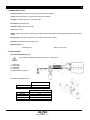
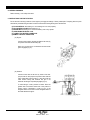
2.2.2 “SEAWATER” COOLING CIRCUIT (Fig. 2.2)
0) Bottom cock
1) Intake connection with water filter
2) Water pump
3) Water / Water cooler
4) Wet exhaust elbow
5) Gear box cooler
(ONLY SMI-R2 y SMI-R3 GEARBOX)
Fig. 2.2
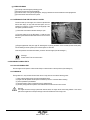
2.3 LUBRICATION CIRCUIT
2.3.1 ENGINE
Lubrication is forced with a lobe pumpand total filtration of the oil pumped tothe various lube points on the engine.The oil is forced
by the pump through acontrol valve to the filter, the enginemain bearings and, by way of external pipelines, to the rocker arms.
Also, read the heading 9.2.
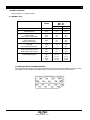
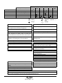
Oil circuit pressure (with hot engine):
min / 800 rpm = 1.0 bar
máx / 2600-3000 rpm = 2 - 4 bar
ENGINE
TYPE
MINI – 62
MINI – 62L
MINI – 62G
CAPACITY
(1)
5.5 liters
5.5 liters
5.5 liters
CAPACITY
(2)
6.5 liters
6.5 liters
6.5 liters
(1) without change oil filter (only change oil)
(2) Total capacity. When the oil and the oil filter are changed.
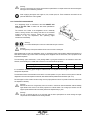
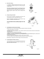
Fig. 2.3.1
(1) Valve push rod
(2) Valve mechanism
(3) Valve
(4) Pressure relief valve
(5) Piston
(6) Camshaft
(7) Main gallery
(8) Timing gear
(9) Oil pump
(10) Crankshaft
(11) Balancer shaft
(12) Oil filter
(13) Oil strainer
(14) Drain plug
2.3.2 GEARBOX
Gearbox has its own lubrication,independent from the engine.
Read its Service Manual.
ENG - 6
03917101.ENG rev. 1