1
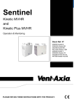
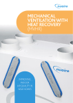
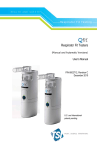
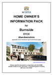
9041381- Issue 6 4/11
MODEL: DV72
Mechanical Ventilation with Heat Recovery
Installation Instructions and User Manual
Commissioning Data: to be completed by the installer
Date of installation:
Configuration
Left Hand
Right Hand
Product Serial No:
Important:
This multi speed unit requires Air Flow Rates to be adjusted
on installation
This manual must be kept by the householder
Index
1.
General
1
2.
Introduction
2
2.1.
General
2
2.2.
Fitting the HR in brief
2
3.
Installation
3
3.1
Mounting the HR unit
3
3.2
Important instruction
3
3.3
Connecting ducts
3
3.4
Connecting condensation drain
4
3.5
Electrical connections
5/6
3.6
Overview installation HR diagrams
7
4.
User Maintenance
8
4.1
Cleaning the filters by user
8
4.2
Cleaning the heat exchanger by user
9
5.
Technical specifications
10
5.1
Appliance data
10
5.2
Exploded view of the HR unit
11
SAP Appendix Q test results
Declaration of conformity
Warranty
12/14
15
16
1. General
To maintain a healthy indoor environment, closely controlled ventilation is essential. There are
many pollutants that will affect the indoor air quality: human body waste products in the shape of
CO2, dead skin, perspiration and moisture. Add to this the waste products of cooking (cooking
smells), showering (moisture), gases from building materials and the waste products of pets.
Without proper ventilation this would be the perfect environment for the growth of mould,
subsequent damage to the decoration and fabric of a home and to the health of its occupants.
The HR unit is fitted with two fans:
The exhaust fan ensures that warm, damp and polluted air as near as possible to the source
will be extracted. The exhausted air must be replaced with fresh air, so the heat recovery unit
has not only an exhaust fan but is also fitted with a supply fan and air filters.
The supply air, which in winter is colder than the inside air, is heated in the heat recovery unit
using the heat of the exhaust air by means of the heat exchanger. This heat exchanger has an
efficiency of 91%, so a minimum loss of heat takes place and the supply air temperature is at a
comfortable level.
In exceptionally cold weather or winter conditions it is possible that the exchanger may freeze
due to sub-zero, cold incoming air. In such circumstances temporarily turn off the unit to allow
the exchanger to thaw. If the problem persists an in-duct heater may be required (switch not
supplied).
The fans are low energy EC motors with a constant (100% adjustable) air volume.
The filters in the unit ensure that the fresh supply air is clean as it enters the home. Also the
extract air from the property is filtered to protect the heat exchanger from unwanted
contamination. These filters have to be cleaned every month, depending on the pollution. The
filters should be replaced annually or after a maximum of 3 cleaning cycles.
DO NOT switch off the unit – it is designed to run continuously. If the unit is switched off,
indoor pollutants and moisture levels may increase which results in becoming dangerous
to your health and damaging your home.
In the event of a power failure or the unit has been turned off, restart the unit at High
Speed. This MVHR unit has a soft start.
It is important to follow the advice in this user manual and correctly maintain the system
to ensure a healthy indoor environment.
1
2. Introduction
2.1 General
Duplexvent DV72 is a complete heat recovery unit to ensure optimum efficiency for your home.
The unit can easily be set up for left or right handed operation. This can be done by changing the
position of the condensation drain at the bottom of the unit. See figure 3 on page 4.
Using the stand-off feet, screws and plugs supplied, fit the unit vertically either in a kitchen
cupboard or on a wall.
As standard, the unit is delivered complete with a mounting plate, fitting instructions, fixing kit,
condensation discharge fitting and a five speed switch (3 x manual, 2 x external sensors).
2.2 Fitting the HR unit in brief
1. Dismantle the HR unit in accordance with Section 3 of this manual
2. Mounting plate: Mounted by means of stand-off feet, screws and plugs supplied, vertically.
Locate the hole positions, ensuring that there is enough space around the unit so that the
duct work and the condensation drain can be fitted
3. Reassemble the HR unit in accordance with Section 3 of this manual.
4. When the HR unit has been mounted, the ducting runs can be completed. Remember that
both ducts to and from outside will be fitted to one side of the unit and the ducts to and from
the home are attached to the other side of the unit. Also the condensation discharge under
the unit can be fitted at this stage, please see figure 3 for reference on which side it should
be fitted.
5. If an appropriate electrical supply is present, the installation can be completed when the
duct runs are completed.
For further information about the operation, adjustment and maintenance of the unit, read the
next pages carefully.
2
3. Installation
3.1 Mounting the HR unit
The mounting plate of the HR unit can be fitted directly to the wall or joists with the delivered
screws, plugs and stand-off feet. Ensure that there is enough space for the condensation fitting
and ducts to be connected. The position of the electrical power supply (an earthed wall socket or
fused switched spur) must not be mounted above or closer than 1m to a cooker where it could
be affected by excessive heat or moisture.
The unit is designed to be mounted in a 600mm wide cupboard or on a wall.
Make sure there is a free space at the front of the appliance for cleaning the filter and carrying
out maintenance on the appliance.
For horizontal installation please contact one of our technical sales representatives.
3.2 Important instruction
Installation of the appliance must be carried out by a qualified and suitably competent person in
accordance with all relevant Building Regulations, Health & Safety requirements and the fitting
instructions of the heat recovery unit. Installation should be carried out in clean, dry conditions
where dust and humidity are at minimum levels. This appliance is not suitable for outdoor
installation. IEE wiring regulations must be adhered to.
3.3 Connecting ducts
When the heat recovery unit has been installed the ducts can be fitted. The ducts to and from
the home are on one side of the unit. The ducts to and from outside are on the opposite side.
In order to prevent condensation on the outside of the exterior air inlet duct and the air outlet
duct, both ducts must be insulated.
It is recommended that insulated ducting to be used for the ducts to and from the appliance,
without placing any strain on the terminal or fixings.
Remember: When sizing the ducts try to ensure that the total resistance of the inlet as well as
the exhaust system does not exceed 100 Pascal.
3
A=
B=
C=
D=
E=
F=
No exhaust duct too close to
the air inlet
Inlet duct from roof
Outlet duct from roof
HR unit
Ducts from and to the house
Condensation drain with
U-bend (not supplied)
Fig 2: Connection example of Heat Recovery Unit
3.4 Connecting condensation drain
The condensation drain must be mounted at the bottom of the heat recovery unit with the fitting
supplied. Use a 20mm hole saw to cut out the bung, taking care to cut on the correct side of the
unit according to left or right handed configuration. Avoid damage to the mains cable. Use silicon
to seal the condensation fitting to the back half of the HR unit.
The drain must discharge into the household drainage system or directly to outside. Take care
that the distance between the unit and U-bend will be enough for de-mounting and cleaning.
Important Note: The drain must incorporate a U-bend to prevent air penetration.
Condensation drain: 22mm standard PVC
Vertical Position
Left
Right
Figure 3: Connection of HR unit to drain pipe
4
Important Note: The unit can be mounted horizontally only with an additional condensation kit.
For more information please contact one of our sales representatives.
3.5 Electrical connections
The appliance must be earthed. All wiring must confirm to BS 7671: Latest edition IEE wiring
regulations.
This appliance is suitable for 230v ~ 50Hz single phase supply fused at 3 amps.
This appliance is supplied with a mains flexible cable (PVC sheathed, 6-core 0.75mm2).
A double pole switch having a minimum contact separation of 3.0mm must be used to provide
isolation for the unit.
Switch Positions
Function
Low
(R1 / Low)
100% adjustable
Medium
(R2 / Med)
100% adjustable
High
(R3 / High)
100% adjustable
Remote Switch Positions
(R4)
100% adjustable
(R5)
100% adjustable
Upon installation the fan should be started in High Speed mode to ensure optimum performance
of the fans and switched to the required continuous ventilation setting.
The fan speed control must not be mounted above or closer to 1m to the cooker where it could
be affected by excessive heat or moisture.
Wiring diagram
A five speed control switch (3 x manual, 2 x external sensors) is supplied. Each fan speed must
be adjusted to suit dwelling on installation (R1-Low/R2-Med/R3-High).
Any optional external sensors, i.e.: CO2, Humidity, Timer/Clock, Motion/PIR must also be
adjusted when connected (R4, R5).
5
Suggested set points are shown for general purpose ventilation (trickle, medium, purge) which
enable manual boost for purge (maximum) ventilation and/or override of external sensors when
fitted.
Figure 4: Electrical Diagram
6
3.6 Installation diagram/Mounting the unit
6
1. Pull the green front cover off the six Velcro fixings.
2. Place the unit flat on the floor and unscrew and keep safely the four stud retaining screws.
3. Without damaging the rubber seal separate the moulded top half of the unit from the bottom
half by pulling the casing straight forward.
4. Unscrew the four forward protruding studs and keep safely.
5. Stand unit upright to separate the metal wall mounting plate from the bottom half of the casing.
Pull the casing forward leaving the rear protruding studs attached to the metal backplate.
6. Secure the metal base plate with the rear studs still attached to the wall
7. Re-assembly of the unit to the wall mounted backplate with the protruding studs is the reverse
of the removal procedure
7
4. User Maintenance
User maintenance is limited to periodically cleaning the filters and the heat recovery cube. The
unit should not be used without filters.
4.1 Cleaning the filters by user
1
2
Switch off the power supply
Remove front panel
Remove filter covers
Remove the filters
3
4
Vacuum the outside of the filter
After cleaning replace filters
at same side
5
Replace filter covers and front panel
Always ensure that the date is recorded
on the back of the front panel
8
4.2 Cleaning the heat exchanger by user
1
2
Important: Switch off the power supply
Remove front panel
Unscrew the 4 screws on the front
of the unit.
Remove the front half of the unit
3
4
Remove the heat exchanger
Clean the heat exchanger with warm
soapy water
Use a sterilizing agent to sterilize
Reassemble the unit taking care
not to damage the rubber seals
The fans must be cleaned if they are dirty. Be sure not to bend the blades of the fan since this
could cause a motor imbalance, unnecessary noise and will shorten the life of the motor
bearings. To expose motors, follow the above instructions and vacuum out where necessary.
We recommend that this is done at the same time as cleaning the heat exchanger.
9
5. Technical specifications
5.1 Appliance data
Switched
External sensor
Low /
R1
Middle /
R2
High /
R3
R4
R5
Max
Typical Ventilation Settings [m /h]
54
140
280
97
75
280
Rated power [W]
10
42
150
20
14
150
EC Fan Speed settings selected on installation
(100% adjustable)
3
3
Permissible duct/system resistance [Pa]
100 Pa at 200 m /h
Maximum flow (Free Discharge)
280 m /hr (78 l/sec)
3
0-100% adjustable on each speed.
Set on installation
Low and Medium flow and optional sensor inputs
Dimensions (w x h x d) [mm]
560 x 635 x 260
Ø125
Duct diameter [m]
External diameter condensate discharge [mm]
22
Filter class
EU3
Weight [kg]
14 kg
Supply voltage [V~/Hz]
230v / IPh / 50Hz
Power (watts)
Maximum 150w
Protection degree
IPX2
Thermal efficiency up to (up to %)
91%
Fan air performance graph
10
5.2 Exploded view of the HR unit
Please refer to guarantee terms for repair/replacement within the guarantee period. After expiry
of the guarantee when ordering parts, be sure to mention the article code number (see exploded
view), the type of heat recovery appliance, serial number, production year and the name of the
part:
Example
Appliance type
Serial number
Year of production
Part No
: DV72
:
: 2010
: 9041322
Part required
Replacement Filters (2)
: 9041511
Type and serial number are printed at the identification plate on the top of the inner assembly.
Parts List
Nr
Article description
1
2
3
4
5
6
7
8
Back Plate
EPP Mouldings
Condensation Drain
EC Fans
Heat Recovery Cell
Filters (9041511 pack of two)
Filter Covers
Front Plate
11
SAP Appendix Q Testing Results
Central mechanical supply and exhaust ventilation system packages with
heat recovery used in a single dwelling
Brand Name
Airflow
Model
Duplexvent DV72
Model Qualifier (if applicable)
Name
Address
Current Manufacturer
and Contact Details
Airflow Developments Ltd
Lancaster Road
Cressex Business Park
High Wycombe
HP12 3QP
Telephone
01494 525252
Website
www.airflow.co.uk
Original Manufacturer (if different)
First Year of Manufacture
2010
Last Year of Manufacture
Testing Body
BRE
Date of test
22/03/2010
Serial Number of Product Tested
5780 EC
150 & 125 mm diameter rigid
plastic and 200 mm diameter
rigid plastic
150 & 125 mm diameter rigid
plastic and 200 mm diameter
rigid plastic
MVHR to outside grille duct types and
size
Duct types and sizes used for supply
and exhaust
Results of leakage tests
Table Q1
Internal
Pass
External
Pass
12
Results for SAP calculations (at minimum flow rate condition)
This product has only been tested with rigid ductwork and the data are not applicable for SAP
calculations if installed with flexible ductwork.
Table Q2 – Systems with rigid ductwork only
Exhaust
terminal
configuration
Kitchen +
1 additional wet
room
Kitchen +
2 additional wet
rooms
Kitchen +
3 additional wet
rooms
Kitchen +
4 additional wet
rooms
Kitchen +
5 additional wet
rooms
Fan
speed
setting
Specific
fan
power
(W/l/s)
Heat
exchange
efficiency
(%)
Energy Saving
Trust Best
Practice
Performance
Compliant
100%
Variable
0.73
91
Yes
100%
Variable
0.72
90
Yes
100%
Variable
0.79
89
Yes
100%
Variable
0.93
88
Yes
100%
Variable
1.06
87
No
These figures are entered into either:
(a) In the case of SAP software amended to SAP 2005 version 9.81 allowing direct entry of
MVHR data, the SAP software, or
(b) In the case of SAP software amended to SAP 2005 version 9.81 not allowing direct entry of
MVHR data, the SAP Q MVHR Calculation Spreadsheet v9.81 and the results from the
spreadsheet into the Special Features part of the SAP 9.81 software, or
(c) In the case of SAP software to SAP 2005 version 9.80 , the SAP Q MVHR Calculation
Spreadsheet v9.80 and the results from the spreadsheet into the Special Features part of the
SAP 9.80 software. They must NOT be entered directly into SAP 2005 version 9.80 software
13
Table Q3 – Systems with flexible ductwork only
Exhaust terminal
configuration
Kitchen +
1 additional wet
room
Fan
speed
setting
Specific
fan
power
(W/l/s)
Heat
exchange
efficiency
(%)
Energy Saving
Trust Best
Practice
Performance
Compliant
N/A
N/A
N/A
N/A
These figures are entered into either:
(a) In the case of SAP software amended to SAP 2005 version 9.81 allowing direct entry of
MVHR data, the SAP software, or
(b) In the case of SAP software amended to SAP 2005 version 9.81 not allowing direct entry of
MVHR data, the SAP Q MVHR Calculation Spreadsheet v9.81 and the results from the
spreadsheet into the Special Features part of the SAP 9.81 software, or
(c) In the case of SAP software to SAP 2005 version 9.80 , the SAP Q MVHR Calculation
Spreadsheet v9.80 and the results from the spreadsheet into the Special Features part of the
SAP 9.80 software. They must NOT be entered directly into SAP 2005 version 9.80 software
Results for Approved Document F (at maximum flow rate condition)
Table Q4
Fan speed
setting
Total
exhaust flow
rate
(l/s)
Total supply
flow rate
(l/s)
Kitchen +
1 additional wet room
100%
Variable
15.0
15.0
Kitchen +
2 additional wet rooms
100%
Variable
21.0
21.0
Kitchen +
3 additional wet rooms
100%
Variable
27.0
27.0
Kitchen +
4 additional wet rooms
100%
Variable
33.0
33.0
Kitchen +
5 additional wet rooms
100%
Variable
39.0
39.0
Exhaust terminal
configuration
Comments
Only figures from Table Q2 or Table Q3, not both, should be used with the SAP Q Calculation
Spreadsheet for this technology type.
Table Q4 results are only applicable for Approved Document F requirements.
14
Declaration of Conformity
We declare that the equipment detailed below conforms to the requirements of the EC council
directives relating to electromagnetic compatibility and safety of electrical equipment.
Equipment type:
The Heat Recovery Appliance Model: DV72
Supplied by
Airflow Developments Limited
Aidelle House, Lancaster Road
Cressex Business Park
High Wycombe
Buckinghamshire
HP12 3QP
T: +44 (0) 1494 525252
Visit: airflow.com
Description of equipment:
Mechanical Heat Recovery Ventilation Unit
Relative EC Council Directives:
2004/108/EC (EMC)
2006/95/EC (LVD)
Applied Harmonised Standards: EN 60335-1:2002/A2:2006
EN 60335-2-80:2003/A1:2004
BS EN 308:1997
EN13141-7:2004
Airflow Developments Limited warrants that heat recovery appliances are manufactured from
high quality materials and that continuous quality control ensures that they comply with the
above directive.
15
Warranty
This product has a warranty period of two years. The warranty can be upgraded to THREE years
from the date of purchase against faulty material or workmanship by registering on our web site
at www.airflow.com
The warranty covers the product only and not the installation cost.
In case such a fault in the manufacture becomes apparent during the Warranty Period, Airflow
may, at its absolute discretion, repair the product free of charge or refund the cost of the product
AS LONG AS AND ONLY IF:
1. The product is returned within the Guarantee Period with evidence of purchase date
2. The product has not been misused or handled carelessly or used on an inappropriate
voltage supply
3. Repairs have not been attempted other than by Airflow’s service staff or
4. In Airflow’s sole discretion, the product is found to be faulty. If it were not found to be
faulty, the product would be available for collection from the relevant Airflow premises
within one calendar month and if it was not collected, it would be subsequently
delivered by Airflow and a delivery charge will be made.
5. Has been installed in accordance with the latest Building Regulations and IEE Wiring
Regulations.
This warranty does not confer any rights other than those expressly set out above and does not
cover any claims for consequential loss, damage or any costs incurred in the replacement of the
faulty product.
This warranty is offered as an extra benefit and does not affect your statutory right as a
consumer.
All information believed correct at time of going to press.
All goods are sold according to Airflow Developments Limited’s Standard Condition of Sale
which is available on request.
In the interest of continuous development Airflow Developments Limited continuously strive to
improve their products and reserve the right to change specifications and prices without prior
notice.
©Copyright 2011. Airflow Developments Ltd
Airflow Developments Limited
Aidelle House, Lancaster Road
E-mail: [email protected]
Cressex Business Park, High Wycombe, Telephone: +44(0) 1494 525252
Buckinghamshire. HP12 3QP. U.K
Facsimile: +44(0) 1494 461073