1
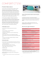
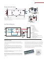
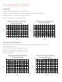
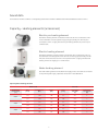
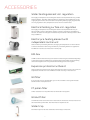
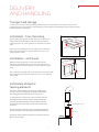
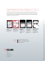
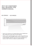
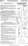
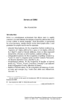
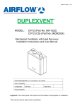
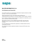
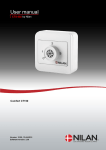
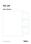
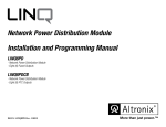
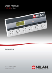
ProduCt data Comfort CT150 by nilan Ventilation & passive heat recovery Domestic Passive heat recovery Ventilation < 175 m3/h Comfort CT150 Product description Comfort CT150 is an energy-efficient ventilation system with heat recovery. This system is designed for use in residential homes with a ventilation requirement of up to 150 m3/h. Comfort CT150 is ideal for new and refurbished flats, terraced housing and holiday cottages, where there is limited space and a focus on maintaining an optimal indoor climate. If you wish to save on the cost of ducting and reduce heat and pressure loss in the duct system, Comfort CT150 is ideal used as a decentralised system, for example, if you fit two systems into one large residential housing unit. Comfort CT150 is supplied as standard with G4 filters, a counterflow heat exchanger in either polystyrene or aluminium (both high-efficiency solutions), a fully automatic bypass damper, a CTS 602 control unit and efficient EC fans. The fan rotation is constant and can be adjusted in four steps. You can opt for a system with a display or a stepwise adjustable control panel. The system has an integrated automatic defrosting feature and filter change indicator (filter change indicator only available with display). Standard unit Comfort CT150 is serviced from the front. Filters are easily replaced by opening the top of the front of the unit using two thumbscrews. Condensate which may form in the heat exchanger is transported away via the condensation drain. The drain must be fitted with water trap and frost protection if the system is installed in a cold place outside the building envelope of the home. Comfort CT150 is supplied tested and ready for use. Installation and commissioning must be carried out by a certified electrician or plumber. Technical specifications Comfort CT150 includes the following as standard: • G4 filters • Fully automatic 100 % bypass damper Dimensions (B×D×H) 1,000 × 524 × 333 mm Weight (*1) 28/30 kg • Constant volume EC fans Plate type housing • Polystyrene or aluminium counterflow heat exchanger Heat exchanger type • Humidity sensor Aluzinc steel plate, white powder coating, RAL9016 Counterflow heat exchanger, polystyrene or aluminium Fan type EC, constant volume Filter class Standard G4 Duct connections Ø 125 mm Condensation drain PVC, Ø 20 ×1.5 mm External leakage (*2) <1.38 % Internal leakage (*3) <1.82 % Comfort CT150 can be ordered with the following accessories: Supply voltage 230 V (±10 %), 50/60 HZ • Water heating element with adjustmnt valve and frost protection (duct-mounted) *1 Max. input/power (*4) 54 W/0.25 A Tightness class IP31 • Electrical pre-heating element (duct-mounted) Standby power 3W • Options PCB for CTS 602 control unit Power consumption (*4 & 5) 195 kWh/year Ambient temperature -20/+40 °C • Filter monitor with timer (only available with display) • Fitting brackets: Universal set including wall and ceiling brackets • CTS 602 control system with either display or stepwise adjustable control panel Accessories • Electrical heating element (duct-mounted) • Plate filter (G4) • Pollen filter (F7) • Duct filter G4, initial filter for F7 • Water trap with odour lock and vacuum valve The above electrical accessories can be connected to the CTS 602 control. * 1 Weighs 30 kg with aluminium heat exchanger * 2At ± 250 Pa and 126 m3/h in compliance with EN308/EN13141-7. * 3At ± 100 Pa and 126 m3/h in compliance with EN308/EN13141-7. * 4 Power uptake with heating element (optional extra). * 5Electricity consumption on continuous operation for system with SEL value of 800 J/m3 and 100 m3/h. * 1 Download of relevant software is required to control heating element 2 4 Comfort CT150 by nilan 1 4 3 2 4 3 Dimensional drawing 1 1 4 3 1 1 4 2 5 2 4 3 5 5 1 1 3 All dimensions are in mm. 4 Comfort CT150 shown with access 2 to the primary side (heat exchanger) and connection to the right side. 5 3 1 4 11 2. Functional diagram 5 11 2. 6 3. 1. 4. 4. 1 T10 T3 T8 3 3. T2 T4 4 T9 T7 TC 1 3 1. 2 1. 2. 3. 1:Fresh 2. air 4. 2: Supply 3. air 3: Extract 4. air 4: Discharge air 5: Condensate drain 6: Electrical connection 2 3 Automation Nilan A/S Nilanvej 2 8722 Hedensted 2 1. 1 T2/T7: Supply air sensor T3: Extract air sensor T4: Discharge air and defrost sensor Tlf: 76 75 25 00 Fax: 76 75 25T8:Fresh 25 air sensor www.nilan.dk T9: Heating element (frost protection) T10:Room sensor Nilan A/S Nilanvej 2 8722 Hedensted 5 2. 2 Connections 3. 2 3 1 2 3 Tlf: 76 75 25 00 Fax: 76 75 25 25 www.nilan.dk 4 Control units Comfort CT150 is controlled4 using the CTS 602 control unit 3 which can be controlled via a display or via a stepwise adjustable control panel. The control panel must be placed in a dry and frost-free place at least 1.5 m above floor level and at least 0.5 m from any corner. Avoid placing the panel on an external wall or in direct sunlight. The display panel offers a wide range of different functions, including menu-controlled operation, weekly program settings, timer-controlled filter flow meter, fan speed adjustment, summer bypass (free cooling), heat element control, error messages, etc. Operating instructions for CTS 602 using either a display or stepwise adjustable control panel can be found in a separate user manual supplied with the unit. The stepwise-adjustable control panel facilitates adjustment of fan speed at four different levels. The control panel is factory set. The factory settings are basic settings, which can be customised to match operational requirements and thus achieve optimal operation and utilisation of the system. 3 4 Planning data Capacity Maximum Pa capacity of standard system, pt,ext as a function of qv SFP values according to EN13141-7 are for a standard system with G4 filters and no heating element. SFP values comprise the unit’s total power consumption incl. control. Conversion factor: J/m3 = 3600×Wh/m3 = 3600×W/m3/h. Aluminium counterflow heat exchanger 400 400 350 350 300 300 250 250 200 Max Pa 150 1200 J/m3 100 Max Pa 200 150 1200 J/m3 100 1000 J/m3 50 0 pt, ext [Pa] pt, ext [Pa] Polystyrene counterflow heat exchanger 1000 J/m3 50 800 J/m3 0 50 100 150 200 0 250 800 J/m3 0 50 100 150 200 250 qv [m3/h] qv [m3/h] Temperature efficiency Temperature efficiency for system with counterflow exchanger according to EN 308 and EN13141-7 for supply air. Temperature efficiency EN 308 t = (tsupply air-tfresh air)/(textract air-tfresh air) corrected for fan heat Temperature efficiency EN13141-7 supply air (fresh air 7 °C) t = (tsupply air-tfresh air)/(textract air-tfresh air)*(qm supply air/qm extract air) qm is the volume air flow. Polystyrene counterflow heat exchanger Aluminium counterflow heat exchanger 0,96 0,96 0,94 0,94 0,92 0,92 EN 13141-7 0,90 EN 308 0,88 ηt [%] ηt [%] 0,90 0,88 0,86 0,86 0,84 0,84 0,82 0,82 EN 13141-7 0,80 90 100 110 120 130 140 0,80 150 qv [m /h] EN 308 90 100 110 120 qv [m3/h] 3 4 130 140 150 Comfort CT150 by nilan Sound data Sound data for Comfort CT150 is currently being tested and accredited. Validated data will be available at the end of 2013. Capacity – Heating elements (accessories) Electric pre-heating element The electric heating element is installed on the fresh air duct at a distance of min. 2 x duct diameter from the system’s supply air pipe (usually min. 250 mm) and connected to a 230 V supply. The elcetric pre-heating element can produce up to 1.8 kW of heat. Electric heating element The electrical heating surface is fitted in the air inlet duct at a distance of min. 2 x duct diameter from the system’s fresh air inlet connecting pipe (normally min. 250 mm) and connected to the CTS 602 control panel and 230 V supply. The electrical heating surface can supply up to 0.9 kW of heat. Water heating element The water heating element is installed in the supply air duct and must be connected to the primary heat supply. Capacities can be seen in the table below. Capacity water heating element Water side Temperature forward/back [°C] Air side Flow [m3/h] Pressure drop [kPa] Output [kW] Flow [m3/h] Temperature after WHE * [°C] Pressure loss over element* [Pa] 0.04 0.85 0.52 100 31.1 2 0.06 1.25 0.64 135 29.8 3 0.04 0.69 0.94 100 43.5 2 0.05 1.00 1.16 135 41.1 3 0.03 0.40 1.06 100 47.0 2 0.04 0.58 1.30 135 44.2 3 40/30 60/40 70/40 * Water heating element. 5 accessories Water heating element incl. regulation The supply air temperature can always be raised to the required level using a water heating element. The water heating element is designed to be installed next to the supply air pipe and must be connected to the primary heating supply. Supplied with two-way regulation valve, temperature sensor and frost thermostat. Electrical heating surface incl. regulation The supply air temperature can always be raised to the required level using an electric heating surface. The electric heating surface is supplied for installation in the duct set at the fresh air pipe and has the required sensors already fitted to allow easy installation. Electric pre-heating element with independent control unit With an electric pre-heating element, the supply air temperature can be increased to reduce the need for defrosting. The electric pre-heating element is supplied for installation in the duct set next to the fresh air pipe. EM-box An EM-box allows heat recovery from the air from the range hood and thereby helps to heat the supply air. The EM-box is equipped with a special filter which efficiently cleans the range hood air of fat particles and thereby protects the system. Expansion printed circuit board With an expansion printed circuit board, the features of the CTS 602 control unit are expanded to include control of an EM box for heat recovery on the extractor. G4 filter If you choose not to fit a pollen filter, you can fit a G4 filter to the system instead. The filter filters fresh/extract air. F7 pollen filter A filter cassette for an F7 pollen filter can be fitted in the system . G4 duct filter An Ø125 duct filter can be mounted in the fresh air and extract air ducts if the unit is also fitted with a pollen filter. The filter filters fresh/extract air. Water trap The water trap ensures that condensate flows freely from the unit. 6 Delivery and handling Comfort CT150 by nilan Transport and storage Comfort CT300 comes in factory packaging that protects it during transport and storage. Comfort CT300 must be stored in a dry place in its original packaging until installation. The packaging should only be removed immediately prior to installation. Installation – from the ceiling When installing the system from the ceiling, future service and maintenance should be taken into account. We recommend a minimum gap in front of the system of 60 cm and 50 cm to both sides. The unit must be installed level for the sake of the condensate drain. The condensate drain requires clearance of min. 20 cm under the drain nozzle. Min. 50 cm Min. 60 cm Min. 50 cm Min. 20 cm Installation – on the wall When mounting the system on a wall, future service and maintenance should be taken into account. We recommend a minimum gap in front of the system of 60 cm and 50 cm to both sides. Min. 50 cm Min. 60 cm Min. 20 cm The unit must be installed level for the sake of the condensate drain. The condensate drain requires clearance of min. 20 cm under the drain nozzle. Installation of electric heating elements The electric heating element (accessory) is installed after Comfort CT300 in the supply air duct itself and the electric pre-heating element (accessory) in the fresh air duct. Ô A safety distance of a minimum of 15 cm must be observed between the electric heating element and any flammable material. The heating element must be insulated with fireproof insulation material. The connection box should not be insulated. Electric heating element The distance before and after the electric heating element to another component must be at least twice the duct diameter. Min. 25 cm The electric heating element must be connected by a certified electrician or plumber. 7 Information from A to Z Nilan develops and manufactures premium-quality, energy-saving ventilation and heat pump solutions that provide a healthy indoor climate and low-level energy consumption with the greatest consideration for the environment. In order to facilitate each step in the construction process – from choosing the solution through to planning, installation and maintenance – we have created a series of information material which is available for download at www.nilan.dk. VENTILATION = WELL-BEING COMFORT BY NILAN 2 1 PRODUCT DATA 4 COMFORT CT150 BY NILAN 4 3 3 1 3 1 4 2 2 5 5 1 2 4 3 1 2 4 3 11 1 4 1 3 2. 2 3 1 4 1 4 2 1 3 2 1. 4. 2. 4. 5 11 11 Ventilation & passive heat recovery 2. 4. Ventilation with heat recovery 1. 2. 2. 3. Passive heat recovery Ventilation < 150 m3/h 1. 3. 1 2 3 Nilan A/S Nilanvej 2 8722 Hedensted Brochure Product data General information about the solution and its benefits. Technical information to ensure correct choice of solution. www. NILAN .dk Installation instructions Detailed guide for installation and initial adjustment of the solution. User manual 1 2 3 4 Detailed guide for regulation of the solution to ensure optimum day-to-day operation. 1. 4. Nilan A/S Nilanvej 2 8722 Hedensted 4. Domestic 2 5 1. 3. Healthy indoor climate all year round 3 1 4 3. 5 5 2. 3. Tlf: 76 75 25 00 Fax: 76 75 25 25 www.nilan.dk 3. 4. 1. 4 Nilan A/S Nilanvej 2 8722 Hedensted Tlf: 76 75 25 00 Fax: 76 75 25 25 www.nilan.dk Drawing material 1 2 3 Nilan A/S assumes no responsibility for any errors or omissions in the printed information material or for loss or damage that may follow from the use of such published materials - whether such loss of damage is caused by errors or inexpediencies in the material or otherwise. Nilan A/S reserves the right without prior notice to change products and information material. All trademarks are the property of Nilan A/S. All rights reserved. 1 Tlf: 76 75 25 00 Fax: 76 75 25 25 www.nilan.dk 4 Nilan is happy to make 2D CAD drawings available for planning with the solution. Visit us at www.nilan.dk to find out more about our company and solutions, download further information and find your nearest dealer. Ver. 1.0 Nilan A/S Nilanvej 2 8722 Hedensted Denmark Tel. +45 76 75 25 00 Fax +45 76 75 25 25 [email protected] www.nilan.dk