1
INSTALLATION
INSTALLATION
n
n
INDOOR UNIT
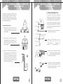
Connecting of cables
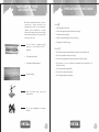
1. Open the front panel
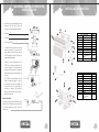
1. Fitment of mounting plate
Electrical box cover
2. Dismentle the electric box cover
The mounting plate should be fitted on the structural part of wall on which indoor unit
is to be installed.
Indoor unit
terminal
and fastener
Screw
3. Connect the cable
2. Drill two holes at a distance of 450 mm between them for the expansion bolts.
4. Reassemble the fastener and electric
fasten string at the central hole
at least
B from top
C or more
A or more
Diagram
box cover.
Fastener
Screw
from sidewall
from sidewall
Connecting cable
Indoor unit terminal
mounting
plate
Pull the Connecting cable’s
wire in completely
Connecting cable
plumb
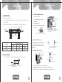
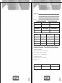
n Installation of indoor unit
Model
1.0 T
1.5 T
A
175
175
After putting the pipe assembly through
the wall, attach the indoor unit to the
mounting plate on the wall as shown in
the figure.
Dimensions in mm
C
B
260
245
260
245
Mounting Plate
Indoor unit
Rib of indoor unit
Bottom
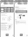
n Installation of outdoor unit
Connect diagram
Outdoor unit terminal
n
Drill on the wall
Indoor unit terminal
Connecting
cable
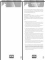
Confirm the position of holes and drill holes of diameter 65 mm on the wall
Connecting
cable
White
Blue
180mm
Yellow/Green
Outdoor unit terminal
18
10
Insert Ruler
• The connecting cables must be clipped together.
Center of Hole(Ø65mm)
Align Ruler with straight line
• Special cable to be used to connect indoor unit and outdoor unit.
• The electric box cover must be mounted on its position on outdoor unit.
16
17