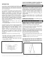
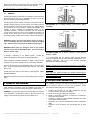
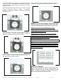
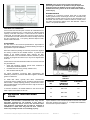
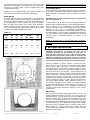
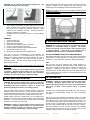
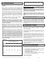
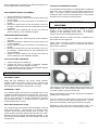
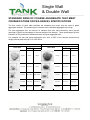
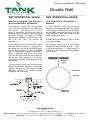
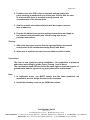
1
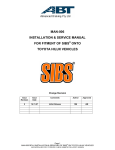
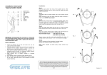
Fibreglass Double Wall Tanks Liquid Filled Interstice INSTALLATION MANUAL Tank Solutions Pty Ltd ABN: 59 142 807 949 513 Tomago Road, TOMAGO NSW 2322 PO Box 102, RAYMOND TERRACE NSW 2324 Ph +61 2 4964 8270 e-mail [email protected] Tank Solutions Fibreglass Single & Double Wall Tank Installation Manual Form F 938 Revision A Page 1 of 14 If you have any questions or encounter any situations not covered in these installation instructions, contact the Tank Solutions Technical Service Department on (02) 4964 8270. INTRODUCTION It is important to follow the procedures and instructions in this manual in order to safely and properly install a Tank Solutions Underground Storage Tank. Failure to follow these instructions will void the tank warranty and may cause tank failure, serious personal injury, or property damage. The Tank Solutions warranty applies to a tank installed according to these instructions. Since Tank Solutions does not control the parameters of any installation, our sole responsibility in any installation is that presented in our warranty. Use the Tank Installation Checklist, accompanying this manual, as the installation proceeds. Retain a copy of the checklist, along with any deviation – authorisation letters, certification etc. in your files and return the original to Tank Solutions. For Warranty to be effective, the completed Installation Checklist must be returned to Tank Solutions within 30 days (refer to Installation Checklist for more details). Consult your Tank Solutions representative or distributor for a supply of additional checklist forms. Comply with all applicable regulations and standards, such as: • national, state and local construction, health, safety and environmental codes • industry standard practices (eg. PEI/RP100, API RP1615 & EPA, CP-4, AS1692, AS1940) For additional information, contact your state and local government authorities, including health, fire or building departments, and environmental agencies. All work must be performed according to standard industry practices and OH&S regulations. A Tank Solutions requirement will never take precedence over a requirement imposed by any federal, state or local code or regulation. In all cases, any such requirement takes precedence over any provision of the Tank Solutions manual. Tank Solutions must authorise any variation to, or deviation from, these instructions. This authorisation must be made in writing, prior to tank installation. DEFINITIONS: Throughout this text, these definitions will apply: • Socket fitting: a fitting, either on a manway or on the tank shell, which opens into the primary containment vessel, where the tank’s contents are normally stored; • Monitor fitting: a fitting, located on the tank shell, which opens into the secondary containment vessel, which is the normal monitoring location on the tank. For additional terminology, see Figure 0-1. SAFETY Before beginning the tank installation, read through the entire installation manual. It is the installer’s responsibility to comply with all safety precautions, codes and regulations. No instructions or procedures presented in this manual should be interpreted as to put as risk any person’s health or safety or to harm any property or the environment. Keep the Installation Manual available at the installation to refer back to safety procedures as needed. The following definitions will serve as a guide when reading the Installation Manual: WARNING: indicates hazards which, if not avoided, could cause death, serious personal injury or significant property damage. CAUTION: indicates hazards which, if not avoided, may cause personal injury or property damage. 1. PREPARATION FOR INSTALLATION WARNING: Working in excavations is dangerous and is regulated by safety codes. Careless activity or operation of equipment can cause death or serious personal injury. Although the corrosion-resistant Tank Solutions tanks are rugged, care must be taken that they are not dropped or damaged during delivery, unloading and handling on the job site. WARNING: The tanks are heavy and have a large surface area. The tanks will roll on sloped surfaces and can be blown about by the wind. Uncontrolled movement of the tanks can cause death, serious personal injury and property damage. Before the tanks are unloaded or relocated on the job site: • Be sure that all equipment used to lift the tanks is rated to handle the load. • Prepare the unloading and/or storage site by removing all rocks and debris. • Arrange for sandbags or tyres to be used as chocks. Use the lifting lug(s) when hoisting the tank. Do not wrap chain or cable around the tank. Tanks larger than 45,000Litres have multiple lifting lugs. Use all of the lugs to move the tank. (See Fig. 1-1). Use guy ropes to guide the tank when needed. Do not move the tank by rolling. FIGURE 0-1 FIGURE 1-1 Tank Solutions Fibreglass Single & Double Wall Tank Installation Manual Form F 938 Revision A Page 2 of 14 Whenever the tanks are stored at the site, chock them in place to prevent rolling. Tie them down if high winds are expected. 20mm 10mm 2. PREINSTALLATION TEST 2.1 GENERAL Tank Solutions tanks are tested prior to shipment, but the tank must be checked at the site prior to installation in order to verify the absence of shipping and handling damage. Visually inspect the tank exterior and interior of the primary tank for damage and the presence of blue marker dye including external shell of the tank or on the tray of the vehicle. Any damage should be documented and Tank Solutions contacted immediately. If no damage is found, complete the appropriate section on the Installation Checklist. The Brine level should also be checked at this point. Record the brine level on the Installation Checklist. It is normal for the brine level to drop somewhat during transport, however if no brine is visible in the monitor, contact Tank Solutions. Pea Gravel PEA GRAVEL: Mix of rounded particles – sizes between 10mm and 20mm. 14mm 10mm WARNING: Always secure the tank before moving or lifting it. This is commonly done by connecting a crane to the lifting lugs. Failure to do so could result in death or serious injury. WARNING: While moving or lifting the tank, do not position any part of your body underneath the tank. This could result in death or serious injury. If damage is detected, do not attempt repairs. Contact the Production Manager at Tank Solutions on (02) 4964 8270. After installation and before backfilling to grade, testing must be repeated to verify that no damage has occurred during installation. Remove all temporary service fitting plugs and the reservoir fitting plug. Check the monitoring fluid level in the reservoir. It should be about ½ full. Visually check the interior of the tank for monitoring fluid. There should not be any. Replace the protective covers in the service fitting and the reservoir fitting. Crushed Stone CRUSHED STONE: Mix of angular particles – sizes between 10mm and 14mm. It is recommended that the supplier certify that the material conforms to AS2758 and any other applicable specifications. (For additional information, refer to the Tank Solutions pamphlet Fibreglass Tank Backfill Guidelines). NOTE: If material which meets these specifications is not available, contact the Tank Solutions Technical Service Department for information on approved alternate materials and installation instructions. Using other than approved bedding and backfill materials without Tank Solutions prior written approval will void the tank warranty and may result in tank failure. 4. EXCAVATION PARAMETERS 3. BACKFILL AND BEDDING Tank Solutions recommends tanks be installed using either pea gravel or crushed stone which meets the following specifications. GENERAL: The material is washed and free flowing and confirms to the specification of AS2758 and AS1141. No more than 5% (by weight) of the material may pass through a 2.36mm sieve. The installing contractor must take all precautions necessary to protect employees working in or near a tank excavation. These precautions should include, but are not limited to: • • • • • • Tank Solutions Fibreglass Single & Double Wall Tank Installation Manual Form F 938 Location and protection of any utility installations near the excavation before opening the excavation; Means of securing the walls of the excavation; Means of preventing exposure of employees to hazardous fumes from the excavation; Protection of employees from hazards associated with water accumulation in the excavation; Barricades, etc. to prevent unauthorised vehicle or pedestrian traffic; Inspection of the excavation and surrounding area at least daily. Revision A Page 3 of 14 The minimum depth of the excavation is normally determined by the presence or absence of groundwater and the presence or absence of traffic at the site. These dimensions are critical to the successful installation of a tank. Tanks in high water areas not subjected to traffic loads must have a minimum of 1 Metre of backfill covering and must be anchored. Tanks subjected to traffic loads must have a cover depth of at least 450mm of backfill plus 230mm of asphalt. An acceptable alternative is a minimum of 450mm of backfill plus 150mm of reinforced concrete. WARNING: In a non traffic installation, ensure that the areas above the tanks will never be subject to traffic load, which could cause tank damage and result in death or serious injury. NOTE: These depths of cover are MINIMUMS in all cases. NOTE: Asphalt and concrete pads must extend a minimum of 300mm beyond tank in all directions. Tanks subjected to traffic loads and high water must have a minimum of 760mm of backfill and either 230mm of asphalt or 150mm of reinforced concrete and must be anchored. NOTE: Maximum burial depth is 2.1m of cover over top of tank. NOTE: Manway riser (if present) must not transmit load from the slab to the tank. There must be a minimum 150mm space between the bottom of the slab and the top of the riser. 5. TANK SPACING NOTE: These are minimum spacings and must be increased as needed to accommodate deadmen or anchor slabs. Refer to Section 6 on tank anchoring. Always allow sufficient clearance to allow the deadmen to be set outside of the tank shadow. The relevant Australian Standard (AS1940) specifies the minimum tank separation distances. Tanks not subjected to traffic loads must have a minimum cover depth of 600mm of backfill, or 300mm backfill plus 100mm of reinforced concrete or 150mm of asphalt. STABLE SOIL CONDITIONS Where shoring is not required to maintain a vertical wall from top to bottom of the excavation, the minimum spacing between the sidewall or endcap of the tank and side of excavation must be 450mm. If more than one tank is to be installed in the same hole, there must be at least 450mm between the tanks. Tank Solutions Fibreglass Single & Double Wall Tank Installation Manual Form F 938 Revision A Page 4 of 14 WARNING: Only use the anchor points when lifting and positioning the deadmen. A spreader bar may be required to lift longer sections of deadmen. Use guy ropes to guide the deadmen when lifting. Failure to do so could result in death or serious injury. DEADMAN ANCHOR A deadmen is a reinforced concrete beam with a total length 300mm greater than the overall length of the tank. A deadmen may be fabricated in multiple sections as long as the total length is not decreased and each section contains at least two anchor points. The width and thickness depend on the tank diameter. Refer to Table 6-1 for specific dimensions. UNSTABLE SOIL CONDITIONS If the soil has less than 36 kpa/m² cohesion as calculated from an unconfined compression test; or soils having an ultimate bearing capacity of less than 168 kpa/m² or where soil will not maintain a vertical wall, the excavation must allow a minimum space equal to ½ the diameter of the tank between the side and endcap of the tank and the excavation wall. The spacing between adjacent tanks, 450mm remains the same. FILTER FABRIC The tank owner or his technical representative is responsible for determining whether filter fabric or an alternate filtering technique is appropriate for a specific installation. Filter fabric allows the passage of water but prevents the migration and mixing of native soil and backfill material. It preserves the integrity of the backfill envelope which supports the tank. Polyethylene film is not considered an effective material to prevent migration of pea gravel and native soil; it may tear or degrade while in service. Tank Solutions recommends that filter fabric be used when the tank may be installed in: • Areas with frequently changing ground water conditions or areas subject to tidal fluctuations, • Unstable soils such as bog, swamp, landfill or mud, • Wet conditions with silty soil. For further information concerning fabric specifications and installation procedures, consult the filter fabric supplier’s installation guides or instructions. To install filter fabric, typically filter fabric manufacturers recommend that the installer line the excavation sides and bottom with the fabric. Overlap adjoining panels by at least twelve inches. Place backfill material on the panels around the edge of the hole to anchor them in place. FIGURE 6-1 TABLE 6-1 TANK DIA. (M) DEADMEN DIMENSIONS (W X D) (mm) SLAB WIDTH (M) 1.5 150 x 150 1.8 2.4 300 x 300 3.0 3.3 450 x 300 3.6 In wet-hole conditions, use backfill material to sink and hold the fabric in place on the bottom of the hole. 6. ANCHORING TANK HOLD DOWN STRAPS CAUTION: Tank Solutions recommends that every site be thoroughly evaluated for the potential to trap water or otherwise subject the tank to a rise in the local water table. Tank Solutions recommends that all tanks be anchored in installations in which water may enter the hole. Failure to anchor may damage the tank or surrounding property. Lay the deadmen in the excavation parallel to the tank and outside of the tank “shadow” (see Figure 6-1). In multiple tank installations, each tank will require two deadmen. Tank Solutions Fibreglass Single & Double Wall Tank Installation Manual Form F 938 Revision A Page 5 of 14 The minimum spacing between tanks must be equal to twice the width of a single deadman. One deadman may be used between two tanks if it is double in width. Provide a separate anchor point for each hold down strap. Deadmen are to be butted together where multiple sections are used. Place A to A and AA to AA (Marked on Deadmen). ANCHOR SLAB An anchor slab is a reinforced concrete base. The total length of the slab is 300mm greater than the overall length of the tank. The minimum slab thickness is 200mm. The width of the slab depends on the tank diameter. Refer to Table 6-1 for specific dimensions. Refer to Table 6-2 and Figure 6-2 for anchor point dimensions. Provide a separate anchor point for each holddown strap. When using a concrete base slab, allow sufficient depth in the excavation for 300mm of bedding material below the tank. TABLE 6-2 TANK DIA. DIM “A” DIM “B” DIM “C” DIM “E” MIN / MAX DIM “D” 1470 430 130 650 810 960 2850 2438 1143 838 381 1120 1370 4597 2600 X Y Z 1 2 3 3275 990 690 947 1862 2012 7010 FIGURE 6-2 NOTE: When fastening wire cable, use a minimum of three clamps on each joint. Use shackle type or chair type clamps as appropriate HOLDDOWN STRAPS: Tank Solutions Hold Down Straps should be used when a tank is to be anchored. The location of the straps are marked on the tank by the ►◄ symbols. An installation guide is provided as a separate booklet. CAUTION: Place the straps only in the locations designated by the arrow symbols ►◄. A measurement must be taken of the tank diameter before the straps are tightened (Measurement A on the Installation Checklist Refer to Section 14 for methodology). To evenly distribute buoyancy loads tighten all hold down straps uniformly but cause no deflection of the tank. An intermediate (intermediate 1) measurement should be taken of the tank diameter after the straps have been tightened. This should be compared with measurement A to ensure tank is inside the deflection allowance (see Deflection Allowance table on Installation Checklist and Section 14 for methodology) NOTE: All exposed metal on the hold down straps, turnbuckles and/or threaded rod must be coated or galvanised to prevent corrosion. 7. DRY HOLE INSTALLATION CAUTION: Tank Solutions recommends that every site be thoroughly evaluated for the potential to trap water or otherwise subject the tank to a rise in the local water table. Tank Solutions recommends that all tanks be anchored and ballasted in installations in which water could rise in the hole. Failure to anchor and ballast the tank in a wet hole or one that can hold water may damage the tank or surrounding property. Following installation of anchors, prepare a smooth level bed, 300mm thick (to top of anchors), of approved backfill material. Place the tank or tanks onto the bed. Do not set Tank Solutions tanks directly onto a concrete slab or on timbers, cradles or directly onto the hole bottom. Levelling: As the tank is being placed, set the tank pitch as shown on the site plans. Tank Solutions does not require that a tank be pitched. All pitch is determined by the tank owner’s specification. If a double wall tank is pitched, the monitor should be at the low end. Use the tops of the ribs to establish longitudinal level. Establish lateral level by placing the level across the top of a fitting, a manway or a collar. When the tank is placed, take the first internal diameter reading (Deflection reading “A” on the checklist). See Section 14 for instructions on taking deflection readings. Before backfilling, do a visual inspection on the tank, if no damage is found, note this on the Installation Checklist and continue to follow these instructions. If damage is found, contact Tank Solutions. BACKFILLING Use only approved backfill material (See Section 3). Do not mix approved material with sand or native soil. Do not use native soil as backfill material. All excavated native soil must be replaced with approved material. Place one 300mm lift of material evenly around the tank. From the hole side or the top of an adjacent tank, work the material by hand completely beneath the tank body and domes to provide full support. Use a probe long enough to reach beneath the tank and push the backfill in place. Repeat this setup with a second 300mm lift. After the second lift of material has been placed and probed, the backfill can be brought to the top of the tank without further hand work. Tank Solutions Fibreglass Single & Double Wall Tank Installation Manual Form F 938 Revision A Page 6 of 14 CAUTION: Do not strike the tank with the tamping bar. The tank may be damage and require repair. After levelling tanks, the anchoring procedures in Section 6 must be followed. Backfill must be added evenly after anchoring, and remaining dry hole backfilling procedures should be followed. NOTE: Cover depth must meet minimum depth specified in these installation instructions. NOTE: It is recommended that the tank be completely ballasted once backfill is even with the top of the tank. When the tank is backfilled to the tank top: • Take a second intermediate diameter reading as an in process check, compare to the original measurement A to ensure the tank does not lie outside the maximum deflection range outlined on the Installation Checklist. DO NOT proceed to grade if the deflection is excessive. • Complete the air test outlined in Section 9 – Post Installation Testing. SUMMARY 1. Prepare the tank bed 2. Set and level the tanks 3. Measure the tank diameter 4. Install hold down hardware (refer to Section 6) 5. Conduct a visual inspection of the tank 6. Place and probe the first two lifts of backfill material 7. Add backfill to the top of the tank 8. Measure the tank diameter and complete the test After the air test and measurement of tank deflection are successfully completed, it is recommended that the tank be ballasted until piping installation and final backfilling to grade is completed. When filling the tank make sure that the tank is adequately vented. The vent must be large enough to allow the displaced air to escape. NOTE: Do not ballast the tank until the backfill is even with the top of the tank. WARNING: If product is used as ballast, exercise special care in handling. Safeguard against sparks, fire or product spills. Improper handling of product can cause a fire or explosion, and death, severe personal injury or property damage. 8. WET HOLE INSTALLATION CAUTION: Never allow an empty tank to remain in a wet hole, or a dry hole that may become wet unless anchoring and backfilling have been completed. Failure to anchor and backfill may damage the tank or surrounding property. Pump the water from the hole to maintain minimum water level. Position anchors, refer to Section 6. Add a minimum of 300mm of well-placed backfill material to the hole, and level the bed to assure uniform bottom support for the tank. Position the tank in the hole. Partially ballast tank until it settles firmly on the prepared bed. Ballast level in a tank must never exceed water level in hole during installation. Use only enough ballast to sink the tank until backfill material is even with the top of the tank. WARNING: If product is used as ballast, exercise special care in handling. Safeguard against sparks, fire or product spills. Improper handling of product can cause a fire or explosion, and death, severe personal injury or property damage. 9. POST INSTALLATION TESTING WARNING: Do not use air pressure to test tanks that contain flammable or combustible liquids or vapours. The fuel/air mixture may explode and cause death, severe personal injury or property damage. Tanks that will be ballasted with a flammable product should be air tested before ballasting. SECOND INTERMEDIATE DEFLECTION MEASUREMENT After backfill is brought to the top of the tank, make an intermediate measurement of vertical deflection according to the instructions in the Section 14 (see Installation Checklist for deflection allowance) TEST After the tank has been measured and vertical deflection is determined to be within the limits specified by Tank Solutions, the tank must be tested to ensure that no damage occurred during installation. Following the procedures in Section 2 soaping all exposed areas of the tank fittings and monitor the pressure for one hour. Carefully relieve the pressure in the tank and remove the test assembly from the tank. 10. BALLASTING WARNING: If product is used as ballast, exercise special care in handling. Safeguard against sparks, fire or product spills. Improper handling of product can cause a fire or explosion and may result in death, severe personal injury or property damage. The tank may be ballasted after the backfill is even with the top of the tank and post-installation testing has been successfully completed. Only under wet-hole conditions as described in Section 8, should ballast be added before the backfill is even with the top of the tank. When filling the tank, make sure the tank is properly vented. The vent must be large enough to allow the displaced air to escape. In general a tank is not adequately protected against floatation until the tank is fully backfilled and the top slab is in place. Therefore, during the installation process, the tank should be fully ballasted after the backfill is level with the top of the tank and after the post installation testing has been successfully completed. Tank Solutions Fibreglass Single & Double Wall Tank Installation Manual Form F 938 Revision A Page 7 of 14 11. PIPING AND VENTING 3.3 CAUTION: All internal piping must be at least 100mm from the tank bottom. Refer to Table 11-1 to determine the correct dimensions to size internal pumps and piping. When the tank’s interstitial space is filled with a liquid, the space must be vented. It is sufficient to drill a ¼” diameter hole in the side or cap of the monitor system riser pipe. When the groundwater level will be high enough to enter a drilled vent hole, install a separate vent line from the riser pipe to above grade level. When the interstitial space is dry, it is not necessary to vent the space to atmosphere. It is the installer’s responsibility to select a thread sealant that is compatible with the product being stored. Some sealants cannot be used with some products. necessary, remove, clean and re-dope all plugs. If WARNING: All underground tanks/compartments shall be adequately vented to prevent the development of vacuum or pressure when filling or emptying the tank. Failure to properly vent a tank or compartment could cause tank failure and result in death or serious injury. 3196 3323 3150 3189 3316 3134 NOTE: All piping must conform to all applicable codes and standards. See INTRODUCTION. WARNING: When pressure testing the piping, the tank must be isolated from the piping systems. The test pressures for piping may cause the tank to explode and cause death, severe personal injury or property damage. CAUTION: When extending monitoring or vapour recovery piping to the surface, be sure that the at-grade fittings are different from any fittings and will not accept standard fill hoses. 12. SUMPS/BOTTOM FITTINGS If the tank has a sump or a bottom fitting, take extra care that the tank does not rest on it prior to installation. During installation, provide a clear area in the bedding material, so that the tank rests on the bedding and the sump or bottom fitting is clear. After setting the tank, fill and tamp the resulting void by hand before continuing the backfilling. WARNING: Tank Solutions does not recommend pump- or pressure-filling of the tanks because an overfill or over pressurization could occur. Over filling the tank while under pressure could cause tank failure even if the tank vent is unrestricted. Tank failure could result in death or serious injury. 13. BACKFILLING TO GRADE WARNING: If owner/operator allows pump- or pressure-filling of the tank, owner/operator must ensure that the tank is not equipped with overfill protection, such as an automatic shutoff device or ball float valve. Owner/operator must notify whoever will fill the tank that automatic shut-off equipment is required on the delivery truck to prevent an overfill and that over filing the tank while under pressure could cause tank failure even if the tank vent is unrestricted. Failure to follow these instructions each time the tank is filled could cause an overfill, over pressurization or tank failure, and could result in death or serious injury. When the tank has been backfilled to Sub Grade (before concrete or asphalt), take the final diameter reading (Deflection reading “B” on the checklist). INTERIOR DIMENSIONS (mm) “A” 1.5 1484 “B” “C” “D” “E” The same material as specified in Section 3 must be used to completely fill excavation. The backfill must be free of debris. Any blocks or bricks used as support material during piping must be removed prior to completion of backfilling. Safety measures, such as placing barricades until installation is complete, should be used around the excavation site. Check and record the level of brine in the monitor fitting. If the level has dropped significantly from the level recorded at the beginning of the installation process, contact Tank Solutions immediately. Be sure that the installation meets all of the requirements of minimum cover as specific in Section 4. Be sure that the checklist is properly completed. TABLE 11-1 TANK DIA. When the tank has been set, tested and backfilled, and all piping and venting has been completed, the balance of the backfill material may be added. “F” 14. DEFLECTION MEASUREMENT 1611 1438 1496 1617 1438 Four deflection measurements should be taken: 1. 2.4 2362 2489 2316 2355 2482 2304 2. 2600 A B C D E F 3. 4. Initial measurement on placement of the tank in the hole (measurement A on the Installation Checklist). An intermediate measurement when straps are tightened to ensure uniform tightening. When backfill to top of tank is completed. At Sub Grade (before concrete or asphalt topping) measurement B on the Installation Checklist. DIPSTICK PREPARATION Tank Solutions Fibreglass Single & Double Wall Tank Installation Manual Form F 938 Revision A Page 8 of 14 Drive a small-headed, non-sparking (e.g. Brass) nail halfway into a wooden dipstick 25mm up from its base. FIRST DIAMETER READING (PLACEMENT) 1. 2. 3. 4. 5. Place the dipstick into a socket fitting. Measure and record the distance from the tank bottom to the top of the fitting. Pull the dipstick up until the nail catches on the inside top of the tank. Measure the distance from the tank top (inside) to the top of the fitting. Subtract 25mm from this measurement and record the distance. Subtract the second distance from the first and record this value as reading “A” on the Installation Checklist. SUB GRADE DIAMETER READING 1. 2. 3. 4. 5. Place the dipstick into a socket fitting with a riser installed to sub-grade. Measure and record the distance from the tank bottom to the top of the standpipe. Pull the dipstick up until the nail catches on the inside top of the tank. Measure the distance from the tank top (inside) to the top of the standpipe. Subtract 25mm from this measurement and record the distance. Subtract the second distance from the first and record this value as reading “B” on the Installation Checklist. HYDROSTATIC MONITORING SYSTEM In a liquid filled monitoring system, the interstitial space is filled with liquid at the point of manufacture (except 95000 and larger litre tanks). The system provides continuous leak protection and it enables the owner to conduct a tank tightness test. It also provides the ability to use an electronic monitoring system. 16. ADDING TANKS AT EXISTING LOCATIONS Additional Tank Solutions tanks can be installed at existing locations if proper foundation support exists. The method of installation is the responsibility of the owner. It is required, however, that one of the following methods be used. The preferred method is to install a new tank in a separate hole at least 1 Metre from the original hole. Caution must be exercised in keeping unusual surface loads off existing tanks. The natural barrier of undisturbed soil between tanks must be maintained. CALCULATION AND COMPARISON 1. 2. 3. Subtract reading “B” from reading “A”. Compare this value to the table of Maximum Allowable Deflections shown on the Installation Checklist. Vertical deflection in excess of these values indicates improper installation and voids the tank warranty. 15. MONITORING SINGLEWALL TANKS Single wall tank installations may require release detection monitoring, which can include inventory control, automatic tank gauging, vapour monitoring or ground water monitoring. Check with state and local officials for requirements in your area. DOUBLEWALL TANKS Tank Solutions double wall tank has an interstitial space for the containment of leaked product from the primary tank. The tank, as supplied, will have a minimum of one fitting that provides access into the space between the primary (internal) and secondary (external) tank shell walls. If a double wall tank is sloped, the monitor should be at the low end. WITH A DRY INTERSTITIAL SPACE The monitoring system and method is the responsibility of the tank owner and/or operator. A safe electronic or mechanical system should be used to detect either incoming water or product. The monitor system should detect leakage near the bottom of the tank. Monitoring can be done through the access fitting provided. IF the tank is sloped during installation the lowest elevation must be the monitoring end. If this method is not practical, additional tanks may be buried in the same installation hole. After emptying existing tanks to less than one-quarter capacity, remove the surface pad. Enlarge the excavation for the new tank, leaving as much backfill as possible around existing tanks. It may be necessary to install shoring to make sure that existing tanks do not move and that sufficient backfill remains. The new tanks must be installed by following the procedures in this guide. Remember to leave minimum of 450mm between tanks. The backfill material must be the same as that specified in Section 3. Tank Solutions Fibreglass Single & Double Wall Tank Installation Manual Form F 938 Revision A Page 9 of 14 Single Wall & Double Wall _________________________________________________________________________ Backfill Guidelines BACKFILL MATERIAL – CRUSHED STONE OR PEA GRAVEL The backfill material surrounding a Fibreglass tank is a critical part of the installation. This data sheet provides guidelines for choosing the best material when installing Fibreglass tanks. Tank Solutions Pty Ltd recommends that either crushed stone or pea gravel is used as a backfill material. 1. CRUSHED STONE should be washed and free flowing. Angular particle size should be between 10 mm and 14 mm. 2. PEA GRAVEL (rounded particles, river gravel deposits) must have a nominal diameter of 10 mm and a maximum diameter of 20 mm. Australian Standards AS2758.1, AS1141.11, AS1141.12, AS1141.24 and AS1141.34 have been used to specify the aggregate required for backfill. The standard sizes of coarse aggregate that meet Tank Solutions’ crushed stone or pea gravel specifications are given in the table on the back page of this data sheet. Suppliers should be able to provide a specification that identifies the size or gradation of the material. If a specification for the material is not available, an independent testing laboratory can provide a sieve analysis on a sample of the backfill material. The sieve analysis or material specification can then be compared against size requirements for the crushed stone or pea gravel. WARNING: An important characteristic of good backfill material is hardness or stability when exposed to water or loads. Most materials have no problem meeting the hardness requirement. Materials like soft limestone, sandstone or shale should not be used as backfill because they break down over time. If in doubt about backfill, contact Tank Solutions Pty Ltd. F 907 Rev B Single Wall & Double Wall ___________________________________________________ STANDARD SIZES OF COARSE AGGREGATE THAT MEET CRUSHED STONE OR PEA GRAVEL SPECIFICATIONS The first column of each table identifies the standard sieve sizes that are used to grade aggregate material. The remaining two columns have a standard aggregate size range. For each aggregate size, the amount of material finer than each laboratory sieve (square openings) is given as percentage of the total weight of the sample. These percentages give an indication of the particle size distribution within the given aggregate size. For example: 20 mm pea gravel aggregate size, 20% to 55% of the sample (measured by weight) should pass through a 13.2 mm sieve. Crushed Stone Sieve Size Pea Gravel Aggregate Size 14mm 10mm Aggregate Size 20mm 10mm Sieve Size 19 mm 100 % 100 % 19 mm 90 to 100 % 100 % 13.2 mm 90 to 100 % 100 % 13.2 mm 20 to 55 % 90 to 100 % 9.5 mm 40 to 70 % 85 to 100 % 9.5 mm 0 to 15 % 40 to 70 % 4.75 mm 0 to 15 % 10 to 30 % 4.75 mm 0 to 5 % 0 to 15 % 2.36 mm 0 to 5 % 0 to 5 % 2.36 mm - 0 to 5 % Double Wall Guide Specification For Hydrostatic Monitoring of FRP Underground Storage Tanks 1.0 2.0 3.0 4.0 4.1 4.2 General The tank manufacturer will supply a continuously monitored hydrostatic head pressure leak detection system. The system will be designed by the manufacturer to detect a leak in either the primary tank or the secondary tank in either a wet or dry excavation. The system will include: a brine solution (to prevent freezing) delivered to the job site in the interstice of the double wall tank; a reservoir mounted on top of the tank to provide a liquid medium for monitoring; and an electronic monitoring system to sound an audible and visual alarm when the liquid level of the reservoir rises or falls to predetermined alarm points. The system will also include an electronic sensing probe to monitor the attached manway riser for the submersible pump, if so specified. Standards The double wall tank with a brine filled interstice will be listed by Underwriters Laboratories (U.L.). The electronic monitoring system used to monitor the liquid reservoir and the attached manway riser will also be listed by (U.L.) for intrinsic safety in a hazardous location. Requirements for Liquid Filled Double Wall Tank The interstice of the double wall tank will be filled with a brine solution. The tank will be delivered to the site with the brine solution in the interstice for all tanks up through 80,000 Litres. Brine filling of interstice on 90,000 and 110,000 Litre tanks shall be done at job site by contractor. The reservoir will be constructed of fibreglass and mounted directly to the top of the tank. The reservoir will be fitted with one 100mm BSP fitting suitable for installation of the electronic reservoir probe. The reservoir will have a capacity of 53 Litres for tank sizes 2,000 Litre through to 70,000 Litres and 151 Litres for tank sizes 80,000 through to 110,000 Litres. Requirements for the Electronic Monitoring System The Controller: The panel will receive the signal from the reservoir and/or attached manway riser and provide for the following indications: 1. System normal 2. System fault (the “fault” indication must not be the same as the “alarm” indication) 3. System leak alarm Also a system test switch indicating the system is functional will be provided. All alarms will be both audible and visible. Unit will be able to be reset. The control panel will provide an indication of which tank is in the alarm condition, if more than one tank is being monitored. The system will provide intrinsic safety at the probe locations. Reservoir Probe: The probe will be constructed of a material which is suitable for prolonged, complete immersion in the monitoring liquid. 4.3 4.4 5.0 6.0 7.0 The monitoring liquid may be: Salt Brine (up to 30% CaCI in water). The probe will detect and report a change in liquid level either above (high alarm point) or below (low alarm point) the neutral level established during the initial filling and subsequent maintenance of the system. The probe will not operate by inducing an electrical current into the liquid medium which is being monitored. The sensing range represents a build-in allowance for pressure and thermal variation. Until the liquid level exceeds the allowable variation, the probe will not send a signal to the monitor unit. The probe will be capable of being mounted in the reservoir in a manner which allows adjustment of location. The probe must be able to be mounted so that normal fluctuations of the liquid level do not interfere with the normal operation of the probe. The probe will be capable of operating at a distance of 150 m from the control panel. Attached Manway Riser Probe (if applicable and shown on the drawing) The probe will be constructed of a material which is suitable for prolonged, complete immersion in any of the fluids listed in U.L. Standard for Safety 1316, Table 14.1, all columns. The probe will detect the presence of liquid in the riser when the liquid level has risen to a maximum of one inch above the bottom of the probe as located in its permanent mounting position. The permanent mounting position is determined by the installer at the time of installation. The probe will be capable of being mounted in the riser in a manner which allows adjustment of location. The probe will be able to be mounted so that an increase in the liquid level does not interfere with the normal operation of the probe. The probe mounting assembly supplied and installed by contractors will provide protection for the probe from the operational activities which may take place within the riser. The probe will be capable of operating at a distance of 150 m from the control panel. Operating Parameters: Temperature: Voltage: -17ºC to 65.6ºC 110 or 220 VAC, 50/60 Hz Performance The continuous hydrostatic monitoring system, including the electronic & the proves, will be capable of detecting and alarming when the liquid level in the tank reservoir rises or drops 75mm to activate the sensing probe. Materials The materials used in the monitoring system will be corrosion resistant to the liquid used to fill the interstice. The liquid used to fill the interstice will not be corrosive to the materials of construction of the fibreglass tank. Installation The monitoring system will be installed in accordance with the manufacturer’s installation instructions and all applicable federal, state and local laws and regulations. F 920 Rev B Fibreglass Tanks Hydrostatic Monitoring Fibreglass Tanks Double Wall WET INTERSTITIAL SPACE DRY INTERSTITIAL SPACE MANUALLY CHECKING TANK INTEGRITY WITH A HYDROSTATIC RESERVOIR AN ALTERNATIVE TO HYDROSTATIC MONITOR During piping, a 100 mm PVC riser pipe with 5mm vent hole is fastened to the fitting atop the reservoir. This will be cut to a level below a street box and secured with a threaded cap. The reservoir liquid level and the tank’s integrity can then be visually checked with a dipstick. (A liquid level of 150 mm from the tank top should be maintained.*) If Tank Solutions tanks are purchased without the Hydrostatic Monitor, the integrity of the primary and secondary tank walls may be physically monitored through a 100 mm fitting installed on each end of tanks 10,000 Litres capacity and above. In the unlikely event of a tank leak, the liquid will drain from the reservoir. If the leak is in the interior wall, the monitoring fluid will drain into the primary tank and can be detected with a water-finding paste at the tank’s bottom. Should a leak occur in the outer wall, the monitoring fluid will also drain from the reservoir and interstice into the gravel environment. No water will be detected in the primary tank. By providing access to the tank bottom through the circumferential end ribs - open to the interstitial space - a liquid sensor, or a vacuum or air pressure monitoring system may be used. A single fitting is installed on 2,000 to 10,000 Litre capacity tanks. * The liquid level in the reservoir will fluctuate with the temperature differential of incoming product. The reservoir is designed to provide adequate capacity for normal thermal expansion and contraction. Tank Solutions Pty Ltd ABN 59 142 807 949 e [email protected] w www.tanksolutions.com.au New South Wales: 513 Tomago Road, Tomago, NSW 2322. PO Box 623, Raymond Terrace, NSW 2324. p 61 2 4964 8270 f 61 2 4964 8522 Queensland: Unit 3, 40 Ingleston Road, Wakerly, Qld 4154. p 61 7 3390 4800 f 61 7 3390 4667 Out of Hole Tie Down System _____________________________________________________________ Installation Instructions STEP 1 (Locating the Strap) METHOD Find the centre of the length of strap provided. Place the centre of strap on top centre of tank. Pull ends through anchor stirrups from inside to outside. Lift ends to top of tank and secure. NOTE: When installing an FRP tank, the straps are to be located on the rib in the guides supplied. STEP 2 (Locating the Binder) METHOD Place the binder on the top centre line of the vessel Ensure that the strap is under the binder (this helps to protect the vessel) Pull the two loose ends of the strap over the binder so they are of equal length F 955 Rev B __________________________________________________ STEP 3 (Tensioning the Strap Using the Winding Mechanism) METHOD Leave enough slack in the straps to achieve four (4) rotations of the winder (approx 500mm). Place both ends of the straps together through the slot in the winder shaft. Wind the straps clockwise onto the shaft using a bar, heavy screwdriver etc to achieve four (4) winds. Use the tightening holes provided in the shaft. Tension the strap to align holes in the winder and the base support, while keeping tension on the strap insert bolt supplied and tighten nut. F 927 Rev A Double Wall Wet Interstice Installation Checklist Nominal Diameter mm Nominal Capacity Litres 1470 1470 2600 2600 2600 2600 2600 2600 2600 2600 2600 2600 2600 3275 3275 3275 3275 3275 2,000 5,000 10,000 15,000 20,000 25,000 30,000 35,000 40,000 45,000 50,000 55,000 60,000 70,000 80,000 90,000 100,000 110,000 Single Wall Actual Capacity Litres 2,500 5,300 13,500 15,600 21,800 25,900 30,000 36,200 40,300 46,500 50,600 56,800 60,900 69,900 79,800 91,600 102,000 111,200 Single Wall Shipping Weight Kg 150 300 900 1,000 1,300 1,500 1,700 1,900 2,100 2,400 2,600 2,900 3,100 2,200 2,600 2,900 3,100 3,300 Double Wall Actual Capacity Litres 2,400 5,100 13,200 15,200 21,300 25,400 29,500 35,600 39,700 45,800 49,800 56,000 60,000 69,400 79,200 89,000 102,000 108,600 Double Wall Shipping Weight Kg Length Overall mm 300 500 1,300 1,500 1,900 2,200 2,500 2,900 3,200 3,600 3,900 4,300 4,600 4,200 4,700 5,100 5,600 6,700 1,700 3,300 3,295 3,720 4,995 5,845 6,695 7,970 8,820 10,095 10,945 12,200 13,070 9,994 11,254 12,514 14,194 15,034 INSTALLATION CHECKLIST: Double Wall Underground Fibreglass Storage Tank(s) The installing contractor must read the installation manual and complete and return this checklist within 30 days after the date of installation to validate the Tank Solutions warranty. The tank owner must retain a copy of this checklist and a copy of all deviation authorisations to substantiate any warranty claim. Date of Installation _Tank size and capacity ______ Tank Type (Please Circle) [SW] [DW] - [SC] [DC] [TC] Tank Number__________ ______ Site Owner ______ ____ Site Address ______ Street City State Installing Contractor ______ Contractor Address ______ Street Supervisor On-Site Postcode City State Postcode ______ Fibreglass Tanks INSTALLATION SUPPLEMENT – TANK HANDLING DATA Fibreglass Tanks F 927 Rev A Double Wall Wet Interstice PRE INSTALLATION Verified By: 1) 2) Visual Inspection. No evidence of damage (holes, cracks, gouges) in tank (document any damage found) Brine Tanks: A) Check and record brine level in reservoir B) Check for brine inside tank 3) Backfill material (indicate which type) 4) 5) Excavation. Hole dimensions are correct as per installation instructions for appropriate conditions Internal Measurement. The inside diameter of the tank has been measured and documented. (Dimension “A” Below) Filter Fabric Utilised. (Indicate one) A) Yes B) No Hole Condition (Indicate one) A) Dry hole. Water not anticipated to reach tank. Area not subject to flooding B) Wet hole. Excavation may trap water. Area subject to flooding. 6) 7) A)Crushed stone or pea gravel as specified by FTS B) Other / describe (requires specific approval by FTS) 8) Traffic Loads. (Indicate one) 9) Anchoring. Performed in accordance with installation instructions. A) Traffic loads anticipated B) No traffic loads A) Concrete Anchors B) Full slab DURING INSTALLATION 10) 11) 12) 13) 14) 15) 16) Verified By: Backfill material bed is level and is a minimum of 300mm deep, over native soil or slab, before setting tank Tank spacing. Tanks are spaced correctly from each other and excavation walls according to instructions Visual Inspection. No evidence of damage found after setting in hole Straps and tie-downs positioned and secured according to installation instructions Backfill compacted. Material has been tamped and/or compacted to fill all voids around tank Tank properly ballasted during backfilling Tank (s) buried at proper depth to conform to appropriate conditions, (wet, dry, traffic or not) POST INSTALLATION Verified By: 17) Pressure Test. Air/soap test completed according to installation instructions (Section 9) 18) Internal Measurement. The inside diameter of the tank has been measured and documented. (Dimension “B” Below) (Section 13) 19) Brine Tanks: A) Check and record brine level in reservoir B) Check for brine inside tank MEASUREMENT OF DEFLECTION All tanks must be measured to determine vertical deflection. Follow deflection measurement instruction in the installation manual. An initial deflection measurement is taken and recorded as a point of reference. Subsequent measurements show tank deflection and can be compared to the table below. Take each measurement from the same fitting using the same procedure. Tank Diameter mm Maximum Deflection mm 1470 2600 3275 19 30 38 Nominal Inside Diameter mm SW DW 1440 1440 2466 2452 3150 3134 Measurements Verified By: I.D. before backfilling (A) I.D. after backfilling (B) DEFLECTIONS (A) – (B) Measured at: End Centre *Note: If Deflection is 75% of Maximum notify Tank Solutions Technical Department M ark Lo cat ion of Def le ct io n R e ad i n gs Tank Solutions Pty Ltd ABN 59 142 807 949 e [email protected] w www.tanksolutions.com.au New South Wales: 513 Tomago Road, Tomago, NSW 2322. PO Box 623, Raymond Terrace, NSW 2324. p 61 2 4964 8270 f 61 2 4964 8522 Queensland: Unit 3, 40 Ingleston Road, Wakerley, Qld 4154. p 61 7 3390 4800 f 61 7 3390 4667 FRP Riser Installation _________________________________________________ F 936 REV A Page 1 of 2 Purpose: Instructions for the on-site installation for the FRP Riser to the underground tank. Items supplied with tank:1. 2. 3. 4. FRP Riser FRP Lid to suit 1. Above 4 x quadrants of foam Adhesive Kit Method: 1. Calculate height of riser to suit burial dimensions, ensuring that thert all proposed pipe/boot penetrations are clear of field joint. Cut riser to length. Page 2 of 2 2. Position riser over FRP collar on the tank and tap gently into place ensuring a mechanical lock of the joint. Ensure that the riser is level and that there is an equal spacing around the circumference of the internal joint. 3. Seal the outside circumferential joint with duct tape to prevent loss of adhesive. 4. Prepare the adhesive as per the package instructions and apply to the internal circumferential joint. Allow curing time as per package instructions. Testing: 1. After joint has cured, ensure that the manway fittings are sealed and proceed to fill containment sump (Riser) with water. 2. Allow test to continue for one hour and observe joint for leaks. Conclusion: The riser is now ready for piping installation. On completion of pipework and before back filling to grade, repeat Testing 1 and 2 above. The containment sump (Riser) should be water tight to eliminate ingress of ground water and the egress of any pipe leaks to the environment. Note: 1. In trafficable areas, you MUST ensure that the foam quadrants are installed to prevent weight transfer to the riser/tank. 2. Install the driveway cover as per OEM instructions. Tank Solutions Pty Ltd ABN 59 142 807 949 e [email protected] w www.tanksolutions.com.au New South Wales: 513 Tomago Road, Tomago, NSW 2322. PO Box 623, Raymond Terrace, NSW 2324. p 61 2 4964 8270 f 61 2 4964 8522 Queensland: Unit 3, 40 Ingleston Road, Wakerley, Qld 4154. p 61 7 3390 4800 f 61 7 3390 4667