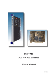
1
SIS Documentation SIS1100/3100 PCI to VME SIS1100/3100 Standard design Firmware Version 5/6 User Manual SIS GmbH Harksheider Str. 102A 22399 Hamburg Germany Phone: ++49 (0) 40 60 87 305 0 Fax: ++49 (0) 40 60 87 305 20 email: [email protected] http://www.struck.de Version: 1.33 as of 24.02.04 Page 1 of 80 SIS Documentation SIS1100/3100 PCI to VME Revision Table: Revision 0.0 0.1 1.0 1.1 Date 19.01.01 13.07.01 26.10.01 05.11.01 1.11 26.11.01 1.20 1.21 1.30 29.01.01 04.06.02 17.08.02 1.31 1.32 1.33 23.04.03 16.12.03 24.02.04 Page 2 of 80 Modification Generation mki touch up Initial release - OPT-IN/OUT register - OPT-IN register - OPT-VME-Interrupt register - Doorbell register - VME SLAVE register description SIS9200 SHARC option registers added Modifications for firmware V_310502 Firmware version 5 VME interrupt generation added Multi master section added 3U cPCI front panel added bug fix in texts of IRQ generation register add auto copy address range to SHARC address map SIS Documentation SIS1100/3100 PCI to VME 1 Table of contents 1 2 3 4 5 6 7 Table of contents .............................................................................................................................................3 Introduction .....................................................................................................................................................5 Overview .........................................................................................................................................................6 3.1 Design Concept of VME side ..................................................................................................................7 3.1.1 I/O Option........................................................................................................................................8 3.1.2 DSP option.......................................................................................................................................8 3.1.3 SDRAM option................................................................................................................................8 3.2 Design concept of PCI side (SIS1100) ....................................................................................................9 3.2.1 I/O Option........................................................................................................................................9 Gigabit Hardware ..........................................................................................................................................10 Gigabit-Link Transfer Protocol .....................................................................................................................10 5.1 Protocol Integrity ..................................................................................................................................10 5.2 General Transfer Protocol......................................................................................................................11 5.3 Protocol Header, special word ...............................................................................................................12 5.4 VME Access ..........................................................................................................................................14 5.4.1 VME D08 and BLT8 Access .........................................................................................................14 5.4.2 VME D16 and BLT16 Access .......................................................................................................14 5.4.3 VME D32 and BLT32 Access .......................................................................................................15 5.4.4 VME BLT64 Access......................................................................................................................15 5.5 Remote Register Transfer Protocol........................................................................................................17 5.5.1 Write remote register .....................................................................................................................17 5.5.2 Read remote register ......................................................................................................................17 5.6 Direct VME Bus Access Transfer Protocol ...........................................................................................18 5.6.1 Single Word Write Direct VME Bus Access.................................................................................18 5.6.2 Single Word Read Direct VME Bus Access..................................................................................19 5.6.3 Block transfer Write Direct VME Bus Access ..............................................................................20 5.6.4 Block transfer Read Direct VME Bus Access ...............................................................................20 5.7 Mapped VME Bus Access Transfer Protocol ........................................................................................21 5.7.1 Single Word Write mapped VME Bus Access ..............................................................................21 5.7.2 Single Word Read mapped VME Bus Access ...............................................................................21 5.7.3 Block transfer Write mapped VME Bus Access............................................................................22 5.7.4 Blocktransfer Read mapped VME Bus Access..............................................................................22 5.8 SDRAM Transfer Protocol ...................................................................................................................23 5.8.1 Single Word Write SDRAM..........................................................................................................23 5.8.2 Single Word Read SDRAM...........................................................................................................23 5.8.3 Blocktransfer Write SDRAM ........................................................................................................24 5.8.4 Blocktransfer Read SDRAM .........................................................................................................24 SIS3100 Access through the Optical Interface ..............................................................................................25 6.1 Control register space ............................................................................................................................25 6.1.1 Type-Identifier/Version register(0x0, read)...................................................................................26 6.1.2 Optical status register (0x4, r/w)....................................................................................................27 6.1.3 Optical control register (0x8, r/w) .................................................................................................28 6.1.4 OPT-IN/OUT Register (0x80,read /write) .....................................................................................29 6.1.5 OPT-IN-LATCH_IRQ Register (0x84,read /write).......................................................................30 6.1.6 OPT-VME-Master Status/Control register (0x100,read/write)......................................................31 6.1.7 OPT-VME Interrupt Status/Control register (0x104,read /write) .................................................33 6.1.8 VME interrupt register (0x110, r/w)..............................................................................................36 6.1.9 OPT-VME-Slave Status/Control register (0x200,read /write)......................................................37 6.1.10 OPT-VME-Master DMA_WRITE_BYTE_counter register (0x204,read)...................................38 6.1.11 OPT-DSP Status/Control Register (0x300, r/w) ............................................................................39 6.1.12 OPT-VME-Address MAP register 0..255 (0x400..0x7FC,read/write) ..........................................40 6.2 OPT-Sharc space ...................................................................................................................................41 6.3 OPT-SDRAM space .............................................................................................................................42 6.3.1 OPT_SDRAM_SPD register .........................................................................................................43 VME slave access..........................................................................................................................................44 7.1 VME Slave Address Map ......................................................................................................................44 7.2 Type-Identifier/Version register(0x0, read)...........................................................................................45 Page 3 of 80 SIS Documentation SIS1100/3100 PCI to VME 7.3 VS-DSP Status/Control Register (0x10, r/w) ........................................................................................46 7.4 SDRAM Page Register (0x14, r/w) .......................................................................................................47 8 VME side LEDs.............................................................................................................................................48 8.1 Front panel LEDs...................................................................................................................................48 8.1.1 Explanation of front panel LEDs ...................................................................................................49 8.1.2 Special case: LED Link up off.......................................................................................................49 8.2 PCB LEDs .............................................................................................................................................49 9 SIS3100 Jumpers ...........................................................................................................................................50 9.1 J10 .........................................................................................................................................................50 9.2 J90 .........................................................................................................................................................51 9.2.1 JP_DSP ..........................................................................................................................................51 10 VME master/system controller ..................................................................................................................52 10.1 Multi master operation...........................................................................................................................52 10.1.1 System Controller ..........................................................................................................................52 10.1.2 Bus grant/bus mastership ...............................................................................................................52 11 SHARC resources......................................................................................................................................53 11.1 SHARC address map .............................................................................................................................53 11.1.1 SHARC Local Bus interface registers ...........................................................................................54 11.1.2 Address map of SHARC registers .................................................................................................58 11.1.3 Address map of SHARC-Optical Dual Ported Ram ......................................................................58 11.2 SHARC flags .........................................................................................................................................66 11.3 SHARC DSP interrupts .........................................................................................................................67 11.3.1 DSP Interrupt sources ....................................................................................................................67 11.3.2 DSP Interrupt configuration...........................................................................................................67 12 SIS1100 Hardware Description .................................................................................................................68 12.1 PCI Front panel......................................................................................................................................68 12.2 3U cPCI front panel ...............................................................................................................................69 12.3 SIS1100 LEDs .......................................................................................................................................69 12.3.1 Front panel LEDs...........................................................................................................................69 12.3.2 SIS1100-OPT PCB LEDs..............................................................................................................70 12.3.3 SIS1100-CMC PCB LEDs.............................................................................................................70 12.4 SIS1100 Input termination.....................................................................................................................71 13 Appendix ...................................................................................................................................................72 13.1 Power consumption ...............................................................................................................................72 13.2 I/O option Jumper description ...............................................................................................................73 13.2.1 JP710 .............................................................................................................................................73 13.2.2 JP770 .............................................................................................................................................73 13.2.3 Schematic of flat I/O connector .....................................................................................................74 13.2.4 Schematic of LEMO I/O section....................................................................................................75 13.3 Boot mechanisms...................................................................................................................................76 13.3.1 ISP PROM .....................................................................................................................................76 13.3.2 JTAG .............................................................................................................................................76 13.4 Connector types .....................................................................................................................................77 14 Index ..........................................................................................................................................................78 Page 4 of 80 SIS Documentation SIS1100/3100 PCI to VME 2 Introduction The goal of the project was the development of a high performance VME list sequencer to PCI interface, which was tailored to match the requirements of Particle Physics experiments, related applications and other demanding data acquisition systems. The maximum anticipated data rate on the VME side, required medium to long link distances in large scale setups and the wish for electrical decoupling resulted in the selection of a fibre optic Gigabit solution as the interconnecting technology. As we are aware, that no manual is perfect, we appreciate your feedback and will try to incorporate proposed changes and corrections as quickly as possible. The most recent version of this manual can be obtained by email from [email protected], the revision dates are online under http://www.struck.de/manuals.htm. A list of available firmware designs can be retrieved from http://www.struck.de/sis3100firm.htm Note: The SIS1100/3100 PCI to VME interface was developed in a collaborative effort between the ZEL department of the Research Center Jülich and SIS GmbH. Page 5 of 80 SIS Documentation SIS1100/3100 PCI to VME 3 Overview The SIS PCI to VME interface consists of the SIS1100 PCI card and the SIS3100 VME list sequencer and an interconnecting link fibre. The SIS1100 card is divided into the SIS1100CMC PCI CMC (common mezzanine card) and the SIS1100-OPT gigabit link CMC card. VME Fiber PCI SIS1100-CMC SIS1100-OPT Page 6 of 80 SIS3100 SIS Documentation SIS1100/3100 PCI to VME 3.1 Design Concept of VME side The VME side of the PCI to VME interface, the SIS3100, is a modular design, that can be configured for the given application. Find below a list of key features of the SIS3100. • • • • • • • • • • • • • VME List sequencer Mapping table with 256 entries VME Master: A16/A24/A32/A40 D8/D16/D32/BLT32/MBLT64/2eMBLT64 VME Slave: A32/D32/BLT32/MBLT64 Block transfer address auto increment on/off (for FIFO reads) System controller function (can be disabled by jumper) Hot swap (in conjunction with VME64x backplane) VME64x Connectors VME64x Side Shielding VME64x Front panel VME64x extractor handles (on request) 10 front panel and 8 PCB LEDs single supply (+5 V) A block diagram of the SIS3100 is shown below. Serialiser/ Deserialiser SHARC DSP Option Front Panel I/O Option I/O FPGA Protocol FPGA FIFO FIFO VME FPGA VME Link Medium SDRAM Option Options SIS3100 block diagram Page 7 of 80 SIS Documentation SIS1100/3100 PCI to VME 3.1.1 I/O Option The I/O option features extended data handling and input/output functionality. It comprises the I/O FPGA, connectors for the optional SIS9200 SHARC DSP , the DIMM socket and the front panel input/output hardware, which features: • 4 flat cable inputs (ECL or TTL) • 4 flat cable output (ECL or TTL) • 3 LEMO inputs (NIM or TTL) • 3 LEMO outputs (NIM or TTL) • 1 LEMO reset input (NIM or TTL ) • 1 LEMO reset input (NIM or TTL ) The inputs can be used for conditional VME sequencer control and the outputs can be set/cleared under sequencer control for interaction with external dead time or other logic. This results in a substantial increase in performance compared to the use of an external VME I/O register, as no VME cycle (leave alone interrupt cycle) is involved. 3.1.2 DSP option The DSP option comprises a SIS9200 SHARC DSP piggy back board with SHARC links (i.e. ADSP21062L chip) for histogramming or higher level trigger applications. 3.1.3 SDRAM option The SDRAM option consists of the DRAM controller firmware and a SDRAM memory strip, which is available in 64, 128, 256 and 512 MByte Page 8 of 80 SIS Documentation SIS1100/3100 PCI to VME 3.2 Design concept of PCI side (SIS1100) The SIS1100 PCI Gigabit link card was developed to act as PCI target and initiator to allow for the use of PCI block transfer cycles. A PLX9054 PCI to local bus interface, which is PCI 2.1 and 2.2 compliant is used as the interfacing hardware. The SIS1100 is subdivided into the SIS1100-CMC, which is a CMC carrier board, and the SIS1100-OPT, which is a CMC Gigabit link board.. • • • • • • • • PCI 2.1 and 2.2 compliant PLX9054 PCI master bridge chip Protocol FPGA serial configuration PROMs for FPGA and PLX bridge JTAG port to FPGA PROM and FPGA CMC (IEEE P1386 Draft 2.3) single size carrier all CMC data lines routed to FPGA 4 SMD LEDs routed to FPGA CMC JTAG serial PROM FPGA EEPROM Bridge PCB LEDs PCI Bus Block diagram of SIS1100-CMC 3.2.1 I/O Option The I/O option for the SIS1100-CMC, which can be used on the SIS1100 board was introduced to allow for direct interaction with the readout PC. The input/output option features: • • 2 LEMO inputs (TTL) 2 LEMO outputs (TTL) Page 9 of 80 SIS Documentation SIS1100/3100 PCI to VME 4 Gigabit Hardware Small form factor (SFF) Gigabit link media were chosen as the physical layer of the link of the SIS PCI to VME interface. Media with LC connectors are used, patch fibres to other standards like ST are readily available for large scale connections through 19” patch fields. The link is clocked at 125 MHz (i.e. a 62.5 MHz clock is doubled by a delay locked loop in the protocol XILINX FPGA ), what results in a payload of 125 Mbytes/s. With the standard multimode link media distances of up to 450 m can be covered, single mode media and fibres extend the range up to 80 km. Due to pipelining single cycle and high speed block transfer capabilities link latency will not play a significant role for most applications even at very long distances. 5 Gigabit-Link Transfer Protocol 32-bit words are transmitted over the Gigabit-Link. The link hardware is in charge of proper structure. Loss of synchronisation or errors are reported to the corresponding host. Any transmission starts with a special word, in the case of a block transfer it can end with a special character also if the transfer length is undefined or smaller than the requested length. One bit in the FIFOs is used to flag a special word, with Byte 0 being 0x1C (SC_PROT K28.0). Byte loss can be detected as all 4 Bytes of a word are transmitted without interruption. All characters up to the next special character are ignored if the data link layer detects an error. 5.1 Protocol Integrity A protocol sequence has to be transmitted without interruption, i.e. a mixture of request and confirmation protocols is not allowed. Page 10 of 80 SIS Documentation 5.2 SIS1100/3100 PCI to VME General Transfer Protocol The protocol structure depends on the protocol header (special word). In general the transfer protocol structure is as described in the table below. special word Bit[31:24] phys. Byte 0 Bit[23:16] Byte 1 Bit[15:8] Byte 2 Bit[7:0] Byte 3 SC_PROT Special Char ctl: control sp: space be: byte enable AM Address Modifier Bit 15:0 direct VME access only ADDR_H Address A63-32 64 Bit only ADDR_L Address A31-0 DATA_H Data D63-32 (register contents swapped) DATA_L/BC Data D31-0/Byte count with BT Read DATA consecutive data word(s) Blockt ransfer ... special word 64 Bit only Write only SC_PROT ctl: END The individual 32-bit words are transmitted beginning with Byte 0, a protocol sequence starts with special character SC_PROT always. Hence this Byte is transmitted as the first Byte of the special words. As mentioned above the value is 0x1C (SC_PROT, K28.0). Page 11 of 80 SIS Documentation 5.3 SIS1100/3100 PCI to VME Protocol Header, special word The special word is formed as illustrated in the table below Bit Byte 31-24 FF000000 Bit Comment SC_PROT 0x1C always 23 CTL (Control) EOT DMA end To be set in protocol END only 22 FIFO no address increment With BT (block transfer) only BT block transfer The address is followed by the byte count (1 word) in a read request. A64 64/bit address with request protocol only AM address modifier contained An AM can be present in a request protocol only WR write request 0: 1: 00 01 10 11 REQ END CON ECON Request, protocol start End of block transfer Confirmation, positive confirmation Error confirmation 0: 1: 2: 3: normal transfer Buffer pipe DMA0 pipe reserved Local space, to be used for pipelined read 0: 1: 2-4: 6: register remote space: 00800000 00400000 21 00200000 20 00100000 19 00080000 18 00040000 17-16 00030000 15-14 SP Space, to be returned unchanged 0000C000 13-8 00003F00 direct VME access not used SDRAM, DSP read write Not used with SIS3100 interpreted by SIS3100 7-13: not used 7-0 BE (request) EC (confirm) 000000FF 01 02 04 08 F0 Byte 0 Byte 1 Byte 2 Byte 3 Byte 7-4 Byte enable is ignored during a register transfer, as a 32-bit word is transmitted the value should be 0x0F however. Two data words (64-bit) are expected if enable of Byte 7-4 is different from 0 This byte holds the error information on error confirmation (ECON) Page 12 of 80 SIS Documentation SIS1100/3100 PCI to VME Byte Enable Bits Summary Byte Enable Combination 00 invalid 01 valid byte 02 valid byte 03 valid double byte 04 valid byte 05 invalid 06 invalid 07 invalid 08 valid 09 invalid 0A invalid 0B invalid 0C valid 0D invalid 0E invalid 0F valid quad byte 10 valid eight byte transfer .. valid eight byte transfer FF valid eight byte transfer NOTE: Transfer length byte double byte The VME access width (D8/D16/D32/D64) is defined by the Byte enable bits Page 13 of 80 SIS Documentation 5.4 SIS1100/3100 PCI to VME VME Access 5.4.1 VME D08 and BLT8 Access During VME single byte transfers (D08 und BLT8) one valid Byte only is transferred over the optical link per 32-bit word. Assignment of Byte Enable Bits VME DS1* VME DS0* VME A1 VME A2 VME Lword * [15:8] low high 0 (a1) a2 high [23:16] [7:0] high low 0 (a1) a2 high [23:16] [15:8] [15:8] low high 1 (a1) a2 high [31:24] [7:0] [7:0] high low 1 (a1) a2 high Adress End Bits Byte Enable PCI data bits Little Endian Optical data bits Big Endian VME data bus (a1 a0) BE valid bits valid bits valid bits ..00 01 [7:0] [31:24] ..01 02 [15:8] ..10 04 ..11 08 * low active During a block transfer (BT) 8-bit per 32-bit word are transferred also, the start address a1, a0 defines which data bits are valid during the first data word. During consecutive Bytes the data bits will become valid in following order: : .... [31:24], [23:16], [15:8], [7:0] , [31:24], ..... 5.4.2 VME D16 and BLT16 Access During a VME double byte transfer (D16 and BLT16) two valid Bytes are transferred over the optical link per 32-bit word. Assignment Byte Enable Bits Address End Bits Byte Enable Little Endian Big Endian (Optical data bits) VME data bus VME VME DS1* DS1* ..00 03 [7:0], [15:8] [31:24], [23:16] [15:0] low ..10 0C [23:16], [31:24] [15:8], [7:0] [15:0] low VME A1 VME A2 VME Lword* low 0 (a1) a2 high low 1 (a1) a2 high (a1 a0) Rule: a0 must be 0 if Byte Enable = 03 or 0C The start address a1 defines which data bits of the first data word are valid. During consecutive double Bytes the data bits will become valid in following order: [31:16], [15:0], [31:16], [15:0], ..... Page 14 of 80 SIS Documentation SIS1100/3100 PCI to VME 5.4.3 VME D32 and BLT32 Access All 32-bits on the optical data path are valid during a VME quad byte transfer (D32 and BLT32). Assignment of Byte Enable Bits Address End Bits Byte Enable Little Endian Big Endian (Optical data bits) VME data bus VME VME VME DS1* DS1* A1 VME A2 VME Lword* 0F [7:0], [15:8], [31:24], [23:16], D[31:0] low a2 low [23:16], [31:24] [15:8], [7:0] (a1 a0) ..00 low 0 (a1) Rule: a1, a0 must be 00 if Byte Enable = 0x0F 5.4.4 VME BLT64 Access Two 32-bit data words are transmitted over the optical link during a multiplexed VME eight byte block transfer (MBLT64). Assignment of Byte Enable Bits Address End Bits Byte Enable Little Endian Big Endian (Optical data bits) VME data bus VME VME DS1* DS1* low (a2, a1 a0) 1. datum ..000 10..ff [7:0], [15:8], [63:56], [55:48], A[31:1], [23:16], [31:24] [47:40], [39:32] LOWRD* low 2. datum [39:32], [47:40], [31:24], [23:16], [55:48], [63:56] [15:8], [7:0] D[31:0] Rule: a2, a1, a0 must be 000 if Byte Enable = BLT64 Page 15 of 80 SIS Documentation SIS1100/3100 PCI to VME AM Protocol word Function of AM Protocol Bits on VME Cycle AM Protocol 15 VME 14 IRQ ACK Cycle * low active Page 16 of 80 11 10 9 8 7 [7:6] [5:0] AM [5:0] SIS Documentation 5.5 SIS1100/3100 PCI to VME Remote Register Transfer Protocol SC_PROT: CTL: 0x1C xxx SP: BE: (immer) 0x00: 0x0F: EOT: FIFO: BT: A64: AM: WR: 0 (not used here) 0 (not used here) 0 (not used here) 0 (not used here) 0 (not used here) 0 -> Read; REQ: CON: ECON: 00 10 11 1 -> Write (Bit17,16) (Bit17,16; postive Confirmation) (Bit17,16; negative Confirmation) Register 32-bit transfer (register access 32-bit always) 5.5.1 Write remote register CTL: 0x04 (REQ and WR) Request (from PCI) Confirmation from SIS3100 Bit 31 SC_PROT Bit 0 CTL : 0x04 SP: 00 Bit 31 Bit 0 BE: 0F Address A31-0 data SC_PROT CTL: 0x6 SP: 00 --- CTL: 0x7 SP: 00 EC or in case of error SC_PROT 5.5.2 Read remote register CTL: 0x00 (REQ and RD) Request (from PCI) Bit 31 SC_PROT Confirmation from SIS3100 Bit 0 CTL : 0x00 SP: 00 Bit 31 Bit 0 BE: 0F Address A31-0 SC_PROT CTL: 0x2 SP: 00 --- SP: 00 EC data or in case of error SC_PROT CTL: 0x3 EC to be defined Page 17 of 80 SIS Documentation 5.6 SIS1100/3100 PCI to VME Direct VME Bus Access Transfer Protocol SC_PROT: CTL: 0x1C xxx (always) EOT: FIFO: BT: A64: WR: 0 -> no address increment; 1 -> address increment (relevant with BT only) 0 -> single cycle; 1 -> block transfer 0 -> addresse A31-0 only part of request protokol 1 -> address A63-32 and address A31-0 part of request protocol 0 -> AM Code not part of request protocol ( default:AM=0x09 ;A32 non priv. data) 1 -> AM Code part of request protocol 0 -> Read; 1 -> Write REQ: CON: ECON: 00 10 11 AM: SP: BE: 0x01: xx (Bit17,16) (Bit17,16; positive confirmation) (Bit17,16; negative confirmation) direct VME bus access 5.6.1 Single Word Write Direct VME Bus Access CTL: CTL: CTL: 0x04 0x0C 0x1C (REQ and WR) (REQ and WR and AM) (REQ and WR and AM and A64) Request (from PCI) Confirmation from SIS3100 Bit 31 Bit 0 SC_PROT CTL SP: 01 Bit 31 Bit 0 BE: 0F address modifier (with CTL:AM =1 only) Address A63-32 (with CTL:A64 =1 only) address A31-0 data SC_PROT CTL: 0x6 ? SP: 01 --- CTL: 0x7 ? SP: 01 EC or in error case SC_PROT Page 18 of 80 SIS Documentation 5.6.2 SIS1100/3100 PCI to VME Single Word Read Direct VME Bus Access CTL: CTL: CTL: 0x00 0x08 0x18 (REQ and RD) (REQ and RD and AM) (REQ and RD and AM and A64) Request (from PCI) Confirmation from SIS3100 Bit 31 Bit 0 SC_PROT CTL SP: 01 Bit 31 Bit 0 BE: 0F address modifier (with CTL:AM =1 only) address A63-32 (with CTL:A64 =1 only) address A31-0 SC_PROT CTL: 0x2 ? SP: 01 --- SP: 01 EC data or in error case SC_PROT CTL: 0x3 ? Page 19 of 80 SIS Documentation SIS1100/3100 PCI to VME 5.6.3 Block transfer Write Direct VME Bus Access CTL: CTL: 0x24 0x81 (REQ , WR and BT) (END and EOT; arbitrary: WR and BT) Request (from PCI) Confirmation from SIS3100 Bit 31 Bit 0 SC_PROT CTL SP: 01 Bit 31 Bit 0 BE: 0F address nodifier (with CTL:AM =1 only) address A63-32 (with CTL:A64 =1 only) (Start) address A31-0 (4 Byte aligned) datum 1 datum 2 ....... datum n SC_PROT CTL : 0x81 SP: 01 BE: 0F SC_PROT CTL: 0x26 ? SP: 01 --- CTL: 0x27 ? SP: 01 EC or in error case SC_PROT 5.6.4 Block transfer Read Direct VME Bus Access CTL: CTL: CTL: 0x20 0x22 0x81 (REQ and BT) (CONF and BT; arbitrary: WR and BT) (END and EOT; arbitrary: WR and BT) Request (from PCI) Confirmation from SIS3100 Bit 31 Bit 0 SC_PROT CTL : 0x20 SP: 01 Bit 31 Bit 0 BE: 0F address modifier (with CTL:AM =1 only) address A63-32 (with CTL:A64 =1 only) (Start) address A31-0 (4 Byte aligned) BC (byte count; 4-er steps: 4,8, ...) SC_PROT CTL: 0x22 SP: 01 --- CTL: 0x81 ? SP: 01 --- CTL: 0x23 ? SP: 01 EC datum 1 datum 2 .. datum n SC_PROT or in error case SC_PROT Page 20 of 80 SIS Documentation 5.7 SIS1100/3100 PCI to VME Mapped VME Bus Access Transfer Protocol SC_PROT: CTL: SP: BE: 0x1C xxx 0x04: xx (immer) EOT: FIFO: BT: A64: AM: WR: 0 -> no address increment; 1 -> address increment (relevant with BT only ) 0 -> single cycle access; 1 -> block transfer 0 (not relevant here) 0 (not relevant here) 0 -> Read; 1 -> Write REQ: CON: ECON: 00 10 11 (Bit17,16) (Bit17,16; positive confirmation) (Bit17,16; negative confirmation) mapped VME bus access 5.7.1 Single Word Write mapped VME Bus Access CTL: 0x04 (REQ and WR) Request (from PCI) Confirmation from SIS3100 Bit 31 Bit 0 SC_PROT CTL SP: 04 Bit 31 Bit 0 BE: 0F address A31-0 A31-24: not used A23-16: address (and AM) map pointer A15-0: direct to VME datum SC_PROT CTL: 0x6 ? SP: 04 --- CTL: 0x7 ? SP: 04 EC or in error case SC_PROT 5.7.2 Single Word Read mapped VME Bus Access CTL: 0x00 (REQ and RD) Request (from PCI) Confirmation from SIS3100 Bit 31 Bit 0 SC_PROT CTL SP: 04 Bit 31 Bit 0 BE: 0F address A31-0 A31-24: not used A23-16: address (and AM) map pointer A15-0: direct to VME SC_PROT CTL: 0x2 ? SP: 04 --- SP: 04 EC datum or in error case SC_PROT CTL: 0x3 ? Page 21 of 80 SIS Documentation SIS1100/3100 PCI to VME 5.7.3 Block transfer Write mapped VME Bus Access CTL: CTL: 0x24 0x81 (REQ , WR and BT) (END and EOT; arbitrary: WR and BT) Request (from PCI) Confirmation from SIS3100 Bit 31 Bit 0 SC_PROT CTL SP: 01 Bit 31 Bit 0 BE: 0F address A31-0 A31-24: not used A23-16: address (and AM) map pointer A15-0: direct to VME datum 1 datum 2 ....... datum n SC_PROT CTL : 0x81 SP: 04 BE: 0F SC_PROT CTL: 0x26 ? SP: 04 --- CTL: 0x27 ? SP: 04 EC or in error case SC_PROT 5.7.4 Blocktransfer Read mapped VME Bus Access CTL: CTL: CTL: 0x20 0x22 0x81 (REQ and BT) (CONF and BT; arbitrary: WR and BT) (END and EOT; arbitrary: WR and BT) Request (from PCI) Confirmation from SIS3100 Bit 31 Bit 0 SC_PROT CTL : 0x20 SP: 04 Bit 31 Bit 0 BE: 0F address A31-0 A31-24: not used A23-16: address (and AM) map pointer A15-0: direct to VME BC (byte count; in steps of 4: 4,8, ...) SC_PROT CTL: 0x22 SP: 04 --- CTL: 0x81 ? SP: 04 --- CTL: 0x23 ? SP: 04 EC datum 1 datum 2 .. datum n SC_PROT or in error case SC_PROT Page 22 of 80 SIS Documentation 5.8 SIS1100/3100 PCI to VME SDRAM Transfer Protocol SC_PROT: CTL: SP: BE: 0x1C xxx 0x06: 0x0F: (always) EOT: FIFO: BT: A64: AM: WR: 0 (not relevant) 0 -> Einzelwortzugriff; 1 -> Block transfer 0 (not relevant) 0 (not relevant) 0 -> Read; 1 -> Write REQ: CON: CON: 00 10 11 (Bit17,16) (Bit17,16; positive confirmation) (Bit17,16; negative confirmation) SDRAM 32-bit transfer (not used, register access is 32-bit wide by default) 5.8.1 Single Word Write SDRAM CTL: 0x04 (REQ and WR) Request (from PCI) Confirmation from SIS3100 Bit 31 SC_PROT Bit 0 CTL : 0x04 SP: 06 Bit 31 Bit 0 BE: 0F address A31-0 datum SC_PROT CTL: 0x6 SP: 06 --- CTL: 0x7 SP: 06 EC or in error case SC_PROT 5.8.2 Single Word Read SDRAM CTL: 0x00 (REQ and RD) Request (from PCI) Bit 31 SC_PROT Confirmation from SIS3100 Bit 0 CTL : 0x00 SP: 06 Bit 31 Bit 0 BE: 0F address A31-0 SC_PROT CTL: 0x2 SP: 06 --- SP: 06 EC datum or in error case SC_PROT CTL: 0x3 Page 23 of 80 SIS Documentation SIS1100/3100 PCI to VME 5.8.3 Blocktransfer Write SDRAM CTL: CTL: 0x24 0x81 (REQ , WR and BT) (END and EOT; arbitrary: WR and BT) Request (from PCI) Confirmation from SIS3100 Bit 31 Bit 0 SC_PROT CTL : 0x24 SP: 06 Bit 31 Bit 0 BE: 0F (Start) address A31-0 (4 Byte aligned) datum 1 datum 2 ....... datum n SC_PROT CTL : 0x81 SP: 06 BE: 0F SC_PROT CTL: 0x26 SP: 06 --- CTL: 0x27 SP: 06 EC or in error case SC_PROT 5.8.4 Blocktransfer Read SDRAM CTL: CTL: CTL: 0x20 0x22 0x81 (REQ and BT) (CONF and BT; arbitrary: WR and BT) (END and EOT; arbitrary: WR and BT) Request (from PCI) Confirmation from SIS3100 Bit 31 Bit 0 SC_PROT CTL : 0x20 SP: 06 Bit 31 Bit 0 BE: 0F (Start) Address A31-0 (4 Byte aligned) BC (byte count; 4-er steps: 4,8, ...) SC_PROT CTL: 0x22 SP: 06 --- CTL: 0x81 SP: 06 --- CTL: 0x23 SP: 06 EC data 1 data 2 .. data n BC (n x 4) SC_PROT or in error case SC_PROT Page 24 of 80 SIS Documentation SIS1100/3100 PCI to VME 6 SIS3100 Access through the Optical Interface 6.1 Control register space Offset Access Function 0x000 0x004 0x008 R R/W R/W Type-Identifier/Version register Optical Status register Optical Control register (reserved functions) 0x080 0x084 R/W R/W OPT-IN/OUT Register (FLAT/LEMO I/O) OPT-IN-LATCH_IRQ Register 0x100 0x104 0x110 R/W R/W R/W OPT-VME-Master Status/Control register OPT-VME-Master Interrupt Status/Control register 0x200 0x204 R/W R OPT-VME-Slave Status/Control register OPT-VME-Master DMA_WRITE_BYTE_COUNTER 0x300 R/W OPT-DSP Status/Control Register OPT-VME Interrupt generation register (added with firmware version 5) Control register space can be accessed with the routines: int s3100_control_read(int p, int offset, u_int32_t* data) int s3100_control_write(int p, int offset, u_int32_t data) Note: long word access, the offset has to be long word aligned (0x0, 0x4, 0x8 ...) Page 25 of 80 SIS Documentation SIS1100/3100 PCI to VME 6.1.1 Type-Identifier/Version register(0x0, read) This read only register holds the SIS3100 board type to allow for a distinction between different interface types. The board type of the SIS3100 VME side is 2. Find below a table of board types (for the time being PCI and VME are the only implemented boards). BIT access Name 31-24 RO Function Firmware Version 1..255 Firmware Id. 1 = universal FF000000 23-16 RO 00FF0000 other Ids. for dedicated firmware 15-8 RO Hardware Version 1..255 Identifier 1 = PCI/PLX Interface (SIS1100) 2 = VME Controller (SIS3100) 3 = CAMAC/FERA Controller (SIS5100) 4 = Readout system with LVD SCSI 0000FF00 7-0 RO 000000FF 0x02 Example: The current version reads 0x 05 01 01 02 Page 26 of 80 SIS Documentation SIS1100/3100 PCI to VME 6.1.2 Optical status register (0x4, r/w) BIT Name access Function RO 0x0000 BAND_ERROR WR: sel clr VSC: Out-of-Band Error (not reseted after powerup and Link reset) DISPAR_ERROR WR: sel clr VSC: Disparity Error (not reseted after powerup and Link reset) UORUN_ERROR WR: sel clr VSC: Under/Overrun error (not reseted after powerup and Link reset) TBERR_ERROR WR: sel clr VSC: Transmit Buffer Error(not reseted after powerup and Link reset) 31-16 reserved FFFF0000 15 00008000 14 00004000 13 00002000 12 00001000 11 0 00000800 10 LWORD_ERROR WR: sel clr Lword aligned error on optical interface 00000400 9 0 00000200 8 0 00000100 7 REC_VIOLATION 0 (reserved) SEMA_CHG 0 (reserved) 00000080 6 00000040 5 INH_CHG WR: sel clr INHIBIT signal has changed (to inhibit) SYNCH_CHG WR: sel clr RX/TX_SYNCH has changed CONFIGURED RO allows remote side to detect RESET or power up 00000020 4 00000010 3 00000008 (1 after reset or power up) 2 INHIBIT RO Transfer to remote side locked (TRANS_WAIT_FLAG_L) 00000004 remote has send xoff or TRANSMIT_LINK_WAIT is active 1 TX_SYNCH RO Optical remote receiver is synchronised 00000002 (TRANSMIT_LINK_OK) 0 RX_SYNCH RO Optical receiver is synchronised (RECEIVE_LINK_OK) 00000001 Page 27 of 80 SIS Documentation SIS1100/3100 PCI to VME 6.1.3 Optical control register (0x8, r/w) This register is implemented as a selective J/K register. The user has to avoid to write a 1 to the clear and set bit of the same output at the same time, as an undefined toggle state may result. The functions are reserved. They will be used in applications like VME to VME coupling. Bit 31:16 15:0 Write Function Clear reserved bit [15:0] Set reserved bit [15:0] Page 28 of 80 Read Function 0x0000 Status reserved bit [15:0] SIS Documentation SIS1100/3100 PCI to VME 6.1.4 OPT-IN/OUT Register (0x80,read /write) This register is under control of the Input/Output option (as far as installed on the given SIS3100). On read access the status of the outputs and the current level on the inputs can be obtained, on write access the level of the outputs can be set. The register is implemented as a selective J/K register, the specific function (set/clear output) is executed by writing a 1 to the corresponding bit location, writes with a 0 have no effect. The user has to avoid to write a 1 to the clear and set bit of the same output at the same time, as an undefined toggle state may result. Bit 31 30 29 28 27 26 25 24 23 22 21 20 19 18 17 16 15 14 13 12 11 10 9 8 7 6 5 4 3 2 1 0 Write Function no function Generate pulse LEMO_OUT3 Generate pulse LEMO_OUT2 Generate pulse LEMO_OUT1 Generate pulse FLAT_OUT4 Generate pulse FLAT_OUT3 Generate pulse FLAT_OUT2 Generate pulse FLAT_OUT1 no function Clear LEMO_OUT3 Clear LEMO_OUT2 Clear LEMO_OUT1 Clear FLAT_OUT4 Clear FLAT_OUT3 Clear FLAT_OUT2 Clear FLAT_OUT1 no function no function no function no function no function no function no function no function no function Set LEMO_OUT3 Set LEMO_OUT2 Set LEMO_OUT1 Set FLAT_OUT4 Set FLAT_OUT3 Set FLAT_OUT2 Set FLAT_OUT1 Read Function 0 0 0 0 0 0 0 0 0 Status LEMO_IN3 Status LEMO_ IN2 Status LEMO_ IN1 Status FLAT_ IN4 Status FLAT_ IN3 Status FLAT_ IN2 Status FLAT_ IN1 0 0 0 0 0 0 0 0 0 Status LEMO_OUT3 Status LEMO_OUT2 Status LEMO_OUT1 Status FLAT_OUT4 Status FLAT_OUT3 Status FLAT_OUT2 Status FLAT_OUT1 pulse length : 12.5ns pulse polarity: if SET_OUTx is set then the polarity is inverted Page 29 of 80 SIS Documentation SIS1100/3100 PCI to VME 6.1.5 OPT-IN-LATCH_IRQ Register (0x84,read /write) This register is under control of the Input/Output option (as far as installed on the given SIS3100). On read access the status of the outputs and the current level on the inputs can be obtained, on write access the level of the outputs can be set. The register is implemented as a selective J/K register, the specific function (set/clear output) is executed by writing a 1 to the corresponding bit location, writes with a 0 have no effect. The user has to avoid to write a 1 to the clear and set bit of the same output at the same time, as an undefined toggle state may result. Bit 31 30 29 28 27 26 25 24 23 22 21 20 19 18 17 16 Write Function Clear DSP_IRQ_LATCH bit Clear LEMO_IN3_LATCH bit Clear LEMO_IN2_LATCH bit Clear LEMO_IN1_LATCH bit Clear FLAT_ IN4_LATCH bit Clear FLAT_ IN3_LATCH bit Clear FLAT_ IN2_LATCH bit Clear FLAT_ IN1_LATCH bit Clear DSP_IRQ_Enable bit Clear LEMO_IN3_IRQ Enable bit Clear LEMO_IN2_IRQ Enable bit Clear LEMO_IN1_IRQ Enable bit Clear FLAT_ IN4_IRQ Enable bit Clear FLAT_ IN3_IRQ Enable bit Clear FLAT_ IN2_IRQ Enable bit Clear FLAT_ IN1_IRQ Enable bit Read Function Status DSP_IRQ_LATCH bit Status LEMO_ IN3_LATCH bit Status LEMO_ IN2_LATCH bit Status LEMO_ IN1_LATCH bit Status FLAT_ IN4_LATCH bit Status FLAT_ IN3_LATCH bit Status FLAT_ IN2_LATCH bit Status FLAT_ IN1_LATCH bit Status DSP_IRQ_Enable Status LEMO_IN3 Status LEMO_IN2 Status LEMO_IN1 Status FLAT_IN4 Status FLAT_IN3 Status FLAT_IN2 Status FLAT_IN1 15 1 Shot: IRQ_UPDATE Status DSP_IRQ bit 14 13 12 11 10 9 8 7 6 5 4 3 2 1 0 no function no function no function no function no function no function no function SET DSP_IRQ Enable bit Set LEMO_IN3_IRQ Enable bit Set LEMO_IN2_IRQ Enable bit Set LEMO_IN1_IRQ Enable bit Set FLAT_ IN4_IRQ Enable bit Set FLAT_ IN3_IRQ Enable bit Set FLAT_ IN2_IRQ Enable bit Set FLAT_ IN1_IRQ Enable bit Status LEMO_ IN3_IRQ bit Status LEMO_ IN2_IRQ bit Status LEMO_ IN1_IRQ bit Status FLAT_ IN4_IRQ bit Status FLAT_ IN3_IRQ bit Status FLAT_ IN2_IRQ bit Status FLAT_ IN1_IRQ bit Status DSP_IRQ Enable bit Status LEMO_ IN3_IRQ Enable bit Status LEMO_ IN2_IRQ Enable bit Status LEMO_ IN1_IRQ Enable bit Status FLAT_ IN4_IRQ Enable bit Status FLAT_ IN3_IRQ Enable bit Status FLAT_ IN2_IRQ Enable bit Status FLAT_ IN1_IRQ Enable bit Doorbell for PCI-Doorbell IRQ generation see 6.1.7 OPT-VME-Interrupt Status/Control register (0x104,read /write) Page 30 of 80 SIS Documentation SIS1100/3100 PCI to VME 6.1.6 OPT-VME-Master Status/Control register (0x100,read/write) The control register is in charge of the control of most of the basic properties of the SIS3100 board in write access. It is implemented via a selective J/K register, a specific function is enabled by writing a 1 into the set/enable bit, the function is disabled by writing a 1 into the clear/disable bit (which location is 16-bit higher in the register). An undefined toggle status will result from setting both the enable and disable bits for a specific function at the same time. Bit 31 30 29 28 27 26 25 24 23 22 21 20 19 18 17 16 15 14 13 12 11 10 9 8 7 6 5 4 3 2 1 0 Write Function Clear SYSTEM VME BERR TIMER BIT1 Clear SYSTEM VME BERR TIMER BIT0 Clear LONG TIMER BIT1 Clear LONG TIMER BIT0 no function no function no function Clear enable VME retry Switch off user LED Clear VME REQUESTER TYPE BIT Clear VME_REQ_LEVEL BIT1 Clear VME_REQ_LEVEL BIT0 Clear POWER_ON_RESET bit Clear LEMO_OUT_RESET bit Clear VME_SYSRESET bit Clear VME System Controller Enable bit (*2) Set SYSTEM VME BERR TIMER BIT1 Set SYSTEM VME BERR TIMER BIT0 Set LONG TIMER BIT1 Set LONG TIMER BIT0 no function no function no function Enable VME retry(*7) Switch on user LED Set VME REQUESTER TYPE BIT Set VME_REQ_LEVEL BIT1 Set VME_REQ_LEVEL BIT0 Set POWER_ON_RESET bit (*6) Set LEMO_OUT_RESET bit (*5) Set VME_SYSRESET bit (*4) Set VME System Controller Enable bit (*2) Read Function 0 0 0 0 0 0 0 0 0 0 0 0 0 0 0 Status VME System Controller (*3) Status SYSTEM VME BERR TIMER BIT1 Status SYSTEM VME BERR TIMER BIT0 Status LONG TIMER BIT1 Status LONG TIMER BIT0 0 0 0 0 Status user LED Status VME REQUESTER TYPE BIT Status VME_REQ_LEVEL BIT1 Status VME_REQ_LEVEL BIT0 Status POWER_ON_RESET Status LEMO_OUT_RESET bit Status VME_SYSRESET bit Status VME System Controller Enable bit The power up value is 0x0000C000 Notes: (*2) is ored with the Jumper J10/1-2 ; Caution: if the jumper is not installed and the VME system controller functionality is enabled by software, the 16 MHz clock is not active during power up. This may result in problems with peculiar VME slave designs that use the VME clock to initialise on board logic. (*3) is set if Jumper J10/1-2 is inserted or if VME System Controller Enable bit is set (*4) if Jumper J90/11-12 is inserted and VME_SYSRESET bit is set then VME_SYSRESET is issued at power up Page 31 of 80 SIS Documentation SIS1100/3100 PCI to VME (*5) if Jumper J90/3-4 is inserted and the LEMO_OUT_RESET bit is set then LEMO_OUT_RESET is set (ored upon POWER_ON_RESET if Jumper J90/5-6 is inserted (*6) if Jumper J90/9-10 is inserted and the POWER_ON_RESET bit is set, the SIS3100 generates a power up Reset) (*7) A retry error (error code 0x212) may be caused by older VME backplanes, which do not properly terminate this previously reserved (pin B3 on connector P2) if retry is enabled (via bit 8). Explanation/function of bit combinations: SYSTEM VME BERR TIMER BIT1 0 0 1 1 SYSTEM VME BERR TIMER BIT0 0 1 0 1 VME Bus Error after 1,25 µs 6,25 µs 12,5 µs 100 µs (default) Note: The default value of 1,25 µs will be fine with most of VME slaves on the market, there are peculiar cards which will respond to a VME cycle much slower however also. The bus error code is 0x211. LONG TIMER BIT1 0 0 1 1 LONG TIMER BIT0 0 1 0 1 LONG Timeout after 1 ms (default) 10 ms 50 ms 100 ms LONG Timeout: arbitration timeout, no reply from current VME master or VME bus mastership not granted The arbitration timeout error code is ox214. VME_REQ_LEVEL BIT1 0 0 1 1 VME_REQ_LEVEL BIT0 0 1 0 1 VME REQUESTER TYPE BIT 0 1 Page 32 of 80 VME Bus Request Level BR3 (highest Level, default) BR2 BR1 BR0 VME Bus Requester Type Release on Request (default) Release when Done SIS Documentation SIS1100/3100 PCI to VME 6.1.7 OPT-VME Interrupt Status/Control register (0x104,read /write) The VME interrupts are enabled with their corresponding bit in this register. In addition the user can check on the status of the interrupt sources. Bit 31 30 29 28 27 26 25 24 23 22 21 20 19 18 17 16 15 4 13 12 11 10 9 8 7 6 5 4 3 2 1 0 Write Function Read Function Status VME IRQ 7 on VME BUS Status VME IRQ 6 on VME BUS Status VME IRQ 5 on VME BUS Status VME IRQ 4 on VME BUS Status VME IRQ 3 on VME BUS Status VME IRQ 2 on VME BUS Status VME IRQ 1 on VME BUS Clear VME IRQ 7 Enable Bit Clear VME IRQ 6 Enable Bit Clear VME IRQ 5 Enable Bit Clear VME IRQ 4 Enable Bit Clear VME IRQ 3 Enable Bit Clear VME IRQ 2 Enable Bit Clear VME IRQ 1 Enable Bit Clear VME IRQ Enable Bit 1 Shot: IRQ_UPDATE Status VME IRQ 7 bit Status VME IRQ 6 bit Status VME IRQ 5 bit Status VME IRQ 4 bit Status VME IRQ 3 bit Status VME IRQ 2 bit Status VME IRQ 1 bit 0 0 0 0 0 0 0 0 0 Status VME IRQ 7 Enable Bit Status VME IRQ 6 Enable Bit Status VME IRQ 5 Enable Bit Status VME IRQ 4 Enable Bit Status VME IRQ 3 Enable Bit Status VME IRQ 2 Enable Bit Status VME IRQ 1 Enable Bit Status VME IRQ Enable Bit Set VME IRQ 7 Enable Bit Set VME IRQ 6 Enable Bit Set VME IRQ 5 Enable Bit Set VME IRQ 4 Enable Bit Set VME IRQ 3 Enable Bit Set VME IRQ 2 Enable Bit Set VME IRQ 1 Enable Bit Set VME IRQ Enable Bit The power up default value reads 0x 00000000 Status internal VME IRQ 1 = Status VME IRQ 1 Enable Bit and Status VME IRQ 1 on VME BUS Status VME IRQ 1 = Status internal VME IRQ 1 Page 33 of 80 SIS Documentation SIS1100/3100 PCI to VME PCI-Doorbell: The leading edge of an IRQ issues an optical request, which writes the IRQ status in the doorbell register of the PLX PCI bridge chip. With the command “IRQ_UPDATE ” (write 0x8000 to OPT-IN-LATCH_IRQ Register or to OPT-VME-Interrupt Status/Control register) a pending IRQ is disabled shortly (if more than one IRQs are pending) what results in another leading edge generated by the other pending IRQ with consecutive doorbell register update. Doorbell register bit 31:16 15 14 13 12 11 10 9 8 7 6 5 4 3 2 1 0 Page 34 of 80 Function 0 (reserved) Status DSP_IRQ Status LEMO_ IN3_IRQ latch bit Status LEMO_ IN2_IRQ latch bit Status LEMO_ IN1_IRQ latch bit Status FLAT_ IN4_IRQ latch bit Status FLAT_ IN3_IRQ latch bit Status FLAT_ IN2_IRQ latch bit Status FLAT_ IN1_IRQ latch bit Status VME IRQ 7 bit Status VME IRQ 6 bit Status VME IRQ 5 bit Status VME IRQ 4 bit Status VME IRQ 3 bit Status VME IRQ 2 bit Status VME IRQ 1 bit 0 (reserved) SIS Documentation SIS1100/3100 PCI to VME VME_IRQ_ENABLE bit not IRQ_UPDATE VME_IRQ_7_ENABLE bit AND VME_IRQ_7 VME_IRQ_7 bit OR AND write IRQ_STATUS to DOORBEL register CMD VME_IRQ_1_ENABLE bit VME_IRQ_1 AND AND LEMO_IN3_IRQ_ENABLE bit LEMO_IN3_IRQ bit OR AND LEMO_IN3 LEMO_IN3_LATCH bit Clear LEMO_IN3_LATCH OR FLAT_IN1_IRQ_ENABLE bit AND FLAT_IN1 FLAT_IN1_LATCH bit FLAT_IN1_IRQ bit Clear FLAT_IN1_LATCH DSP_IRQ_ENABLE bit AND DSP_IRQ DSP_IRQ Bit DSP_IRQ bit Clear SIS3100 PCI Doorbell IRQ blockdiagram Page 35 of 80 SIS Documentation SIS1100/3100 PCI to VME 6.1.8 VME interrupt register (0x110, r/w) This register was implemented with firmware version 5 to allow for VME interrupt generation with the SIS1100/3100. This functionality is useful to implement data transfers/message exchange between multiple masters. A VME IRQ with the given level and vector is generated if bit 11 is set. The interrupt vector will be passed to the bus during the (other masters) IRQ acknowledge cycle. Bit 11 will be cleared with the termination of the IRQ acknowledge cycle.. The interrupter type is DO8. Bit 31 ... 12 11 Write Function unused ... unused IRQ_Bit 10 9 8 7 6 5 4 3 2 1 0 IRQ level bit 2 IRQ level bit 1 IRQ level bit 0 IRQ vector bit 7 IRQ vector bit 6 IRQ vector bit 5 IRQ vector bit 4 IRQ vector bit 3 IRQ vector bit 2 IRQ vector bit 1 IRQ vector bit 0 Read Function 0 ... 0 1: IRQ not serviced yet 0: no IRQ generated or IRQ serviced IRQ level bit 2 IRQ level bit 1 IRQ level bit 0 IRQ vector bit 7 IRQ vector bit 6 IRQ vector bit 5 IRQ vector bit 4 IRQ vector bit 3 IRQ vector bit 2 IRQ vector bit 1 IRQ vector bit 0 Note: The same IRQ level shall not be enabled on the VME to PCI side Page 36 of 80 SIS Documentation SIS1100/3100 PCI to VME 6.1.9 OPT-VME-Slave Status/Control register (0x200,read /write) This register controls the VME slave address of the SIS3100. The SIS3100 can either use geographical addressing (in conjunction with a VME64x backplane), use an emulated geographical address (via jumper array J10) or the base address defined by this control register. Note that the register is implemented in J/K style. . The VME slave is disabled by default. Bit 31 30 29 28 27 26 25 24 27:16 Write Function Clear Address Offset Bit A31 Clear Address Offset Bit A30 Clear Address Offset Bit A29 Clear Address Offset Bit A28 Clear Address Offset Bit A27 Clear Enable VME Slave_OPT bit Clear Disable VME Slave_GA bit no function no function (reserved) Read Function Status of GA4 Status of GA3 Status of GA2 Status of GA1 Status of GA0 Status of GAP 0 0 0 15 14 13 12 11 10 9 8 7:0 Set Address Offset Bit A31 Set Address Offset Bit A30 Set Address Offset Bit A29 Set Address Offset Bit A28 Set Address Offset Bit A27 Set Enable VME Slave_OPT bit Set Disable VME Slave_GA bit no function no function (reserved) Status Address Offset Bit A31 Status Address Offset Bit A30 Status Address Offset Bit A29 Status Address Offset Bit A28 Status Address Offset Bit A27 Status Enable VME Slave_OPT bit Status Disable VME Slave_GA bit 0 0 Summary on VME slave address setting : The VME slave base address is defined by the offset bits A[31:27] if the „Enable VME Slave_OPT bit” is set to 1 The VME slave address is defined by the GA lines (jumper J10 repsectively) if the VME Slave_OPT bit” is set to 0. GA4 is compared to A31, . GA0 to A27. The slave is disabled if all GA lines (GAP, GA[4:0]) are 0 (corresponding jumpers on J10 open respectively). This is the factory default. The VME slave is disabled while the SIS3100 is VME master. Page 37 of 80 SIS Documentation SIS1100/3100 PCI to VME 6.1.10 OPT-VME-Master DMA_WRITE_BYTE_counter register (0x204,read) This register holds the counter of written Bytes upon a bus error terminated block transfer write cycle. . It is cleared with the start of a block transfer write cycle. Bit 31 30 29 ... 0 Page 38 of 80 Function 0 0 Byte counter bit 29 Byte counter bit 0 SIS Documentation SIS1100/3100 PCI to VME 6.1.11 OPT-DSP Status/Control Register (0x300, r/w) The DSP control register is in charge of the control of several properties of the SIS9200 DSP add on option (if installed, can be checked with bit-24 of opt-dsp status/control register). It is implemented via a selective J/K register, a specific function is enabled by writing a 1 into the set/enable bit, the function is disabled by writing a 1 into the clear/disable bit (which location is 16-bit higher in the register). An undefined toggle status will result from setting both the enable and disable bits for a specific function at the same time. Bit 31 30 29 28 27 26 25 24 23 22 21 20 19 18 17 16 15 14 13 12 11 10 9 8 7 6 5 4 3 2 1 0 Write Function none none none none Clear OPT_DSP_BOOT_CTRL_ENABLE * Clear Control 10 * Clear OPT_DSP BOOT EPROM * Clear OPT_DSP RUN * none none none none none none none none none none none none Set OPT_DSP_BOOT_CTRL_ENABLE Set Control 10 (reserved) Set OPT_DSP_BOOT_EPROM Set OPT_DSP_RUN Set Control 7 (reserved) Set Control 6 (reserved) Set Control 5 (reserved) Set Control 4 (reserved) Set Control 3 (reserved) Set Control 2 (reserved) Set Control 1 (reserved) Generate DSP IRQ 2 pulse Read Function DSP FLAG 3 Status DSP FLAG 2 Status DSP FLAG 1 Status DSP FLAG 0 Status 0 0 0 DSP available 0 0 0 0 0 0 0 0 0 0 0 0 Status OPT_DSP_BOOT_CTRL_ENABLE Status Control 10 Status OPT_DSP_EPROM Status OPT_DSP_RUN 0 0 0 0 0 0 0 0 Page 39 of 80 SIS Documentation SIS1100/3100 PCI to VME Summary of DSP control bits: OPT_DSP_BOOT_CTRL_ENABLE: 0 : DSP_BOOT_EPROM and DSP_RUN are controlled from VME Slave 1 : DSP_EPROM and DSP_RUN are controlled from Optical interface ( OPT_DSP BOOT EPROM , OPT_DSP RUN) OPT_DSP BOOT EPROM : 0 : DSP boots from external SRAM 1 : DSP boots from Flasheprom OPT_DSP RUN : 0 : DSP is in Reset state 1 : DSP is in Run state set from 0 to 1: DSP will boot 6.1.12 OPT-VME-Address MAP register 0..255 (0x400..0x7FC,read/write) Bit 31 .. 16 15 .. 8 7 6 5 4 3 2 1 0 Function VME A31 .. VME A16 0 0 0 0 VME AM5 VME AM4 VME AM3 VME AM2 VME AM1 VME AM0 During a mapped VME transfer the protocol addresses [31:24] are ignored. They are used to address the VME address map. Page 40 of 80 SIS Documentation 6.2 SIS1100/3100 PCI to VME OPT-Sharc space This address space (through the optical interface) is occupied by the SIS9200 SHARC DSP (where installed). Offset (byte_adr) 0x4000 4000 Access Function R/W SHARC dual ported RAM 0x4000 0400 R/W OPT_SDRAM_SPD EEPROM register 0x8100 0000 R/W (Boot) FLASH PROM ; 4Mbit (512K Byte) to 0x4000 03FC to - only one Byte is valid: 0x811F FFFC - Offset_A20 : Offset_A2 0x8120 0000 R/W to data D7:D0 FLASH Prom D7:D0 FLASH Prom A18:A0 Extern DSP SRAM ; 256 K x 48bit - data D31:D0 SHARC D47:D16 0x812F FFFC 0x8130 0000 ( to R/W D48 Register - data D15:D0 SHARC D15:D0 0x813F FFFC ) This address space can be accessed with the routines: int s3100_sharc_write(int p_sharc, u_int32_t byte_adr, u_int32_t* ptr_data, u_int32_t num_of_lwords) int s3100_sharc_read(int p_sharc, u_int32_t byte_adr, u_int32_t* ptr_data, u_int32_t num_of_lwords) with p_sharc ist being the descriptor for SIS3100sharc !! Note: The timeout is set to 8 ms. If a resource is blocked for the timeout period, the corresponding access will be terminated. Page 41 of 80 SIS Documentation 6.3 SIS1100/3100 PCI to VME OPT-SDRAM space This address space exists through the optical interface if the SDRAM option is installed. Offset (byte_adr) 0x0000 0000 Access R/W Function Start address of optional SDRAM to 0x03ff fffc or End address of 64 Mbyte SDRAM R/W 0x07ff fffc or End address of 128 Mbyte SDRAM R/W 0x0fff fffc or End address of 256 Mbyte SDRAM R/W End address of 512 Mbyte SDRAM 0x1fff fffc Note: The OPT_SDRAM_SPD register is supposed to be accessed by the driver to detect the SDRAM memory size and to configure the register accordingly. As the SDRAM device will limit to the memory addresses at this stage, the SHARC device has to be used. SDRAM can be accessed with the routines: int s3100_sdram_write(int p_sdram, u_int32_t byte_adr, u_int32_t* ptr_data, u_int32_t num_of_lwords) int s3100_ sdram _read(int p_sdram, u_int32_t byte_adr, u_int32_t* ptr_data, u_int32_t num_of_lwords) with p_sdram being the descriptor for the SIS3100sdram Note: The SDRAM timeout is 8 ms. If the VME slave or the SHARC DSP blocks optical link SDRAM access for a longer period, the cycle will be terminated. Page 42 of 80 SIS Documentation SIS1100/3100 PCI to VME 6.3.1 OPT_SDRAM_SPD register This read/write register is used to define the size of the SDRAM option. Bit 31 30 29 28 27 26 25 24 23 22 21 20 19 18 17 16 15 14 13 12 11 10 9 8 7 6 5 4 3 2 1 0 Write Function none none none none none none Clear SDRAM Size Bit 1 Clear SDRAM Size Bit 0 none none none none none none Set SDRAM Size Bit 1 Set SDRAM Size Bit 0 none none none none none none none none none none none none none SDA_OUT_EN (1: enable SDA) SDA_OUT (serial data out) SCL (serial clock) Bit 1 0 0 1 1 Read Function 0 0 0 0 0 0 0 0 0 0 0 0 0 0 Status SDRAM Size Bit 1 Status SDRAM Size Bit 0 0 0 0 0 0 0 SDA_IN SDA_IN_LATCH (latch with SCL) 0 0 0 0 0 0 0 0 Size Bit Settings Bit 0 SDRAM Size 0 64/128 Mbyte 1 256/512 Mbyte 0 reserved 1 reserved Size in Mbytes 64 128 256 512 Supported SDRAM strip Row Col Banks 12 9 1 12 9 2 13 10 1 13 10 2 Size 0 Bit* no no yes yes Size 0 Bit*: in register OPT_SDRAM_SPD_EEPROM Page 43 of 80 SIS Documentation SIS1100/3100 PCI to VME 7 VME slave access The VME slave base address is controlled through theOPT-VME-Slave Status/Control register (refer to section 6.1.6). 7.1 VME Slave Address Map The SIS3100 resources and their locations are listed in the table below. Offset (VME addr) R/W Access Function 0x0000 0000 R D32 Type-Identifier/Version register 0x0000 0010 R/W D32 VS-DSP Control/Status register 0x0000 0014 R/W D32 SDRAM page register 0x0100 0000 to R/W D32 (Boot) FLASH PROM ; 4Mbit (512K x8 ) - only one Byte is valid - data D7:D0 0x011F FFFC FLASH Prom D7:D0 - Offset_A20 : Offset_A2 0x0120 0000 R/W to BLT32 0x012F FFFC 0x0130 0000 D32 FLASH Prom A18:A0 Extern DSP SRAM ; 256 K x 48bit - data D31:D0 SHARC D47:D16 MBLT64 R/W ( to D32 (BLT32) 0x013F FFFC ) D48 Register - VME D15:D0 SHARC D15:D0 (MBLT64) 0x0200 0000 R/W D32 Optical space (future use VME-VME coupling) 0x0300 0000 R/W D32 Dual ported RAM (with SIS9200 DSP installed) to BLT32 0x0300 03FC MBLT64 0x0300 4000 R/W D32 SPD EEPROM of SDRAM 0x0400 0000 R/W D32 Start addreess of optional SDRAM to 0x07FF FFFC BLT32 MBLT64 End address of 64 Mbyte SDRAM An address space of 64 MBytes is reserved for the SDRAM option. To access larger memories a page offset register is yet to be implemented. Page 44 of 80 SIS Documentation 7.2 SIS1100/3100 PCI to VME Type-Identifier/Version register(0x0, read) This read only register holds the SIS3100 board type to allow for a distinction between different interface types. The board type of the SIS3100 VME side is 2. Find below a table of board types (for the time being PCI and VME are the only implemented boards). BIT access Name 31-24 RO Function Firmware Version 1..255 Firmware Id. 1 = universal FF000000 23-16 RO 00FF0000 other Ids. for dedicated firmware 15-8 RO Hardware Version 1..255 Identifier 1 = PCI/PLX Interface (SIS1100) 2 = VME Controller (SIS3100) 3 = CAMAC/FERA Controller (SIS5100) 4 = Readout system with LVD SCSI 0000FF00 7-0 RO 000000FF 0x02 Example: The current version reads 0x 03 01 01 02 Page 45 of 80 SIS Documentation 7.3 SIS1100/3100 PCI to VME VS-DSP Status/Control Register (0x10, r/w) The DSP control register is in charge of the control of several properties of the SIS9200 DSP add on option if installed. It is implemented via a selective J/K register, a specific function is enabled by writing a 1 into the set/enable bit, the function is disabled by writing a 1 into the clear/disable bit (which location is 16-bit higher in the register). An undefined toggle status will result from setting both the enable and disable bits for a specific function at the same time. Bit 31 30 29 28 27 26 25 24 23 22 21 20 19 18 17 16 15 14 13 12 11 10 9 8 7 6 5 4 3 2 1 0 Write Function reserved) reserved reserved reserved reserved reserved Clear VS_DSP BOOT EPROM * Clear VS _DSP RUN * Clear Control 7 * Clear Control 6 * Clear Control 5 * Clear Control 4 * Clear Control 3 * Clear Control 2 * Clear Control 1 * Clear Control 0 * reserved reserved reserved reserved reserved reserved Set VS _DSP_BOOT_EPROM Set VS _DSP_RUN Set Control 7 (reserved) Set Control 6 (reserved) Set Control 5 (reserved) Set Control 4 (reserved) Set Control 3 (reserved) Set Control 2 (reserved) Set Control 1 (reserved) Set Control 0 (reserved) Read Function DSP FLAG 3 Status DSP FLAG 2 Status DSP FLAG 1 Status DSP FLAG 0 Status 0 (Reserve) 0 (Reserve) 0 (Reserve) DSP available 0 (Reserve) 0 (Reserve) 0 (Reserve) 0 (Reserve) 0 (Reserve) 0 (Reserve) 0 (Reserve) 0 (Reserve) 0 (Reserve) 0 (Reserve) 0 (Reserve) 0 (Reserve) Status OPT_DSP_BOOT_CTRL_ENABLE 0 (Reserve) Status VS _DSP_EPROM Status VS _DSP_RUN Status Control 7 Status Control 6 Status Control 5 Status Control 4 Status Control 3 Status Control 2 Status Control 1 Status Control 0 OPT_DSP_BOOT_CTRL_ENABLE: (setable only from Optical Interface) 0 : DSP_BOOT_EPROM and DSP_RUN are controlled from VME Slave ( VS_DSP BOOT EPROM , VS_DSP RUN) 1 : DSP_EPROM and DSP_RUN are controlled from Optical interface VS_DSP BOOT EPROM : 0 : DSP boots from external SRAM 1 : DSP boots from Flasheprom VS_DSP RUN : 0 : DSP is in Reset state 1 : DSP is in Run state set from 0 to 1: DSP will boot Page 46 of 80 SIS Documentation 7.4 SIS1100/3100 PCI to VME SDRAM Page Register (0x14, r/w) The SDRAM page register was implemented to allow for access to SDRAM memory strips beyond 64 MByte. The 64 MByte window to be addressed is selected viat Bits [2:0] of the register as shown on the table below. Bit 3 0 0 0 0 0 0 0 0 1 Bit 2 0 0 0 0 1 1 1 1 x Bit 1 0 0 1 1 0 0 1 1 x Bit 0 0 1 0 1 0 1 0 1 x Address window 0-64 64-128 128-192 192-256 256-320 320-384 384-448 448-512 Reserved for 1 GB Page 47 of 80 SIS Documentation SIS1100/3100 PCI to VME 8 VME side LEDs The SIS3100 has 10 front panel and 8 surface mounted printed circuit board (PCB) LEDs to visualise part of the units status. While the front panel LEDs allow the user to monitor part of the boards activities, the PCB LEDs were implemented for hardware and firmware debugging purposes mainly. 8.1 Front panel LEDs The SIS3100 has 10 front panel and 8 surface mounted printed circuit board (PCB) LEDs to visualise part of LED A M P S R L LU LD U DU Color yellow red green green green Function Access (to VME slave port) Master Power Sequencer activity Ready (logic configured) Link up Link data up (PCI to VME) Link data down (VME to PCI) User DSP user The arrangement of the front panel LEDs on the upper part of the front panel is shown in the sketch below. 8.1.1 Explanation of front panel LEDs LED A M P S R Description VME access to VME slave port of SIS3100 VME master, lit whenever the SIS3100 accesses the VME bus Power, signals presence of +5 V supply voltage Signals activity of the SIS3100 sequencer Ready, lit when on board logic is configured (off during power up LED self test) Page 48 of 80 SIS Documentation L LU LD U DU SIS1100/3100 PCI to VME Link up, lit when connection to PCI side (or loopback connection) is established Link data up, lit when data are send (and LED link up lit), special case as described below when LED link up is off Link data down, lit when link data are received (and LED link up lit), special case as described below when LED link up is off User LED, to be set and cleared under user program control DSP user LED, to be set and cleared under optional DSPs user program 8.1.2 Special case: LED Link up off In standard operation (i.e. VME and PCI side powered an connected with optical fiber) the LED Link up off condition signals a problem on the Gigabit link connection. The LEDs Link data up and Link data down are used to signal the problem cause under this condition. Link data up is lit in case of a problem on the transmitter side, link data down is lit in case of a problem on the receiver side. A short loopback cable (with proven reliability) is useful to track down the problem source (fibre, VME side or PCI side) 8.2 PCB LEDs The 8 red PCB LEDs D651-D658 are mounted close to the front panel on the upper edge of the SIS3100. The reflect the status of the Vitesse serializer/deserializer (SERDES) chip. LED D651 D652 D653 D654 D655 D656 D657 D658 Function valid data valid KChar idle detect resync lossync norun error band error dispar error Page 49 of 80 SIS Documentation SIS1100/3100 PCI to VME 9 SIS3100 Jumpers The SIS3100 card has two jumper arrays with 8 jumpers each. Array J10 controls VME slave port access and VME system controller functionality, J90 handles reset conditions mainly. A more detailed description of the two arrays and their factory default settings is given in the tables below. 9.1 J10 Function J10 Page 50 of 80 VME system controller Factory default setting closed unused open GAP open GA0 open GA1 open GA2 open GA3 open GA4 open SIS Documentation 9.2 SIS1100/3100 PCI to VME J90 Function J90 unused Factory default setting open connect FPGA reset to LEMO reset output open connect power on reset to LEMO reset output open connect NIM reset input to execution of SIS3100 power on reset (see Note 3) power on reset closed VME SYSRESET initiates power on reset of SIS3100 FPGA reset results in VME SYSRESET open power on reset of SIS3100 results in VME SYSRESET closed open closed Notes: 1.) some jumper combinations may result in a power up reset deadlock 2.) Typical Master/slave SYSRESET setting While it is typical for a VME master to issue SYSRESET upon power up (jumper 8 of J90 closed) it is more suited for a VME slave to execute a power on reset as soon as the VME SYSRESET condition is detected (jumper 6 of J90 closed). 3.) The width of the reset signal has to be greater than 20 ms 9.2.1 JP_DSP If the jumper JP_DSP is opened, the JTAG lines TDI and TDO of the installed SIS9200 DSP piggy will be connected to the main board and the programmable components on the card will become part of the SIS3100 JTAG chain. The default setting is jumper closed (i.e. closed TDI, TDO chain on the SIS3100 board). Page 51 of 80 SIS Documentation SIS1100/3100 PCI to VME 10 VME master/system controller 10.1 Multi master operation VME is a multi master system, what allows you to use several SIS3100 modules or a mixture of SIS3100 VME sequencers and other VME master hardware in one crate. The sections below have to be taken into account for successful multi master operation. 10.1.1 System Controller The SIS3100 can act as VME system controller. The 16 MHz VME system clock is generated by the SMD oscillator U10. and enabled by jumper 1 of jumper array J10. Make sure not to have more than one system controller on the VME backplane. The system controller has to be the leftmost master in the crate (typically it will reside in slot 1). In the case of the SIS3100 the system controller is enabled/disabled with jumper pair 1-2 of jumper array J10 . SIS3100 system controller functionality can also be enabled/disabled via the OPVME control register. The system controller on/off status is an OR of the control register setting and the jumper and can be read back from the status register. The factory default is system controller enabled (as most SIS3100 cards are used in a single master environment. Note: A VME diagnosis module like the VDIS or a measurement with a VME bus extender can be used to check, whether a particular CPU or interface generates system clock (with all other interfaces/CPUs unplugged from the VME backplane. Some VME slave modules may use the system clock to initialize on board resources, this mechanism may fail if the system clock is generated by more than one board in the crate. The system clock can also be activated by software if the jumper is not in place. In this case the user has to be aware, that no SYSCLOCK will be generated during the power up phase of the crate. A SYSRESET may be required by certain VME slaves for proper initialization of on board circuitry after SIS3100 SYSCLOCK generation was enabled. 10.1.2 Bus grant/bus mastership • make sure to set the jumpers on the bus grant (BG) daisy chain properly unless your crate has an automatic daisy chain backplane (refer to the VME specification). • Make sure, that no VME master locks bus mastership. It may be a good idea to use release when done instead of release on request where possible. It may be necessary to use a higher arbitration timeout than the standard value of 1 ms (selected via the OPT-VME control register). • use different bus request (BR) levels as needed. The bus request level of the SIS3100 is programmed with the OPT-VME control register. The BR level of the SIS3100 defaults to 3 (highest level) Page 52 of 80 SIS Documentation SIS1100/3100 PCI to VME 11 SHARC resources The optional SIS9200 SHARC DSP add on will help you to implement many demanding data acquisition solutions. 11.1 SHARC address map This section lists the resources that are accessible on/through the DSP. Internal Address Internal Address SHARC Address start end SELECT lines Data width Resource 16 bit Sharc Communication registers 0x0000 0000 0x0000 0022 0x0040 0000 0x0043 FFFF MS0 48 bit SRAM (256K x 48) 0x0080 0000 0x0087 FFFF MS1 and BMS 8 bit 512K x 8 Flash Memory (SHARC: Data [23:16]) 0x00C0 0000 0x00FF FFFF MS2 16 bit Communication interface space (SHARC: Data[31:16] are used) 0x0100 0000 0x013F FFFF MS3 16 bit Local interface space (SHARC: Data[31:16] are used) 0x0140 0000 0x1FFF FFFF 32 bit not used (dead !) 0x2000 0000 0x3FFF FFFF 32 bit Internal space (register , dual ported memory) 0x4000 0000 0x7FFF FFFF 32 bit VME Sequencer space 0x8000 0000 0x8FFF FFFF 32 bit SDRAM (Block Access) 0x9000 0000 0x9FFF FFFF 32 bit SDRAM (VME read FIFO access) 0xC000 0000 0xDFFF FFFF 32 bit SDRAM (Random Access) 0xE000 0000 0xFFFF FFFF 32 bit SDRAM (Read – Add – Write access) Notes on SDRAM block access: The DSP will pass the address and arbitrate for the SDRAM with the first block access cycle. The DSP will hold mastership over the SDRAM until the next random access (note that SDRAM access via the optical interface or the VME slave may result in a timeout or BERR respective). The first random access following block access will use the last incremented block access address and will release SDRAM mastership upon completion (i.e. the first random access will be a dummy cycle in most applications). • Read block mode can be terminated with a random read cycle only • Write block mode can be terminated by a random write cycle or a dummy random read cycle Page 53 of 80 SIS Documentation SIS1100/3100 PCI to VME SDRAM VME read FIFO access: This address range allows for direct copy of data from the VME read FIFO to SDRAM in a single instruction. The write datum is a dummy value. Example: M3=1; R3=0x90000000; I3=R3; /* preset postincrement to 1 /* SDRAM VME read FIFO access /* load register with address LCNTR=32, DO(PC,1) UNTIL LCE ; /* copy 32 values from FIFO to SDRAM DM(I3,M3) = R0 ; /* copy from VME FIFO to SDRAM /* R0 is dummy */ */ */ */ */ */ Read/Add/Write access: Read/add/write access was implemented to facilitate histogramming applications. If A29 is set during SDRAM write access to a memory location, the contents of the memory location will be added to the writes datum and the summed value will be stored back to the memory location. 11.1.1 SHARC Local Bus interface registers The local bus interface register set allows for interaction with the input output option of the SIS3100 and to retrieve information on the sequencer status and the VME read FIFO fill level Address Mnemonic DSP RW Function 0x0100 0000 LOC_ SEQ _STATUS R 0x0100 0004 LOC_ IO _IN_REG R/W Read/clear latched input information 0x0100 0005 LOC_ IO _OUT_REG R /W FLAT [1..4] OUT Reg 0x0100 0006 LOC_ IO _OUT_PULSE W FLAT [1..4] OUT Pulse Note: you will have to set access to two wait states prior to usage as illustrated in the Assembly language example below (the example is extracted from the file 060_link.asm) #define WAIT 0x02 R6=0x2004EAA5; DM(WAIT)=R6 ; Page 54 of 80 /* Modify WAIT */ SIS Documentation 11.1.1.1 SIS1100/3100 PCI to VME SHARC LOC_SEQ_STATUS register (0x0100 0000; read only) The read only local sequencer status register holds busy/not busy information on the sequencer status and the fill level of the VME read FIFO Bit Read Function 31 “0” .. 12 “0” 11 VME_RD_FIFO_FULL 10 VME_RD_FIFO_MORE_EQ_480 9 VME_RD_FIFO_MORE_EQ_256 8 VME_RD_FIFO_MORE_EQ_128 7 VME_RD_FIFO_MORE_EQ_64 6 VME_RD_FIFO_MORE_EQ_32 5 VME_RD_FIFO_MORE_EQ_2 4 VME_RD_FIFO_EMPTY 3 “0” 2 “0” 1 Status VME_SEQUENCER_ERROR_FLAG 0 Status VME_SEQUENCER_BUSY Example: Subroutine wait for completion of VME transaction #define LOC_SEQ_STATUS 0x01000000 Wait_On_VME_Busy: R15 = DM (LOC_SEQ_STATUS) ; BTST R15 by 0 ; IF NOT SZ JUMP (PC,Wait_On_VME_Busy) ; RTS ; Page 55 of 80 SIS Documentation SIS1100/3100 PCI to VME 11.1.1.2 SHARC LOC_IO_IN_REG register (0x0100 0004 ; read/write) This read/write register gives access to the latched input information of the front panel input option. The latched bit is set if a leading edge is detected on the corresponding input. Bit Read Function Write Function 31 0 none ... ... ... 16 0 none 15 Status LATCHED_BIT_VME_IRQ if ‘1’: clear LATCHED_BIT_VME_IRQ 14 Status LATCHED_BIT_LEMO_IN_3 if ‘1’: clear LATCHED_BIT_ LEMO_IN_3 13 Status LATCHED_BIT_LEMO_IN_2 if ‘1’: clear LATCHED_BIT_ LEMO_IN_2 12 Status LATCHED_BIT_LEMO_IN_1 if ‘1’: clear LATCHED_BIT_ LEMO_IN_1 11 Status LATCHED_BIT_FLAT_IN_4 if ‘1’: clear LATCHED_BIT_ FLAT_IN_4 10 Status LATCHED_BIT_FLAT_IN_3 if ‘1’: clear LATCHED_BIT_ FLAT_IN_3 9 Status LATCHED_BIT_ FLAT_IN_2 if ‘1’: clear LATCHED_BIT_ FLAT_IN_2 8 Status LATCHED_BIT_FLAT_IN_1 if ‘1’: clear LATCHED_BIT_ FLAT_IN_1 7 Status VME_IRQ none 6 Status LEMO_IN_3 none 5 Status LEMO_IN_2 none 4 Status LEMO_IN_1 none 3 Status FLAT_IN_4 none 2 Status FLAT_IN_3 none 1 Status FLAT_IN_2 none 0 Status FLAT_IN_1 none Example: Test/clear all latched bits, check on NIM1 input #define LOC_IO_IN_REG 0x01000004 #define INTRAM 0x00400000 #define INT0ST INTRAM+7 // SIS9200 SRAM R1=DM(LOC_IO_IN_REG); // read latched IO bits DM(LOC_IO_IN_REG)=R1; // clear all set IO bits BTST R1 by 12; // NIM1 IF SZ JUMP (PC,READIRQ6) ; R2=DM(INT0ST); R2=R2+1; DM(INT0ST)=R2; READIRQ1: Page 56 of 80 SIS Documentation SIS1100/3100 PCI to VME 11.1.1.3 SHARC LOC_ IO _OUT_REG register (0x0100 0005 ; read/write) This register allows you to set the level on the four flat cable outputs of the output option of the SIS3100. Bit Read Function Write Function 31 ‘0’ none 4 ‘0’ none 3 Status FLAT_OUT_4 FLAT_OUT_4 2 Status FLAT_OUT_3 FLAT_OUT_3 1 Status FLAT_ OUT_2 FLAT_ OUT_2 0 Status FLAT_ OUT_1 FLAT_ OUT_1 .. 11.1.1.4 SHARC LOC_ IO _OUT_PULSE register (0x0100 0006 ; write) This register provides efficient means to generate short output pulses on the flat cable outputs (basically in a single DSP instruction). The pulse width is 50 ns. Bit Write Function 31 none .. 4 none 3 if ‘1’ : generate FLAT_OUT_4 pulse 2 if ‘1’ : generate FLAT_OUT_3 pulse 1 if ‘1’ : generate FLAT_OUT_2 pulse 0 if ‘1’ : generate FLAT_OUT_1 pulse Example: Subroutine to generate output pulse on flat cable output 1 #define LOC_IO_OUT_PULSE 0x01000006 // pulse SIS3100 ECL1/TTL1 PULSE4: R15 = 1; DM(LOC_IO_OUT_PULSE) = R15; RTS ; Note: Pulses on the LEMO outputs can be generated through the DSP SHARC Flags Page 57 of 80 SIS Documentation SIS1100/3100 PCI to VME 11.1.2 Address map of SHARC registers A list of the implemented SHARC communication registers is given in the table below. Sharc address R/W Communication register 0x2000 0000 rw R/W 0x2000 0001 w W VME Sequencer Control/STATUS register VME Sequencer Data Write register 0x2000 0002 w W VME Sequencer word count register 0x2000 0003 r R VME Sequencer DMA actual word counter register 0x2000 0004 r R VME Sequencer Read FIFO flags and counter 0x2000 0008 r R VME Sequencer Data Read Register 0x2000 0009 r R Internal Sequencer Data Read Register 0x2000 0005 11.1.3 Address map of SHARC-Optical Dual Ported Ram Sharc address Optical offset address 0x2000 0100 0x4000 0000 0x2000 0101 0x4000 0004 0x2000 0102 0x4000 0008 .. 0x2000 01FF Start address of Dual Ported Ram (with Sharc) .. 0x4000 03FC End address of Dual Ported Ram 11.1.3.1 VME Sequencer Control/STATUS register (0x2000 0000; read/write) The read/write VME sequencer control status holds status information (busy) and information on errors during the last transaction(s). . The error flag is cleared by setting bit 1 of the register and will go to 1 as soon as an error condition is encountered. Bit 31 ... ... 4 3 2 1 0 Write Function Set Control 31 (reserved) ... ... Set Control 4 (reserved) Set Control 3 (reserved) Set Control 2 (reserved) clear VME_SEQUENCER_ERROR_FLAG no function Page 58 of 80 Read Function 0 ... ... 0 0 0 Status VME_SEQUENCER_ERROR_FLAG Status VME_SEQUENCER_BUSY SIS Documentation SIS1100/3100 PCI to VME 11.1.3.2 VME Sequencer DMA Word count register (0x2000 0002; write only) The write only VME sequencer DMA word counter register is used to load the length of VME block read/write cycles. The contents of the register is not changed during execution, i.e. you can reuse the preloaded value if several consecutive block reads have the same length. Bit Read Function 31 “0” .. 14 “0” 23 Wordcount Bit 23 .. 0 Wordcount Bit 0 Example: preset the DMA (block transfer) word counter to 24 words #define VME_DMA_MAX_WORDCOUNT 0x20000002 // dma read 24 words R0 = 24 ; DM(VME_DMA_MAX_WORDCOUNT) = R0 ; 11.1.3.3 VME Sequencer DMA transfer word count register (0x2000 0003; read only) This read only register holds the actual number of transferred data words. It is cleared with the start of the block transfer. Bit Read Function 31 “0” .. 14 “0” 23 Wordcount Bit 23 .. 0 Wordcount Bit 0 Page 59 of 80 SIS Documentation SIS1100/3100 PCI to VME 11.1.3.4 VME Sequencer Read FIFO flags and counter (0x2000 0004; read only) Besides the FIFO read flags, which can be read more efficient from the SHARC LOC_SEQ_STATUS register, this read only register holds the actual word counter of the VME read FIFO. Bit Read Function 31 “0” .. 24 “0” 23 VME_RD_FIFO_FULL 22 VME_RD_FIFO_MORE_EQ_480 21 VME_RD_FIFO_MORE_EQ_256 20 VME_RD_FIFO_MORE_EQ_128 19 VME_RD_FIFO_MORE_EQ_64 18 VME_RD_FIFO_MORE_EQ_32 17 VME_RD_FIFO_MORE_EQ_2 16 VME_RD_FIFO_EMPTY 15 “0” .. “0” 9 “0” 8 FIFO word count Bit 8 7 FIFO word count Bit 7 .. 0 FIFO word count Bit 0 Page 60 of 80 SIS Documentation SIS1100/3100 PCI to VME 11.1.3.5 VME Sequencer Space (0x4000 0000 - 0x7fff ffff, write) Sequencer action is controlled by the accessed address of the VME sequencer address space and the data that are written to the location . The function of the individual bits is given in the table below. Bit Write Function 27 26 25 24 reserved reserved reserved reserved 23 READ_FIFO_DISABLE 0: VME read data will be pushed into FIFO 1: VME read data will be stored in register only 22 READ_FIFO_CLR_DISABLE 0: VME read FIFO will be cleared at the beginning 1: VME read FIFO will not be cleared at the beginning 21 WORD_COUNT_CLR_DISABLE 20 VME ADDR_INC_DISABLE (DMA) 19 18 17 16 HOLD_VME_MASTER DMA_CYCLE SINGLE_CYCLE VME_CYCLE (not INTERNAL_CYCLE) 0: clear word count on each sequencer read 1: leave word count uncleared INT_D7 INT_D6 INT_D5 INT_D4 INT_D3 INT_D2 9 8 reserved reserved reserved Force VME AS Single cycle during DMA with constant Vme Addresses VME DS1 Veto VME DS0 Veto 7 6 5 SEQ_PROT_IO_7 SEQ_PROT_IO_6 SEQ_PROT_IO_5 for VME_CYCLE VME_IACK VME_WRITE VME_AM5 INT_ WRITE INT_A5 4 SEQ_PROT_IO_4 VME_AM4 INT_A4 SEQ_PROT_IO_0 VME_AM3 VME_AM2 VME_AM1 VME_AM0 INT_A3 INT_A2 INT_A1 INT_A0 3 2 1 0 INT_D1 INT_D0 Data bits of internal registers 15 14 13 12 11 10 for Internal_CYCLE for Internal_CYCLE Address bits for internal sequencer registers for VME_CYCLE Page 61 of 80 SIS Documentation SIS1100/3100 PCI to VME More detailed description of bits [19:16] ADDR_19 ADDR_18 ADDR_17 ADDR_16 HOLD_VME_ MASTER DMA_CYCLE SINGLE_CYCLE INTERN x x x 1 internal Cycle 0 0 0 0 release VME MASTER_SHIP 1 0 0 0 VME Arbitration only and hold VME MASTER_SHIP 0 0 1 0 VME Single Cycle with Arbitration and release VME MASTER_SHIP 1 0 1 0 VME Single Cycle with Arbitration and hold VME MASTER_SHIP 0 1 x 0 VME DMA Cycle with Arbitration and release VME MASTER_SHIP 1 1 x 0 VME DMA Cycle with Arbitration and hold VME MASTER_SHIP CYCLE Example: // Sharc VME Master defines #define VME_DATA_FIFO_READ #define VME_ONLY_ARBITRATION_CYCLE #define VME_ONLY_RELEASE_MASTER_CYCLE #define VME_DMA_CYCLE #define VME_SINGLE_CYCLE 0x40000000 0x40080000 0x40000000 0x40040000 0x40020000 #define #define #define #define READ_FIFO_DISABLE READ_FIFO_CLR_DISABLE WORD_COUNT_CLR_DISABLE VME ADDR_INC_DISABLE 0x00800000 0x00400000 0x00200000 0x00100000 #define #define #define #define VME_HOLD_MASTER VME_WRITE VME_AM_F VME_AM_9 0x00080000 0x40 0x0F 0x09 // define SIS3600 latch address®isters # define SIS3600_MODUL1 # define SIS3600_CTRL_REG # define SIS3600_READ_FIFO # define SIS3600_CTRL_PULSERON 0x20000000 0x0 0x100 0x10 // write 0x10 to VME address 0x20000000 R0 = SIS3600_CTRL_PULSERON ; DM(VME_WRITE_DATA_REG)=R0 ; R0 = SIS3600_MODUL1 + SIS3600_CTRL_REG ; // address DM (VME_SINGLE_CYCLE + VME_HOLD_MASTER + VME_WRITE + VME_AM_9) = R0 ; CALL Wait_On_VME_Busy ; /* R15 will be used */ Page 62 of 80 SIS Documentation SIS1100/3100 PCI to VME 11.1.3.5.1 Address map (addr5..0) of Internal Sequencer registers Up to 64 internal registers can be addressed with the internal register address bits INT_A0 through INT_A5 of the VME sequencer space. For the time being two are implemented. The actual register contents is defined by the bits INT_D0 through INT_D7 of the sequencer space. address bits 5..0 register 0x0 rw Internal control register (4 bits) 0x1 rw Internal VME IRQ enable register 0x2 rw Internal Input IRQ enable register 0x3 r VME IRQ register 0x4 r enabled VME IRQ register 11.1.3.5.1.1 Internal Control register (0x0) The internal control register gives access to resources on the so called VME FPGA. The activation of the front panel DSP user LED under sequencer control is the only implemented function for the time being. Bit Write Function Read Function (readable from Internal Sequencer Data Read Register) d7 (addr 15) clear reserved 0 d6 clear reserved 0 d5 clear reserved 0 d4 1: clear LED DU (DSP User) 0 d3 set reserved status reserved d2 set reserved status reserved d1 set reserved status reserved d0 (addr 8) 1: set LED DU (DSP User) status LED DU (DSP User) Page 63 of 80 SIS Documentation SIS1100/3100 PCI to VME 11.1.3.5.1.2 Internal VME IRQ Enable register (0x1) The 7 VME interrupts can be enabled to generate DSP interrupts under sequencer control via the internal VME IRQ enable register. Bit Write Function Read Function (readable from Internal Sequencer Data Read Register) d7 (addr 15) VME IRQ7 Enable Bit d6 VME IRQ6 Enable Bit d5 VME IRQ5 Enable Bit d4 VME IRQ4 Enable Bit d3 VME IRQ3 Enable Bit d2 VME IRQ2 Enable Bit d1 VME IRQ1 Enable Bit d0 (addr 8) 0 11.1.3.5.1.3 Internal Input IRQ Enable register (0x2) The front panel inputs can be used to generate DSP interrupts, this functionality is controlled by the internal input IRQ enable register. Bit Write Function d7 (addr 15) 0 d6 LEMO Input3 IRQ Enable Bit d5 LEMO Input2 IRQ Enable Bit d4 LEMO Input1 IRQ Enable Bit d3 FLAT Cable Input4 IRQ Enable Bit d2 FLAT Cable Input3 IRQ Enable Bit d1 FLAT Cable Input2 IRQ Enable Bit d0 (addr 8) FLAT Cable Input1 IRQ Enable Bit Page 64 of 80 Read Function (readable from Internal Sequencer Data Read Register) SIS Documentation SIS1100/3100 PCI to VME 11.1.3.5.1.4 Internal VME IRQ register (0x3) This read only register holds the interrupt status of the 7 VME interrupts. The corresponding bit will be set to 1 if the given interrupt line is set. Bit Read Function d7 (addr 15) VME IRQ7 Status d6 VME IRQ6 Status d5 VME IRQ5 Status d4 VME IRQ4 Status d3 VME IRQ3 Status d2 VME IRQ2 Status d1 VME IRQ1 Status d0 (addr 8) 0 11.1.3.5.1.5 Internal Enabled VME IRQ register (0x4) The information of the internal VME IRQ register is anded bit wise with the enabled VME interrupts to form this read only register. Bit Read Function d7 (addr 15) VME IRQ7 Status anded with VME IRQ enable bit7 d6 VME IRQ6 Status anded with VME IRQ enable bit6 d5 VME IRQ5 Status anded with VME IRQ enable bit5 d4 VME IRQ4 Status anded with VME IRQ enable bit4 d3 VME IRQ3 Status anded with VME IRQ enable bit3 d2 VME IRQ2 Status anded with VME IRQ enable bit2 d1 VME IRQ1 Status anded with VME IRQ enable bit1 d0 (addr 8) 0 Page 65 of 80 SIS Documentation SIS1100/3100 PCI to VME 11.2 SHARC flags LEMO outputs are treated in a different way than flat cable outputs for SIS3100 architecture reasons. The SHARC flags can be used to set/clear the 3 LEMO outputs of the front panel output option and to generate a PCI doorbell interrupt. SHARC Flags VME FPGA VME FPGA FLAG_0 LEMO OUT 1 (inverted) in FLAG_1 LEMO OUT 2 (inverted) in FLAG_2 LEMO OUT 3 (inverted) in FLAG_3 PCI Doorbell IRQ (inverted) in Note: In most applications you will want to clear the NIM level by setting the corresponding bit in the ASTAT register before further use. Example: Subroutine to generate a 25ns wide pulse on LEMO output 1 // pulse SIS3100 LEMO1 PULSE1: BIT CLR ASTAT 0x80000; BIT SET ASTAT 0x80000; RTS ; Page 66 of 80 /set level /clear level SIS Documentation SIS1100/3100 PCI to VME 11.3 SHARC DSP interrupts 11.3.1 DSP Interrupt sources The three interrupts IRQ2, IRQ and IRQ0 can be used for SIS1100/3100 specific interrupt generation. IRQ2 has the highest priority. The three interrupt sources are listed below. Interrupt IRQ2 Source PCI IRQ1 Input IRQ0 VME Description Generated by setting bit0 of the OPT-DSP status/control register of the SIS1100. This interrupt has to be configured to edge sensitive (refer to section 11.3.2) IRQ generation with input(s) of the front panel I/O option of the SIS3100. Activation is controlled with the internal input IRQ enable register (refer to section 11.1.3.5.1.3) IRQ generation by VME interrupts. Activation for the 7 IRQ levels with the internal VME IRQ enable register (refer to section 11.1.3.5.1.2) 11.3.2 DSP Interrupt configuration Interrupt behaviour is configured through the mode1, mode2 and imask registers of the DSP. The table below lists the involved bits. Bit mode 1 register bit 12 mode 2 register bit 2 mode 2 register bit 1 mode 2 register bit 0 mode 1 register bit mode 1 register bit mode 1 register bit Bit name IRPTEN IRQ2E IRQ1E IRQ0E IRQ2I IRQ1I IRQ0I Function 1: enable IRQ; 0 IRQ disabled 1: edge sensitive; 0: level sensitive 1: edge sensitive; 0: level sensitive 1: edge sensitive; 0: level sensitive 1: enable IRQ0; 0: IRQ2 disabled 1: enable IRQ0; 0: IRQ1 disabled 1: enable IRQ0; 0: IRQ0 disabled Example: Set IRQ0, IRQ1 and IRQ2 to be edge sensitive and enable all three IRQs bit set mode2 IRQ0E | IRQ1E | IRQ2E; bit set imask IRQ0I | IRQ1I | IRQ2I; bit set mode1 IRPTEN; // set edge sensitive // enable // global IRQ enable Note: The bit definitions for the mode and imask registers are contained in file def21060.h of the ADSP-21000 family development software. The system registers of the core processor (like mode1 e.g.) are made known to the compiler/assembler without the necessity for an include file. Page 67 of 80 SIS Documentation SIS1100/3100 PCI to VME 12 SIS1100 Hardware Description 12.1 PCI Front panel The SIS1100 uses a standard PCI front panel. The front panel as seen from the rear of the PC is shown in the graph below. The front panel to the left is the version with I/O option, to the right hand side shows the standard version. L Page 68 of 80 A L A LD LU LD LU U1 U0 U1 U0 SIS Documentation SIS1100/3100 PCI to VME 12.2 3U cPCI front panel The 3U cPCI (compact PCI) version of the SIS1100 is available with I/O option only. 12.3 SIS1100 LEDs The two boards that form the SIS1100 have several LEDs to assist the user in case of problems. The front panel LEDs can be seen from the rear of the (closed) PC when the SIS1100 is installed, the PCB LEDs of the SIS1100-OPT and the SIS1100-CMC carrier can be seen if the PC is open. 12.3.1 Front panel LEDs The green front panel LEDs of the SIS are grouped in 3 rows of 2 LEDs each. Find below a table of the LEDs as seen from the rear of the module. The LEDs are actually part of the SIS1100-OPT card. Left Link up Link data down User 1 Right Access Link data up User 0 Page 69 of 80 SIS Documentation SIS1100/3100 PCI to VME The function of the LEDs is explained in a little more detail in the table below. LED Access Link up Link data up Link data down User 1 User 0 Function Lit with access to the SIS1100-OPT carrier board Signals link connection to SIS3100 or other link partner Link data are being transmitted by SIS1100-OPT special case as described in section 8.1.2 when LED link up is off Link data are being received by SIS1100-OPT special case as described in section 8.1.2 when LED link up is off To be set and cleared under user program control To be set and cleared under user program control 12.3.2 SIS1100-OPT PCB LEDs The SIS1100-OPT carrier board has 8 SMD LEDs. The have the same function and names as the corresponding LEDs on the SIS3100. Refer to section 8.2 for a detailed description. 12.3.3 SIS1100-CMC PCB LEDs The SIS1100-CMC carrier board has 4 SMD LEDs. Page 70 of 80 SIS Documentation SIS1100/3100 PCI to VME 12.4 SIS1100 Input termination The input termination of the two LEMO inputs can be configured for 50 Ω and 1 KΩ with the four jumpers of jumper array JP770. The jumper array is located on the component side of the SIS1100-OPT, i.e. the board will have to be removed from the CMC carrier board for reconfiguration. The partial placement plan below shows the front panel section of the SIS3100-OPT (component side facing you, connectors to the right hand side. The jumper array and the function of its 4 positions are illustrated below. The factory default is both LEMO Input 2 LEMO Input 1 JP770 inputs configured for 50 Ω termination, i.e. lowest jumper (next to text JP770 and third jumper set). Function Jumper array Input 2 terminated to 1 KΩ if closed Input 2 terminated to 50 Ω if closed Input 1 terminated to 1 KΩ if closed Input 1 terminated to 50 Ω if closed JP770 Page 71 of 80 SIS Documentation SIS1100/3100 PCI to VME 13 Appendix 13.1 Power consumption The SIS3100 is a +5 V single supply design. On board voltages other than +5V are generated by linear regulators or DC/DC converters. A list with the used components can be found below. Component designator U2 U3 U5 U6 Voltage 2.5 V 3.3 V -5 V -5 V Component LM1084IT LM1084IT TMH0505S TMH0505S Powered components FPGAs link medium/SERDES/drivers flat cable in/outputs (ECL) LEMO in/outputs (NIM) Note: U5 and U6 will be stuffed when required by the given I/O configuration only The power consumption will depend on installed options and board activity. The figures below are worst case estimates/measurements. U in V +5 V +5 V +5 V +5 V Page 72 of 80 Current in A Configuration Base configuration 2,1 Base configuration with front panel I/Os 2,2 Base configuration with front panel I/Os and 64 MB 2,4 Base configuration with front panel I/Os, 64 MB and DSP SIS Documentation SIS1100/3100 PCI to VME 13.2 I/O option Jumper description A description of the jumpers can be found in the following subsections. Please note, that some of the jumpers may not be used with the actual hardware configuration of your board. 13.2.1 JP710 Termination of flat cable inputs (ECL or high impedance TTL). Refer to the schematic for the flat cable I/O section for an overview on the complete configuration options (see section 13.2.3). 13.2.2 JP770 Termination of LEMO inputs (NIM or 50 Ω TTL). Refer to the schematic for LEMO I/O (see section 13.2.4). Page 73 of 80 SIS Documentation SIS1100/3100 PCI to VME 13.2.3 Schematic of flat I/O connector Page 74 of 80 SIS Documentation SIS1100/3100 PCI to VME 13.2.4 Schematic of LEMO I/O section Page 75 of 80 SIS Documentation SIS1100/3100 PCI to VME 13.3 Boot mechanisms The firmware of the SIS3100 can be loaded to the boards FPGAs by two different mechanisms. Normally the user will use the factory installed firmware, which will be loaded at power up by default, in some cases it may be of interest however to load special designs or to upgrade the firmware to use extended functionality with the card. The boot options are listed in the table below. Mechanism ISP PROM JTAG Connector/Chip designator U501 CON500 Hardware XC18V04VQ44 9-pin header 13.3.1 ISP PROM A XILINX XC18V04 ISP (in system programmable) PROM is installed as default firmware load source of the SIS3100. The contents of the serial PROM can be altered via the JTAG port. 13.3.2 JTAG The XILINX_JTAG connector (CON500 ) is designed for the use with standard JTAG (Joint Test Action Group) programming tools like the XILINX HW-JTAG_PC can be either used to program the on board EEPROM, or to load firmware to the FPGAs directly for test purposes. Find the pin assignment of the JTAG connector below. Pin designator JCC GND nc TCK nc TDO TDI nc TMS Page 76 of 80 Description Ground not connected Test clock not connected Test data out Test data in not connected Test mode select SIS Documentation SIS1100/3100 PCI to VME 13.4 Connector types Find below a list of the used connector types of the SIS3100. Designation U200 CON700 LEMO1-8 STD-168DIMM CON_D1 CON_D2 P1/P2 Function Optical Link Flat cable user I/O LEMO user I/O DIMM socket SHARC socket long SHARC socket short VME connector Manufacturer IBM AMP LEMO Berg Samtec Samtec Harting Part Number 42F10SNNAA20 or 30 2-828581-0 EPL.00.250.NTN 61327-31872 TFM-150-02-S-D-A TFM-145-02-S-D-A 02011602101.00 Page 77 of 80 SIS Documentation SIS1100/3100 PCI to VME 14 Index +2.5 V 72 +3.3 V 72 +5 V 72 16 MHz 52 3U 69 -5 V 72 A 48 Address Map 25, 44 addressing geographical 37 AM 12, 40 AMP 77 arbitration timeout 32 backplane 7 bank 43 Berg 77 BERR 38 timeout 32 BG 52 BLT16 14 BLT32 15 BLT8 14 boot mechanisms 76 BR 52 bus error 32 bus grant 52 bus request 52 bus request level 32 byte 13 byte enable 12, 13 byte enable bit 13 CMC 6, 9 column 43 compact PCI 69 CON 12 CON_D1 77 CON_D2 77 CON500 76 CON700 77 connector 7 LC 10 ST 10 connector types 77 Control and Status register 25, 44 control register space 25 cPCI 69 CPU 52 D16 13, 14 D32 13, 15 D64 13 D8 13, 14 DC/DC 72 design 7 DIMM 8, 77 DO8 36 double byte 13 Page 78 of 80 DRAM 8 DSP 8, 51, 53 available 39, 46 interrupt 67 run 39, 46 DU 48 ECL 8, 72, 73 ECON 12 eight byte 13 EOT 12 FIFO 12 read 60 VME read 55 firmware 76 flat cable 8 flat I/O 74 FPGA 76 front panel 7 cPCI 69 GA 37 GAP 37 gigabit hardware 10 transfer protocol 10 Harting 77 IBM 77 imask 67 input flat cable 29, 30 LEMO 29, 30 input termination 71 INT_A0 63 INT_A5 63 INT_D0 63 INT_D7 63 interrupt DSP 67 interrupt generation 36 interrupt sources 67 introduction 5 IRPTEN 67 IRQ 34 acknowledge cycle 36 level 36 vector 36 IRQ0E 67 IRQ1E 67 IRQ2E 67 ISP 76 ISP PROM 76 J/K 37 J10 50, 52 J90 51 JCC 76 JP770 71 JTAG 51, 76 jumper 71 SIS Documentation description 73 JP_DSP 51 JP710 73 JP770 73 system controller 52 L 48 LC 10 LC connector 10 LD 48 LED 48, 50 access 48, 70 data down 70 data up 70 DSP user 48, 63 front panel 7, 48, 49 link data down 48 link data up 48 link up 48, 49, 70 master 48 PCB 7, 49 power 48 ready 48 sequencer activity 48 surface mounted 48 user 31, 48 user 0 70 user 1 70 LEMO 8, 9, 73, 77 output 66 LEMO I/O 75 linear regulator 72 Link data down 49 data up 49 LU 48 M 48 mastership 32, 52 MBLT64 15 MByte 8 mode1 67 mode2 67 multi master 52 multimode 10 nc 76 NIM 8, 72, 73 oscillator 52 output flat cable 29 lemo 29 P 48 P1 77 P2 77 PCB 48 PCB LED SIS1100-CMC 70 SIS1100-OPT 70 PCI 6 PLX 34 power consumption 72 PROM 76 SIS1100/3100 PCI to VME protocol direct VME bus access 18 general transfer 11 integrity 10 mapped VME bus access 21 remote register transfer 17 SDRAM transfer 23 XILINX FPGA 10 protocol header 12 quad byte 13 R 48 register board type 26, 45 control 39, 46 DMA_WRITE_BYTE_counter 38 doorbell 34 enabled VME IRQ 63 in/out 25, 29, 30, 34 input IRQ enable register 63 internal control 63 internal Enabled VME IRQ 65 internal input IRQ enable 67 internal VME IRQ 65 internal VME IRQ enable 67 interrupt control 30, 33 interrupt generation 25 LOC_IO_IN_REG 56 LOC_SEQ_STATUS 55 LOQ_SEQ_STATUS 60 OPT_SDRAM SPD 43 OPT_SDRAM_SPD_EEPROM 43 OPT-DSP status/control 67 optical control 28 optical status 27 OPT-VME 52 OPT-VME status 44 sdram page 47 SHARC communication 58 SHARC LOC_IO_OUT_PULSE 57 SHARC LOC_IO_OUT_REG 57 slave control 37 slave status 37 status 25 VME adress map 40 VME IRQ enable register 63 VME IRQ register 63 VME sequencer control/status 58 VME sequencer DMA word count 59 VME sequencer read FIFO flags and counter 60 release on request 32 when done 32 request level 32 requester 32 retry 32 row 43 S 48 Samtec 77 SDRAM 8, 42, 43 sequencer status 55 Page 79 of 80 SIS Documentation SERDES 49 Set Register 39, 46 SFF 10 SHARC 8, 53, 77 address map 53 local bus register 54 SHARC address space 41 SHARC flags 66 side cover 7 single mode 10 SIS1100 68 SIS1100-CMC 69 SIS1100-OPT 69, 71 SIS9200 8, 51, 53 ST 10 ST connector 10 status latched input 56 sequencer 55 STD-168DIMM 77 SYSRESET 51, 52 system controller 52 TCK 76 TDI 76 TDO 76 Page 80 of 80 SIS1100/3100 PCI to VME termination 73 input 71 timeout arbitration 32 BERR 32 TMS 76 TTL 8, 9, 73 U 48 U10 52 U200 77 VDIS 52 Vitesse 49 VME 6, 77 address modifier 40 bus extender 52 master 7, 52 slave 7, 44 system controller 52 VME transfer mapped 40 VME64x 7, 37 VME-VME 28 XC18V04 76 XILINX 76 XILINX_JTAG 76