1
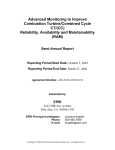
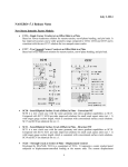
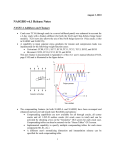
September 29, 2011 NASGRO v6.2 Release Notes NASFLA Additions and Changes New Stress Intensity Factor Models (also in NASSIF and NASCCS) • TC17 – Through Crack at Edge Notch in Plate (Univariant WF) o This stress intensity factor (SIF) solution is valid for a crack at the tip of an edge notch of arbitrary shape. Two common types of notch shape are supported in the GUI (an angular straight-edge notch and an elliptical notch) for a very wide range of geometry parameters. Stresses can be applied as remote tension/in-plane bending or (un-cracked) crack plane stresses. TC17 Angular Notch TC17 Elliptical Notch 1 • TC18 – Through Crack(s) at Offset Embedded Slot or Elliptical Hole in Plate (Univariant WF) o This SIF solution is for a through-thickness crack (or two symmetrical throughthickness cracks) at the notch tip(s) of an (offset) embedded slot or elliptical hole in a plate. A wide range of geometry parameters is allowed. Stresses can be applied as remote tension/in-plane bending or (un-cracked) crack plane stresses. TC18 Embedded Slot TC18 Elliptical Hole 2 • TC19 – Through Crack at Offset Hole in Plate with Broken Ligament (Univariant WF) o This SIF solution is for a through-thickness crack at a hole in a plate with one of the net sections completely broken through. o This crack case can be used to describe a continuing damage scenario after the short ligament in the TC13 crack case is broken through and a through-thickness crack initiates at the opposite side of the hole. The broken ligament is represented by two parallel edge surfaces with an infinitesimal gap. Stresses can be applied as remote tension/in-plane bending or (un-cracked) crack plane stresses. TC19 Broken Ligament 3 • TC13 – Through-Crack(s) at (Offset) Hole in Plate: Addition of In-Plane Remote Bending Capability Previously, stresses could be applied to crack case TC13 only as local crack plane stresses or as remote uniform tension. Based on the algorithm used for new crack case TC18, it is also now possible to apply remote in-plane bending stresses to TC13. TC13 now accepts a remote in-plane bending stress, S2 • TC16 – Through-Crack In Thin Curved Stiffened Panel with Bulging: Addition of Capability to Interpolate for Rivet Spacing Previously, when choosing to use the Rooke & Cartwright correction in crack case TC16, the user was restricted to a choice of three rivet spacing ratios (d/L): 1/3, 1/6, and 1/12. Now, in NASGRO v6.2, the radio button choices for these three d/L ratios have been replaced by a text input box that removes the restriction of using only these three d/L ratios and enables the user to input any d/L value that he wishes as long as 1/12 ≤ (d/L) ≤ 1/3. This capability was implemented by performing two successive Hermite polynomial 1-D interpolations, first on the stiffness ratio and then on the rivet spacing ratio. No extrapolation is allowed and an error message is displayed if the input d/L value is outside the 1/12 or 1/3 bounds. 4 New Options for Treatment of Negative Pin Load (Bearing Stress, S3) For crack cases in which pin loads (bearing stresses) are present, the treatment of negative pin loads was modified to allow the user to specify the option for computing K. These options appear on the Geometry page of the NASFLA GUI as shown below and pertain only to bearing stresses (S3): This change pertains to the pin-load crack cases: TC03, TC04, TC05, TC10, CC02, CC03, CC04, CC07, SC11 and SC12. The first option (compression clipping) uses only the positive side of the cycle, setting negative Ks equal to zero. This is a new option and is now the default; it is deemed more realistic than the second option. The second, more conservative option is to use the full range of K (from a negative minimum to a positive maximum K) and it is still available. The third option, which splits the full range into two independent cycles (one from zero to |Kmin| and the other from zero to Kmax), is available only for TC03, TC05 and TC09, with TC09 having only this option available. In NASGRO v6.1 and earlier, some models (the lugs, TC04 and CC03) used compression clipping, others used the full range approach (CC04, CC07, SC11 and SC12), and still others used the two sign-independent cycles approach (TC03, TC05), while TC10 and CC02 used a mixed approach. This caused inconsistencies when comparing results and was confusing. In NASGRO v6.2, the compression clipping option is now the default; however, the full range approach is also available. The capability to use the third option was retained in v6.2 for those models that previously had it (TC03 and TC05). The calculation for TC09; however, remains unchanged from v6.1 and only has the third option available. See the summary table below for additional details. Note that previously existing input files (nasfla.in) created with earlier NASGRO versions will be loaded into the v6.2 NASFLA GUI retaining the previously run option, if available. Otherwise, the NASGRO v6.2 default option will be used. 5 Improved Tabular Fatigue Crack Growth Rate Data Capabilities The capability to input fatigue crack growth rate data in the form of tabular da/dN-∆K data sets was completely revised and improved in NASFLA for v6.2.NASGRO v6.2 provides three kinds of tabular da/dN approaches: 1) 1-D table of da/dN vs. ∆K; 2) 1-D table of da/dN vs. ∆Keff; 3) 2-D table of da/dN vs. ∆K and R. The 1-D table of da/dN vs. ∆K option is for a single R-ratio and is available only for the noninteraction crack growth model. The 1-D table of da/dN vs. ∆Keff option applies to only the strip yield model. For each of these 1-D formats, a choice of two interpolation schemes is available (piece-wise linear or Hermite polynomial). When using the 1-D table ∆Keff option with strip yield, an additional option is now available that allows the user to represent the behavior in the threshold and instability regions in the form of the NASGRO or FASTRAN equations (with the default being neither, i.e., just using the tabular data). A view of the NASFLA material tab GUI for the 1-D table and ∆Keff option is shown below. Previously, the 2-D da/dN data tables consisted of two different “data formats”, one using the same da/dN values for all R and the other using a different set of da/dN values for each R. In v6.2, there is now only one (high-level) choice of a 2-D table in the “data format” pull-down menu; however, the same/different da/dNdata types are now sub-options once the 2-D data format is chosen. This is illustrated in the screen shot of the NASFLA material GUI shown below. This figure also shows the new interpolation schemes that have been implemented for 2D tabular data for NASGRO v6.2. Interpolation for R has three options: piece-wise linear (new default option), cubic spline (the previous default option) and Walker. Walker interpolation logic is used to extrapolate if a cycle goes beyond the bounds of the user-supplied R values, regardless of which R interpolation scheme is selected. Interpolation for ∆K has two options: 6 piece-wise linear (default) and Hermite polynomial. Appendix A of the User’s Manual provides extensive detail describing the implementation of the interpolation schemes as well as an overview of how NASGRO expands the user-specified table into a uniform 2-D table for use in the crack growth analysis. Plotting capabilities were added to NASGRO v6.2 to display user-supplied tabular da/dN∆Kdata. These capabilities allow the user to plot da/dN vs. ∆K data, including the original data points, the interpolation curves for the table stress ratios, and the interpolation curves for additional user-specified stress ratios. The GUI also allows the user to plot the interpolation curves of ∆K vs. R at each of the specified da/dN levels. The number of tabular data points that can be input have been increased: • For 1-D tables, the maximum number of rows was increased from 25 to 50 For 2-D tables, the maximum number of rows in the da/dN table with different da/dN set for each stress ratio was increased from 25 to 50, and the number of rows in the da/dN table with same da/dN set for all stress ratios from 25 to 450 Additional changes to the tabular data capability include: A different approach to consolidate user-supplied da/dN tables with different da/dN set into a uniform 2-D table. The consolidated uniform 2-D table, on which crack growth calculation is based, retains all the user-specified da/dN entries in the original da/dN tables, and shares the same da/dN set for all the stress ratios. 7 Capabilities to check if user-supplied da/dN curves for different stress ratios cross or not. The characteristic parameters of the Walker interpolation logic (the Walker exponents) are calculated before crack growth analysis for better computational efficiency. Implemented a methodology to adjust computational error from interpolation for stress ratio, eliminating negative slope of da/dN vs. ∆K curve. Changed and extended the rules of access to tabular da/dN capabilities. The 2-D table of da/dN vs. ∆K and R option has been extended to work with Willenborg retardation models. It is now accessible by the non-load-interaction model, the Boeing constant closure model, the generalized Willenborg model, and the modified generalized Willenborg model. New Temperature Interpolation Scheme for Fatigue Crack Growth Data The optional temperature interpolation algorithm, which predicts the FCG behavior at intermediate service temperatures bounded by discrete temperatures where the user has specified material properties, has been completely revised in NASGRO 6.2a. The new interpolation scheme is based on common da/dN values instead of common ∆K values (as used previously). This new approach resolves some potentially serious unstable interpolative problems that could occur near the threshold and instability regimes in the previous versions. In the Paris regime, the new approach will give similar, but not always identical, results to the previous approach. Illustration of FCG Curves Interpolated between User defined Curves at T1 and T2 8 Efficiency Improvement for Large Long-Block Spectrum Files The internal algorithms for reading and storing data from long-block spectrum files have been revised. The new algorithms can substantially reduce total computation time for NASFLA analyses using very large spectrum files. Improvements to Calculation Modes for Computing Initial Crack Size or Scale Factor A new solution algorithm was implemented for the two “inverse” calculation modes that allow the user to compute an initial flaw size given a target life and to compute a scale factor multiplier on the spectrum given a target life. These alternate calculation modes are available via the “Options” item on the NASFLA toolbar: In making the inverse solution algorithm more robust, there were a series of improvements and bug fixes made including: • A new, more accurate, convergence criterion was implemented such that the relative error between the actual calculated fatigue life (in cycles) and the target life is less than one percent. (In previous versions of NASGRO, the convergence criterion was based on schedules and could be very inaccurate depending on the content of the schedule.) • Capability was added to perform these two types of inverse calculations for 3-dof and 4dof crack cases. • Revised output formats in the .out1 file. Implementation of FASTRAN Crack Growth Program The FASTRAN computer program is a specialized fatigue crack growth analysis tool developed by J. C. Newman, Jr. FASTRAN performs the same basic function as NASGRO—evaluate fatigue crack growth in metallic structures as a function of cyclic applied loads, crack and component geometry, and material properties. However, FASTRAN uses a unique modified Dugdale strip-yield model to simulate plasticity-induced crack closure in the vicinity of the fatigue crack tip for improved accuracy in the prediction of load ratio, load history, and crack size effects. The existing strip-yield module in NASGRO, which is called STRIPY, has similar functionality to FASTRAN but many small differences in the details. 9 The most recent version of FASTRAN (5.3) has been interfaced with the current version of NASGRO and is now included in NASGRO v6.2 in a semi-independent form. FASTRAN cannot currently be executed in NASGRO through the NASGRO GUI. In order to execute FASTRAN through NASGRO, the input deck must be manually generated directly from available NASGRO NASFLA and FASTRAN input decks, and the program must be executed interactively in the MS-Windows system command windows (so-called “batch” mode). The description of these two steps (generating input decks and program execution) is described in the new Appendix Y of the NASGRO Reference Manual. A complete User’s Manual for FASTRAN 5.3, including a complete description of the input file structure, is also included. The NASGRO development team plans to integrate FASTRAN into the NASFLA GUI and to enable many NASGRO features to be used with FASTRAN (and vice-versa) in future years, subject to available funding. Linking Excel to NASFLA Beginning with NASGRO v6.2, several customized Excel worksheets are provided (in the “nasfla/excel_templates” subfolder) that accept input for a number of NASGRO crack cases. These worksheets write NASFLA GUI input files, call the NASFLA GUI to read these input files, run crack growth calculations in the background, and finally pipe the computed results back to Excel in the same format used when a user selects saving “ALL calc’d data to csv file” after a normal, interactive GUI session. The objective of enabling access to NASFLA in this mode is to provide a means whereby NASFLA can be run quickly from within Excel for simple geometries, material options, and load sequences. These worksheets operate on a reduced set of input options and are not intended to reproduce a complete input interface within Excel. Details about how to run NASFLA interactively from within Excel are provided in Appendix Z of the User’s Manual. The following list shows the input options and parameters that are currently available. • • • • Geometry: o Applicable to models TC01, TC03, TC05 and SC01 o input for basic parameters (crack size, thickness, width, hole diameter, etc.) o crack size input restricted to “User entry” only; no “NASA std NDE” method specification Material: o non-interaction model only o NASGRO equation constants from the NASGRO material file only o material input via NASGRO material ID only; no manual editing of constants Load blocks: o load block type “Input cycles and stresses manually” only o up to 10 blocks of up to 10 steps each Print options: o no restrictions 10 Options not listed above are considered advanced options and as such are not available for user modification from their default values. The figure below shows the input worksheet for crack case TC01 as an example. Other New or Changed NASFLA Items: • When batch processing a list of input files, a single message window will now be presented, giving the user the option to save all older format input files in the new format. This allows a long list of input files to be run without any user intervention. Previously, a window would be presented for each old format input file encountered, which slowed down this automation significantly. Additionally, if the user opts to save old formats, a list of those saved files will now be presented at the end of processing, in the output window. (Also in NASSIF, NASCCS & NASGLS.) • Whenever a material file parameter value is changed manually by the user, a note will now be displayed at the top of the material tab to indicate this change. This note makes clear that at least one value is no longer a file value (which is needed since the "data source" field will still show "material file"). Additionally, when a material plot is performed on changed values, the plot title will show as "NASGRO EQN curve". Previously, the title was "Basic Fit" to indicate the NASGRO equation curve generated 11 used the material file constants and was fitted to the data, both of which are no longer true once any parameter value has been altered. • Labels on the Output Options tab: Block interval for printing steps in a block and (if a non-zero choice is made) the labels for the boxes below it have been changed to make clear that quantities, like maxima, when printed are not for individual step maxima, but rather the running block maximum to the end of the step being printed. • The text displayed under the Cth value option on the Material tab was altered to be the input cell value throughout to inform the user that if the value in this cell is changed during input, that it is the new value that will apply to the calculation and not the original material file value. • Changed the label of the Material Tab radio box from "Cth value option" to "Cth value used in analysis" to make clear that this setting is used for the analysis only, and is not used in the “View curvefit" button's plots. • The ability to allow the user to change Cthm, the fanning factor for negative stress ratios, has been restored in v6.2f after temporarily suspending this ability in v6.2 beta. • The Cth value option: \"0 Initially\" has been removed from use for 3D and 4D crack cases. • For crack cases CC08, CC11, EC02, EC05, SC17, SC18, TC11, TC12, TC13, TC17, TC18, and TC19, the output echo of user-supplied stress pairs when using the OPS option with univariant stress input tables has been improved. All original user-supplied stress pairs are now echoed in the output display. Previously, a reduced number of stress input pairs was shown. (Also in NASSIF.) • For crack cases CC02, CC03, CC04, CC07, SC11, SC12, TC03, TC04, TC05, TC09, and TC10, the net section stress check for S3 vs. YS or flow stress was removed for pinloading (bearing stress). (Also in NASSIF & NASCCS.) • For crack cases SC11, SC12, and SC18, the geometry limits displayed in the GUI were updated and some redundancies were eliminated. (Also in NASSIF, NASCCS & NASGLS.) • For crack cases TC13 and TC18 the correction factor applied for converting from a onecrack solution to a two-crack (symmetric) solution was updated to include an additional boundary correction factor. The results have been validated against FE results. (Also in NASSIF.) • Crack cases TC17, TC18, TC19: Revised Appendix B to include net section yield (NSY) analysis. (Also in NASSIF, NASCCS & NASGLS.) 12 • Crack case SC13: Added a warning message indicating solution inaccuracy if the ratio of fillet radius 'r' to bolt major diameter 'D' (r/D) is outside the numerical range of [0.005 ... 1.0]. (Also in NASSIF, NASCCS & NASGLS.) • Removed the "View curvefit" button from the Material tab for non-NASGRO material selections. This button provided no functionality for these choices and only displayed the message "Material plots still under development for this combination of material source and format." when clicked. This button remains active to provide plotting functionality for NASGRO material files (both temperature and non-temperature) using the "NASGRO equation constants” Data format. • For 3D and 4D crack cases: (SC17 (non-symmetric), SC18 (non-symmetric), SC19, EC02, EC04, EC05), the selection of "0 initially" for the "Cth value option" radiobox on the Material tab is no longer allowed. In these cases, this option will be grayed out and the radiobox choice will default to "0 throughout". Any previously created input files for these cases containing this setting will be loaded with "0 throughout" instead and the input file will be resaved. • Upon completion of an analysis, the GUI will now automatically display the Output Summary information in the display window on the Computations tab. Previously, the user was required to manually click the “View Output Summary” button for this information to be displayed. • Enhanced 2-D tabular da/dN plotting capabilities to plot user-provided da/dN vs. dK curves even if the curves intersect. • Improved compounding capabilities, issuing error messages to the out1 file if userspecified crack sizes are outside the bounds of the compounding tables. (Also in NASSIF.) Changes and Additions to NASFLA Materials (Curve Fits): • Altered the descriptive text for each material in each of the user multi-temperature template files (in US customary and in metric units) to be in both systems of units, allowing the user when making choices to view the textual part in both systems simultaneously. • Changed the NASGRO equation curve fits constants for 7050-T7451 aluminum in L-T and T-L orientations based on newly acquired data (Material IDs M7GJ11AC1 and M7GJ12AC1). • NASGRO equation curve fit was added for AerMet 100 steel (E1NB18AC1). • The materials file ID E1NB23AB1 (AerMet 100) was changed to E1NB18AB1 to make it consistent with the data upon which the fit was based. 13 • NASGRO equation curve fits were added for the following aluminum alloys: o 2524-T3 sheet in L-T orientation (M2KN11AC1) o 2524-T3 sheet in T-L orientation (M2 KN12AC1) o 2524-T3 sheet in L-T & T-L orientations (M2KN13AC1) o 2050-T84 plate in T-L & L-T orientations (M2SA13AC1) o 2050-T84 plate in S-L orientation (M2SA15AC1) o 6156-T6 sheet in T-L & L-T orientations (M6GB13AB1) • NASGRO equation curve fit was added for 2014-T6 aluminum forging (M2AD23AB1). • NASGRO equation curve fit was added for ZE41A-T5 magnesium casting (T2NA51AC1). • Changes were made in the materials files, using "M2KN" in the material ID for 2524-T3, and retaining "M2LA" exclusively for 2618-T6. • A typographical error in the value of Bk in the material database files (NASMFC & NASMFM) was corrected for 2524-T3 (ID = M2KN11AC1). • Corrected the curve fit constants for two Titanium alloys, material IDs: P3EA13AB1 and P3EC13AB1. NASFLA Fixes • Crack case EC04: o Inconsistent results fixed for remote bending and user-defined bending. o Inconsistent results fixed with crack case EC05 for univariant stressing. • Modified the transfer of NASA standard NDE flaw size information from the GUI to the DLL, now passing the actual initial flaw sizes in lieu of the descriptive information transferred earlier. This change, together with corrections made to the DLL, ensures that calculations performed using the NASA standard NDE option are based on crack sizes that correspond to MSFC-STD-5009, the current standard. • NASFLA GUI would crash when attempting to load user material fits that had been created in NASMAT, due to NASMAT adding blank values for K1e, K1c, AK, Bk. (when choosing "Enter Kc or K1e directly"). NASMAT will no longer add blank values for these constants. • Loading incomplete input files (with no material data) at times disabled the GUI. 14 • Crack cases SC01-SC05, SC11, SC12, SC15, SC17-SC19: "NDE depth" radiobox was not being removed from screen when "Initial flaw option" was reset to "User entry", or when "NDE Type" choice was reset to "Click to display choices". • Crack cases SC07, SC08, SC13, SC14: If "Initial flaw option" is set to "NASA std NDE", changing the "Crack Tip Input" radiobox would not update the Geometry Grid to contain the correct NDE flaw sizes for the selected crack tip. • Crack case CC11: a bug encountered when computing the limit load was fixed. • Crack case EC02: when running multiple aspect ratios, the results, except the first one were incorrect. This resulted from one of crack sizes exceeding the solution limits. The scenario triggered a transition flag and as a result provided SIF solutions based on incorrect crack model. • After an analysis, when exclusively viewing any "Input:..." choices on the Computations tab, many extra blank lines were added to the display window in error . • Crack cases SS01-SS12: Removed "Initial flaw option" radiobox, since the "NASA standard NDE" choice for initial flaw size should not be offered for these cases. • Corrected the screen layout for the Material tab selections of the Strip Yield crack growth model and the NASGRO equation constants to avoid overlap of controls for Strip Yield transition grid and Threshold Alpha. • Changing the Crack Growth Model selection on the Material Tab did not always correctly repopulate the Data Format dropdown box with all possible selections. • Crack case CC09: A bug that caused the long block feature to malfunction with this model has been fixed. • When loading tabular 2-D material data using different da/dN sets for each R from file, some rows were not loaded into the grid correctly if they contained leading blanks. • The FAD failure criterion option has been fixed to work with 1D FCG table, 2D FCG table, and Walker equation constants data formats. • GUI sometimes incorrectly displayed the NASGRO equation materials for selection instead of the (correct) Walker equation materials, when "Chang-Willenborg" was chosen as the Crack Growth Model. • User was not prompted to resave input file when Crack Growth Model selection was changed. Additionally, the default material parameter values for Willenborg models' "Shutoff Overload Ratio" (3.0) and "Phi0" (0.4) were incorrectly erased when a new project was chosen or an existing GUI input file was loaded. 15 • Corrected column position of "a over c" data in output viewing window. • Output data column headers initially missing when selecting all details to show on the Computations tab. • Proper headers for out2 and csv files were missing when FAD analysis option was used. • For crack case EC05, the crack tip designations in the failure message for this model were misleading when the FAD analysis option was used. The output has been modified to be consistent with the crack tip designations shown in the GUI bitmap. • FAD output files .out4, .out5, and Newman TPFC output file .out6 are now all saved back to the input file directory after computations have completed, and are renamed with the project input file name (similar to .out1 and .out2). • On the Computations tab, if any items in the "Select Details to Show" listbox were highlighted prior to re-running an analysis, those selections were erroneously cleared, requiring the user to unnecessarily re-select them for repeated viewing. • Choosing Shakedown correctly forces OPS on, but did not automatically increase the size of the user input stress grids. • Default values for Schedule and Block interval for controlling output frequency were missing after some input files were loaded. • User material IDs longer than 15 digits caused intermittent GUI problems. • When plotting material IDs, comparison plots containing more than six IDs caused plotting problems. • Material file values were reloaded in error whenever "Options, Units" was selected to change units in the GUI. • For crack case TC03, an error was corrected in the conversion of pin-load/bearing stress (S3) during transition from TC03 to TC02. • The material plots for Basic and Comparison fits were modified to use the screen value for "Threshold Alpha." Previously, the default value of 2.0 was used, regardless of what was typed on screen. • Corrected errors in calculation of stress intensity factors and crack growth rates for embedded (4-D) cracks (EC02, EC04 and EC05) subjected to load steps with large number of cycles. • Changes were made to the closure function forcing it to remain non-negative everywhere in its domain of definition, avoiding possible discontinuities in Keff. The only 16 calculations that this change can potentially affect are those involving load steps with highly negative [< -2] stress ratios. • Corrected calculation of the under-load ratio for the 2D modified generalized Willenborg model. • Some crack sizes were not set properly for the calculation of stress intensity factors and crack growth rate during crack growth analysis for 3D cracks. • Fixed an output error (in SC01) wherein crack-tip stress-intensity factors in excess of Keac did not apparently trigger failure, despite the calculated life being consistent with earlier (v4.22) correct versions. • Removed previous file size limit of 2000 lines for Alternative 2D stress input files. • Crack case TC11: corrected the calculation of compounding factors when using the symmetric crack option. • The correct values for fatigue crack growth threshold will now be properly written to the out2 file for 2D tabular da/dN capabilities. • When changing units (using Main Menu: Options, Units), the following Kc fields shown on the Material tab for "New Data" for each selection of the radiobox: "Through crack toughness computed from:" were not being converted: Kc, K1c, and the \'Kc vs. thickness\' table. • After a material has been selected, if the Material Selection dialog is re-run, it was possible to undo the previous Material Category, Alloy, and Heat Treat selections, then return to the Material tab by clicking OK, with no selection for any or all of these three choices. This enabled an input file to be saved without a chosen material category/alloy/heat treat, which would then load incorrectly due to this missing data. • For multi-temperature analyses, only the NASGRO format long block file type may now be selected, since this is the only format that allows for temperature data. • After changing temperature-based material selections on the Material tab, it was possible that the stress values in the Load Blocks grid displaying the BLOCKT file data could be manually changed. • Improved the capabilities of crack size limits to include intra-load step checking of crack size in addition to the inter-load step checking already performed. • Elapsed execution time is now properly calculated for very small durations. 17 • User-entered tension and compression stress data (files, grids) can now be visualized in the GUI, both with and without the OPS option, by using the Geometry tab's “Plot Stresses" button. (Also in NASSIF.) • Overcame a 2000-point limit on alternate-stress-format arrays by raising it to 2500, and rewrote the OPS routines to fix an error encountered when very small numbers are compared. (Also in NASSIF.) • Corrected internal library support issues within the OPS routines, which prevented some intermediate plot files to be produced, resulting in a GUI crash during plotting. (Also in NASSIF.) The following NASFLA fixes also pertain to NASSIF and NASCCS: • Crack case SC04: external crack fails right away no matter what initial crack size is specified. • Lay out at least one interpolation point between any two raw data points when plotting user-specified beta factors for crack case DT01. • Interpolation outside the parameter limits of the tabulated data was terminated with an error. The fix ensures the computation will not be terminated when such an out-of-bound scenario is encountered. • Crack case TC18: o Corrected bitmap image regarding the definition of crack length 'c'. The correct measurement begins at the notch tip, not from the center of the root radius, as previously depicted. o The SIF solutions were under-predicted for cracks at the notch tips of elliptical holes with e2 > e1. This problem has been resolved by interpolating between the crack-at-hole solution and the crack-in-plate solution. • For crack cases TC17 and TC18, a description line was added to the NASGRO output files to indicate which notch shape (angular straight edge or elliptical) was specified. • For crack case TC12 the incorrect handling of internal stress quantity indicators had prevented plotting of stress grid data. This has been fixed. • For crack cases SC11, SC12, and SC18, when loading an input file containing SIF compounding data, the number of SIF compounding grids was not being properly assigned from the saved values, due to the "c then a" display configuration used for these geometries. This has been fixed. 18 • When loading an input file containing SIF compounding tables, a warning message would sometimes be displayed, in error, stating the table currently displayed was outside the new range. This has been corrected. • For crack cases TC17 and TC19, an error was corrected in the net section stress calculation for remote tension and bending. • For crack case DT03 an error in the batch file was corrected that prevented an analysis to be run if the number of columns contained in any geometry table was greater than 13 and a multiple of 7. (Also in NASGLS.) • The "input modified" flag was being erroneously set by using the "Show tables for" radio box on the GeomTables tab for crack case DT03 and all crack cases that use SIF Compounding. This radio box enables data or SIF Compounding tables for a specific crack tip to be shown and does not alter data. As such, this flag should not be set. (Also in NASGLS.) • For crack case CC08, an incorrect geometric check in the code caused erroneous "NAN" F0 values to be printed in the out2 file. This has been corrected. (Also in NASGLS.) • Crack cases CC08, SC18: If either crack case CC08 or SC18 is selected, followed by selecting crack case TC13, then reselecting either CC08 or SC18 again, the initial crack plane stress definition choice of "Remote tension" remained as TC13's choice: \"Tension,bend\". This problem has been corrected, and now upon reselection of the original crack case CC08 or SC18, this choice will be correctly relabeled back to \"Remote tension\". (Also in NASGLS.) • Crack case CC08: o Fixed an error which in the presence of an out-of-bounds crack resulted in an attempted de-allocation of unallocated memory. (Also in NASGLS.) o Fixed an improper out-of-bounds validity check, which prevented normal functioning of this crack case when a/c = 0.5. (Also in NASGLS.) • Crack case TC11: Fixed an initialization error which prevented normal functioning of this crack case when run as a symmetric crack with symmetric stressing. (Also in NASGLS.) • Crack cases CC04, CC07: Adjusted bitmap images to properly convey to the user that these solutions assume that the stresses applied to the lower surface are remote from the crack. (Also in NASGLS.) • Fixed a stress gradient reversal error in EC05, which result in reversals of applied and residual stress in the output, although the calculations themselves were correctly done. • Crack case PS01: o Removed the \"Stress label\" radiobox from Geometry tab. This was previously used to assign a stress label for display in various outputs but was confusing. This 19 output display will now be hardcoded to "S0", conforming to the existing stress labels throughout the GUI, which are also "S0". The Geometry Grid field "Stress description" will continue to be used to describe the stress. (Also in NASGLS.) o The expression shown in the crack case's bitmap has been revised to use superscripts (instead of two asterisks) to more clearly depict exponents.(Also in NASGLS.) • Removed crack case DT04. (Also in NASGLS.) NASSIF Fixes • Crack case SS12: Stress was not properly computed (was zero) when "Load input" was set to "Pin load, P". • Crack case TC11: o Errant "Stress file does not exist" message displayed and program crash occurred. o Crack lengths were displayed incorrectly in the output, showing only the final crack length, when computing correction factors. • Crack cases TC13, TC17, TC18, TC19: Output Options tab showed incorrect stress quantity labels for the crack plane stress definition of "Tension, bend". • Crack case TC15: Screen layout error for SIF Compounding checkbox. • Crack case: Corrected an error in the OPS internal routines which prevented analysis results from being produced. • Crack cases CC09, CC10, EC04, SC19: For bivariant analyses with user-provided stress input files, abnormal behavior in calculations was observed for a/c values near 1.0. This has been corrected. • Crack case CC11: Corrected an internal error handling issue which prevented analysis results from being produced. • Crack cases EC04, EC05: Corrected a batchfile format error when writing crack size data, preventing analyses from being run. NASCCS Fixes • Crack case CC11: Stress grid input was missing from the batch file, preventing an analysis to be run. 20 NASMAT Additions • Added crack growth data for the following materials: Steel: C4DF21AB01 – 4340 (190 UTS) Aluminum Alloys: M2AD23AC01A – 2014-T6 forging M2KN11AC01 – 2524-T3 sheet M2KN12AC01 – 2524-T3 sheet M2SA11AC01 – 2050-T84 plate M2SA12AC01 – 2050-T84 plate M2SA15AC01 – 2050-T84 plate M6GB11AB01 – 6156-T6 sheet M6GB11AC01 – 6156-T6 sheet M6GB12AB01 – 6156-T6 sheet M6GB12AC01 – 6156-T6 sheet M7GJ11AC01C – 7050-T7451 plate M7GJ12AC01D – 7050-T7451 plate Magnesium Alloys: T2NA51AC01 – ZE41A-T5 casting T2NA52AC01 – ZE41A-T5 casting T2NA54AC01 – ZE41A-T5 casting T2NA55AC01 – ZE41A-T5 casting NASMAT Changes • Removed certain errant data points from the following two Aluminum material IDs: M2AD23AB01A (2014-T6 forging) and M7PF11AB01B (7150-T7751 plate). • Removed the data for the following Aluminum material ID: M2AD23AB01B (2014-T6 forging). • Changes were made in the materials files, using "M2KN" in the material ID for 2524-T3, and retaining "M2LA" exclusively for 2618-T6. • The material ID for data added in v6.2a for 7050-T7451 Aluminum alloy has been changed to M2GJ12AC01D. 21 NASMAT Fixes • Fixed crash when attempting to save "da/dN-DK" data to the user file that had been converted from "a vs. N" data. • Corrected problems that occurred when adding material fits to user material files. Existing IDs weren't being updated, new entries and IDs were not added in proper order, and GUI would issue debug alert messages and crash. • When entering da/dN-DK data or a vs N data via a text file, the use of a 'T' or 't' in the Text File Information dialog, to represent a Tab delimiter, has been fixed and now functions properly. NASFORM Fixes • The NASFORM GUI would not display the NASGRO user manual if the programs were installed to any location other than the default location suggested by the installer. This has been fixed. Installation of NASGRO Data Files It is now highly recommended for Windows Vista and Windows 7 users to NOT install the NASGRO data files in the “C:\Program Files” location. These two operating systems impose severe restrictions on programs’ ability to write to data files located in the “Program Files” folder or its subfolders. Therefore, "My Documents" or “Documents" is now suggested as the default installation path for the NASGRO data files installer as shown in the data files install screen on the right. Appendix I (the installation instructions) has been revised accordingly and the data files installer’s dialog box notifies the user of this recommendation. 22