1
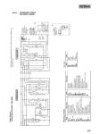
Operations Manual
Super 12 bit AD/DA card
Operations Manual
Super 12 bit AD/DA card
CHAPTER 1
CHAPTER 2
INTRODUCTION
UNPACKING INFORMATION
The super 12 bit A/D-D/A card is a high precision data conversion
system for PC/486, Pentium, or compatibles. It contains two 12 bits
digital to analog channel with unipolar or bipolar format, and
sixteen/eight 12 bits (single-ended / differential) analog to digital
channels conversion with unipolar or bipolar format.
Check that your super 12 bit A/D-D/A package includes the
following items:
•
•
•
•
•
The features of the super 12 bit A/D-D/A board are:
D/A:
• 12 bits resolution
• Output channel : Two
One Standard
One optional
• Output voltage setting
Unipolar : 0V to 2.5V, 0V to 5V, 0V to 10V
Bipolar : -2.5 to 2.5V, -5 to 5V, -10 to 10V
Super 12 bit A/D-D/A board.
Demo Program.
Data Capture Software Manual with Disk.
User manual.
Warranty form.
A/D:
• 12 bits resolution
• Input voltage range
Unipolar : 0V to 2.5V, 0V to 5V, 0V to 10V
Bipolar : -2.5 to 2.5V, -5 to 5V, -10 to 10V
• Channel number
16 channels single-ended input.
8 channels differential input.
I/O port address selectable
LED indicates when adapter is operating.
DECISION Computer International
1
2
DECISION Computer International
Operations Manual
Super 12 bit AD/DA card
Operations Manual
CHAPTER 3
Super 12 bit AD/DA card
CHAPTER 4
HARDWARE INSTALLATION
HARDWARE CONFIGURATION
Your super 12 bit A/D-D/A card is designed to be inserted in any
available slot in your PC/486, Pentium or compatibles. In order to
gain access to the expansion slots, follow the steps listed below:
Before you use the A/D-D/A card, you must ensure that the port
address and jumper are set correctly, the proper settings for the A/DD/A card are described in the following:
1. Turn off all power to your computer and all peripheral
devices before installing your industry card.
2. Remove the cover of the computer.
3. Insert the SUPER 12 BIT AD/DA CARD into any available
slot. Make sure the adapter is firmly seated in the chosen slot.
4. Replace the cover of the computer.
5. Connects the expansion cable to 25 pin connectors.
6. Turn on the power of your computer.
DECISION Computer International
3
4
DECISION Computer International
Operations Manual
Super 12 bit AD/DA card
Operations Manual
Super 12 bit AD/DA card
4.1 I/O Port Address
The I/O port address are &H170-17F or &H160-16F selectable:
1. 170/160 : Output A/D channel number. (low nibble)
2. 171/161 : Clear A/D register.
3. 172/162 : Input A/D low byte data. (8 bits)
4. 173/163 : Input A/D high byte data. (low nibble)
5. 174/164 : Output D/A low byte data. (channel 1/8 bits)
6. 175/165 : Output D/A high byte data. (channel 1/low nibble)
7. 176/166 : Output D/A low byte data. (channel 2/8 bits)
8. 177/167 : Output D/A high byte data. (channel 2/low nibble)
9. 17A/16A A/D conversion loop. (low)
10.17C/16C : A/D conversion loop. (high)
4.2 Jumper Setting
1. I/O Port Address
1
2
JP8
JP8 is used to select I/O port address
JP8
short
open
DECISION Computer International
5
6
Address
H170 - 17F
H160 - 16F
DECISION Computer International
Operations Manual
PORT
Port 0
Port 1
Port 2
Port 3
Port 4
Port 5
Port 6
Port 7
Port 8
Port 9
Super 12 bit AD/DA card
CASE 1
H170
H171
H172
H173
H174
H175
H176
H177
H17A
H17C
CASE 2
H160
H161
H162
H163
H164
H165
H166
H167
H16A
H16C
Operations Manual
JP3-1
short
open
JP6-1
short
open
open
JP6-2
open
short
open
JP1
1 2
Short 1: Single-ended mode
Short 2: Differential mode
polar
bipolar
unipolar
JP6-3
open
open
short
scalar
2.5V
5V
10V
JP5
1 2 3
JP1 is used to select unipolar or bipolar of D/A channel 1 output
voltage, and JP5 is used to select voltage scalar of D/A channel 1
output voltage.
JP7 is used to select single-ended or differential mode.
3. A/D Input Voltage and Scalar
JP3
1 2
JP3-2
open
short
4. D/A Channel 1 Output Voltage and Scalar
2. Single-ended or Differential Mode Selection
JP7
1 2
Super 12 bit AD/DA card
JP1-1
short
open
JP6
1 2 3
JP5-1
short
open
open
JP3 is used to select unipolar or bipolar of A/D input voltage, and
JP6 is used to select voltage scalar of A/D input voltage.
JP1-2
open
short
JP5-2
open
short
open
polar
bipolar
unipolar
JP5-3
open
open
short
scalar
2.5V
5V
10V
5. D/A Channel 2 Output Voltage and Scalar
DECISION Computer International
7
8
DECISION Computer International
Operations Manual
Super 12 bit AD/DA card
JP2
1 2
1. select A/D unipolar and 0V to 10V scalar
JP2 is used to select unipolar or bipolar of D/A channel 2 output
voltage, and JP4 is used to select voltage scalar of D/A channel 2
output voltage.
JP4-1
short
open
open
JP2-2
open
short
JP4-2
open
short
open
Super 12 bit AD/DA card
In the following, we show some jumper setting examples.
JP4
1 2 3
JP2-1
short
open
Operations Manual
JP3
1 2
scalar
2.5V
5V
10V
JP6
1 2 3
3. select D/A channel 1 unipolsr and 0V to 5V scalar.
NOTE
1. The scalar range is from negative voltage to positive voltage
when bipolar is selected. Otherwise, the scalar range is from 0 to
positive voltage.
2. The full scalar voltage is the higest voltage dependent on your
scalar range selection.
3. Default settings are unipolar and scalar range is 10V.
DECISION Computer International
JP6
1 2 3
2. select A/D bipolar and –5V to 5V scalar.
polar
bipolar
unipolar
JP4-3
open
open
short
JP3
1 2
9
JP1
1 2
JP5
1 2 3
4. select D/A channel 2 bipolar and –2.5V to 2.5V scalar.
JP2
1 2
JP4
1 2 3
10 DECISION Computer International
Operations Manual
Super 12 bit AD/DA card
Super 12 bit AD/DA card
B. Differential Mode
4.3 D Type Connector Pin Assignment
A. Single-ended Mode (default setting)
Pin
Function
Pin
Function
1
+12V
14
-12V
2
D/A CH2 OUT
15
D/A CH1 OUT
3
GND
16
A/D CH15
4
A/D CH14
17
A/D CH13
5
A/D CH12
18
A/D CH11
6
A/D CH10
19
A/D CH9
7
A/D CH8
20
A/D CH7
8
A/D CH6
21
A/D CH5
9
A/D CH4
22
A/D CH3
10
A/D CH2
23
A/D CH1
11
A/D CH0
24
GND
12
GND
25
-5V
13
+5V
DECISION Computer International
Operations Manual
11
Pin
Function
Pin
Function
1
+12V
14
-12V
2
D/A CH2 OUT
15
D/A CH1 OUT
3
GND
16
A/D CH7-
4
A/D CH7+
17
A/D CH6-
5
A/D CH6+
18
A/D CH5-
6
A/D CH5+
19
A/D CH4-
7
A/D CH4+
20
A/D CH3-
8
A/D CH3+
21
A/D CH2-
9
A/D CH2+
22
A/D CH1-
10
A/D CH1+
23
A/D CH0-
11
A/D CH0+
24
GND
12
GND
25
-5V
13
+5V
12 DECISION Computer International
Operations Manual
Super 12 bit AD/DA card
Operations Manual
CHAPTER 5
4.4 VR Adjustment
VR1, VR2, and VR3 are used to adjust reference voltage of A/D and
D/A channel. To screw VR clockwise, the reference voltage will be
increased, otherwise to screw VR counterclockwise, the reference
voltage will be decreased.
VR number
VR3
VR1
VR2
Super 12 bit AD/DA card
SOFTWARE DIAGNOSTIC
5.1 Software
1. ADJU12.BAS
The ADJU12.BAS is used to adjust reference voltage, the factory
settings of VR resistors are adjust to full scalar voltage (10V).
port
A/D channel
D/A channel 2
D/A channel 1
After you run this program, the output voltage of D/A channel 1 and
channel 2 are set to full scalar voltage, so that you may screw VR2
and VR3 to adjust output voltage to full scalar voltage. To adjust
A/D channel, you may connect D/A channel 1 and A/D channel then
screw the VR3 until A/D input number equal to 4095.
2. AUTO12.BAS
Loopback test program.
3. ADDA12.BAS
Diagnostic program.
5.2 Diagnostic Test
1. Insert the demonstration media into drive, then copy diagnostic
program into your computer.
2. Key in the BASIC test program, then type run. (please refer
section 4)
3. The screen will display:
------------------------------------------------------------which selection do you want?
1. D/A MODE
2. A/D MODE
DECISION Computer International
13
14 DECISION Computer International
Operations Manual
Super 12 bit AD/DA card
------------------------------------------------------------4. If you select “1. D/A MODE”, pin 2 and pin 15 of D-type
connector will output 64 steps saw-tooth wave.
5. If you select “2. A/D MODE”, screen will display each value
(from 0 to 16383 of the 16 channel).
Super 12 bit AD/DA card
2. Digital to analog (D/A) procedure
(1) Output high byte (channel 1/low nibble)
OUT port + 5, Hdata
(2) Output low byte (channel 1/8 bits)
OUT port + 4, Ldata
5.3 Programming Techniques Under MS/DOS
(3) Output high byte (channel 2/low nibble)
OUT port + 7, Hdata
1. Analog to digital (A/D) procedure
(1) Output channel number to port
OUT port , channel
(4) Output low byte (channel 2/8 bits)
OUT port + 6, Ldata
(2) Clear register
OUT (port+1) , 0
5.4 BASIC Test Program
(3) Start convert
FOR I = 1 to 6
A = INP(port + 12)
NEXT I
FOR I = 1 to 8
A = INP(port + 8)
NEXT I
10 CLS: PORT=368
20 LOCATE 5,18: PRINT “ 12 BIT AD-DA CONVERSION
CARD”
30 LOCATE 6,18: PRINT “=======================”
40 LOCATE 9,20: PRINT “1. D/A CONVERSION DEMO”
50 LOCATE 11,20: PRINT “2. A/D CONVERSION DEMO”
60 A$=INKEY$: IF A$=”” THEN 60
70 IF A$=”1” THEN 200
80 IF A$=”2” THEN 400
90 GOTO 10
200 CLS
202 LOCATE 5,15: PRINT “D/A CINVERSION DEMO”
204 LOCATE 7,15: PRINT “OUTPUT WAVEFORM FROM D/A
PORT”
206 LOCATE 9,15: PRINT “PRESS ANY KEY RETURN MENU”
210 OUT PORT+4,0 : OUT PORT+6,0
(4) Read high byte (low nibble)
C = INP(port +3)
HB = (C/16 – INT(C/16)) * 16
(5) Read low byte (8 bits)
LB = INP(port + 2)
(6) Data
AD = HB * 256 + LB
DECISION Computer International
Operations Manual
15
16 DECISION Computer International
Operations Manual
Super 12 bit AD/DA card
220 FOR I = 0 TO 15
230 OUT PORT+5, I : OUT PORT+7,I
240 NEXT I
250 A$=INKEY$: IF A$=”” THEN 210
260 GOTO 10
400 CLS
410 FOR CHANNEL = 0 TO 15
420 GOSUB 550
430 B = INP(PROT+3)
440 C = INP(PORT+2)
450 D = (B-16*(INT(B/16))) *256 + C
460 PRINT “ CHANNEL= “; CHANNEL, “DATA= “:D
470 NEXT CHANNEL
480 PRINT:PRINT:PRINT
490 GOTO 410
550 OUT PORT+1,0
560 OUT PORT+0, CHANNEL
570 FOR I = 1 TO 6: A= INP(PORT+12):NEXT I
580 FOR I = 1 TO 8: A= INP(PORT+8):NEXT I
590 RETURN
Operations Manual
Super 12 bit AD/DA card
APPENDIX A
WARRANTY INFORMATION
A.1 Copyright
Copyright
2002,
2003
DECISION
COMPUTER
INTERNATIONAL CO., LTD. All rights reserved. No part of 12
BIT AD/DA CARD software and manual may be reproduced,
transmitted, transcribed, or translated into any language or computer
language, in any form or by any means, electronic, mechanical,
magnetic, optical, chemical, manual, or otherwise, without the prior
written permission of DECISION COMPUTER INTERNATIONAL
CO., LTD.
Each piece of 12 BIT AD/DA CARD package permits user to use
12 BIT AD/DA CARD only on a single computer, a registered user
may use the program on a different computer, but may not use the
program on more than one computer at the same time.
Corporate licensing agreements allow duplication and distribution of
specific number of copies within the licensed institution.
Duplication of multiple copies is not allowed except through
execution of a licensing agreement. Welcome call for details.
A.2 Warranty Information
DECISION warrants that for a period of one year from the date of
purchase (unless otherwise specified in the warranty card) that the
goods supplied will perform according to the specifications defined
in the user manual. Furthermore that the 12 BIT AD/DA CARD
product will be supplied free from defects in materials and
workmanship and be fully functional under normal usage.
DECISION Computer International
17
18 DECISION Computer International
Operations Manual
Super 12 bit AD/DA card
In the event of the failure of a 12 BIT AD/DA CARD product
within the specified warranty period, DECISION will, at its option,
replace or repair the item at no additional charge. This limited
warranty does not cover damage resulting from incorrect use,
electrical interference, accident, or modification of the product.
All goods returned for warranty repair must have the serial number
intact. Goods without serial numbers attached will not be covered
by the warranty.
Transportation costs for goods returned must be paid by the
purchaser. Repaired goods will be dispatched at the expense of 12
BIT AD/DA CARD.
To ensure that your 12 BIT AD/DA CARD product is covered by
the warranty provisions, it is necessary that you return the Warranty
card.
Under this Limited Warranty, DECISION's obligations will be
limited to repair or replacement only, of goods found to be
defective as specified above during the warranty period. DECISION
is not liable to the purchaser for any damages or losses of any kind,
through the use of, or inability to use, the 12 BIT AD/DA CARD
product.
DECISION reserves the right to determine what constitutes
warranty repair or replacement.
Return Authorization: It is necessary that any returned goods are
clearly marked with an RA number that has been issued by
DECISION. Goods returned without this authorization will not be
attended to.
DECISION Computer International
19