1
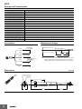
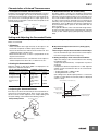
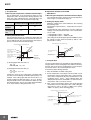
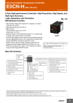
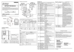
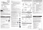
New Product
Infrared Thermosensor
ES1C
Achieve Superior Environmental Resistance and a Wide Measurement Range of
0 to 400°C.
• Flexible placement with slim cylindrical shape and long focus with
a distance of 500 mm and area diameter of 80 mm.
• The SUS body and silicon lens resist ambient operating temperatures of up to 70°C and resist dust and water to the equivalent of
IP67.
• Fast measurement with high-speed response of 100 ms/90%.
• Strong resistance to noise with output of 4 to 20 mA.
Refer to the Safety Precautions on page 6.
Ordering Information
Specification (measuring temperature range)
Model
0 to 400°C
ES1C-A40
Application Examples
Checking Temperatures for Fabrication and Molding Materials
Quality Control in the Thermal Sheet
Processing
Digital Temperature Controller
E5CN-@L
Digital Panel Meter
K3GN-ND@
Monitoring the Temperature of Liquid Crystal Glass Substrates
Checking the Drying Temperature in
Baked Coatings
Modular Temperature Controller
EJ1
Digital Panel Meter
K3HB-X
Do not use the ES1C in locations subject to rapid changes in ambient temperature.
Use a heat shield to suppress temperature changes if the ES1C is used in a location that is subject to rapid changes in ambient
temperature due to radiating heat or hot air.
1
ES1C
Ratings and Characteristics
Item
Model
ES1C
Power supply voltage
12 to 24 VDC
Operating voltage range
90% to 110% of rated voltage
Current consumption
70 mA max.
Measuring temperature range
0 to 400°C
Measurement accuracy
0 to 200°C: ±2°C, 201 to 400°C: ±1% (emissivity: 0.95)
Response time
100 ms/90%
Reproducibility
±1°C of reading value
Measurement wavelength
8 to 14 µm
Light-receiving element
Thermopile
Emissivity
0.95 fixed
Current output
4 to 20 mA DC, Load: 250 Ω max.
Ambient temperature range
Operating: 0 to 70°C, Storage: −20 to 70°C (with no icing or condensation)
Ambient humidity range
Operating and storage: 35% to 85%
Vibration resistance (destruction) 1.5-mm amplitude at 10 to 55 Hz for 2 hours each in the X, Y, and Z directions
Weight
180 g
Degree of protection
Equivalent to IP67
Connections
Measurement Range
Power supply:
12 to 24 VDC
Brown
110 dia.
80 dia.
70 dia.
+
300
Blue
500
−
Black
4 to 20 mA DC
+
1000
+
[mm]
8888 Connected
device
Gray
−
−
Note: The measurement range is the measurement diameter for an optical
response of 90%. Make sure that the actual object to be measured is
sufficiently larger than the measurement diameters in the above figure.
F.G.
Shield
Dimensions
(Unit: mm)
ES1C
12 dia. (lens diameter)
M18×P1.0
60 (threaded section)
24
2
120
2,000
(cable length)
ES1C
Characteristics of Infrared Thermosensors
1. Principles of Infrared Thermosensors
2. Measurement Error due to Emissivity
The ES1C uses thermopile light-receiving elements to receive
the specific wavelengths (8 to 14 µm) in the infrared range radiated from the measurement range of the measurement object, converts the received light into an output signal in the
internal circuits, and outputs a current that corresponds to the
measured temperature.
The ES1C outputs a current of 4 to 20 mA for measurement
object temperatures of 0 to 400°C at a emissivity of 0.95. If the
emissivity of the measurement object is less than 0.9, the effects of the ambient temperature will cause measurement error. Glossy metal surfaces generally have an extremely low
emissivity, and so operation is easily affected by the ambient
temperature, and it is difficult to measure the temperature of
the measurement object. (Refer to the emissivities that are
given on page 5.)
In an application like this, select a location with a high emissivity and use the ES1-T Black Tape (sold separately, emissivity
of 0.95) or ES1-S Black Spray (sold separately, emissivity of
0.94).
Internal circuit
Output signal
(4 to 20 mA)
Measurement
object
Measurement range
Thermopile
Setting and Adjusting the Connected Device
This section describes an example of making settings and adjustments when a Digital Temperature Controller and Digital Panel
Meter are connected.
1. Mounting
• Select a location with a high emissivity for the object to be
measured. If required, use Black Spray or Black Tape.
• Secure the Thermosensor with the enclosed lock nuts. Use
a tightening torque of 20 N·m max.
• Mount the Thermosensor so that it is perpendicular to the
object to be measured.
• Mount the Thermosensor in a location that is not subject to
ambient temperatures above 70°C, to direct hot air, etc.
2. Setting the Connected Device
Make the settings so that 0.0 to 400.0°C is displayed for an
output of 4 to 20 mA for the ES1C.
E5@N-@L Digital Temperature
Controller (Analog Input)
Input type
K3GN-ND@ Digital Panel
Meter (DC Input)
0 (4 to 20 mA) Input type
Scaling upper limit
4,000
Analog range
Analog
4 to 20
Scaling lower limit
0
Scaling display
value 1
Decimal point position
1
Scaling display
value 2
4,000
Decimal point position
0000.0
0
● Adjustment Example for the E5@N-L (Analog Input)
A Shift Method
1. Measuring the Temperature of the Measurement Object
Use the thermometer (B) to measure the actual temperature when using the measurement object (C).
2. Shifting the Display Value of the Connected Device
Adjust the settings of the connected device after checking
the following value:
Temperature B (thermometer) − Temperature A (connected device)
If temperature B minus temperature A is 10.0, adjust the
settings so that measurement value of the connected device is +10.0.
• Scaling upper limit = 4,000 to 4,100
• Scaling lower limit = 0 to 100
(The setting for the decimal point position is 1, and so the
scaling set value will be increased by 100 for a displayed
value of +10.0.)
Value indicated by connected device (A)
(°C)
* For details, refer to the User’s Manual for the connected device.
3. Adjusting the Connected Device
Error may occur due to the emissivity of the measurement environment or measurement object. There are two easy methods that can be used to adjust the error: simple shifting and
two-point shifting, as described in the following section.
Setup for Adjustment
Value indicated after
shift (e.g., 100.0)
Value indicated before
shift (e.g., 90.0)
After shift
Before shift
+10.0
Measurement object
temperature (e.g., 100°C)
Temperature indicated
(°C) by thermometer (B)
Measurement object (C)
ES1C
Thermometer (B)
Connected device (A)
Power supply (D)
3
ES1C
B Two-point Shift
1. Measuring the Temperature of the Measurement Object
Set the temperature of the measurement object to room
temperature and to the temperature during operation, and
check the values indicated by the connected device (A)
and the temperatures of the measurement object (B).
Value indicated by Temperature of meaconnected device (A) surement object (B)
Room temperature
Y1
X1
Temperature
during operation
Y2
X2
2. Shifting the Indicated Value
Use the following formula to calculate the upper limit and
lower limit of input scaling after the shift from the values Y1
and Y2 indicated by the connected device and temperatures X1 and X2 of the measurement object.
Value indicated by connected device (A)
● Adjustment Example for the K3GN
A Shift Method
1. Measuring the Temperature of the Measurement Object
Use a thermometer (B) to measure the actual temperature
when using the measurement object (C).
2. Shifting the Display Value
Adjust the settings of the connected device after checking
the following value:
Temperature B (thermometer) − Temperature A (connected device)
If temperature B minus temperature A is 10.0, adjust the
settings so that measurement value of the connected device is +10.0.
• Scaling display value 1 = 0 to 100
• Scaling display value 2 = 4,000 to 4,100
(The setting for the decimal point position is 0000.0, and so
the scaling set value will be increased by 100 for a displayed value of +10.0.)
Value indicated by connected device (A)
(°C)
(°C)
After shift
After shift
Value indicated after shift
(e.g., 100.0)
Before shift
Value Y2 indicated before
shift (e.g., 90.0)
+10.0
Value indicated before
shift (e.g., 90.0)
Value Y1 indicated before
shift (e.g., 30.0)
Value indicated after shift
(e.g., 25.0)
Before shift
Value indicated after shift
(e.g., 100.0)
Temperature
displayed by
X1 room
X2 temperature
temperature during operation (°C) thermometer (B)
(e.g., 25°C)
Temperature
displayed by
(°C) thermometer (B)
Measurement
object temperature
(e.g., 100°C)
(e.g., 100°C)
(1) Scaling upper limit after shift (°C)
X2 – X1
= --------------------- ( 400 – Y1 ) + X1
Y2 – Y1
(2) Scaling lower limit after shift (°C)
X2 – X1
= --------------------- ( 0 – Y1 ) + X1
Y2 – Y1
Change the values to the scaling upper and lower limits
from the result considering the decimal point position. For
example, if the scaling upper limit after shift is 487.5 (°C)
and the scaling lower limit after shift is −12.5 (°C), the decimal point position of the connected device will be set to the
first decimal position, and so the scaling upper limit will be
set to 4,875 and the scaling lower limit to −125.
B Two-point Shift
Use the teaching function of the K3GN to make adjustments
using the ES1C's actual analog input value and the actual temperature. Set one of the two teaching points to room temperature and the other to the actual temperature of the
measurement object during operation.
1. Move the K3GN to the initial setting level.
2. Set the temperature of the object to be measured to room
temperature and set scaling input value 1 using teaching.
Next, set the temperature (B) of the thermometer to scaling display value 1. (Point A in the following figure. The
decimal point position for the K3GN is set to the first decimal position, and so set 250 for 25.0°C.)
3. Next, set the measurement object to the actual operating
temperature and set scaling input value 2 and scaling display value 2 in step 2. (A value of 1,000 is set to specify
100.0°C for point B in the following graph.)
Value indicated by connected device (A)
(°C)
Measurement object at room
temperature (e.g., 25°C)
B
Scaling display value 2
(e.g., 100.0°C)
Scaling display value 1
(e.g., 25.0°C)
A
Input value of
connected
(mA) device
0
Scaling input value 1
(e.g., 5.01 mA)
4
Measurement object at operating
temperature (e.g., 100°C)
Scaling input value 2
(e.g., 8.02 mA)
ES1C
Emissivities
Item
Emissivity
Item
Aluminum
Iron oxide
Pure aluminum, high-gloss aluminum
0.04 to 0.06
Red rusted iron
0.76
Gray oxidized lead
Commercially available aluminum
sheets
0.09
Mercury
0.09 to 0.12
Molybdenum filament
0.10 to 0.20
High-gloss sheets of pure brass
Brass oxide
0.10
0.08 to 0.36
Chrome oxide
0.81
Glossy
0.07
Nickel oxide
0.90
Platinum
Copper
Glossy platinum sheets
0.05 to 0.10
Platinum wire rods
0.07 to 0.18
Glossy
0.05
Copper oxide
0.78
Glossy pure silver
0.55
Stainless steel
Bronze with uneven surface
Glossy pure gold
0.02 to 0.03
Iron and steel (except stainless)
Glossy iron
0.14 to 0.38
0.03 to 0.28
Glossy
0.07
Rolled stainless steel
0.45
Glossy tin
0.06
Glossy cast iron
0.21
Etched tungsten filament
Glossy wrought iron
0.28
Zinc
Oxidized dull-colored wrought iron
0.94
Commercially available glossy pure zinc
0.03 to 0.35
0.05
Rusty iron sheet
0.69
Galvanized sheets
Glossy steel
0.07
Zinc oxide
0.11 to 0.28
Thin rolled steel sheets
0.66
Titanium oxide
0.40 to 0.60
Unpolished steel sheets
0.94 to 0.97
Item
Asbestos
Emissivity
0.93 to 0.94
Bricks
Item
0.21
Emissivity
Water
0.92 to 0.96
Ice
0.96 to 0.98
Red, unpolished
0.93
Snow
0.83
Fireclay
0.75
Glass
0.85 to 0.95
Ceramics
0.90 to 0.94
Carbon
Filament
0.53
Marble
0.94
Soot film
0.84 to 0.95
Fluorite
0.30 to 0.40
Gypsum
0.80 to 0.90
Plaster
0.89 to 0.91
Brick (red)
0.93 to 0.95
Paint, lacquer, varnish
Coated lacquer
0.80 to 0.95
White enamel
0.91
Black lacquer
0.96 to 0.98
Fibers
Aluminum paint
0.27 to 0.67
Cloth (black)
0.98
16-color oil-based paint
0.92 to 0.96
Skin (human)
0.98
Glazed porcelain
0.92
Leather
Opaque crystals (quartz)
0.68 to 0.92
Charcoal (powder)
Asphalt
0.90 to 0.98
Rubber (black)
Concrete
0.94
Plastic
Cement
0.96
Lumber
Sand
0.90
Paper
Dirt
0.28
Nickel
0.56 to 0.64
Glossy chrome
Nonmetals
0.69
Aluminum oxide
Brass
Metals
Emissivity
0.78 to 0.82
0.90
0.75 to 0.80
0.96
0.94
0.85 to 0.95
0.90
0.70 to 0.94
0.92 to 0.96
Note: Operation will be easily affected by the ambient temperature if the emissivity of the measurement object is lower than 0.9. Glossy metal surfaces generally have
an extremely low emissivity, and it is difficult to measure the temperature of the measurement object. Use Black Spray or Black Tape (sold separately).
5
ES1C
Safety Precautions
CAUTION
A malfunction in the product may occasionally
result in property damage to connected equipment or devices. To maintain safety in the
event of malfunction of the product, take
appropriate safety measures, such as installing a monitoring device on a separate line.
Precautions for Safe Use
(1) This Product is designed for indoor use only. Do not use
the Product outdoors or in any of the following locations.
• Locations directly subject to heat radiated from heating
equipment.
• Locations subject to splashing liquid or oil atmosphere.
• Locations subject to direct sunlight.
• Locations subject to dust or corrosive gases (in particular, sulfide or ammonia gases).
• Locations subject to intense temperature changes.
• Locations subject to icing or condensation.
• Locations subject to excessive vibration or shock.
(2) Use and store the Product within the rated ambient temperature and humidity. If there is heating equipment in the
vicinity of the Product, heat radiated from the equipment
will cause the temperature inside the Product to rise and
shorten its service life. In such a case, use forced cooling
by fans or other means of air ventilation.
(3) Be sure to wire properly with correct polarity of terminals.
(4) Attach a surge protector or noise filter on nearby noisegenerating devices (in particular, motors, transformers,
solenoids, magnetic coils, or devices that have an inductance component). If a noise filter is used on the power
supply, check the voltage and current, and attach the
noise filter as near as possible to the Product. Allow as
much space as possible between the product and devices
that generates high frequencies (such as high-frequency
welders and high-frequency sewing machines) or surges.
(5) Use the product within the rated load and power supply.
(6) The current output and power supply are not isolated. Be
sure that unwanted currents do no occur with the connected device.
(7) Do not measure glossy surfaces.
(8) Do not let the Product touch the object to be measured.
(9) Do not touch the lens.
(10) Do not allow charged objects in the vicinity of the Product.
6
Warranty and Application Considerations
Read and Understand This Catalog
Please read and understand this catalog before purchasing the products. Please consult your OMRON representative if you
have any questions or comments.
Warranty and Limitations of Liability
WARRANTY
OMRON's exclusive warranty is that the products are free from defects in materials and workmanship for a period of one year (or
other period if specified) from date of sale by OMRON.
OMRON MAKES NO WARRANTY OR REPRESENTATION, EXPRESS OR IMPLIED, REGARDING NON-INFRINGEMENT,
MERCHANTABILITY, OR FITNESS FOR PARTICULAR PURPOSE OF THE PRODUCTS. ANY BUYER OR USER
ACKNOWLEDGES THAT THE BUYER OR USER ALONE HAS DETERMINED THAT THE PRODUCTS WILL SUITABLY MEET
THE REQUIREMENTS OF THEIR INTENDED USE. OMRON DISCLAIMS ALL OTHER WARRANTIES, EXPRESS OR
IMPLIED.
LIMITATIONS OF LIABILITY
OMRON SHALL NOT BE RESPONSIBLE FOR SPECIAL, INDIRECT, OR CONSEQUENTIAL DAMAGES, LOSS OF PROFITS,
OR COMMERCIAL LOSS IN ANY WAY CONNECTED WITH THE PRODUCTS, WHETHER SUCH CLAIM IS BASED ON
CONTRACT, WARRANTY, NEGLIGENCE, OR STRICT LIABILITY.
In no event shall the responsibility of OMRON for any act exceed the individual price of the product on which liability is asserted.
IN NO EVENT SHALL OMRON BE RESPONSIBLE FOR WARRANTY, REPAIR, OR OTHER CLAIMS REGARDING THE
PRODUCTS UNLESS OMRON'S ANALYSIS CONFIRMS THAT THE PRODUCTS WERE PROPERLY HANDLED, STORED,
INSTALLED, AND MAINTAINED AND NOT SUBJECT TO CONTAMINATION, ABUSE, MISUSE, OR INAPPROPRIATE
MODIFICATION OR REPAIR.
Application Considerations
SUITABILITY FOR USE
OMRON shall not be responsible for conformity with any standards, codes, or regulations that apply to the combination of
products in the customer's application or use of the products.
Take all necessary steps to determine the suitability of the product for the systems, machines, and equipment with which it will
be used.
Know and observe all prohibitions of use applicable to this product.
NEVER USE THE PRODUCTS FOR AN APPLICATION INVOLVING SERIOUS RISK TO LIFE OR PROPERTY WITHOUT
ENSURING THAT THE SYSTEM AS A WHOLE HAS BEEN DESIGNED TO ADDRESS THE RISKS, AND THAT THE OMRON
PRODUCTS ARE PROPERLY RATED AND INSTALLED FOR THE INTENDED USE WITHIN THE OVERALL EQUIPMENT OR
SYSTEM.
Disclaimers
PERFORMANCE DATA
Performance data given in this catalog is provided as a guide for the user in determining suitability and does not constitute a
warranty. It may represent the result of OMRON's test conditions, and the users must correlate it to actual application
requirements. Actual performance is subject to the OMRON Warranty and Limitations of Liability.
CHANGE IN SPECIFICATIONS
Product specifications and accessories may be changed at any time based on improvements and other reasons. Consult with
your OMRON representative at any time to confirm actual specifications of purchased product.
DIMENSIONS AND WEIGHTS
Dimensions and weights are nominal and are not to be used for manufacturing purposes, even when tolerances are shown.
OMRON Corporation
Industrial Automation Company
Control Devices Division H.Q.
Analog Controller Division
Shiokoji Horikawa, Shimogyo-ku,
Kyoto, 600-8530 Japan
Tel: (81) 75-344-7080/Fax: (81) 75-344-7149
2-2-1 Nishikusatsu, Kusatsu-shi,
Shiga, 525-0035 Japan
Tel: (81) 77-565-5216/Fax: (81) 77-565-5568
Regional Headquarters
OMRON EUROPE B.V.
Wegalaan 67-69-2132 JD Hoofddorp
The Netherlands
Tel: (31)2356-81-300/Fax: (31)2356-81-388
OMRON ELECTRONICS LLC
One Commerce Drive Schaumburg,
IL 60173-5302 U.S.A.
Tel: (1) 847-843-7900/Fax: (1) 847-843-7787
Authorized Distributor:
OMRON ASIA PACIFIC PTE. LTD.
No. 438A Alexandra Road # 05-05/08 (Lobby 2),
Alexandra Technopark, Singapore 119967
Tel: (65) 6835-3011/Fax: (65) 6835-2711
OMRON (CHINA) CO., LTD.
Room 2211, Bank of China Tower,
200 Yin Cheng Zhong Road,
PuDong New Area, Shanghai, 200120, China
Tel: (86) 21-5037-2222/Fax: (86) 21-5037-2200
OMRON Industrial Automation Global: www.ia.omron.com
© OMRON Corporation 2009 All Rights Reserved.
In the interest of product improvement,
specifications are subject to change without notice.
Printed in Japan
Cat. No. H163-E1-01
0209