1
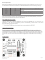
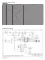
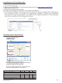
KS232D Time Recorder
www. av ea . cc
- log the date, time and card ID
- capture photo and email records
- late, tardy, overtime and total hours report
- with MSACCESS database
- export to plain text or EXCEL file
User manual : http://avea.cc/spec/ks232d.pdf
Time Recorder software : http://avea.cc/sw/TR.zip.
Setup info : http://avea.cc/setup/ks232d.html
INTRODUCTION
This is a low cost time recorder unit with RS232 interface to connect to PC directly. It comes
with a time recording software (for Windows) which logs the time and the card ID from the
reader unit into a database file (in MSACCESS format, located on the same directory of the
program). Also it can export the database to a plain text file and Excel file for data interchange
with other softwares.
A 9 to 12V DC supply is required to power the kit, which has a current consumption of less
than 200mA. A 9VDC/300mA (2.1mm center positive) plug pack will do fine. A DB9 female to
DB9 male straight through connecting cable is required to connect to PC.
OPERATION
There is a 6-position dip switch for configure the operation of the unit.
POSITION
6
5
DESCRIPTION
SPD0
SPD1
4
BEEP
3
MODE
2
1
FMT0
FMT1
SPD1
OFF
OFF
ON
ON
FMT1
OFF
OFF
FMT0
OFF
ON
ON
OFF
ON
ON
Re: KS232D\20110428
MADE IN CHINA
FUNCTION
Set the communication speed to host. The frame structure is
no parity, one start bit and one stop bit. There is no flow
control.
ON: to generate a beep sound on valid card reading.
OFF: no sound will be generated.
OFF: to keep sending the code to the host continuously.
ON: to send the code once.
To select the output format of the code.
SPD0
OFF
ON
OFF
ON
FUNCTION
1200 bit/s. (Setting for Time Recorder software)
9600 bit/s.
38400 Kbit/s.
115200 Kbit/s.
FUNCTION
Format 0, ASCII format: xxxxxxxxxxx<0x0a><0x0d> (i.e. 11 digit + LF + CR)
Format 1, ASCII format: xxx,xxxxx<0x0a><0x0d> (i.e. 3 digit + comma + 5
digit + LF + CR)
Format 2, ASCII format: xxxxx,xxxxxxxx<0x0a><0x0d> (i.e. 5 digit + comma +
8 digit + LF + CR)
Format 3, Reserved for the time attendance software
Page 1
Normal Operation
Basically the KS232D is the same as KS232 except for Format 3 operation. In order to use
the bundled time attendance software, the KS232D SHOULD have the following settings:
OPTION
SPD0
SPD1
BEEP
MODE
FMT0
FMT1
POSITION
OFF
OFF
OFF
ON
ON
ON
DESCRIPTION
Set 1200 bit/s communication speed (*** for Time
Recorder)
Disable the local beep sound generation
Send code once enabled
Select FORMAT 3, A MUST to get the software works
Other than Format 3 operation, all operations are the same as KS232 (MS232), interested
parties can download the manuals from the website.
SOFTWARE INSTALLATION
The KIT comes with a bundled CDROM. Just insert the CDROM into your computer (run
Windows), it will start the installation process automatically. Please refer to the Time
Recorder Startup Guide for details.
***** ALLOW ACCESS feature for electric lock is not available for KS232D.
CIRCUIT DESCRIPTION
The unit make use of an highly integrated module MS232D which is the heart of the unit
providing all the functionalities. By adding small amounts of surrounding components, the
complete proximity card reader unit is built. U1 is the regulator for the unit. U3 is used as the
level shifter in order to interface to the RS232 link. By writing simple application software on
the PC side, the unit can be used for attendance application, restricted access controlling,
etc.
PCB LAYOUT
Re: KS232D\20110428
MADE IN CHINA
Page 2
PART LIST (PCB Assembly)
ITEM
1
2
3
4
5
6
7
8
9
10
11
12
13
14
15
16
17
18
19
REFERENCE
U1
U2
U3
C1
C2, 3, 7, 9
C4, 10, 11-15
C5, 6
C8
D1
D3
D4
D2
R1, 2, 3, 4
R5
BZ1
J3
J6, L1
J9
PCB
COMPONENT
7805
MS232D with IC socket
MAX232 with IC socket
470uF 25V
Mono. Capacitor 0.1uF
E. Capacitor 10uF 25V
C. Capacitor 470pF
DIP Switch 6 Position
Rectifier 1N4001
Green LED
Red LED
Yellow LED
Resistor 390 ohm
Resistor 4.7 Kohm
5V Buzzer
2.1mm DC JACK
2-Pin Terminal Block
DB9 Female Connector
scm-ap-05a
REMARK
Regulator
Proximity card reader module
Level shifter
or 330uF 25V
or 10uF 50V
Not used.
Center terminal is positive.
L1 is used to connect the coil antenna.
Use straight through cable to connect to a PC.
SCHEMATIC DIAGRAM
Re: KS232D\20110428
MADE IN CHINA
Page 3
Installation of Time Recorder:
1. Turn on the computer.
2. Download and install the Time Recorder software from http://avea.cc/sw/TR.zip .
3. Save and unzip the file.
4. Execute the setup.exe program.
5. Follow the installation instruction to finish the installation.
3.The detailed installation manual for the Time Recorder will be automatically installed into
your computer when you install the application software. Follow the installation
instruction to finish the installation and follow the Installation Manual of Time Recorder
from Start for details of Time Recorder's Setup.
Time Recorder Quick Start
1. Setup the RFID Readers
2. EMAIL Settings
3. Webcam Setup
LIVE VIDEO
PHOTO
(from PC Camera)
(Card Information)
PICTURE
(Captured by PC Camera
while user presenting
the ID card to the reader)
4. Present the ID cards to the reader.
5. Double click the record to enter Card Information.
Or, Edit Card Information in Setup
6. Start and enjoy the Time Recorder.
For details, please check the Installation Manual or
email us at [email protected] for support.
INDICATION
Stand by mode – waiting for instruction
RED LED GREEN LED
BUZZER
LOCK
Blink
Action: Present a card to the reader
The reader is not connected to the computer
ON
ID card with NO Card Information
ON
ID card with Card Information
ON
ON
ON
ID card with Card Information and access allowed
ON
ON
ON
Re: KS232D\20110428
MADE IN CHINA
ON
RELEASE
Page 4