1
Artisan Technology Group is your source for quality
new and certified-used/pre-owned equipment
• FAST SHIPPING AND
DELIVERY
• TENS OF THOUSANDS OF
IN-STOCK ITEMS
• EQUIPMENT DEMOS
• HUNDREDS OF
MANUFACTURERS
SUPPORTED
• LEASING/MONTHLY
RENTALS
• ITAR CERTIFIED
SECURE ASSET SOLUTIONS
SERVICE CENTER REPAIRS
Experienced engineers and technicians on staff
at our full-service, in-house repair center
WE BUY USED EQUIPMENT
Sell your excess, underutilized, and idle used equipment
We also offer credit for buy-backs and trade-ins
www.artisantg.com/WeBuyEquipment
InstraView REMOTE INSPECTION
LOOKING FOR MORE INFORMATION?
Visit us on the web at www.artisantg.com for more
information on price quotations, drivers, technical
specifications, manuals, and documentation
SM
Remotely inspect equipment before purchasing with
our interactive website at www.instraview.com
Contact us: (888) 88-SOURCE | [email protected] | www.artisantg.com
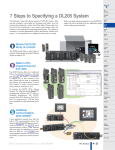
7 Steps to Specifying a DL205 System
PLC
7 STEPS TO SPECIFYING A DL205 SYSTEM
7 steps to help specify
a successful system
Before you begin selecting products for
your DL205 PLC system, be sure to evaluate all of your application needs and any
future growth potential.
The following 7 steps will help you specify a DL205 PLC system. They are also
covered in more detail on the pages that follow. Your first priority when designing a
system should be safety. Please make sure that all of the components in your system
will operate within the product’s environmental and operating specifications. This
desk reference is intended to provide abbreviated product descriptions, benefits and
prices. It is not intended to be a substitute for the product manuals.
Review the DL205
family of products
The DL205 family offers a wide variety of
products. Please review the product
offering starting on page 4–23.
Select a CPU,
programming tool
and cable
The DL205 family offers four CPUs: the
D2-260, D2-250-1, D2-240 and
D2-230. The WinPLC, a Windows®
CE-based CPU, is also covered in this
step. Please take the time to understand
the features and specifications of each
CPU model (i.e. built-in communications ports protocols, instructions, etc.).
To program the DL205 CPUs, choose
between
the
Windows-based
DirectSOFT32 programming software
and PC cable or handheld programmer.
The WinPLC requires Think & Do
Studio or Think & Do Live! for
programming. CPU-slot slave base
controllers are also introduced in this
step.
Additional
communications
ports needed?
If your application requires more than the
built-in CPU communications ports, then
select the H2-ECOM Ethernet
Communications Module or the D2DCM Serial Communications Module.
These modules add more ports for
networking or connection to an HMI, etc.
The H2-SERIO serial communications
module can be used with the WinPLC to
add more communications ports.
w w w. a u to m at i o n d i re c t . c o m / d l 205
PLC Products
Artisan Technology Group - Quality Instrumentation ... Guaranteed | (888) 88-SOURCE | www.artisantg.com
4–21
7 Steps to Specifying a DL205 System
7 STEPS TO SPECIFYING A DL205 SYSTEM
Select the
discrete, analog
and specialty
I/O modules
Since there are several different types of
I/O and speciality modules available for
the DL205 system, it is important to
review the module specifications in detail
when selecting them for your system.
The hardware specifications for the
modules are described at the end of this
DL205 section, starting with the
speciality modules and followed by the
discrete and analog I/O modules.
Choose an I/O
configuration
method
The DL205 offers several configurations
of I/O. Choose among local I/O, local
expansion I/O and remote I/O. A
DL205 system can be developed using a
combination of the configuration
arrangements. It is important to understand the octal addressing scheme and
I/O module placement restrictions that
are described in this step.
Example: nsion I/O
Local expa
Check the
power budget
It is very important to verify that the
selected CPU and I/O modules will
operate within the base power budget.
Tables list the power supplied and
consumed by each DL205 device. This
step also describes base dimensions and
mounting requirements.
Place your
order!
Place your order either online at
www.automationdirect.com, by calling
1-800-633-0405 or by faxing your order
to 1-770-889-7876. See the Ordering
section in this desk reference for details.
4–22
PLC Products
1 - 80 0 - 633 - 0405
Artisan Technology Group - Quality Instrumentation ... Guaranteed | (888) 88-SOURCE | www.artisantg.com
DL205 Product Family
PLC
HERE
STEP 1: REVIEW THE DL205 PRODUCT FAMILY
CPUs
D2-260 – 30.4K words total memory
2 communications ports
16 built-in PID loops with auto-tuning
D2-250-1 – (Replaces D2-250)
14.8K words total memory
2 communications ports
4 built-in PID loops with auto-tuning
D2-240 – 3.8K total memory,
2 communications ports
D2-230 – 2.4K total memory
1 communications port
Windows CE CPUs
WinPLC (H2-WPLC*-**)
Programming tools
DirectSOFT32 Programming Software for
Windows (PC-PGMSW or PC-PGM-205)
Handheld Programmer (D2-HPP)
Bases
3-slot base (includes power supply)
110/220 VAC (D2-03B-1)
12/24 VDC (D2-03BDC1-1)
4-slot base (includes power supply)
110/220 VAC (D2-04B-1)
12/24 VDC (D2-04BDC1-1)
6-slot base (includes power supply)
110/220 VAC (D2-06B-1)
12/24 VDC (D2-06BDC1-1)
125 VDC (D2-06BDC2-1)
9-slot base (includes power supply)
110/220 VAC (D2-09B-1)
12/24 VDC (D2-09BDC1-1)
125 VDC (D2-09BDC2-1)
Local expansion
modules
(D2-250-1 or D2-260 using D2-0*B-1 or
D2-0*BDC*-1 only)
Base expansion module
(D2-EM)
Expansion base controller module
(D2-CM)
Expansion base cable (D2-EXCBL-1)
Discrete
input modules
DC input
8-pt. 12-24 VDC sink/source
(D2-08ND3)
16-pt. 24 VDC sink/source
(D2-16ND3)
32-pt. 24VDC sink/source
(D2-32ND3)
32-pt. 5-12VDC sink/source
(D2-32ND3-2)
Discrete input modules (continued)
AC input
8-pt. 110 VAC (D2-08NA-1)
16-pt. 110 VAC (D2-16NA)
8-pt. 220 VAC (D2-08NA-2)
Discrete
output modules
DC output
4-pt. 12-24 VDC sink (D2-04TD1)
8-pt. 12-24 VDC sink (D2-08TD1)
8-pt. 12-24 VDC source (D2-08TD2)
16-pt. 12-24 VDC sink (D2-16TD1-2)
16-pt. 12-24 VDC source (D2-16TD2-2)
32-pt. 12-24 VDC sink (D2-32TD1)
32-pt. 12-24 VDC source (D2-32TD2)
AC output
8-pt. 18-220 VAC (D2-08TA)
8-pt. 20-125 VAC (F2-08TA)
12-pt. 18-110 VAC (D2-12TA)
Relay output
4-pt. 4A/pt (Isolated) (D2-04TRS)
8-pt. 1A/pt (D2-08TR)
8-pt. 10A/pt. (F2-08TR)
8-pt. 7A/pt (Isolated) (F2-08TRS)
12-pt. 1.5A/pt (D2-12TR)
Combination
discrete modules
4-pt. 24 VDC in/4pt Relay Out (D2-08CDR)
Analog modules
Analog input
4-ch. in, 12 bit, current (F2-04AD-1)
4-ch. in, 12 bit, voltage (F2-04AD-2)
8-ch. in, 12 bit, current (F2-08AD-1)
8-ch. in, 12 bit, voltage (F2-08AD-2)
Analog output
2-ch. out, 12 bit, current (F2-02DA-1)
2-ch. out, 16 bit, current (Isolated)
(F2-02DAS-1)
2-ch. out, 12 bit, voltage (F2-02DA-2)
2 -ch. out, 16 bit, voltage (Isolated)
(F2-02DAS-2)
8-ch. out, 12 bit, current (F2-08DA-1)
8-ch. out, 12 bit, voltage (F2-08DA-2)
Combination analog in/out
4-ch. in/2-ch. out, 12 bit, current
(F2-4AD2DA)
8-ch. in/4-ch. out, 16 bit, current
(F2-8AD4DA-1)
8-ch. in/4-ch. out, 16 bit, voltage
(F2-8AD4DA-2)
Temperature input
4-ch. in, RTD (F2-04RTD)
4-ch. in, Thermocouple (F2-04THM)
w w w. a u to m at i o n d i re c t . c o m / d l 205
Communications/
networking modules
Ethernet Communications Module
(H2-ECOM (-F)
(H2-ECOM 100)
Data Communications Module
(D2-DCM)
Remote I/O modules
Ethernet
Ethernet Remote Master Module
(H2-ERM(-F))
Ethernet Base Controller (slave)
(H2-EBC(-F))
(H2-EBC 100)
Serial
Remote Master Module (D2-RMSM)
Remote Slave Module (D2-RSSS)
Specialty modules
Basic CoProcessor (F2-CP128)
8-pt Input Simulator (F2-08SIM)
Counter I/O (H2-CTRIO)
Counter Interface (D2-CTRINT)
CPU-slot
slave controllers
Ethernet Base Controller (H2-EBC)
DeviceNet Slave (F2-DEVNETS-1)
Profibus Slave (H2-PBC)
SDS Slave (F2-SDS-1)
Operator interface
See the Operator Interface section in this
desk reference for a complete line of compatible text and touch panels and configuration software.
Connection systems
See the Connection Systems section in this
desk reference for information on
DINnector terminal blocks, ZIPLink connection systems and other connection
accessories for use with the DL205 system.
PLC Products
Artisan Technology Group - Quality Instrumentation ... Guaranteed | (888) 88-SOURCE | www.artisantg.com
4–23
DL205 CPU Specifications
HERE
STEP 2: SELECT THE CPU, PROGRAMMER AND CABLE
There are many things to consider when
choosing a CPU, most of which depend
on your particular application. The
facing page provides a comparison
between the CPUs. This section provides
a quick summary of the key features for
each CPU.
System capacity
System capacity is the ability of the CPU
to accommodate a variety of applications. Consider both ladder memory and
data registers (V-memory). For ladder
memory, most Bodean instructions
require one word. Some other instructions, such as timers, counters, etc.
require two or more words.
Our V-memory locations are 16-bit
words and are useful for data storage, etc.
If you think you may exceed 256 local
I/O points, then select the D2-250-1 or
the D2-260 CPU which support local
expansion of up to two or four additional
bases, respectively.
The D2-240, D2-250-1 and D2-260
support the Ethernet and standard
Remote Master module that are used to
build a remote I/O network. Port 2 on
the D2-250-1 and D2-260 can also serve
as a remote I/O master.
Performance
If you are using basic Bodean instructions and speed is not the primary
concern, then the D2-230 or D2-240
will do the job. For applications that
require fast scan times, additional
communications or advanced instructions, choose the D2-250-1 or D2-260
CPU. The D2-260 is our fastest CPU for
performing even the most basic of math
or data instructions, and will provide
better overall performance than the other
DL205 CPUs.
Programming
and diagnostics
Our CPUs offer an incredible array of
instructions and diagnostic features that
can save you many hours of programming and debug time. From basic
Bodean contact logic to PID and floating
point math, we have it covered! The table
on the next page covers some of the basic
instruction categories, but for more
details, see our complete list of instructions at the end of this section. If you
already have DirectSOFT32 and/or a
Handheld Programmer, you may have to
upgrade the software/firmware to accommodate the D2-260.
Built-in CPU
communications
Every DL205 CPU provides at least one
built-in RS232 communication port. If
you’re using an operator interface, then
you should choose the D2-240, D2-2501 or D2-260 CPU. The D2-240, D2250-1 and D2-260 CPUs offer two
built-in communication ports. The D2240 supports our DirectNET™ slave
protocol on the bottom port, which
provides a quick and easy network
connection to any DirectNET master. If
you need the most flexibility possible,
then consider the D2-250-1 or D2-260
CPU. These CPUs offer built-in
DirectNET slave support capability on
the top and bottom ports, and
DirectNet/MODBUS RTU master/slave
support on the bottom. The bottom port
supports baud rates up to 38.4K baud.
The D2-260 provides support for ASCII
IN/OUT communications.
If you require more than two ports, we
also offer an Ethernet Communications
Module that can be used to quickly add a
communication port to a DL205 system
with a D2-240, D2-250-1 or D2-260
CPU. The D2-DCM module can also be
added to these CPUs to provide an additional serial communications port.
The WinPLC brings PLC and PC
technologies together by providing a
Windows CE operating system environment for the DL205 hardware.
See the WinPLC pages later in this
section for details on the WinPLC.
H2-WPLC*-**
4–24
PLC Products
D2-260
D2-250-1
D2-240
D2-230
1 - 80 0 - 633 - 0405
Artisan Technology Group - Quality Instrumentation ... Guaranteed | (888) 88-SOURCE | www.artisantg.com
DL205 CPU Specifications
PLC
HERE
DL205 CPU SPECIFICATIONS
DL205 CPU Comparison
System Capacity
D2-230
D2-240
D2-250-1
D2-260
Total memory available (words)
Ladder memory (words)
V-memory (words)
Battery backup
Total CPU memory I/O pts. available (actual I/O pts.
2.4K
2048 EEPROM
256
Yes
256
3.8K
2560 EEPROM
1024
Yes
896
14.8K
7680 Flash
7168
Yes
2048
30.4
15872 Flash
14592
Yes
8192 (1024 X + 1024 Y +
depend on I/O configuration method selected)
(320 X + 320 Y + 256 CR)
Local I/O (pts.)
Local Expansion I/O (pts.)
256
none
256
none
Serial Remote I/O (pts.)
N/A
Remote I/O channels
I/O per remote channel
Ethernet Remote I/O
Discrete I/O pts.
N/A
N/A
N/A
N/A
Analog I/O channels
Remote I/O channels
I/O per remote channel
N/A
N/A
N/A
896 max.
(Including local I/O)
2
2048 (limited to 896)
Yes
896 max.
(Including local I/O)
Map into V-memory
(512 X + 512 Y + 1024 CR)
2048 CR + 2048 GX + 2048 GY)
256
768 (2 exp. bases max)
(Including local I/O)
2048 max.
(Including local and exp.I/O)
8 (7+1 CPU port)
2048
Yes
2048 max.
(Including local and exp.I/O)
Map into V-memory
256
1280 (4 exp. bases max.)
(Including local I/O)
8192 max.
(Including local & exp. I/O)
8 (7+1 CPU port)
2048
Yes
8192
(Including local and exp.I/O)
Map into V-memory
Limited by power budget
16,384 (limited to 896)
Limited by power budget
16,384 (16 fully expanded
H4-EBC slaves using V-memory
and bit-of-word instructions)
H4-EBC slaves using V-memory
and bit-of-word instructions)
3.3µs
4-6ms
1.4µs
10-12ms
0.61µs
1.9ms
0.61µs
1.9ms
Yes
Yes/256
Yes
Variable
113
256
64
64
Yes
No
No
No
Yes
No
No
No
No
No
No
No
No
Yes
Yes
No
Yes
Yes/512
Yes
Variable
129
256
128
128
Yes
Yes
Yes
Yes
Yes
No
No
No
No
No
No
No
Yes
Yes
Multi-level
No
Yes
Yes/1024
Yes
Variable
174
1024
256
128
Yes
Yes
Yes
Yes
Yes
Yes
No
No
Yes, 4 loops
Yes
Yes
Yes
Yes
Yes
Multi-level
Yes
Yes
Yes/1024
Yes
Variable
231
2048
256
256
Yes
Yes
Yes
Yes
Yes
Yes
Yes
Yes
Yes, 16 loops
Yes
Yes
Yes
Yes
Yes
Multi-level
Yes
Port 1 RS-232C
Port 1 RS-232C and
Port 2 RS-232C
Yes
Yes
No
No
19.2K port 2
Port 1 RS-232C and
Port 2 RS (232C/422)
Yes
Yes
Yes
OUT
38.4K port 2
Port 1 RS-232C and
Port 2 RS (232C/422/485)
Yes
Yes
Yes
IN/OUT
38.4K port 2
Limited by power budget
16,384 (16 fully expanded
Performance
Contact execution (Bodean)
Typical scan (1K Bodean)
Programming and Diagnostics
RLL Ladder Style
RLLPLUS/Flowchart Style (Stages)
Run time editing
Variable/fixed scan
Instructions
Control relays
Timers
Counters
Immediate I/O
Subroutines
For/Next loops
Timed Interrupt
Integer Math
Floating-point Math
Trigonometric functions
Table Instructions
PID
Drum Sequencers
Bit of Word
ASCII Print
Real-time clock/calender
Internal diagnostics
Password security
System and user error log
Communications
Built-in ports
K-sequence (proprietary protocol)
DirectNET™
MODBUS RTU master/slave
ASCII communications
Maximum baud rate
Yes
No
No
No
9600
w w w. a u to m at i o n d i re c t . c o m / d l 205
PLC Products
Artisan Technology Group - Quality Instrumentation ... Guaranteed | (888) 88-SOURCE | www.artisantg.com
4–25
DL205 CPU Specifications
HERE
D2-260 KEY FEATURES
Easily connect programming devices or HMI to CPU ports
D2-260 can serve as network master
DL260 CPU
D2-260
<--->
0
MODBUS® RTU or DirectNET™ network protocol
Use port 2 on D2-260 or
D2-250-1 to network slaves
Connect operator interfaces to port 1 on the slaves
Use D2-DCM module if D2-240
is slave or if D2-250-1/D2-260
port 2 is occupied
Powerful built-in
CPU communications
16 PID loops
with auto-tuning
Our D2-260 CPU provides all the capabilities of the other DL205 CPUs (as well
as our D4-450 CPU), plus several additional features rarely found in a PLC of
this size. With such an incredible array of
features, you may be able to replace PLCs
costing hundreds (or thousands) more.
Release
4.0
or
higher
of
DirectSOFT32™ is required to program
the D2-260. If you’re using a handheld
programmer, version 2.10 of the handheld programmer firmware is required.
Here are a few key features about the
D2-260 CPU:
The D2-260 offers two communications
ports that provide a vast array of
communication possibilities. The top
RJ-12 RS-232C port can be used for
programming, connection to an
EZText/EZTouch or DV-1000 operator
interface panel, or as a single K-sequence
or DirectNET slave. The 15-pin bottom
port (port 2) supports RS232C or
RS422/RS485. This port offers several
different protocol options such as:
Local expansion I/O
Port 2 can also serve as a remote I/O
master. The D2-260 supports the
Ethernet Communication module and
Data Communication Module for additional communications ports.
The D2-260 CPU can process up to 16
PID loops directly in the CPU. You can
select from various control modes
including automatic, manual, and
cascade. There are also a wide variety of
alarms including Process Variable, Rate
of Change, and Deviation. The loop
operation parameters (Process Variable,
Setpoint, Setpoint Limits, etc.) are stored
in V-memory, which allows easy access
from operator interfaces or HMIs. Setup
is accomplished with easy-to-use setup
menus and monitoring views in
DirectSOFT32 programming.
The auto-tuning feature is easy to use
and can reduce setup and maintenance
time. Basically, the CPU uses the autotuning feature to automatically determine near optimum loop settings. See
the D2-250-1 CPU section for a PID
loop control block diagram.
D2-260: Our most
powerful DL205 CPU
The D2-260 supports local expansion up
to five total bases (one CPU base and four
expansion bases). Expansion bases are
commonly used when there are not
enough slots available in the CPU base,
when the base power budget will be
exceeded, or when placing an I/O base at
a location away from the CPU base ( but
within the expansion cable limits). All
local and expansion I/O points are
updated on every CPU scan. Each local
expansion base requires the D2-CM
module in the CPU slot. The local CPU
base requires the D2-EM Expansion
Module, as well as each expansion base.
For more information on local expansion, refer to the Expansion Modules
pages later in this section.
4–26
PLC Products
• K-sequence
• DirectNET Master/Slave
• MODBUS RTU Master/Slave
• ASCII In/Out Communications
D2-260 local expansion system
Note: All bases in the system must be (-1) bases.
D2-EXCBL-1
(Category 5
straight-through
cable with RJ45
connectors)
D2-EM
D2-260
D2-EM
D2-CM
D2-EM
D2-CM
The D2-260 offers:
• Up to 4 expansion bases
• Up to 1024 inputs and 1024 outputs
• Up to 30m (98ft.) total expansion system cable
1 - 80 0 - 633 - 0405
Artisan Technology Group - Quality Instrumentation ... Guaranteed | (888) 88-SOURCE | www.artisantg.com
DL205 CPU Specifications
PLC
HERE
D2-260 KEY FEATURES
Full array of
instructions
Examples of MRS and MWX
instructions in DirectSOFT 4.0
The right instruction can greatly
simplify your programming task and can
save hours of programming time.
The D2-260 supports over 225 powerful
instructions, such as:
• Four types of drum sequencers
• Leading / trailing edge triggered oneshots
• Bit of word manipulation
• Floating point conversions
• Trigonometric functions
• Table instructions
• ASCII IN/OUT instructions
For a complete list of instructions
supported by all DL205 CPUs, see the
end of this section.
1
2
3
4
5
6
11
15
10
The D2-260 CPU supports new easy-touse MODBUS Read/Write instructions
that expand our existing MODBUS
network instruction capabilities. The
MRX or MWX instructions allow you
to enter native Modbus addressing in
your ladder program with no need to
perform octal-to-decimal conversion.
We added Function codes 05, 06 and
the ability to read Slave Exception
Codes. These flexible instructions allow
the user to select the following parameters within one instruction window:
• 584/984 or 484 MODBUS data type
• Slave node (0-247)
• Function code
• MODBUS starting master / slave memory
address
• Number of bits
• Exception code starting address
RUN
Puts CPU into RUN mode
Allows peripherals (HPP, DirectSOFT32)
to select the mode of operation
Forces CPU out of RUN mode
TERM
STOP
Port 1
Protocols
Port 2 Pinouts
Pin Signal Definition
6
5
New MODBUS RTU
instructions
CPU is in RUN mode
CPU is in PROGRAM mode
Battery backup voltage is low
Battery backup voltage is OK or disabled
CPU internal diagnostics detects error
CPU is OK
CPU power good
CPU power failure
Mode Switch
Port1 Pinouts
Pin
Signal Definition
1
0V
2
5V
3
RS232C RXD
4
RS232C TXD
5
5V
6
0V
1
CPU Status Indicators
ON
OFF
ON
BATT
OFF
ON
CPU
OFF
ON
PWR
OFF
RUN
1
2
3
4
5
6
7
8
9
10
11
12
13
14
15
5VDC
TXD2 (RS232C)
RXD2 (RS232C)
RTS2 (RS232C)
CTS2 (RS232C)
RXD2- (RS422/485))
0VDC
0VDC
TXD2+ (RS422/485)
TXD2- (RS422/485)
RTS2+ (RS422/485)
RTS2- (RS422/485)
RXD2+ (RS422/485)
CTS2+ (RS422/485)
CTS2- (RS422/485)
Devices
Specs.
K-sequence slave, DirectNET™ slave,
MODBUS RTU slave
Can connect w/HPP, DirectSOFT32,
EZText/EZTouch, DV-1000, O/I panels, or
any DirectNET master
6P6C phone jack connector RS232C
9,600 baud
Fixed address
Odd parity only
8 data bits one start, one stop
asynchronous, half-duplex, DTE
Port 2
Protocols
Devices
Specs.
K-sequence slave, DirectNET
Master/Slave, MODBUS RTU
Master/Slave, ASCII IN/OUT,
Remote I/O Master
Can connect w/many devices, such as
PCs running DirectSOFT32, DSData, HMI
packages, EZText/EZTouch panels,
DV-1000, other O/I panels, any DirectNET
or MODBUS RTU master or slave, or
ASCII devices
HD15 connector
RS232C/RS422/485*
300/600/1200/2400/4800
9600/19.2K/38.4K baud
Odd, even, or no parity
Selectable address
(1-90, HEX 1 – 5A)
8 data bits, one start, one stop
Asynchronous,
Half-duplex, DTE
Battery (Optional)
D2-BAT-1
DN-15TB
ZIPLink
communications
adapter modules
ZIPLink cables and communications
adapter modules offer fast and convenient screw terminal connections for the
D2-260 bottom port. They are
RS232/422 DIP switch selectable. See
the Connection Systems section in this
desk reference for part numbers and
descriptions.
w w w. a u to m at i o n d i re c t . c o m / d l 205
Coin type, 3.0V Lithium battery, 560mA,
battery number CR2354
Note: Batteries are not needed for program backup. However, you
should order a battery if you have parameters in V-memory that must be
maintained in case of a power outage.
*RS485 for MODBUS protocol only
On-board memory
The D2-260 has 15.5K words of flash
memory on board for your program plus
14.2K words of data registers. With flash
memory, you don’t have to worry about
losing the program due to a bad battery.
Built-in remote
I/O connection
The bottom port on the D2-260 can be
used as a master for serial remote I/O
networks (see the D2-RSSS later in this
section for details).
PLC Products
Artisan Technology Group - Quality Instrumentation ... Guaranteed | (888) 88-SOURCE | www.artisantg.com
4–27
DL205 CPU Specifications
HERE
D2-260 KEY FEATURES
ASCII
communications
instructions
The D2-260 CPU supports several
easy-to-use instructions that allow ASCII
strings to be read into and written from
the PLC communications ports.
Raw ASCII: Port 2 can be used for either
reading or writing raw ASCII strings,
but not for both.
Embedded ASCII characters: The D2260 can decipher ASCII embedded
within a supported protocol (KSequence,
DirectNet,
Modbus,
Ethernet) via the CPU ports, H2ECOM or D2-DCM.
Here's how the D2-260 can
receive ASCII input strings:
1. ASCII IN (AIN) - This instruction
configures port 2 for raw ASCII input
strings with parameters such as fixed
and variable length ASCII strings,
termination characters, byte swapping
options, and instruction control bits.
Use barcode scanners, weight scales,
etc. to write raw ASCII input strings
into port 2 based on the (AIN)
instruction’s parameters.
2. Write embedded ASCII strings
directly to V-memory from an
external HMI or similar master
device via a supported communications protocol using the CPU ports,
H2-ECOM or D2-DCM. The AIN
instruction is not used in this case.
3. If a D2-260 PLC is a master on a
network, the Network Read instruction (RX) can be used to read
embedded ASCII data from a slave
device via a supported communications protocol using port 2, H2ECOM or D2-DCM. The RX
instruction places the data directly
into V-memory.
4–28
PLC Products
Here's how the D2-260 can
write ASCII output strings:
1. Print from V-memory (PRINTV) Use this instruction to write raw
ASCII strings out of port 2 to a
display panel or a serial printer, etc.
The instruction features the starting
V-memory address, string length, byte
swapping options, etc. When the
instruction's permissive bit is enabled,
the string is written to port 2.
2. Print to V-memory (VPRINT) - Use
this instruction to create pre-coded
ASCII strings in the PLC (i.e. alarm
messages). When the instruction's
permissive bit is enabled, the message
is loaded into a pre-defined Vmemory address location. Then the
(PRINTV) instruction may be used
to write the pre-coded ASCII string
out of port 2. American, European
and Asian Time/Date stamps are
supported.
3. Print Message (PRINT) - This
existing instruction can be used to
create pre-coded ASCII strings in the
PLC. When the instruction's permissive bit is enabled, the string is written
to port 2. The VPRINT/PRINTV
instruction combination is more
powerful and flexible than the PRINT
instruction.
4. If a D2-260 PLC is a master on a
network, the Network Write instruction (WX) can be used to write
embedded ASCII data to an HMI or
slave device directly from V-memory
via a supported communications
protocol using port 2, H2-ECOM or
D2-DCM.
Additional new instructions
that help manage the ASCII
strings
The following instructions can be very
helpful in managing the ASCII strings
within the CPU’s V-memory:
ASCII Find (AFIND) - Finds where a
specific portion of the ASCII string is
located in continuous V-memory
addresses. Forward and reverse searches
are supported.
ASCII Extract (AEX) - Extracts a
specific portion (usually some data
value) from the ASCII find location or
other known ASCII data location.
Compare V-memory (CMPV) - This
instruction is used to compare two
blocks of V-memory addresses and is
usually used to detect a change in an
ASCII string. Compared data types must
be of the same format (i.e. BCD, ASCII,
etc.).
Swap Bytes (SWAPB) - Usually used to
swap V-memory bytes on ASCII data
that was written directly to V-memory
from an external HMI or similar master
device via a communications protocol.
The AIN and AEX instructions have a
built-in byte swap feature.
Examples of AIN and VPRINT
instructions in DirectSOFT 4.0
1 - 80 0 - 633 - 0405
Artisan Technology Group - Quality Instrumentation ... Guaranteed | (888) 88-SOURCE | www.artisantg.com
DL205 CPU Specifications
PLC
HERE
D2-250-1 KEY FEATURES
Easily connect programming devices or HMI to CPU ports
D2-250-1 can serve as network master
DL250-1 CPU
D2-250-1
<--->
0
MODBUS® RTU or DirectNET™ protocol
Use port 2 on D2-260 or
D2-250-1 to network slaves
Connect operator interfaces to port 1 on the slaves
D2-250-1 replaces
D2-250
Our D2-250-1 CPU replaces the D2250 CPU. The D2-250-1 offers all the
features and functionality of the D2-250
with the addition of local I/O expansion
capability. The D2-250-1 offers an
incredible array of features for a CPU
that costs so little.
Release 2.1 or higher of DirectSOFT™ is
required to program the D2-250-1.
Release 4.0 is required if you intend to
use local expansion I/O. If you’re using a
handheld programmer, version 2.10 of
the handheld programmer firmware is
required. A few key features of the D2250-1 CPU follow.
Local expansion I/O
The D2-250-1 supports local expansion
up to three total bases (one CPU base and
two expansion bases). Expansion bases are
commonly used when there are not
enough slots available in the CPU base,
when the base power budget will be
exceeded or when placing an I/O base at a
location away from the CPU base, but
within the expansion cable limits. All local
and expansion I/O points are updated on
every CPU scan. Each local expansion
base requires the D2-CM module in the
CPU slot. The local CPU base requires
the D2-EM Expansion Module, as well
as each expansion base. For more information on local expansion, refer to the
Expansion Modules pages later in this
section.
Powerful built-in
CPU communications
Four PID
loops with
auto-tuning
The D2-250-1 offers two communication ports that provide a vast array of
communication possibilities. The top
RS232C port is for programming,
connection to an EZText/EZTouch
operator interface panel or DV-1000, or
to serve as a single DirectNET slave. The
15-pin bottom port (port 2) supports
RS232C or RS422. This port offers
several different protocol options such
as:
• K-sequence
• DirectNET master/slave
• MODBUS RTU master/slave
Port 2 can also serve as a remote I/O
master. The D2-250 supports the
Ethernet Communication Module and
Data Communication Module for additional communications ports.
D2-250-1 local expansion system
Note: All bases in the system must be (-1) bases.
D2-CM
Use D2-DCM module if D2-240
is slave or if D2-250-1/D2-260
port 2 is occupied
The D2-250-1 CPU can process up to 4
PID loops directly in the CPU. You can
select from various control modes
including automatic, manual, and
cascade control. There are a wide variety
of alarms including Process Variable,
Rate of Change, and Deviation. The
loop operation parameters (Process
Variable, Setpoint, Setpoint Limits, etc.)
are stored in V-memory, which allows
easy access from operator interfaces or
HMIs. Setup is accomplished with easyto-use setup menus and monitoring
views in DirectSOFT32 programming.
The auto-tuning feature is easy to use
and can reduce setup and maintenance
time. Basically, the CPU uses the autotuning feature to automatically determine near optimum loop settings. See
the next page for a PID loop control
block diagram.
The D2-250-1 offers:
• up to 2 expansion bases
• up to 768 physical I/O points
D2-EM
• up to 30m (98ft.) total expansion system cable
D2-EM
D2-CM
D2-EM
D2-250-1
CPU
w w w. a u to m at i o n d i re c t . c o m / d l 205
D2-EXCBL-1 (Category 5
straight-through cable with
RJ45 connectors)
PLC Products
Artisan Technology Group - Quality Instrumentation ... Guaranteed | (888) 88-SOURCE | www.artisantg.com
4–29
DL205 CPU Specifications
HERE
D2-250-1 KEY FEATURES
CPU Status Indicators
Full array of
instructions
The D2-250-1 supports over 160
powerful instructions, such as:
• Four types of drum sequencers
• Leading and trailing edge triggered oneshots
• Bit of word manipulation
• Floating point conversions
• 4 PID loops
For a complete list of instructions
supported by all DL205 CPUs, see the
end of this section.
1
2
3
4
5
6
CPU is in RUN mode
CPU is in PROGRAM mode
Battery backup voltage is low
Battery backup voltage is OK or disabled
CPU internal diagnostics detects error
CPU is OK
CPU power good
CPU power failure
RUN
Puts CPU into RUN mode
Allows peripherals (HPP, DirectSOFT32)
to select the mode of operation
Forces CPU out of RUN mode
Mode Switch
TERM
P ort 1 P inouts
Pi n
S igna l D e finition
1
2
3
4
5
6
STOP
0V
5V
R S 232C D a ta in
R S 232C D a ta out
5V
0V
Port 1
Protocols
On-board memory
The D2-250-1 has 7.6K words of flash
memory on board for your program plus
7.1K words of V-memory (data registers).
With flash memory, you don’t have to
worry about losing the program due to a
bad battery. If you have critical data
stored in the capacitor backed Vmemory, simply purchase the optional
lithium battery (D2-BAT-1) to permanently maintain these parameters.
ON
OFF
ON
BATT
OFF
ON
CPU
OFF
ON
PWR
OFF
RUN
Devices
Port 2 Pinouts
Pin
Signal Definition
6
1
11
15
5
10
1
2
3
4
5
6
7
8
9
10
11
12
13
14
15
5VDC
TXD2 (RS232C)
RXD2 (RS232C)
RTS2 (RS232C)
CTS2 (RS232C)
RXD2- (RS422)
0VDC
0VDC
TXD2+ (RS422)
TXD2- (RS422)
RTS2+ (RS422)
RTS2- (RS422)
RXD2+ (RS422)
CTS2+ (RS422)
CTS2- (RS422)
Specs.
Port 2
Protocols
Devices
Built-in remote
I/O connection
In addition to providing outstanding
communications capabilities, the bottom
port on the D2-250-1 can also be a
master for remote I/O networks. If you
need extra I/O at a remote distance from
the CPU, you can use this port to add up
to seven of our remote slave stations.
(See the D2-RSSS for additional information. later in this section).
Specs.
ZIPLink cables and communications
adapter modules offer fast and convenient screw terminal connections for the
D2-250-1 lower port. They are
RS232/422 DIP switch selectable. For
part numbers and descriptions, see the
Connection Systems section in this desk
reference .
4–30
PLC Products
K-sequence slave, DirectNET
Master/Slave, MODBUS RTU
Master/Slave, ASCII OUT,
Remote I/O Master
Can connect w/many devices, such as
PCs running DirectSOFT32, DSData, HMI
packages, EZText/EZTouch panels,
DV-1000, other O/I panels, any DirectNET
or MODBUS RTU master or slave, or
ASCII devices
HD15 connector
RS232C/RS422
300/600/1200/2400/4800
9600/19.2K/38.4K baud
Odd, even, or no parity
Selectable address
(1-90, HEX 1 – 5A)
8 data bits, one start, one stop
Asynchronous,
Half-duplex, DTE
Battery (Optional)
Coin type, 3.0V Lithium battery, 560mA,
battery number CR2354
Note: Batteries are not needed for program backup. However, you should order a battery if you
have parameters in V-memory that must be maintained in case of a power outage.
D2-BAT-1
DN-15TB
ZIPLink
communications
adapter modules
K-sequence slave, DirectNET™ slave,
MODBUS RTU slave
Can connect w/HPP, DirectSOFT32,
EZText/EZTouch, DV-1000, O/I panels, or
any DirectNET master
6P6C phone jack connector RS232C
9,600 baud
Fixed address
Odd parity only
8 data bits one start, one stop
asynchronous, half-duplex, DTE
EZText/EZTouch,
DV–1000, or other
OI Units
DL205 analog output or
discrete output module
Setpoint
Value
Control
Equation
Control
Output
Control
Element
Proces s
(heater , etc.)
(valve, etc.)
DL205 Analog or
Temperature
Input Modules
PID loop control block diagram
Proces s
Variable
Sensor
Proces s
Variable
Input
1 - 80 0 - 633 - 0405
Artisan Technology Group - Quality Instrumentation ... Guaranteed | (888) 88-SOURCE | www.artisantg.com
DL205 CPU Specifications
PLC
HERE
D2-230/240 KEY FEATURES
DL240 CPU
D2-240
<--->
D2-240: our best
value DL205 CPU
The D2-240 provides a subset of the D2250-1’s capabilities. If you need a good
CPU with multiple communications
ports, and complex math or PID isn’t
required, then the D2-240 is the CPU
for you!
Built-in memory
There is 2.5K of EEPROM program
memory in the D2-240. No additional
memory is required.
If you have critical data stored in the
capacitor backed V-memory, simply
purchase the optional lithium battery
(D2-BAT) to permanently maintain
these parameters as well.
programmer, EZTouch/EZText panels,
or to the DV-1000. The bottom port is a
slave-only port and supports our
DirectNET™ or K-sequence protocol at
speeds up to 19.2K baud. If you’re using
an operator interface or if you plan on
connecting the system to a network later
on, then you can choose the D2-240.
The D2-240 also supports the D2-DCM
Data Communication Module and the
H2-ECOM Ethernet Communication
Modules.
DL205 spare
EEPROM chips
There may be cases where you want to
have a spare EEPROM chip available.
For example, maybe you need to upgrade
a customer’s machine with your latest
enhancements. You can purchase extra
EEPROM chips (two per pack). These
can be installed in the CPU (D2230/D2-240 only) and programmed, or
they can be programmed directly with
the DL205 handheld programmer.
CPU Side View
Write Protect
Jumper
E E PROM
Powerful instructions
The D2-240 instructions cover most of
the capability of our more powerful D2250-1 and allow you to cover a wide
variety of applications. Instructions
include Bodean logic, data manipulation, integer math, interrupts, subroutines, FOR/NEXT loops, etc. For a
complete list of instructions, see the back
of this section.
Two built-in RS232C
communications ports
EEPROM location
D2-EE-1
CPU
D2-230
D2-EE-2
D2-240
CPU Program
2.0K
Storage Capacity
2.4K
Writing Cycle
Life
10,000
10,000
Write Inhibit
CPU jumper
CPU jumper
Memory Clear
Method
Electrical
Electrical
The D2-240 offers two communication
ports. The top port can be used for a
direct connection to a personal computer
for programming, to our handheld
w w w. a u to m at i o n d i re c t . c o m / d l 205
DL230 CPU
D2-230
<--->
D2-230: our lowest
price DL205 CPU
The D2-230 is our most economical
CPU in the DL205 product family. If
you are looking at the DL205 primarily
because of the size or for other reasons
that don’t require lots of CPU horsepower, then give the D2-230 a try.
Built-in
EEPROM memory
There is 2.0K of EEPROM program
memory in the D2-230. No additional
memory is required.
If you have critical data stored in the
capacitor backed V-memory, simply
purchase the optional lithium battery
(D2-BAT) to permanently maintain
these parameters as well.
One built-in
communications port
The D2-230 has only one communication port. If you are considering any
network connections in the future, you
will need the D2-240, D2-250-1 or D2260 CPU. The extra port may be worth
the cost, especially during machine
startup or troubleshooting sessions. The
D2-230 does not support the Ethernet
or Data Communications modules.
Basic instruction set
The D2-230 provides a subset of the D2240’s well-rounded instructions. The
D2-230’s instructions cover basic
Bodean and simple integer math.
PLC Products
Artisan Technology Group - Quality Instrumentation ... Guaranteed | (888) 88-SOURCE | www.artisantg.com
4–31
DL205 CPU Specifications
HERE
D2-230/240 KEY FEATURES
The diagram to the right shows the
various hardware features found on the
D2-230 and D2-240 CPUs.
LED indicators
PWR
BATT
RUN
CPU
DL230
ON
OFF
ON
BATT
OFF
ON
CPU
OFF
ON
PWR
OFF
RUN
Analog adjustments
CPU
CPU Status Indicators
TERM
Devices
Specs.
Port 2 (D2-240 only)
Protocols
K-sequence slave, DirectNET slave
Devices
Can connect w/many devices, such as
PCs running DirectSOFT32, DSData, HMI
packages, EZText/EZTouch panels,
DV-1000, or any DirectNET master
Specs.
6P6C phone jack connector
300/600/1200/2400/4800
9600/19.2K baud
Odd or no parity
Selectable address (1-90, HEX 1 – 5A)
8 data bits, one start, one stop
Asynchronous, Half-duplex, DTE
CPU
RUN
TERM
CH2
CH3
CH4
PORT 1
PORT 1
RS232C
communication port
DirectSOFT32
DirectNET
Operator interface
Puts CPU into RUN mode
Allows peripherals (HPP, DirectSOFT32)
to select the mode of operation
K-sequence slave
Can connect w/HPP, DirectSOFT32™,
EZText/EZTouch, DV-1000
6P6C phone jack connector RS232C
9,600 baud
Fixed address
Odd parity only
8 data bits, one start, one stop
asynchronous, half-duplex, DTE
DL240
RS232C
communication port
DirectSOFT32
Operator interface
Port 1
Protocols
RUN
CPU
CH1
CPU is in RUN mode
CPU is in PROGRAM mode
Battery backup voltage is low
Battery backup voltage is OK or disabled
CPU internal diagnostics detects error
CPU is OK
CPU power good
CPU power failure
Mode Switch (D2-240 only)
RUN
PWR
BATT
Mode switch
PORT2
P ort 1 P inouts
Pi n
S ignal Definition
P ort 2 P inouts
Pi n
S ignal Definition
1
2
3
4
5
6
1
2
3
4
5
6
0V
5V
R S 232C RXD
R S 232C TXD
5V
0V
1
2
3
4
5
6
0V
5V
R S 232C RXD
R S 232C TXD
R eques t to S end
0V
Phone jack
connector
CPU side view
PWR
BATT
Optional battery
RUN
CPU
DL240
CPU
RUN
TERM
Turn clockwise to
increase value
CH1
CH2
Analog
Potentiometers
CH3
CH4
CH1
CH2
EE PROM
PORT 1
PORT2
Battery (Optional)
D2-BAT
CR14250SE
Note: Batteries are not needed for program backup. However, you should order a battery if you
have parameters in V-memory that must be maintained in case of a power outage.
Four external
potentiometers
for adjustments
There are four potentiometers on the
face plate of the D2-240 CPU. They
have a resolution of 256 steps and can be
used to externally adjust four predefined
V-memory locations inside the D2-240
CPU. You specify upper and lower limits
for the values and the CPU takes care of
the rest!
4–32
PLC Products
1 - 80 0 - 633 - 0405
Artisan Technology Group - Quality Instrumentation ... Guaranteed | (888) 88-SOURCE | www.artisantg.com
DL205 Programming Tools
PLC
HERE
DL205 PROGRAMMING TOOLS AND CABLES
Selecting a
programming device
There are two tools for programming the
DL205 CPUs: DirectSOFT32 PC-based
programming software and the D2-HPP
handheld programmer.
DirectSOFT32
programming software
Our powerful Windows-based programming packages make it easy for you to
program and monitor your DL205 PLC
system. The two versions of the software
that support the DL205 CPUs are
described in the table below. See the
Software section in this desk reference for
detailed information on DirectSOFT32.
DirectSoft32
Part Number
Description
PC-PGM-205
Programs only the DL205 CPUs
D2-230/240/250-1/260
PC-PGMSW
Programs all PLC families
DL05/06/105/205/305/405
Pin labeling conforms to IBM DTE and DCE standards
D2--DSCB L
Note: The D2-260 requires DirectSOFT32 version 4.0 or later
DL205 programming cables
Choose the proper cable to connect the
DL205 CPU to your PC running
DirectSOFT32.
CPU
D2-230
D2-240
D2-250-1
D2-260
Port
Pers onal Computer
2
3
5
1
4
6
7
8
R XD
TXD
GND
DCD
DTR
DSR
RTS
CTS
D2-DSCBL
Top port
D2-DSCBL
Bottom port
D2-DSCBL
Top port
D2-DSCBL
Bottom port
D2-DSCBL-1
Top port
D2-DSCBL
Bottom port
D2-DSCBL-1
D2-230/240/250(-1)/260
CPU Ports
4 TXD
3 R XD
1 GND
1 2 3 4 5 6
6-pin Phone Plug
(6P6C)
9-pin D--Connector (female)
Cable
Only one
R S 232C
D2--DSCB L --1
Personal Computer
D2-250(-1)/260
(bottom port)
R S 232C
2
3
5
1
4
6
7
8
R XD
TXD
GND
DCD
DTR
DSR
RTS
CTS
2
3
7
4
5
TXD
R XD
GND
RTS
CTS
15-pin HD--connector (male)
9-pin D--Connector (female)
Handheld programmer
The D2-HPP handheld programmer
connects to an RJ12 phone jack port on
any of the DL205 CPUs. The handheld
unit contains a zero force insertion
socket that can be used to store programs
on an optional EEPROM. Can be used
with DL05, DL06, DL105, DL205, and
D3-350 models.
w w w. a u to m at i o n d i re c t . c o m / d l 205
D2-HPP
Handheld programmer
cable included
(DV-1000CBL)
0
PLC Products
Artisan Technology Group - Quality Instrumentation ... Guaranteed | (888) 88-SOURCE | www.artisantg.com
4–33
DL205 CPU Specifications
HERE
DL205 WINPLC: WINDOWS® CE-BASED CPU
Specifications
DL205 WinPLC
H2-WPLC1-EN <--->
H2-WPLC2-EN <--->
H2-WPLC3-EN <--->
PC-WPLC-START*
PC-WPLC-LIVE*
Port 1
I/O Interface
Power Consumption
Weight
Operating Temperature
Storage Temperature
Agency Listings
Manufacturer
The WinPLC provides a Windows® CE
operating system environment in our
DL205 CPU hardware. The small size and
low cost of DL205 products is desirable, but
the operating systems of the D2-230, 240,
250-1 and 260 CPUs are proprietary (like
most PLCs). The WinPLC provides a
hybrid PC PLC solution that brings the best
of the PLC and PC control worlds together.
A WinPLC system is the best solution if
your applications requires:
• Complex math
• Heavy serial communications (can use the
H2-SERIO module)
• Advanced data manipulation
• Advanced handling of string or array data
• Up to 64 PID loops
Here’s how it works
The WinPLC module is plugged into the
CPU slot of the DL205 base. It uses
Windows® CE, a real-time operating
system combined with the advantages of
open standard software such as OPC,
ActiveX and other Microsoft communications tools. The WinPLC offers both
deterministic control and open communications. It uses advanced software development tools for control, data
management, communication and integration with business systems. The
WinPLC supports the following DL205
4–34
PLC Products
40 MHz
H2-WPLC3-EN
100 MHz
100 MHz
Runtime engine compatible with Think & Do Studio or Think & Do Live
8MB FLASH EE ROM,
8MB RAM,
64kB battery-backed
RAM10Mbps
4MB FLASH EE ROM,
2MB RAM,
64kB battery-backed RAM10Mbps
Indicators
Local I/O Points
Port 0
H2-WPLC2-EN
Hitachi SH3 Series 7708 Processor
Memory
Ethernet Remote I/O pts.
PC control
with a WinPLC
H2-WPLC1-EN
Processor
Processor Speed
Pre-loaded Software
Power, Link/Act, Run, Error
256 ( 224 if using H2-ERM in module slot for Ethernet remote I/O)
256 (using H2-ERM master in local WinPLC base and H*-EBC or T1H-EBC remote slave
RJ12, 6-pin modular, serial port, supports K-sequence,
or any protocol from Windows CE
RJ45, 8-pin modular, Ethernet 10MBPS
Backplane to DL205 (Up to 9-Slot base), expandable with H2-ERM
modules only:
• All discrete and analog modules
• Temperature input modules
• H2-SERIO serial communications module
• H2-ERM module for Ethernet remote I/O
(limited to one ERM and one EBC slave
per system)
• H2-CTRIO Counter I/O module
DL205 specialty modules not listed above
are not supported by the WinPLC.
Built-in Ethernet port
The WinPLC is programmed via a built-in
10MB Ethernet port. WinPLCs can use
OPC or DDE to link to an HMI or other
application using this high-speed port. Or,
share tags with any controller running
Think & Do software for coordinated
control with a PC system. The built-in
Ethernet port can also be used for peer-topeer communications between multiple
WinPLCs.
Built-in serial port
A built-in RS-232C serial port lets you
connect an EZTouch, EZText or other
operator interfaces to the WinPLC. You
can also connect to devices such as barcode
readers, weight scales or serial modems to
the serial port. Unlike most RLL programming, the Think & Do programming
method is designed for easy communication programming and string manipula-
680 mA at 5VDC
6 oz.
0–60°C
-20-70°C
UL Listing
Host Automation Products, LLC.
tion. Up to nine additional serial ports can
be added to a WinPLC system by using
the H2-SERIO serial communication
module. For more information on the H2SERIO module see “Additional Serial Ports
for the WinPLC” later in this section.
Programming the WinPLC
Creating flowcharts (projects) for the
WinPLC, requires one of the following
development packages running on a PC
equipped with an Ethernet card: Think &
Do Live! (PC-ENT-LIVE), the low-cost
T&D Live! for WinPLC programming
pack (PC-WPLC-LIVE), or Think & Do
Studio (PC-ENT-SDD). Since each
WinPLC includes its own run-time
license, you can program as many
WinPLCs as you need, at no additional
cost. When you compile your project, the
PC automatically downloads the flowcharts into the WinPLC. Then at runtime
(or at power-up), the WinPLC will run the
flowchart program.
CE-only version WinPLC
This version of the WinPLC is not preconfigured with any control software. It’s for
qualified OEMs or software developers
who want to develop their control code in
VB or C++. AUTOMATIONDIRECT does not
sell this version of the WinPLC. If you are
interested in the CE-only version, visit
www.hosteng.com for details.
*See the Think & Do PC Control software section in this desk reference for information on the PC-WPLC-START
Starter Kit, and the PC-WPLC-LIVE Think & Do Live! WinPLC programming package.
1 - 80 0 - 633 - 0405
Artisan Technology Group - Quality Instrumentation ... Guaranteed | (888) 88-SOURCE | www.artisantg.com
DL205 Slave Controllers
PLC
HERE
DL205 CPU-SLOT SLAVE CONTROLLERS
Overview
There are currently four slave “base
controllers” or “slave I/O controllers”
available for the DL205 hardware. This
allows you to use industry proven DL205
I/O for general purpose distributed applications.
The controller modules are plugged into
the CPU slot of any size DL205 base.
The slave controllers must be connected
to a network master controller module or
to a PC running PC-based control, HMI
or SCADA software.
H2-EBC
Ethernet Base Controller Module
Ethernet Slaves
H2-EBC slave
See page 4–52
PC-based control
software master
or PLC Ethernet
remote I/O
H2-PBC
Profibus slave nodes
Profibus DP Slave
Base Controller Module
H2-PBC slave
DeviceNet Slave Module
Smart Distributed System I/O
PLC or PC-based Profibus master
....
DeviceNet slave nodes
F2-DEVNETS-1 slave
PLC or PC-based DeviceNet master
F2-DEVNETS-1 slave
See page 4–62
F2-SDS-1
T1H-EBC slave
H2-PBC slave
See page 4–60
F2-DEVNETS-1
H4-EBC slave
....
SDS Slave I/O
F2-SDS-1 slave
PLC or PC-based SDS master
F2-SDS-1 slave
See page 4–64
....
w w w. a u to m at i o n d i re c t . c o m / d l 205
PLC Products
Artisan Technology Group - Quality Instrumentation ... Guaranteed | (888) 88-SOURCE | www.artisantg.com
4–35
DL205 Communications
HERE
STEP 3: ADDITIONAL COMMUNICATIONS PORTS NEEDED?
Do you need communications ports in
addition to the built-in CPU communications ports to connect to an operator
interface or HMI? Would you like to
connect to a network of other
AUTOMATIONDIRECT products, or a
MODBUS RTU or Ethernet network? If
so, then choose between the H2-ECOM
Ethernet communications module or the
D2-DCM serial data communications
module. Both modules’ specifications
and communications details are covered
later in this section.
H2-ECOM Ethernet network
PCs running DirectSoft 32
PLC programming software,
DSData or HMI software
E-SW05-U Ethernet Switch
(see
the
Communications
Products section of this desk
reference for details)
Ethernet networking
with the H2-ECOM
The D2-260, D2-250-1 and D2-240
CPUs support the H2-ECOM Ethernet
communications module. Any PLC on
an ECOM network can initiate communications with another PLC or use
DirectSOFT32 to program any PLC on
the network. This is the fastest data
transfer rate we offer for HMI or other
Windows-based software. When monitoring your PLC, you will notice much
faster updates using the ECOM module.
The H2-ECOM module supports the
industry standard 10BaseT with an RJ45
port. The H2-ECOM-F has ST-style
bayonet connectors for 10BaseFL fiber
optic connections. The ECOM modules
use standard cables, hubs and repeaters
which are available from a large number
of suppliers. A virtually unlimited
number of PLCs can be connected to an
Ethernet network using ECOM
modules.
Serial networking
with the D2-DCM
The D2-260, D2-250-1, and D2-240
CPUs support the D2-DCM Data
Communications Module, which can
serve as a DirectNet master/slave,
DirectNet peer, or a MODBUS RTU
slave. The D2-DCM supports both RS232C and RS-422. You can program the
CPU through the DCM locally, or if a
PC is the RS-422 master, you can use
DirectSOFT32 to program any PLC on
the network.
4–36
PLC Products
D2-260,
D2-250-1,
or D2-240
D4-450,
D4-440,
or D4-430
H4-ECOM
H2-ECOM
H2-ECOM
The H2-ECOM can be used for:
• High-speed peer-to-peer networking of PLCs (any PLC can initiate communications)
• CPU programming with DirectSOFT32 Programming Software
• High-speed data acquisition via HMI, DSData Server, LookoutDirect or other HMI software
• Virtually unlimited number of network nodes
• Very easy to setup
D2-DCM serial network
Connect
the DCM to our
MDM-TEL serial modem (see
the Communication Products
section of this desk reference
for details on the
modem)
DCM as Master
RS232 to RS422
Converter
D2–240 Slave
D2–DCM Slave
DL–405 CPU (bottom port)
Peer-to-peer network
D3–340 Slave
DCM as Peer
DCM as Peer
The D2-DCM can be used for:
• DirectNet networking of PLCs (only one DCM or PC can serve as master)
• Peer-to-peer networking of two DCM modules (each can serve as a master or slave)
• CPU programming with DirectSOFT32 Programming Software
• Data acquisition via HMI, DSData Server, LookoutDirect or other HMI software
• A slave on a MODBUS RTU network
• Connection to a serial modem (MDM-TEL)
1 - 80 0 - 633 - 0405
Artisan Technology Group - Quality Instrumentation ... Guaranteed | (888) 88-SOURCE | www.artisantg.com
DL205 Communications
PLC
HERE
ADDITIONAL SERIAL PORTS FOR THE WINPLC
H2-SERIO
serial communications
module for the
WinPLC
Separate
communication
parameters for each
port
Do you need serial communications ports
in addition to the built-in serial port on
the WinPLC? Do you need to connect to
multiple EZTouch, EZText or other
operator interface panels? Would you like
to connect devices such as barcode
readers, weight scales or serial modems to
your WinPLC system? If so, then select
the H2-SERIO serial communications
module. This module is used exclusively
with the WinPLC.
Use Think & Do software packages to set
baud rate, parity, data bits, and stop bits
for each serial port. Choose from 300 to
57,600 baud communication speeds.
Think & Do Studio or Think & Do Live!
allows each port to be designated as a
MODBUS slave or a generic serial device.
Each port on the H2–SERIO module is
capable of full hardware handshaking.
While the H2-SERIO module will
support virtually any serial device,
processing large amounts of serial data
will increase the system response time.
This is important to consider when using
multiple H2-SERIO modules, especially
in a WinPLC local base with an H2ERM or H2-CTRIO module.
Connect the WinPLC / H2-SERIO system
to a variety of serial ASCII devices.
Protocols supported
The H2-SERIO module supports serial
ASCII communications and can also
serve a Modbus RTU slave.
Note on processing
large amounts of
serial data
Weight scales
Barcode scanners
EZTouch panels
Up to ten serial ports
The WinPLC has one built-in serial port.
Each H2-SERIO module has three serial
ports on board. Up to three H2-SERIO
modules can be used per WinPLC
system. That’s a total of ten serial ports
that can be used in one WinPLC system
to handle all of your serial communications needs.
EZText panels
EZTouch panels
E-SW05U
Serial modems
w w w. a u to m at i o n d i re c t . c o m / d l 205
PLC Products
Artisan Technology Group - Quality Instrumentation ... Guaranteed | (888) 88-SOURCE | www.artisantg.com
4–37
DL205 I/O Selection
HERE
STEP 4: SELECT THE I/O MODULES
There are several factors you should
consider when choosing an I/O module.
1. Environmental specifications: What
environmental conditions will the I/O module
be subjected to?
2. Hardware specifications: Does this
product have the right features, performance and capacity to adequately serve your
application?
3. Field termination: How does this
module connect to field devices? Do you
need a sinking or sourcing DC module?
4. Power budget: It is very important
that your module selections operate
within the base power budget. Refer to
the power budget description later in this
section.
Check the
environmental
specifications
The following table lists the environmental specifications that globally apply
to the DL205 system (CPUs, bases, and
I/O modules). Be sure the modules you
choose are operated within these environmental specifications.
Specifications and ratings
Storage temperature*
-4ºF – 158ºF (-20ºC to 70ºC)
Ambient operating temperature**
32ºF – 131ºF (0º to 55ºC)
Ambient humidity
30% - 95% relative humidity (non-condensing)
Vibration resistance
MIL STD 810C, Method 514.2
Shock resistance
MIL STD 810C, Method 516.2
Noise immunity
NEMA (ICS3-304)
Atmosphere
No corrosive gases
* Storage temperature for the Handheld
Programmer is –4º to 158ºF (-20º to 70ºC)
Storage temperature for the DV-1000 is
–4º to 158ºF (-20º to 70ºC)
** Operating temperature for the Handheld
Programmer is 32º to 122ºF (0º to 50ºC)
Operating temperature for the DV-1000 is 32º to
122ºF (0º to 50ºC)
This logo is placed by each I/O module that
supports
ZIPLink
connection
systems. (The I/O modules are listed
at the end of this section.) See the
Connection Systems section of this
desk reference for details on ZIPLinks.
4–38
PLC Products
Review I/O hardware
specifications
The hardware specifications for every
DL205 module are described later in this
section.
Take time to understand the specification charts, the derating curves and the
wiring diagrams. The module specifications should help you determine if this
module is right for your application.
Factors affecting field
termination
DL205 modules use three types of field
terminations. They include a low density
removable terminal block (used on
modules with eight or fewer points), a
high density removable terminal block
(European style terminal block available
on modules with 12 to 16 points), and a
40-pin connector (for modules with 32
points). The module diagrams indicate
the connector type that is on the module.
You can also use our super fast and inexpensive ZIPLink I/O connector systems.
Module types and suggested AWG range
4 point
16* - 24 AWG
8 point
16* - 24 AWG
12 point
16* - 24 AWG
16 point
16* - 24 AWG
32 point
Ribbon and Solder-style Connectors
* Note: 16 AWG Type TFFN or Type MTW can be
used on 8 pt. modules. Other types of 16 AWG
may be acceptable, but it really depends on the
thickness of the wire insulation. If the insulation
is too thick and you use all the I/O points, then
the plastic terminal cover may not close properly.
ZIPLink system connected
to an I/O Module
Need spare parts?
Sometimes it is helpful to have extra I/O
module connectors or spare fuses. The
DL205 spare parts and accessories are
listed below:
• D2-FILL – Filler module for empty slots
• D2-8IOCON – 8-pt. I/O terminal blocks
• D2-16IOCON – 16-pt. I/O terminal blocks
• D2-IOCVR – Spare terminal block covers
• D2-FUSE-1 – Fuses for D2-12TA
• D2-FUSE-3 – Fuses for D2-04TD1, D208TA, D2-04TRS, D2-08TR,
D2-08CDR
• D2-FUSE-4 Fuses for D2-12TR
• D2-ACC-1 – Base power terminal strip
screws
• D2-ACC-2 – Spare terminal screws for
4-pt. and 8-pt. I/O modules
• D2-ACC-3 –Spare terminal screws for
12-pt. and 16-pt. I/O modules
• D4-IO3264R – Ribbon cable connector
for 32-pt. modules.
• D4-IO3264S – Solder-type connector
for 32-pt. modules.
• DINnectors and ZIPLinks — Refer to
the Connection System section of this
desk reference for the complete line of
products available.
DINnectors terminal
blocks
DINnectors are DIN rail mounted
connectors or terminal blocks. They
provide a means of connecting and identifying two or more wires. All DINnectors
are UL, CSA, VDE, SEV, RINA and
IEC approved. For more information,
refer to the Connection Systems section
of this desk reference.
ZIPLink connection
systems
ZIPLinks consist of PLC interface cables
and connector modules that offer “plug
and play” capability by plugging one end
of the ZIPLink cable into an I/O module
and the other end into the ZIPLink
connector module. This eliminates the
tedious process of wiring PLC I/O terminals to terminal blocks individually. For
more information, refer to the
Connection Systems section of this desk
reference to determine compatibility
among PLCs, cables and I/O modules.
1 - 80 0 - 633 - 0405
Artisan Technology Group - Quality Instrumentation ... Guaranteed | (888) 88-SOURCE | www.artisantg.com
DL205 I/O Selection
PLC
HERE
I/O AVAILABILITY
I/0 Availability Table
PLC CPU / CPU-Slot Controller D2-230 D2-240 D2-250-1 D2-260 WinPLC Profibus H2-EBC F2-SDS-1 F2-DEVNETS-1
Discrete Modules Catalog
4–31
4–31
4–29
4–26
4–34
4–60
4–52
4–64
4–62
Pages
4–82
(except 32-pt.)
DC Sink/Source In
TTL Input
DC Sink Out
DC Source Out
AC Input
AC Triac Out
Relay Out
Isolated Relay Out
DC In / Relay Out
(except 32-pt.)
(except 32-pt.)
4–111
4–109
4–113
4–83
4–87
4–88
4–84
4–91
4–93
4–95
4–98
Analog Modules
Analog Current In
Analog Voltage In
Analog Current Out
Analog Voltage Out
Analog Isolated
Current Out
Analog Isolated
Voltage Out
Combination Analog
Temperature Input
4–99
4–102
4–107
4–115
4–105
Speciality Modules
Local Expansion
Communications
Remote I/O
CoProcessor
Counter I/O (CTRIO)
Counter Interface
4–48
4–56
4–55
4–66
4–68
4–76
(H2-ERM)
Sinking and sourcing
for DC field devices
Analog module
selection tips
If you are using a DC type of field device,
then you should consider whether the
device is a sinking or sourcing configuration. This may affect your module selection since it determines the manner in
which the device must be wired to the
module (AUTOMATIONDIRECT offers both
sinking and sourcing modules). Refer to
the sinking/sourcing appendix in this
desk reference for a complete explanation
on how this affects your system selection.
If you’re going to control the speed of an
AC inverter or drive with the DL205
analog module, make sure you select
either the current sourcing F2-02DAS-1
or voltage sourcing F2-02DAS-2 isolated
analog output module. Complete
module specifications are listed later in
this section.
If you need to operate within a 12 VDC
environment, the analog module part
numbers that end with (-L) will operate
at 12VDC. Most of the other modules
require 24VDC.
w w w. a u to m at i o n d i re c t . c o m / d l 205
H2-CTRIO vs.
D2-CTRINT high-speed
counter module
Select the H2-CTRIO instead of the D2CTRINT if your application requires:
• More than one quadrature encoder
• More than two single up counters
• Compatibility with the WinPLC
• High-speed inputs or outputs > 5kHz
• Output operations on the module based
on counts without interacting with the CPU
The CTRIO is configured using
“CTRIO Workbench”, a Windows-based
“Wizard” utility, eliminating the need for
ladder logic programming to configure
the module. Multiple CTRIO modules
can be used in a base to support additional input/output pulse trains.
PLC Products
Artisan Technology Group - Quality Instrumentation ... Guaranteed | (888) 88-SOURCE | www.artisantg.com
4–39
DL205 I/O Selection
HERE
STEP 5: CHOOSE AN I/O CONFIGURATION
I/O configurations
The DL205 system offers local, local
expansion and remote I/O system configurations. A DL205 system can be developed using a combination of the
configuration arrangements. The tables,
along with the configuration diagrams,
list the number of I/O points, bases, etc.
that are available with each configuration.
I/O bases
The (-1) bases are required for local
expansion I/O that is supported by the
new D2-250-1 and D2-260 CPUs only.
These bases can be used in local, local
expansion or remote I/O configurations.
For all I/O configurations, the (-1) bases
will function exactly the same as the
previous bases that did not support
expansion I/O. The (-1) bases can be
used with all DL205 CPUs and the
WinPLC. There are four DL205 base
sizes (3, 4, 6, and 9-slot), each of which
has a built-in power supply.
Local I/O
All of the DL205 CPUs support local
I/O. The D2-230 and D2-240 CPUs are
limited to one base of local I/O. (The
D2-250-1 and the D2-260 CPUs
support local expansion bases). All local
I/O points are updated on every CPU
scan. The I/O count limits are determined by the number of available I/O
slots, the I/O module point density, and
the power budget available for the
system.
Local expansion
The D2-260 supports local expansion up
to five total bases (one CPU base and four
expansion bases) and the D2-250-1
supports local expansion up to three total
bases (one CPU base and two expansion
bases). The D2-230/240 CPUs and
WinPLCs do not support local expansion
I/O. All local and expansion I/O points
are updated on every CPU scan.
Expansion bases are commonly used when
there are not enough slots available in the
CPU base, or when the base power budget
will be exceeded. Each local expansion
base requires the D2-CM module in the
4–40
PLC Products
CPU slot. The local CPU base requires the
D2-EM Expansion Module, as well as
each expansion base. The modules are
connected using the D2-EXCBL-1.
Ethernet remote I/O
The DL205 Ethernet Remote I/O
system allows you to locate I/O bases at a
remote distance from the CPU. For
many applications, this can reduce
wiring costs by allowing I/O points to be
located near the devices they are controlling.
The Ethernet Remote Master module
(H2-ERM) is placed in an I/O slot of the
local CPU base. Ethernet Base
Controller (EBC) modules serve as the
remote slave units and are placed in the
CPU slot of one or more remote bases.
You can use standard DL205 modules in
the remote bases. The Remote Slaves are
connected to the Master using Category
5 UTP cables for cable runs up to 100
meters. Use repeaters to extend distances
and hubs to expand the number of
nodes. Our fiber optic version uses
industry standard 62.5/125 ST-style
fiber optic cables and can be run up to
2,000 meters.
Each H2-ERM module can support up
to: 16 H2-EBC systems, 16 Terminator
I/O EBC systems, 16 fully expanded
H4-EBC systems, or any combination of
these.
The PLC, ERM and EBC slave modules
work together to update the remote I/O
points. These three scan cycles are occurring at the same time, but asynchronously. It is recommended that critical
I/O points that must be monitored every
scan be placed in the CPU base.
ERM Workbench is an easy-to-use
Windows-based software utility for
configuring the ERM and its remote
slaves.
It is highly recommended that a dedicated Ethernet remote I/O network be
used for the ERM and its slaves. While
Ethernet networks can handle a very
large number of data transactions, and
normally handle them very quickly,
heavy Ethernet traffic can adversely affect
the reliability of the slave I/O and the
speed of the I/O network. Ensure ERM
networks, multiple ERM networks and
ECOM/office networks are isolated from
one another.
Serial remote I/O
The DL205 Serial Remote I/O system
also allows you to locate I/O bases at a
remote distance from the CPU.
The Remote Master module (D2RMSM) is placed in an I/O slot of the
local CPU base. The Remote Slave
module (D2-RSSS) is placed in the CPU
slot of one or more remote bases. You can
use standard DL205 modules in the
remote bases. The Remote Slaves are
connected to the Master module in a
daisy-chain manner over a twisted pair
communication cable. You can assign
input and output addresses to the remote
I/O points by using setup logic in your
RLL program. The Remote Master polls
the slaves and sends the remote I/O
information to the CPU. The communication between the Remote Master and
the CPU is asynchronous to the CPU
scan. For this reason, Remote I/O applications should be limited to those that
do not require the Remote I/O points to
be updated with every scan.
The number of bases supported depends
on your choice of Remote I/O communications protocol, Remote Master (RMNET) or Slice Master (SM-NET). In
SM-NET mode, the communications
port on the D2-RSSS remote slave can
be used to connect to an operator interface or to program/monitor the CPU
with DirectSOFT32; however the
communication will not be as fast as
using a CPU port.
Remote master protocol (RM-NET)–
allows you to connect up to seven remote
bases to a single master. The baud rate is
fixed at 38.4K baud with a total allowable distance of 3,900 feet.
Slice master protocol (SM-NET)–
allows you to connect up to 31 remote
bases to a single master. The baud rate is
selectable over several ranges with a
maximum baud rate of 614.4K baud.
1 - 80 0 - 633 - 0405
Artisan Technology Group - Quality Instrumentation ... Guaranteed | (888) 88-SOURCE | www.artisantg.com
DL205 I/O Selection
PLC
HERE
LOCAL AND LOCAL EXPANSION I/O CONFIGURATIONS
Local I/O configurations
Local I/O Configuration
CPU
Total I/O
Max. Inputs Max. Outputs
D2-230
128
128
128
D2-240
256
256
256
D2-250-1
256
256
256
D2-260
256
256
256
Four I/O base configurations to select from
3-slot base 64-pts. max.
6-slot base 160-pts. max.
4-slot base 96-pts. max.
9-slot base 256-pts. max.
Local expansion I/O configurations using D2-EM and D2-CM modules
D2-260 local expansion system
D2-250-1 local expansion system
The D2-260 supports local expansion up to five total bases
(one CPU base and four expansion bases). All bases in an expansion
system must be (-1) bases. The CPU base can be located at any
point in the expansion system layout. The maximum total expansion
system cable length is 30m (98 ft.). For more information, refer to
the Expansion Module specification pages later in this section.
The D2-250-1 supports local expansion up to three total bases
(one CPU base and two expansion bases). The CPU base can
be located at any point in the expansion system layout. The
maximum total expansion system cable length is 30m (98 ft.).
D2-250-1 CPU
D2-260 CPU
D2-EM
D2-EM
Do not use
Ethernet hubs
to connect the
modules.
D2-CM
D2-CM
The D2-EXCBL-1 is a Category 5 straight-through cable that connects the D2-EM modules
together. The cable can be user made in custom lengths up to 30m depending upon the
configuration.
Local Expansion I/O Configuration
D2-CM
D2-EM
Total
I/O
Max.
Inputs
Max.
Outputs
D2-250-1 2
768
512
512
D2-260
1280
1024
1024
CPU
# of Exp.
Bases
4
DL-230, DL240 CPUs and WinPLCs do not support local expansion systems
w w w. a u to m at i o n d i re c t . c o m / d l 205
PLC Products
Artisan Technology Group - Quality Instrumentation ... Guaranteed | (888) 88-SOURCE | www.artisantg.com
4–41
DL205 I/O Selection
HERE
REMOTE I/O CONFIGURATIONS
Ethernet remote I/O configuration using H2-ERM and EBC slaves
Specifications
Communications
Data Transfer Rate
Link Distance
Ethernet Port
Ethernet Protocols
H2-ERM
10BaseT
Ethernet
PC running ERM
Workbench to configure
the ERM and its slaves
H2-ERM-F
10BaseFL Ethernet
10Mbps
100 meters
(328 ft)
RJ45
2Km (6560 ft)
H2-ERM
ST-style fiber optic
TCP/IP, IPX
Ethernet Remote I/O Configuration
CPU
Max. # of
Max. # of
Discrete
Slaves/
Channels
I/O pts.
Channel
Analog
I/O
Remote
I/O pts /
Channel
D2-230
N/A
N/A
N/A
D2-240
D2-250-1
D2-260
N/A
16 Slaves
Limited by
(H2-EBC,
power
H4-EBC or
budget
T1H-EBC)
H2-WPLC*-** 1 / system 1 Slave
N/A
H2-EBC I/O
limited to 896 Not recom- 896
by CPU
mended
2048
8192
256
Map into
available
memory
registers
H4-EBC I/O
16,384 1
16,384 1
1024 2
E-SW05-U Ethernet Switch
(See
the
Communications
Products section of this desk
reference for details.)
T1H-EBC I/O
1-16,384 I/O pts. can be achieved with 16 fully expanded H4-EBC slaves using V-memory and bit-of-word instructions.
2 1024 I/O points can be achieved using 1 fully expanded H4-EBC slave.
Note: It is highly recommended that a dedicated Ethernet remote I/O network be used for the ERM and its slaves. While Ethernet networks can handle a very large number of
data transactions, and normally handle them very quickly, heavy Ethernet traffic can adversely affect the reliability of the slave I/O and the speed of the I/O network.
Ensure ERM networks, multiple ERM networks and ECOM/office networks are isolated from one another.
Serial remote I/O configuration using D2-RMSM and D2-RSSS
Serial Remote I/O Configuration
CPU
Max. # of
Channels
Max. I/O
pts. per
Channel
Slice master (SM-NET) protocol
D2-RMSM
D2-240 D2-250-1 D2-260
2
7
7
896
(limited
by CPU)
2048
2048
7
7
7
31
31
31
896
(limited
by CPU)
2048
8192
RM-NET1
Bases per
Channel
Remote master (RM-NET) protocol
D2-RMSM
Ch1
ch1
D2-250-1
D2-260 lower port
Ch2
ch2
D2-240
Ch1
ch1
Ch2
ch2
SM-NET1
Bases per
Channel
Total
Remote
I/O pts.
D2-RSSS Slaves
RM-NET protocol
- Up to 7 bases / channel
- Up to 3900 ft. (1.2Km)
- Max. baud rate 38.4K baud
- D2-250 CPU has built-in port
Remote Master – One master for each channel. Can be a D2-RMSM, or
the bottom port on a D2-250-1 or D2-260 CPUs. (The CPU ports only
support RM-NET.)
4–42
PLC Products
D2-RSSS Slaves
SM-NET protocol
- Up to 31 bases / channel
- Up to 3900 ft. (@38.4 Kbaud)
- Up to 328 ft. (@614.4 Kbaud)
- Max. baud rate 614.4 Kbaud)
- Supports RS232 port on D2-RSSS
Remote Slave – Must have a D2-RSSS and base for each slave.
The remote I/O points are updated asynchronously to the CPU scan. For
this reason, remote I/O applications should be limited to those that do
not require the I/O points to be updated on every scan.
1 - 80 0 - 633 - 0405
Artisan Technology Group - Quality Instrumentation ... Guaranteed | (888) 88-SOURCE | www.artisantg.com
DL205 I/O Addressing
PLC
HERE
I/O ADDRESSING SCHEMES
DL205 I/O
addressing scheme
Remote I/O
addressing
You may have used other PLC systems
prior to trying DirectLOGIC products.
One of the key differences between
various PLC systems is the I/O module
addressing. This section will show you
how we address the individual I/O
points in a DL205 system.
Remote I/O allows you to assign
addresses manually. You can choose the
data type for the remote points. Ethernet
remote I/O (H2-ERM) allows you to
map the analog I/O channels directly
into V-memory (16-bit words) while
mapping the discrete I/O points into
input/output bit memory (Xs & Ys).
Serial remote I/O (D2-RMSM) allows
you to assign one starting address for all
of the input modules and one starting
address for the output modules.
Octal addressing
The DL205 uses octal addressing. That
is, the I/O point addresses do not
include any “8s” or “9s”. The I/O points
start at 0 and continue in increments of
8 or 16 points, depending on the
modules being used. We have designated
“X” for inputs and “Y” for outputs.
Note: 4-point modules consume eight points, but only
the first four points are actually used by the module.
12-point modules consume sixteen points, but only
twelve points are used. The first six points are used,
then two points are skipped, then the next six points
are used, and the last two are skipped.
Since the CPU automatically assigns the
I/O addresses, it is possible to cause
problems by adding a module to the
system. Examine the example system
shown below. If you added an input
module to the empty slot, the new input
addresses would start after the existing
input addresses, so no problems would
occur. However, if you added an output
to the empty slot, your remaining output
addresses would change. Therefore, you
would have to edit your RLL program to
reflect the address changes. The manual
addressing feature supported by the D2250-1 and D2-260 is especially useful
when adding an I/O module between
existing I/O modules or removing a
module.
Leaving empty slots
You may be tempted to leave empty slots
for future expansion. This is perfectly
acceptable, but it is very important that
you understand the implications of
placing a module in the empty slot at a
later time.
CPU 16-pt. in
Automatic addressing
The DL205 CPUs automatically
examine local I/O modules to establish
the correct I/O addressing on power-up.
The D2-250-1 and D2-260 CPUs automatically examine I/O modules in
expansion bases as well. The modules
don’t have to be grouped by type and can
typically be mixed in any order.
However, there are restrictions placed on
some specialty modules or combinations
of modules (see the next page). The
diagram to the right shows sample
addresses for a simple system that
contains a few discrete I/O modules.
You should always add extra modules to the right of
existing modules of the same type to avoid any
re-addressing of your I/O points.
8-pt. in 4-pt. out 8-pt. out 12-pt. out
X0--X7
X10--X17
X20--X27
Y0--Y3
Y10--Y17
Y26--Y27
Y36--Y37
(unused)
Y4--Y7
(unused)
Inputs start at X0
Outputs start at Y0
4-pt. module has
four points unused
X0
-X7
X10
-X17
Y20--Y25
Y30--Y35
12-pt. module skips points
and has four unused points
Y0
-Y7
X20
-X27
Y10
-Y17
Y20
-Y27
I/O base with a slot left empty. The examples below show the addressing changes if an
input or an output module is added to the system.
Manual addressing
The D2-250-1 and D2-260 CPUs allow
you to manually assign I/O addresses for
any or all I/O slots on the local or expansion bases. This feature is useful if you
have a standard configuration that you
need to change slightly to accommodate
a special request (i.e. adding or removing
I/O modules from a system). Manual
addresses are based on 16-point boundaries.
X0
-X7
X10
-X17
X20
-X27
X30
-X37
X40
-X47
Y0
-Y7
Y10
-Y17
Y20
-Y27
Add Input module. Addresses follow existing, so no program modification
is required.
X0
-X7
X10
-X17
X20
-X27
Y0
-Y7
Y10
-Y17
Y20
-Y27
Y30
-Y37
Y40
-Y47
Add output module. Addresses are re-numbered and program modification is required.
w w w. a u to m at i o n d i re c t . c o m / d l 205
PLC Products
Artisan Technology Group - Quality Instrumentation ... Guaranteed | (888) 88-SOURCE | www.artisantg.com
4–43
DL205 I/O Selection
HERE
MODULE PLACEMENT AND I/O USAGE TABLES
Verify planned I/O
module locations
There are very few I/O module placement restrictions in the DL205 family.
In general, any mix of analog and
discrete module types can be used in any
local, expansion or remote base.
However, there are a few situations with
the specialty modules that warrant some
special considerations. Reference the
Module Placement Restrictions table to
the right for the DL205.
Analog I/O
with a D2-230 CPU
DL205 analog modules map into the
CPU as 16-point discrete modules.
(They actually consume discrete I/O
points.) With a D2-240, D2-250(-1) or
D2-260 CPU, analog I/O modules can
reside in any I/O slot. If you are using a
D2-230 CPU, then the analog module
must start on one of the word addresses
boundaries. (You may have to rearrange
your modules to ensure this happens.)
Module Placement Restrictions
Module/Unit
CPUs
DC Input
AC Input
DC Output
AC Output
Relay Output
1
Analog Input & Output
Local Expansion
(D2-260 & D2-250-1 only)
Base Expansion Unit (D2-EM)
Base Controller Unit (D2-CM)
Remote I/O
Remote Master
Remote Slave Unit
Ethernet Remote Master
✓
✓
✓
✓
✓
✓
✓
✓
CPU slot only
Remote Base
✓
✓
✓
✓
✓
✓
✓
CPU slot only
✓
CPU Device
Ethernet Base Controller
CPU slot only
WinPLC
CPU slot only
DeviceNET
CPU slot only
Profibus
CPU slot only
SDS
CPU slot only
Specialty modules
Counter Interface (D2-CTRINT)
Slot 0 only
2
Counter I/O (H2-CTRIO)
Any slot except Slot 0
✓
Simulator
✓
✓
Any slot except Slot 0
Data Communications
Any slot except Slot 0
Ethernet Communications
Any slot except Slot 0
Basic CoProcessor
1
With a D2-230 CPU, the analog module must start on one of the word address boundaries.
2
H2-CTRIO will not work in slot 0 when used with the DL-240, DL-250-1, DL-260. The H2-CTRIO is not supported
in expansion bases at this time. The H2-CTRIO will work in slot 0 if used with one of the H2-WPLC units.
I/O point usage
The table to the right indicates the
number of I/O points consumed by each
module. Use this information to ensure
you stay within the maximum I/O count
of the I/O system you have chosen.
Local CPU Base Local Expansion
CPU slot only
✓
✓
✓
✓
✓
✓
I/O Module Point Usage
DC INPUT
D2-08ND3
D2-16ND3-2
D2-32ND3
D2-32ND3-2
RELAY OUTPUT
8 in
16 in
32 in
32 in
D2-04TRS
D2-08TR
F2-08TR
F2-08TRS
D2-12TR
8 in
8 in
16 in
COMBINATION
SPECIALTY MODULES
8* out
8 out
8 out
8 out
16** out
AC INPUT
D2-08NA-1
D2-08NA-2
D2-16NA
DC OUTPUT
D2-04TD1
D2-08TD1
D2-08TD2
D2-16TD1-2
D2-16TD2-2
D2-32TD1
D2-32TD2
8 in*/8 out*
ANALOG
8* out
8 out
8 out
16 out
16 out
32 out
32 out
AC OUTPUT
D2-08TA
F2-08TA
D2-12TA
D2-08CDR
8 out
8 out
16** out
F2-04AD-1 & 1L
F2-04AD-2 & 2L
F2-08AD-1
F2-08AD-2
F2-02DA-1 & 1L
F2-02DA-2 & 2L
F2-4AD2DA
F2-02DAS-1
F2-02DAS-2
F2-08DA-1
F2-08DA-2
F2-04RTD
F2-04THM
16 in
16 in
16 in
16 in
16 out
16 out
16 in/16 out
32 out
32 out
16 out
16 out
32 in
32 in
D2-EX
D2-CM
F2-08SIM
D2-CTRINT
H2-CTRIO
D2-DCM
F2-DEVNETS-1
F2-SDS-1
H2-EBC
H2-EBC-F
H2-ECOM
H2-ECOM-F
F2-CP128
H2-PBC
None
None
8 in
8 in 8 out
None
None
None
None
None
None
None
None
None
None
REMOTE I/O
H2-ERM
D2-RMSM
D2-RSSS
None
None
None
* 4-pt. modules consume eight points. Only the first four points are used.
** 12-pt. modules consume 16 points. The first six points are assigned, two are skipped, and then the next six
points are assigned. For example, a D2-12TA installed in slot 0 would use Y0-Y5, and Y10-Y15. Y6-Y7, and
Y16-Y17 would be unused.
4–44
PLC Products
1 - 80 0 - 633 - 0405
Artisan Technology Group - Quality Instrumentation ... Guaranteed | (888) 88-SOURCE | www.artisantg.com
DL205 Power Requirements
PLC
HERE
STEP 6: CHECK THE POWER BUDGET
Managing your
power resource
Power budget
example
When determining the types and quantity of I/O modules you will be using, it
is important to remember there is a
defined amount of power available from
the base power supply.
The chart on the next page indicates the
power supplied and used by each DL205
device. The adjacent chart shows an
example of how to calculate the power
used by your particular system. These
charts should make it easy for you to
determine if the devices you have chosen
will operate within the power budget of
your system configuration.
If the I/O you have chosen exceeds the
maximum power available from the
power supply, you may be able to resolve
the problem by using local expansion or
remote I/O bases.
The example below shows how to calculate the power budget for the DL205
system. The examples are constructed
around a single 9-slot base using the
devices shown. It is recommended you
construct a similar table for your DL205
system. Follow the steps to the right to
determine your power budget.
Column 1
A
1.Using a chart similar to the one below, fill in column 2.
2.Using the tables on the next page, enter the current supplied and used by each device (columns 3 and 4). Devices
which fall into the "Other" category (Row D) are devices
such as the operator interface and the handheld programmer, which also have power requirements, but do not
directly plug into the base.
3.Add the current used by the system devices (columns 3 and
4) starting with the CPU slot and put the total in the row
labeled “Maximum Current Required” (Row E).
4.Subtract the row labeled “Maximum Current Required”
(Row E), from the row labeled “Current Supplied” (Row B).
Place the difference in the row labeled“Remaining Current
Available” (Row F).
5.If “Maximum Current Required” is greater than “Current
Supplied” in either column 3 or 4, the power budget will be
exceeded. It will be unsafe to use this configuration, and
you will need to restructure your I/O configuration. Note the
auxiliary power supply does not need to supply all the
external power. If you need more than the 300mA supplied,
you can add an external 24V power supply. This will help
keep you within your power budget for external power.
Column 2
Column 3
Column 4
Device Type
5 VDC (mA)
External Power 24
VDC (mA)
9 slot
2,600
300
D2-260 (CPU)
D2-16ND3-2
D2-16ND3-2
D2-16NA
D2-08NA-1
D2-16TD1-2
D2-08TA
D2-08TA
330
100
100
100
50
200
250
250
0
0
0
0
0
80
0
0
DV-1000
D2-HPP
150
200
0
0
E Maximum Current Required
1730
80
F Remaining Current Available
2600-1520=1080
300-80=220
B CURRENT SUPPLIED
Base
C CURRENT REQUIRED
CPU SLOT
SLOT 0
SLOT 1
SLOT 2
SLOT 3
SLOT 4
SLOT 5
SLOT 6
SLOT 7
DL205 power supply
specifications
The table below lists base power supply
specifications, including maximum
inrush current and maximum power
consumed from your power source.
D OTHER
Operator interface
Handheld programmer
Power Supply Specifications
Specification
Part Numbers
AC Powered Bases
D2-03B-1, D2-04B-1, D2-06B-1, D2-09B-1
24 VDC Powered Bases
D2-03BDC1-1, D2-04BDC1-1,
D2-06BDC1-1, D2-09BDC1-1
125 VDC Powered Bases
D2-03BDC-2, D2-04BDC-2,
D2-06BDC2-1, D2-09BDC2-1
Voltage Withstand (dielectric) 1 minute @ 1,500 VAC between primary, secondary, field ground, and run relay
> 10M at 500 VDC
Insulation Resistance
Input Voltage Range
Auxiliary 24 VDC Output
Maximum Inrush Current
Maximum Power
85-132 VAC (110 range)
170-264 VAC ( 220 range)
47-63Hz
10.2 - 28.8VDC (24VDC)
with less than 10% ripple
300mA max.
none
300mA max.
30A
10A
20A
80 VA
25W
30W
w w w. a u to m at i o n d i re c t . c o m / d l 205
100-264VDC (125 VDC)
with less than 10% ripple
PLC Products
Artisan Technology Group - Quality Instrumentation ... Guaranteed | (888) 88-SOURCE | www.artisantg.com
4–45
DL205 Power Requirements
HERE
POWER REQUIREMENTS
These charts help
determine your
power requirements
This section shows the amount of power
supplied by each of the base power
supplies and the amount of power
consumed by each DL205 device. The
Power Consumed charts list how much
INTERNAL power from each power
source is required for the DL205 devices. Use
this information when calculating the power
budget for your system.
In addition to the internal power sources,
the DL205 bases offer a 24VDC auxiliary power supply with external power
connections. This auxiliary power supply
can power external devices.
Use ZIPLinks to
reduce 5VDC base
power requirements
If your application requires a lot of relay
outputs, consider using the ZIPLink AC
or DC relay output modules. These
modules can switch high current (10A)
loads without putting a load on your
5VDC base power budget.
For example, an 8-point F2-08TRS relay
output module requires 670mA @
5VDC. If you used a D2-16TD1-2 DC
output module instead to drive a
ZIPLink relay block, you would only use
200mA @ 5VDC, and you’d have eight
more relay outputs at a higher rated load
current switching capacity. Refer to the
Connection Systems section of this desk
reference to find out more about
ZIPLink cables and connector modules.
This logo is placed by the I/O modules
that are supported by the ZIPLink
connection systems. See the I/O module
specifications at the end of this section.
Power Supplied
Device
Bases
Price 5V(mA) 24V Auxiliary Device
Bases
Price 5V(mA) 24V Auxiliary
D2-03B-1
<--->
2600
300
D2-06BDC1-1
<--->
2600
None
D2-03BDC1-1
<--->
2600
None
D2-06BDC2-1
<--->
2600
300
D2-04B-1
<--->
2600
300
D2-09B-1
<--->
2600
300
D2-04BDC1-1
<--->
2600
None
D2-09BDC1-1
<--->
2600
None
D2-06B-1
<--->
2600
300
D2-09BDC2-1
<--->
2600
300
24V Auxiliary
5V(mA)
24V Auxiliary
5V(mA)
D2-230
120
0
F2-04AD-1
50
80
D2-240
120
0
F2-04AD-1L
50
90mA @ 12V
D2-250-1
330
0
F2-04AD-2
60
80
D2-260
330
0
F2-04AD-2L
60
90mA @ 12V
H2-WPLC*-**
680
0
F2-08AD-1
50
80
F2-08AD-2
50
80
Analog Modules
DC Input Modules
D2-08ND3
50
0
F2-02DA-1
40
60 (note 1)
D2-16ND3-2
100
0
F2-02DA-1L
40
70 @ 12V (note 1)
D2-32ND3
25
0
F2-02DA-2
40
60
D2-32ND3-2
25
0
F2-02DA-2L
40
70 @ 12V
F2-02DAS-1
F2-02DAS-2
100
100
50 / channel
60 / channel
AC Input Modules
D2-08NA-1
50
0
D2-08NA-2
100
0
F2-08DA-1
30
50 (note 1)
0
F2-08DA-2
60
140
F2-4AD2DA
60
80 (note 1)
F2-04RTD
90
0
F2-04THM
110
60
D2-16NA
100
Input Simulator Module
F2-08SIM
50
0
DC Output Modules
Specialty Modules
D2-04TD1
60
20
D2-08TD1
100
0
D2-CTRINT
50*
0
100/130
0
D2-08TD2
100
0
D2-CM / D2-EM
D2-16TD1-2
200
80
H2-CTRIO
400
0
D2-16TD2-2
200
0
D2-DCM
300
0
D2-32TD1
350
0
F2-DEVNETS
160
0
D2-32TD2
350
0
F2-SDS-1
160
0
H2-PBC
530
0
H2-EBC(-F)
450, (640)
0
H2-ECOM(-F)
320, (450)
0
F2-CP128
235
0
H2-ERM(-F)
320, (450)
0
200
0
D2-RSSS
150
0
AC Output Modules
D2-08TA
250
0
F2-08TA
250
0
D2-12TA
350
0
Relay Output Modules
D2-04TRS
250
0
D2-08TR
250
0
Remote I/O
F2-08TR
F2-08TRS
670
670
0
0
D2-RMSM
D2-12TR
450
0
Programming Devices
D2-08CDR
PLC Products
Device
Device
CPUs
Combination In/Out Module
4–46
Power Consumed
Power Consumed
200
D2-HPP
0
200
0
*requires external 5VDC for outputs
Note 1: add an additional 20mA per loop
1 - 80 0 - 633 - 0405
Artisan Technology Group - Quality Instrumentation ... Guaranteed | (888) 88-SOURCE | www.artisantg.com
DL205 Dimensions and Installation
PLC
HERE
DIMENSIONS AND INSTALLATION
It is important to understand the installation requirements for your DL205
system. This will help ensure that the
DL205 products operate within their
environmental and electrical limits.
See
the Enclosures section in
this desk reference for an
enclosure that may be suitable
for your application
Plan for safety
This desk reference should never be used
as a replacement for the user manual.
The user manual, D2-USER-M
(sold separately), contains important
safety information that must be
followed. The system installation should
comply with all appropriate electrical
codes and standards.
2"
50mm
min
2"
50mm
min
2"
50mm
min
Environmental
specifications
The Environmental Specifications table
at the right lists specifications that apply
globally to the DL205 system (CPUs,
bases, and I/O modules). Be sure that
the DL205 system is operated within
these environmental specifications.
Base dimensions
and mounting
Use the diagrams below to make sure the
DL205 system can be installed in your
application. To ensure proper airflow for
cooling purposes, DL205 bases must be
mounted horizontally. It is important to
check these dimensions against the
conditions required for your application.
For example, it is recommended that
approximately 3" of space is left in front
PLC surface for ease of access and cable
clearances. Also, check the installation
guidelines for recommended cabinet
clearances.
With D2-DSCB-1 on port 2
With 32pt. ZipLink cable or
base expansion unit cable
With 16pt. I/O
With 8pt. I/O
5.85”
148mm
4.45”
113mm
3.62”
92mm
2.95”
75mm
Environmental Specification
Storage Temperature
Ambient Operating Temperature
Ambient Humidity
Vibration Resistance
Shock Resistance
Noise Immunity
Atmosphere
Rating
-4 F - 158 F (-20 C to 70 C)
o
o
o
o
32oF - 131oF (0oC to 55oC)
30%-95% relative humidity (non-condensing)
MIL STD 810C, Method 514.2
MIL STD 810C, Method 516.2
NEMA (ICS3-304)
No corrosive gases
Base
A
B
C
D
D2-03B-1, D2-03BDC1-1, D2-03BDC-2
6.77" 172mm 6.41" 163mm 5.8"
D2-04B-1, D2-04BDC1-1, D2-04BDC-2
7.99" 203mm 7.63" 194mm 7.04" 179mm 8.46" 215mm
D2-06B-1, D2-06BDC1-1, D2-06BDC2-1
10.43" 265mm 10.07" 256mm 9.48" 241mm 10.90" 277mm
aD2-09B-1, D2-09BDC1-1, D2-09BDC2-1
14.09" 358mm 13.74" 349mm 13.14" 334mm 14.56" 370mm
A
C
3.54”
90mm
148mm 7.24" 184mm
OK
2.99”
76mm
B
Airflow
With D2-EM base expansion module
D
DIN rail slot (35mm)
w w w. a u to m at i o n d i re c t . c o m / d l 205
PLC Products
Artisan Technology Group - Quality Instrumentation ... Guaranteed | (888) 88-SOURCE | www.artisantg.com
4–47
DL205 I/O System
LOCAL EXPANSION MODULES
D2-EM Expansion Module Specifications
Base Expansion
Module
D2-EM <--->
Module Type
I/O Slots Consumed
I/O Points Consumed
Expansion Connectors
Cable
Maximum Cable Length
Power Consumption
Base expansion unit
Operating Environment
0ºC to 60ºC (32ºF to 140ºF),
5% to 95% humidity (non-condensing)
None; attaches to right side of (-1) bases
None
Two 8-pin RJ45
Category 5 with RJ45 connectors (straight-through)
30m (98ft.) total expansion system
130mA @ 5VDC (supplied by base)
D2-CM Controller Module Specifications
Expansion Base
Controller Module
D2-CM
<--->
Module Type
Modules per Base
I/O Points Consumed
Expansion Base Number Select Switch
Power Consumption
Expansion base controller module
Operating Environment
0ºC to 60ºC (32ºF to 140ºF),
5% to 95% humidity (non-condensing)
One, CPU slot of (-1) base only
None
Rotary switch select 1-4 in any order
100mA @ 5VDC (supplied by base)
CPU Supported / I/O Points
CPU
# of Exp.
Bases
Total
I/O*
Max.
Inputs
Max.
Outputs
D2-260
4
1280
1024
1024
D2-250-1
2
768
512
512
D2-240
D2-230
These CPUs do not support local expansion systems.
H2-WPLC*-**
* Includes CPU base and local expansion bases
New local
expansion modules
The D2-260 supports local expansion up
to five total bases (one CPU base + four
expansion bases), and the D2-250-1
supports local expansion up to three total
bases (one CPU base + two expansion
bases). Expansion bases are commonly
used when there are not enough slots available in the CPU base, when the base power
budget will be exceeded, or when placing
an I/O base at a location away from the
CPU base but within the expansion cable
limits. All local and expansion I/O points
are updated with every CPU scan.
Expansion base I/O addressing is based
on the numerical order of the D2-CM
rotary switch selection. The CPU recognizes the expansion bases on power-up.
4–48
PLC Products
Local expansion
requires (-1) bases
The (-1) I/O bases must be used in local
expansion systems. Each expansion base
requires that the D2-CM module is placed
in the CPU slot. The CPU base and each
expansion base require the D2-EM unit
that attaches to the right side of the
(-1) bases.
D2-EXCBL-1 local
expansion base cable
The category 5 straight-through
D2-EXCBL-1 (1m) is used to connect
the expansion modules together. If longer
cable lengths are required, we recommend
that you purchase commercially manufactured cables with RJ45 connectors already
installed. The maximum total expansion
system cable length is 30m (98 ft.).
D2-EM to D2-EM Cable Pin-outs
8-pin RJ45 Connector
(Use Category 5 straight-through cable)
8P8C
1 - 80 0 - 633 - 0405
Artisan Technology Group - Quality Instrumentation ... Guaranteed | (888) 88-SOURCE | www.artisantg.com
DL205 I/O System
PLC
LOCAL EXPANSION MODULES
D2-CM Expansion
Base Controller
Module
The D2-CM module is
placed in the CPU slot
of each expansion
base. The rotary
switch is used to select
the expansion base
number. The expansion
base I/O addressing (Xs & Ys) is based
on the numerical order of the rotary
switch selection and is recognized by the
CPU on power-up. Duplicate expansion
base numbers will not be recognized by
the CPU. An example of base I/O
addressing order is shown to the right.
D2-260
expansion system
The D2-260 supports local expansion up
to five total bases (one CPU base + four
expansion bases) and up to a maximum of
1280 total I/O points. All local and
expansion I/O points are updated on
every CPU scan. No specialty modules
can be located in the expansion bases.
Refer to the Module Placement Table
earlier in this section for restrictions. The
maximum total expansion system cable
length is 30m (98 ft.). The red text and
arrows in the example to the right indicate the I/O addressing order.
D2-260 expansion system
TERM
Switch
ON
D2-CM #1
30m
max.
D2-CM #2
D2-CM #3
D2-CM #4
The D2-EM expansion unit is attached
to the right side of each base
in
the
expansion
system. The D2-EMs
on each end of the
expansion
system
should
have
the
TERM switch placed in
the ON position. The expansion units
between the end-most units should have
the TERM switch placed in the OFF
position. The CPU base can be located
at any base position in the expansion
system. It does not have to be located at
one end or the other.
TERM Switch = ON
The D2-260 CPU base can be located at any base position
in the expansion system.
TERM Switch = OFF
TERM Switch = OFF
D2-CM #1
TERM
Switch
= OFF
D2-CM #3
I/O #1
I/O #2
D2-CM #2
I/O #3
I/O #4
D2-CM #4
TERM Switch =ON
D2-250-1
expansion system
The D2-250-1 supports local expansion
up to three total bases (one CPU base +
two expansion bases) and up to a
maximum of 768 total I/O points. All
local and expansion I/O points are
updated on every CPU scan. The D2250-1 does not support the use of
specialty modules located in the expansion bases. The maximum total expansion
system cable length is 30m (98 ft.). The
red text and arrows in the example to the
right indicate the I/O addressing order.
D2-EM Base
Expansion Module
TERM Switch
=ON
I/O #5
Note: Only discrete and analog I/O modules
are supported on the expansion bases. No
specialty or communications modules can be
used on the expansion bases at this time.
TERM Switch=ON
D2-CM #2
I/O #2
I/O #3
D2-CM #1
TERM Switch =ON
TERM Switch = OFF
D2-250-1
w w w. a u to m at i o n d i re c t . c o m / d l 205
I/O #1
PLC Products
Artisan Technology Group - Quality Instrumentation ... Guaranteed | (888) 88-SOURCE | www.artisantg.com
4–49
DL205 I/O System
ETHERNET VS. SERIAL REMOTE I/O
I/O throughput
I/O throughput is defined as the time it
takes from when an output is set in the
ladder logic to when its corresponding
input value is equal. This includes the
PLC scan time, I/O backplane update
time, and I/O module response times.
H2-ERM / H2-EBC Ethernet Remote I/O System
Testing I/O
throughput times
A test was performed by our partner, Host
Automation Products, to compare the
difference between H2-ERM Ethernet
remote I/O and D2-RMSM serial remote
I/O throughput times. Host Automation
Products supplies the H2-ERM, H2-EBC,
H2-ECOM, etc. as well as DirectSOFT32
and DSData Server software.
Discrete
Outputs
Discrete
Inputs
Analog
Outputs
Analog
Inputs
I/O groups tested
Discrete I/O - D2-16TD1-2 discrete
outputs of slot 2 are tied to the D216ND3-2 discrete inputs of slot 0.
Analog I/O - F2-02DAS-2 analog output
channel 1 is tied to the F2-04AD-2
analog input channel 1 of slot 3. The
analog values were scaled from the full
16- bit range down to 12 bit range.
Each group was run independently
through the following cycle 256 times:
Step 1: Set all outputs to OFF for a
random number of scans
Step2: Set all outputs to a random value
for a random number of scans
Step 3: Set all outputs to ON for a
random number of scans
Step 4: Set all outputs to a random value
for a random number of scans
Since these four steps are repeated 256
times, there are actually 1024 samples of
I/O throughput.
Test results
The results are listed in the tables at the right.
As the number of H2-ERM slaves and I/O
points increase, the I/O throughput times
will remain flat until 64 analog inputs, 64
analog outputs, or 1024 discrete I/O points
are exceeded. As the number of D2-RMSM
slaves and I/O points increase, the I/O
throughput times increase proportionally.
4–50
PLC Products
D2-RMSM / D2-RSSS Serial Remote I/O System
Discrete
Outputs
Discrete
Inputs
Analog
Outputs
Discrete I/O Test
Analog
Inputs
I/O Throughput Times
Remote I/O System
Min.
Max.
Avg.
Std. Dev.
H2-ERM / H2-EBC
45ms
71ms
53.32ms
6.14ms
D2-RMSM / D2-RSSS
36ms
56ms
42.29ms
5.81ms
Analog I/O Test
I/O Throughput Times
Remote I/O System
Min.
Max.
Avg.
Std. Dev.
H2-ERM / H2-EBC
46ms
113ms
62.94ms
14.48ms
D2-RMSM / D2-RSSS
64ms
321ms
117.38ms
37.44ms
1 - 80 0 - 633 - 0405
Artisan Technology Group - Quality Instrumentation ... Guaranteed | (888) 88-SOURCE | www.artisantg.com
DL205 I/O System
PLC
ETHERNET REMOTE I/O MASTER MODULE
Ethernet
Remote I/O
Master Module
H2-ERM
<--->
H2-ERM-F <--->
The Ethernet Remote Master H2-ERM
(-F) connects 240, 250-1 and 260 CPU
systems to slave I/O over a high-speed
Ethernet link. The H2-ERM can also be
used in a WinPLC system, but only one
H2-ERM can be used with one slave per
system.
Need a lot of I/O?
Each ERM module can support up to 16
additional H2-EBC systems, 16
Terminator I/O EBC systems, or 16 fully
expanded H4-EBC systems. Of course,
combinations are fine, too. The ERM
also supports Edrives. See the Drives
section for details.
Note: Applications requiring an extremely
large number of T1H-EBC analog I/O or
H4-EBC 16-channel analog I/O, could
exceed the buffer capacity of a single
H2-ERM module. In these cases, an
additional H2-ERM may be required.
Specifications H2-ERM
10BaseT
Ethernet
ERM Workbench is a software utility
that must be used to configure the ERM
and its remote Ethernet slaves. ERM
workbench supports two methods of
configuring the ERM I/O network:
• ERM Workbench PLC Wizard greatly
simplifies the configuration procedure
when a PLC is used as the CPU interface.
• ERM Workbench configures the I/O
network whether the CPU interface is a
PLC or WinPLC, and allows access to
all ERM I/O network parameters.
ERM Workbench Software
It is highly recommended that a dedicated Ethernet remote I/O network be
used for the ERM and its slaves. While
Ethernet networks can handle a large
number of data transactions, and
normally handle them very quickly,
heavy Ethernet traffic can adversely affect
the reliability of the slave I/O and the
speed of the I/O network. Ensure ERM
networks, multiple ERM networks and
ECOM/office networks are isolated from
one another.
PC running ERM Workbench to
configure the ERM and its
slaves.The PC may be removed
once the system is configured.
H2-ERM
H2-EBC system
H2-ERM-F
10Mbps
Link Distance
100 meters
(328 ft)
2K meters (6560 ft)
Ethernet Port
RJ45
ST-style fiber optic
450mA @5VDC
Up to 100m
segments
between
switches
GS-EDRV
TCP/IP, IPX
320mA
@5VDC
E-SW05-U Ethernet Switch
(see
the
Communications
Products section of this desk
reference for details)
10BaseFL Ethernet
Data Transfer Rate
Ethernet Protocols
Power
Consumption
Manufacturer
Software configuration
The ERM connects to your control
network using Category 5 UTP cables
for cable runs up to 100 meters. Use
repeaters to extend distances and expand
the number of nodes. Our fiber optic
version uses industry standard 62.5/125
ST-style fiber optic cables and can be run
up to 2,000 meters.
The PLC, ERM and EBC slave modules
work together to update the remote I/O
points. These three scan cycles are occurring at the same time, but asynchronously. Critical I/O points that must be
monitored every scan are best placed in
the CPU base.
Networking ERMs
with other
Ethernet devices
Overview
Communications
Simple connections
GS2 drives
E-SW05-U
Ethernet Switch
H4-EBC system
T1H-EBC system
Host Automation Products, L.L.C.
w w w. a u to m at i o n d i re c t . c o m / d l 205
PLC Products
Artisan Technology Group - Quality Instrumentation ... Guaranteed | (888) 88-SOURCE | www.artisantg.com
4–51
DL205 Specialty Modules
ETHERNET BASE CONTROLLER MODULES
Specifications
Ethernet Base
Controller
Modules (EBC)
H2-EBC
<--->
H2-EBC100 <--->
H2-EBC-F <--->
Communications
Data Transfer Rate
Link Distance
Ethernet Port /
Protocols
H2-EBC
H2-EBC100
H2-EBC-F
10BaseT Ethernet
10/100BaseT Ethernet
10BaseFL Ethernet
10Mbps max.
100Mbps max.
10Mbps max.
100 meters (328 ft)
100 meters (328 ft)
2,000 meters (6,560 ft)
RJ45, TCP/IP, IPX
RJ45, TCP/IP, IPX, MODBUS TCP/IP, ST-style fiber optic ,
DHCP, HTML configuration
TCP/IP, IPX
RJ12, K-Sequence,
RJ12, K-Sequence, ASCII IN/OUT
Serial Port / Protocols ASCII IN/OUT
MODBUS RTU
300mA
Power Consumption 450mA
Host Automation Products, L.L.C.
Manufacturer
None
640mA
Software developers
Use EBCs
for PC-based
control and for H*-ERM
remote I/O slaves
The H2-EBC(100) and H2-EBC-F
Ethernet Base Controller modules provide
a low-cost, high-performance Ethernet link
between DL205 I/O and your PC-based
control system or WinPLC/DL205/
DL405 CPUs using the H*-ERM
module for remote I/O. The H2EBC100 can also be used to connect your
DL205 I/O to a MODBUS TCP/IP client
(master). The H2-EBC module supports
industry standard 10BaseT Ethernet
communications. The H2-EBC100
supports industry standard 10/100BaseT
Ethernet communications, and the H2EBC-F module supports 10BaseFL (fiber
optic) Ethernet communications standards. The EBC modules are compatible
with TCP/IP, IPX and MODBUS TCP/IP
(H2-EBC100 only) protocols for flexible
PC communications. EBC modules offer:
• Lower cost on your DirectLOGIC I/O system
when compared to competitive I/O
• Virtually unlimited number of I/O points
• Deterministic I/O updates on dedicated networks
• Fast I/O updates (<1ms per base)
• On board serial port for possible operator
panel, ASCII In/Out, etc. (serial port not
supported when used with ERM module)
4–52
PLC Products
For programmers developing custom drivers
for our I/O, we offer a free Ethernet Software
Development Kit (SDK). The SDK, developed and offered by Host Automation
Products, L.L.C., provides a simplified API
for interfacing with the H2-EBC(100) or
H2-EBC-F. The software interface libraries
are provided for WIN32, WIN16, and DOS
operating systems. The source code is available
to developers under a non-disclosure agreement. Visit the technical support link at our
Web site, or go to www.hosteng.com for
more information.
E-SW05-U
Ethernet Switch
Off-the-shelf
solutions
READ I/O
You can purchase PC-based int HEIReadIO
(
HEIDevice *pDevice,
control software that is ready to
Byte *pBuffer,
WORD BuffSize
use with the H2-EBC(100) or
);
H2-EBC-F module. PC-based WRITING I/O
control packages are equipped int HEIWriteIO
(
with compatible I/O device
HEIDevice *pDevice,
BYTE *pData,
drivers, program development
WORD SizeofData,
BYTE *pReturnData,
WORD
tools, and run-time environ- *pSizeofReturnData
);
ments. For a single-source integrated PC-based control solution that ships
with everything you need to make your PC
into an industrial controller, see the PC-based
The H2-EBC(100) and H2-EBC-F module
Control section of this desk reference . Most
plugs into the CPU slot of any DL205 I/O
of the software packages listed below allow
base and supports all DL205 discrete and
you to connect serial devices, such as barcode
analog I/O modules, the H2-SERIO and H2readers, to the H2-EBC(100)’s serial port.
CTRIO specialty modules. All EBC modules
Easy to use,
reliable and fast
The chart below identifies vendors that have PC-based
Control products ready to control DirectLOGIC I/O, or
have products to be released in the immediate future.
can be configured using NetEdit3, a free
Windows software utility. The H2-EBC100
also supports HTML configuration.
Vendor
Product
Web Address
AutomationDirect
KEPDirect EBC I/O Server
www.automationdirect.com
Think & Do
Think & Do Live!, Think & Do Studio, Steeplechase
www.Think & Do.com
KEPware
Wonderware
MDSI
KEPServerEX
InControl
OpenCNC
www.kepware.com
www.wonderware.com
www.mdsi2.com
The D2-INST-M installation and I/O Manual covers information about DL205 I/O modules, power budgeting, and installation and wiring. This manual does
not cover CPU-slot controllers.
1 - 80 0 - 633 - 0405
Artisan Technology Group - Quality Instrumentation ... Guaranteed | (888) 88-SOURCE | www.artisantg.com
DL205 Specialty Module
PLC
ETHERNET REMOTE I/O KITS
Ethernet
Remote I/O Kits
H2-ERKIT-x
Prices start at $369 for a kit with one
ERM (Master) and one EBC (Slave).
The Ethernet Remote I/O kits are
offered in three basic combinations to
provide an easy way to choose the
Ethernet Remote I/O products that
best fit your application.
H2-ERKIT-x Ethernet Remote I/O Kits
T12-ERKIT-x
An H2-ERKIT-x Ethernet Remote I/O Kit includes one H2-ERM Ethernet Remote
Master module and up to “x” number of H2-EBC Ethernet Base Controller modules
by adding -1, -2, -3, etc. as the part number suffix. (See the table below.) An H2ERKIT-2 is shown below, which includes one H2-ERM and two H2-EBC modules.
All other necessary hardware, including the CPU, I/O modules, bases, cables and
Ethernet hub (if required), is sold separately.
Example kit shown : H2-ERKIT-2 includes one H2-ERM and two H2-EBCs.
H2-ERKIT-2
=
+
H2-ERM
+
H2-EBC
H2-EBC
T14-ERKIT-x
H2-ERM
E-SW05U
H2-EBC system
H2-EBC system
(not included)
Example of an Ethernet remote I/O system using an H2-ERKIT-2. CPU, bases, I/O
modules, Ethernet hub, etc. are sold separately.
Overview
The DL205 and DL405 PLC Ethernet
Remote I/O system is available at prices that
are better than many serial remote I/O
combinations. This means you can make
the switch from Serial PLC Remote I/O to
Ethernet Remote I/O and gain all the easeof-use, diagnostics, and performance of
Ethernet connectivity, for little or no additional installation cost.
Additionally, the new Ethernet Remote I/O
kits are offered at a considerable savings
when compared to purchasing the Ethernet
Remote Master (ERM) and Slaves (EBC)
separately.
w w w. a u to m at i o n d i re c t . c o m / d l 205
H2-ERKIT-x Ethernet Remote I/O Kits
Kit Number
H2-ERKIT-1
H2-ERKIT-2
H2-ERKIT-3
H2-ERKIT-4
H2-ERKIT-5
H2-ERKIT-6
H2-ERKIT-7
H2-ERKIT-8
H2-ERKIT-9
H2-ERKIT-10
Kit Contents
Price
1 H2-ERM + 1 H2-EBC
<--->
1 H2-ERM + 2 H2-EBCs
<--->
1 H2-ERM + 3 H2-EBCs
<--->
1 H2-ERM + 4 H2-EBCs
<--->
1 H2-ERM + 5 H2-EBCs
<--->
1 H2-ERM + 6 H2-EBCs
<--->
1 H2-ERM + 7 H2-EBCs
<--->
1 H2-ERM + 8 H2-EBCs
<--->
1 H2-ERM + 9 H2-EBCs
<--->
1 H2-ERM + 10 H2-EBCs
<--->
PLC Products
Artisan Technology Group - Quality Instrumentation ... Guaranteed | (888) 88-SOURCE | www.artisantg.com
4–53
DL205 Specialty Modules
ETHERNET REMOTE I/O KITS
T12-ERKIT-x Ethernet Remote I/O Kits
T12-ERKIT-x Ethernet Remote I/O Kits
Kit Number
T12-ERKIT-1
T12-ERKIT-2
T12-ERKIT-3
T12-ERKIT-4
T12-ERKIT-5
T12-ERKIT-6
T12-ERKIT-7
T12-ERKIT-8
T12-ERKIT-9
T12-ERKIT-10
A T12-ERKIT-x Ethernet Remote I/O Kit includes one H2-ERM Ethernet Remote
Master module and up to “x” number of T1H-EBC Ethernet Base Controller
modules by adding -1, -2, -3, etc. as the part number suffix. (See the table to the
right.) A T12-ERKIT-2 is shown below, which includes one H2-ERM and two
T1H-EBC modules. All other necessary hardware, including the CPU, I/O
modules, bases, cables and Ethernet hub (if required), is sold separately.
Example kit: T12-ERKIT-2 includes one H2-ERM and two T1H-EBCs.
T12-ERKIT-2
=
+
+
H2-ERM
T1H-EBC
Kit Contents
Price
1 H2-ERM + 1 T1H-EBC
<--->
1 H2-ERM + 2 T1H-EBCs
<--->
1 H2-ERM + 3 T1H-EBCs
<--->
1 H2-ERM + 4 T1H-EBCs
<--->
1 H2-ERM + 5 T1H-EBCs
<--->
1 H2-ERM + 6 T1H-EBCs
<--->
1 H2-ERM + 7 T1H-EBCs
<--->
1 H2-ERM + 8 T1H-EBCs
<--->
1 H2-ERM + 9 T1H-EBCs
<--->
1 H2-ERM + 10 T1H-EBCs
<--->
T1H-EBC
T1H-EBC system
Example of an Ethernet remote I/O
system using a T12-ERKIT-2.
CPU, bases, I/O modules, Ethernet
hub, etc. are sold separately.
E-SW05U
(not included)
H2-ERM
T1H-EBC system
T14-ERKIT-x Ethernet Remote I/O Kits
T14-ERKIT-x Ethernet Remote I/O Kits
A T14-ERKIT-x Ethernet Remote I/O Kit includes one H4-ERM Ethernet Remote
Master module and up to “x” number of T1H-EBC Ethernet Base Controller
modules by adding -1, -2, -3, etc. as the part number suffix. (See the table to the
right.) A T14-ERKIT-2 is shown below, which includes one H4-ERM and two
T1H-EBC modules. All other necessary hardware, including the CPU, I/O
modules, bases, cables and Ethernet hub (if required), is sold separately.
Example kit: T14-ERKIT-2 includes one H4-ERM and two T1H-EBCs.
T14-ERKIT-2
=
+
H4-ERM
Example of an Ethernet remote I/O
system using a T14-ERKIT-2.
CPU, bases, I/O modules, Ethernet
hub, etc. are sold separately.
+
T1H-EBC
Kit Number
T14-ERKIT-1
T14-ERKIT-2
T14-ERKIT-3
T14-ERKIT-4
T14-ERKIT-5
T14-ERKIT-6
T14-ERKIT-7
T14-ERKIT-8
T14-ERKIT-9
T14-ERKIT-10
T1H-EBC
Kit Contents
Price
1 H4-ERM + 1 T1H-EBC
<--->
1 H4-ERM + 2 T1H-EBCs
<--->
1 H4-ERM + 3 T1H-EBCs
<--->
1 H4-ERM + 4 T1H-EBCs
<--->
1 H4-ERM + 5 T1H-EBCs
<--->
1 H4-ERM + 6 T1H-EBCs
<--->
1 H4-ERM + 7 T1H-EBCs
<--->
1 H4-ERM + 8 T1H-EBCs
<--->
1 H4-ERM + 9 T1H-EBCs
<--->
1 H4-ERM + 10 T1H-EBCs
<--->
T1H-EBC system
E-SW05U
H4-ERM
(not included)
T1H-EBC system
4–54
PLC Products
1 - 80 0 - 633 - 0405
Artisan Technology Group - Quality Instrumentation ... Guaranteed | (888) 88-SOURCE | www.artisantg.com
DL205 I/O Systems
PLC
SERIAL REMOTE I/O MASTER/SLAVE MODULES
Remote I/O
Master Module
D2-RMSM
Remote Master Specifications
Module Type
Intelligent device
Two maximum for D2-240 and eight (seven + one CPU port) for the D2-250(-1) and
(built-in master feature in D2-250(-1) and D2-260 bottom port can be used
Number of Masters per CPU D2-260
as a master for RM-NET and would count as one master if used). D2-230 does not
support remote I/O.
<--->
Maximum Number of
Channels
CPU dependent as above
Channel Capacity:
RM-NET
SM-NET
7
31
19.2K, 38.4K baud
Selectable (19.2K, 38.4K, 153.6K, 307.2, 614.4K baud)
Maximum # Slaves
Baud Rates
Channels may be split between RM-NET and SM-NET if necessary.
3,900 feet (1.2Km) @ 19.2 K or 38.4K baud
Transmission Distance
3,900 ft. (1.2Km)
1,968 feet (600m) @ 153.6K baud
984 feet (300m) @ 307.2K baud
328 feet (100m) @ 614.4K baud
Remote I/O
Slave Module
D2-RSSS
<--->
Communication to Slaves
Recommended Cable
Terminal Type
Operating Environment
Internal Power Consumption
Manufacturer
RS485 via twisted pair with shield @ 38.4K baud
Belden 9841 or equivalent - 120 ohm impedance, 12pF/ft
Fixed
0ºC to 60ºC (32ºF to 140ºF), 5% to 95% humidity (non-condensing)
200mA maximum
Koyo Electronics
Remote Slave Specifications
Overview
You can use remote I/O in addition to
the I/O in the local base. The remote
master is located in the CPU base and
communicates with the remote slaves via
shielded twisted-pair cable. To use a
remote I/O system, you will need the
following:
Maximum Slave Points per
CPU
No remote I/O for D2-230
D2-240, D2-250(-1), D2-260 support a maximum of 2048 points per channel.
However, actual I/O available is limited by available I/O points and number of local
I/O being used. The D2-240 has a total of 320 X input, 320 Y outputs, and 256
control relays available to share between local and remote I/O. The D2-250(-1)
has a total of 512 X inputs, 512 Y outputs and 1024 control relays to share
between local and remote I/O.
The D2-260 has 1024 X inputs, 1024 Y outputs, 2048 control relays, 2048 GX
inputs and 2048 GY outputs to share between local and remote I/O points.
I/O Addresses Used
I/O modules in slave bases do not automatically consume any standard input and
output points. You select which points are consumed by setup instructions in your
RLL program.
Terminal Type
Fixed
Communications Port
RS232C, 9,600 Baud (same as top port on CPUs, SM-NET mode only)
Base Power Requirement
200mA maximum
Operating Environment
0ºC to 60ºC (32ºF to 140ºF), 5% to 95% humidity (non-condensing)
Manufacturer
Koyo Electronics
Remote master
One master can be used for each
channel. It can be a D2-RMSM, or the
bottom port on a D2-250-1 or D2-260
CPU. (The CPU port only supports
RM-NET.)
Remote Master
Remote Slave
Communication port
(can be used for programming;
SM–NET mode only)
Remote slave
A D2-RSSS and I/O base must be used
for each slave.
Remote channel connector
Remote channel
connector
The remote I/O points are updated asynchronously to
the CPU scan. For this reason, remote I/O applications should be limited to those that do not require
the I/O points to be updated on every scan.
w w w. a u to m at i o n d i re c t . c o m / d l 205
PLC Products
Artisan Technology Group - Quality Instrumentation ... Guaranteed | (888) 88-SOURCE | www.artisantg.com
4–55
DL205 Communications Modules
SERIAL DATA COMMUNICATIONS MODULE
Data
Communications
Module
D2-DCM
<--->
Specifications
Module Type
Modules per CPU
CPUs Supported
Intelligent
7 maximum, slot 1 or higher
D2-240 (firmware V1.8 or later), D2-250-1 and D2-260
RS232C/422 signal levels, DirectNET Master/Slave, K-sequence
or MODBUS RTU Slave protocol, Baud rate selectable from 300
to 38.4K baud, Odd or No parity, DirectNET HEX or ASCII mode
Communications
Recommended Cable
Field Wiring Connector
Internal Power Consumption
Belden 9729 or equivalent (for RS422)
Operating Environment
0ºC to 60ºC (32ºF to 140ºF), 5% to 95% humidity
(non-condensing)
Manufacturer
Koyo Electronics
25-pin D-shell connector
300mA maximum at 5VDC, (supplied by base power supply)
DCM as extra auxiliary port
The D2-DCM Data Communications
Module is used primarily for three
reasons:
• Extra communications port to connect a
PC, operator interface, etc.
• Network interface to DirectNET
• Network interface to a MODBUS® network
using the RTU protocol
EZTouch/Text panel
Plug in an extra auxiliary communications port
Extra
communications port
Master/Slave Network
If additional communication ports are
needed, they can easily be added by
installing DCM modules. This allows
additional connections of devices, such
as operator interfaces, PCs, etc. Since the
DCM does not require any programming, you can set the DCM communication parameters, connect the cables,
and start transferring data. Make sure the
device has a DL205 compatible driver.
DCM as master
RS232 to RS422
Converter
D2–240 slave
DirectNET network
interface
The DCM can be used as a network interface for applications requiring data to be
shared between PLCs, or between PLCs
and an intelligent device such as a host PC.
The DCM connects easily to DirectNET.
This network allows you to upload or
download virtually any type of system data
including Timer/Counter data, I/O information, and V-memory information from
any DirectLOGIC or compatible PLC.
The DCM allows the DL205 to function
as a network master or network slave.
4–56
PLC Products
Connect
the DCM to our
MDM-TEL serial modem
(see the Communication
Products section of this desk
reference for details on
the modem)
D2–DCM slave
DL–405 CPU (bottom port)
D3–340 slave
MODBUS RTU
interface
The DCM can be used as a slave station
interface to connect your DL205 system
to a MODBUS® network using the
MODBUS RTU protocol. The host
system must be capable of issuing the
MODBUS commands to read or write
the appropriate data. Remember that the
bottom port on the D2-250-1 and
D2-260 CPUs can act as a MODBUS
master.
1 - 80 0 - 633 - 0405
Artisan Technology Group - Quality Instrumentation ... Guaranteed | (888) 88-SOURCE | www.artisantg.com
DL205 Communications Modules
PLC
SERIAL MODULE FOR WINPLC AND EBC SYSTEMS
Serial
Communications
Module for WinPLCs &
EBCs
H2-SERIO
<--->
H2-SERIO Specifications
Module Type
# of Serial Ports per Module
# of modules supported per WinPLC
# of modules supported per EBC node
Protocols Supported
Connector
Power Consumption
Operating Environment
Manufacturer
Intelligent module for use with H2–WPLC*-** or PC/EBC system
3
3
3
Serial ASCII and Modbus RTU slave
RJ12 jack
210mA @ 5VDC
0 to 60°C (32°F to 140°F), 5% to 95% RH (non-condensing)
Separate
communications
parameters for each
port
Serial I/O module for
WinPLCs
Add serial ports to your WinPLC system
by simply plugging the H2-SERIO
modules into the DL205 I/O base. This
serial module is used exclusively with the
WinPLC. The WinPLC communicates
with the H2–SERIO module across the
DL205 backplane.
Up to ten serial ports
on a WinPLC system
The WinPLC has one built-in serial port.
You can add as many as nine additional
serial ports for Think & Do Studio or
Think & Do Live! applications requiring
multiple serial devices, such as barcode
scanners. Connect to just about any
serial device that communicates ASCII
protocol. The H2-SERIO can also serve
as a Modbus RTU slave.
Processing large
amounts of serial
data with a WinPLC
Use Think & Do software packages to
set baud rate, parity, data bits, and stop
bits for each serial port. Choose from
300 to 57,600 baud communication
speeds. Think & Do Studio or Think &
Do Live! allows each port to be designated as a MODBUS slave or a generic
serial device. Each port on the
H2–SERIO module is capable of full
hardware handshaking.
Host Automation Products, L.L.C.
Using H2-SERIO in a
PC-based control
EBC system
Think & Do Studio version 6.5 supports
the use of up to three H2-SERIO
modules per EBC node in a PC-based
control system. The master must be a PC
running Studio 6.5 or later. This does
not apply to a WinPLC system with an
ERM module used for remote I/O.
The Think & Do features listed on this
page for the WinPLC (receiving and
manipulating data) also apply to a PC
running the Think & Do software.
Easy
serial communications
All Think & Do PC control software
products include advanced string and
array functions that make transmitting,
receiving and manipulating serial data a
snap.
Pin Assignments for H2-SERIO ports
1
0V
Power (-) Connection (GND)
2
CTS
Clear to Send
3
RXD
Receive Data (RS232C)
4
TXD
Transmit Data (RS232C)
5
RTS
Request to Send
6
0V
Signal Ground (GND)
6
1
RJ12 (6P6C) Female Modular
Connector
While the H2-SERIO module will
support virtually any serial device,
processing large amounts of serial data
will increase the system response time.
This is important to consider when using
multiple H2-SERIO modules, especially
in a WinPLC local base with an H2ERM or H2-CTRIO.
w w w. a u to m at i o n d i re c t . c o m / d l 205
PLC Products
Artisan Technology Group - Quality Instrumentation ... Guaranteed | (888) 88-SOURCE | www.artisantg.com
4–57
DL205 Communications Modules
ETHERNET COMMUNICATIONS MODULE
Ethernet
Communications
Module
H2-ECOM
<--->
H2-ECOM100 <--->
H2-ECOM-F <--->
Simple connections
ECOM starter kit
Use Category 5 UTP cables or 62.5/125
ST-style fiber optic cables depending on
the requirements of your application.
Inexpensive UTP cables can be run up
to 100 meters between nodes, and fiber
optic cables can be run up to 2,000
meters. Fiber optic cables virtually eliminate electrical noise problems. Use
repeaters to extend distances and expand
the number of nodes.
Our HA-TADP (10/100BaseT) PC
network adapter card is compatible with
the ECOM modules. See the
Communications Products section in
this desk reference for information on
the adapter card.
The H2-ECOM-START gives you
everything you need to make your first
Ethernet network simple to build. It
contains an H2-ECOM module and
instruction manual, a network adapter
card (PCI) for your PC, a crossover
cable, and a Software Product Showcase
Demo CD. The CD contains demo
versions of our software products that
support the ECOM Modules. See the
Software Products section in this desk
reference for information on the available
software packages.
The
H2-ECOM100 supports the
Industry Standard MODBUS TCP/IP
Client/Server Protocol
Overview
Ethernet Communications Modules offer
features such as:
• High-speed peer-to-peer networking
of PLCs
• Fast updates with DirectSOFT32
Programming Software
• High-performance access for Human
Machine Interface (HMI), ERP, MES or
other Windows-based software
• Industry standard MODBUS TCP/IP
Client/Server Protocol (H2-ECOM100)
• Free SDK for custom drivers
• Easy setup
The Ethernet Communication (ECOM)
Modules represent a price breakthrough
for high-speed peer-to-peer networking
of PLCs. No longer are you forced to
designate a single PLC to be the network
master. Any PLC can initiate communications with any other PLC. Link your
PLCs with PCs using industry standard
MODBUS TCP/IP protocol connected
through standard cables, hubs, and
repeaters. Or, use our KEPDirect I/O
Server to link to your favorite
HMI/SCADA, data historian, MES or
ERP software to DirectLOGIC PLCs.
Our LookoutDirect HMI and our
DataWorx data collection software
include ECOM drivers. DirectSOFT32
Programming Software can be used to
monitor or update the program in any
DirectLOGIC PLC on the network.
4–58
PLC Products
STATUS
100MBIT
L INKGD
L INKGD
L INKGD
ACT
ACTIVE
ACT
E R R OR
E R R OR
E R R OR
H2--E COM
H2-ECOM100
H2-ECOM-F
TR ANS MIT
10bas eT
E THE R NE T P OR T
10/100BaseT
E THE R NE T P OR T
R E CE IVE
10bas eF L
E THE R NE T P OR T
Specifications
Communications
Data Transfer Rate
Link Distance
Ethernet Port
H2-ECOM
H2-ECOM100
H2-ECOM-F
10BaseT Ethernet
10/100BaseT Ethernet
10BaseFL Ethernet
10Mbps max.
100Mbps max.
10Mbps max.
100 meters (328 ft)
100 meters (328 ft)
2,000 meters (6,560 ft)
RJ45
RJ45
ST-style fiber optic
Ethernet Protocols
TCP/IP, IPX
TCP/IP, IPX, MODBUS TCP/IP,
DHCP, HTML configuration
TCP/IP, IPX
Power Consumption
Manufacturer
450mA @ 5VDC
450mA @ 5VDC
640mA @ 5VDC
Host Automation Products, L.L.C.
1 - 80 0 - 633 - 0405
Artisan Technology Group - Quality Instrumentation ... Guaranteed | (888) 88-SOURCE | www.artisantg.com
DL205 Communications Modules
PLC
ETHERNET COMMUNICATIONS MODULE
MODBUS TCP/IP
support
MODBUS TCP/IP communications architecture
The H2-ECOM100 supports the
industry standard MODBUS TCP/IP
Client/Server protocol in addition to the
standard IP and IPX protocols. This
allows the DL205 PLC with an H2ECOM100 module to serve as a client
(master) or as a server (slave) on a
MODBUS TCP/IP Ethernet network.
The H2-ECOM100 can actively issue
MODBUS commands to other nodes or
devices on the MODBUS TCP/IP
network or simply respond to connected
MODBUS TCP/IP clients.
PLC-to-PLC
communications
PLC-to-PLC or PLC to a MODBUS
TCP/IP device communications are
accomplished using Read from Network
(RX) and Write to Network (WX)
instructions. Build the RX and/or WX
instructions into a routine as shown.
One SP relay (the busy bit) is used for
sequencing of multiple instructions or to
prevent a single RX or WX instruction
from being overwritten. The other SP
relay can be used to annunciate a
communication error. The first Load
(LD) instruction contains the base and
slot number of the initiating ECOM and
the Module ID of the responding
ECOM or MODBUS TCP/IP device.
The second LD instruction contains the
number of bytes being transferred. You
can transfer up to 128 bytes with one RX
or WX instruction. The Load Address
(LDA) instruction contains the beginning address in the initiating PLC’s
memory, regardless of whether or not it is
an RX or WX instruction that is being
executed. The RX or WX instruction
contains the beginning address in the
responding PLC or MODBUS TCP/IP
device.
NetEdit3 software
communication error bit
S P 123
Y50
real output
SET
bus y bit
S P 122
LD
K0104
LD
K8
LDA
O40600
R X or WX
C100
Choose your slot
The ECOM modules plug into any I/O
slot (excluding slot 0) of any local
DL205 I/O base. The module maintains
identification data, descriptive information, and communication parameters
for PLC-to-PLC communications in
flash memory. Disconnect power before
installing or removing any PLC module.
205
Free NetEdit3 Software ships with the
ECOM User Manual. Use NetEdit3 to
set up the ECOM modules for your
network. Flexible addressing allows you to
use your choice of protocols and identifying methods. Assign each module a
number or a name or both. You don’t
have to use an IP address, but you can if
it’s necessary for your network. NetEdit3
uses two protocols for PC-to-PLC
communications: IPX and TCP/IP.
Select the one you want to use, or use
them both. The NetEdit3 screen
displays all identifiers and troubleshooting information for each
module on the network. You can use
NetEdit3 to adjust parameters for PLCto-PLC communications by clicking on
Advanced Settings. The network identifiers can also be changed from
DirectSOFT32 Programming Software.
CP U
S lot 0
S lot 1
S lot 2
S lot 3
S lot 4
No!
Note: Use D2-240, D2-250, D2-250-1 or
D2-260 CPUs with the ECOM modules.
The D2-230 CPU and D2-CM bases do not
support the ECOM modules.
w w w. a u to m at i o n d i re c t . c o m / d l 205
PLC Products
Artisan Technology Group - Quality Instrumentation ... Guaranteed | (888) 88-SOURCE | www.artisantg.com
4–59
DL205 Specialty Modules
PROFIBUS SLAVE BASE CONTROLLER
Specifications
Profibus Slave
Base Controller
H2-PBC <--->
Module Location
Module Type
Maximum Expansion
CPU slot of any DL205 base
Communications
RS-485 Profibus, Profibus-DP.
Baud rate selectable from 9.6Kbaud to 12M baud.
Module Connectors
Internal Power Consumption
Profibus 9-pin D-shell, RJ-12 serial (for configuration only*)
Operating Environment
0ºC to 60ºC (32ºF to 140ºF), 5% to 95% humidity
(non-condensing)
Manufacturer
Host Automation Products, L.L.C.
CPU device
126 stations, 32 stations per segment, 9 repeaters in a row
530mA maximum at 5VDC (supplied by base power supply)
* The serial port is used only for configuration of the H2-PBC firmware.
Overview
If you are using a Profibus controller
network, the DL205 I/O sub-system can
help reduce the cost of your overall application. The H2-PBC module allows the
micro-modular DL205 I/O sub-system
to be linked with a Profibus master
controller. Profibus is a control bus that
provides a common method to connect
automation equipment with devices on a
single network and significantly reduces
hardwiring costs. Profibus provides specifications for information exchanged
between nodes, such as controller data
associated with low level device and
configuration parameters that are individually related to system operations.
on wiring costs. The H2-PBC module
supports all DL205 discrete and analog
I/O modules and the H2-CTRIO
module.
The Profibus Slave Base Controller also
offers the following:
• Cost-effectiveness: Hardwiring cost is
reduced with a single network for
devices.
• Easy connectivity: Low-cost installation is easy to implement and maintain.
• Diagnostics: Advanced error diagnostics not commonly available in traditional systems are supported.
• High baud rates: Baud rates bring
response time down to 10ms per
device.
• LED indicators: Provide quick indication of DL205 power and operating
mode.
Please Note:
1. The Profibus Slave Base Controller module
H2-PBC is a PTO-certified Profibus-compliant
slave I/O interface product.
See www.profibus.com for more information.
2 For use with Think & Do Software, we recommend
the SST Profibus PCI Master Card, part number
5136-PFB-PCI. (AutomationDirect does not provide
this interface).
See www.mysst.com for more information.
How it works
The H2-PBC module is a Profibus slave,
which can be plugged into the CPU slot
of the DL205 micro-modular family of
I/O bases. The module reports all identification data, diagnostic information,
and parameters that control the module
operation. The H2-PBC module scans
and reports all discrete and analog I/O
data to a Profibus Master. The AC externally-powered DL205 I/O base units
contain a 24 VDC, 0.3A power supply
for simple wiring of sensors and actuators
into the DL205 I/O modules, and for
controlling them with a Profibus Master.
Using our Profibus I/O sub-system will
increase installation flexibility and save
4–60
PLC Products
Connect our micro-modular DL205 I/O…
....
H2-PBC slave
H2-PBC slave
...with your PLC or PCbased Profibus Master.
The D2-INST-M Installation and PLC I/O User Manual covers information about DL205 I/O modules, power budgeting, and installation and wiring. This manual does not cover CPU-slot controllers.
1 - 80 0 - 633 - 0405
Artisan Technology Group - Quality Instrumentation ... Guaranteed | (888) 88-SOURCE | www.artisantg.com
DL205 Specialty Modules
PLC
PROFIBUS SLAVE BASE CONTROLLER
Baud
Max. Segment Length
Max. Expansion
DL205 Style of I/O Modules Supported
Feet
Meters
Feet
Meters
Discrete Types
Analog Types
9.6Kbps
3278ft.
1000m
32786ft
10000m
4-point Input
4-channel Input
19.2Kbps
3278ft.
1000m
32786ft
10000m
8-point Input
8-channel Input
93.75Kbps
3278ft.
1000m
32786ft
10000m
16-point Input
2-channel Output
187.5Kbps
3278ft.
1000m
32786ft
10000m
32-point Input
8-channel Output
500Kbps
1311ft.
400m
13114ft
4000m
4-point Output
4-channel In/ 2-channel Output
1.5Mbps
655ft.
200m
6557ft
2000m
8-point Output
4-channel Thermocouple
4-channel RTD
3Mbps
327ft.
100m
3270ft
1000m
16-point Output (includes 12 pt)
6Mbps
327ft.
100m
3270ft
1000m
32-point Output
12Mbps
327ft.
100m
3270ft
1000m
4-point Input/4 point Output
9-pin D-sub
female
1
2
3
4
5
Recommended Cables
Siemens
Belden
6
7
8
9
9-pin D-sub
male
Pinout
6
7
8
9
9-pin Profibus connector
Pin 1 = shield
Pin 3 = B
Pin 8 = A
1
2
3
4
5
6XV1 830 0AH10
3079A
9-pin D-sub
male
6
7
8
9
1
2
3
4
5
To Profibus Master
Controller
Termination Style =
Reversed
Profibus Cable
Node Style = Reversed
ERNI ERbic connectors for
Profibus networks
ERNI ERbic connectors are available for the Profibus Base Controller.
They are available in node and termination reversed styles for DL205 and
PC connections, horizontal or vertical cable entry, and termination or
daisy-chain configurations.
Horizontal entry cable
Vertical entry cable
Contact A
Contact B
Part No.
ERNI ERbic connectors
Description
Device
104577
Profibus-certified reverse
node horizontal connector.
9-pin Male D-Sub
H2-PBC or any Profibus
ISA/PCI Personal Computer
Master/Slave Card
104322
Profibus-certified reversed
termination horizontal connector. 9-pin Male D-Sub
H2-PBC or any Profibus
ISA/PCI Personal Computer
Master/Slave Card
Shield tied bar
Note: Dimensions are in millimeters.
Contact A
w w w. a u to m at i o n d i re c t . c o m / d l 205
Contact B
PLC Products
Artisan Technology Group - Quality Instrumentation ... Guaranteed | (888) 88-SOURCE | www.artisantg.com
4–61
DL205 Specialty Modules
DEVICENET SLAVE MODULE
DeviceNet Slave
Module
DeviceNet Master. Using our DeviceNet
I/O sub-system will increase installation
flexibility and save on wiring costs. The
F2-DEVNETS-1 module supports all
DL205 discrete and analog I/O modules.
F2-DEVNETS-1 <--->
Overview
If you are using a DeviceNet controller
network, the DL205 I/O sub-system will
help reduce the cost of your overall application. The F2-DEVNETS-1 (slave)
module allows the popular micromodular DL205 I/O sub-system to be
linked with a DeviceNet master
controller. DeviceNet is a low-cost
control bus that provides a common
method to connect automation equipment with devices on a single network.
DeviceNet and it significantly reduces
hard wiring costs. The DeviceNet standard provides specifications for information exchanged between nodes, such as
controller data associated with low level
device and configuration parameters
individually related to system operations.
How it works
The F2-DEVNETS-1 module is a
DeviceNet slave, which can be plugged
into the CPU slot of the DL205 micromodular family of I/O bases. This
module maintains a database with all the
identification data, diagnostic information, and parameters that control the
module operation. The F2-DEVNETS-1
module scans and reports all discrete and
analog I/O data to a DeviceNet Master.
The AC externally powered DL205 I/O
base units contain a 24 VDC, 0.3A
power supply for simple wiring of sensors
and actuators into the DL205 I/O
modules, and for controlling them with a
4–62
PLC Products
The DeviceNet slave module also offers:
• Cost effectiveness: Hardwiring cost is
reduced with a single network for
devices.
• Easy connectivity: Low-cost four wire
installation is easy to implement and
maintain.
• Innovative technology: Power is integrated into the device.
• Diagnostics: Advanced error diagnostics not commonly available in traditional systems are available.
• Highly dependable: Fast response and
high reliability are featured for
demanding applications.
• LED indicators: Provide quick indication of DL205 power and operating
mode.
F2-DEVNETS-1 Interface Specifications
Module Type
DeviceNet Compatibility
CPU device
Number of I/O
(256 inputs, 256 outputs max.) Defined by number of slots per base.
(1024 inputs, 1024 outputs max.) Defined by DeviceNet slave specifications
Module Location
Maximum Field Devices per bus
Node Address / CAN Baud Rate
CPU slot of any DL205 base
Communication to Field Devices
Standard 4-wire shielded cable to cabinet connector, molded 4-wire cable @
up to 500Kbps to field devices
Module Connector
ODVA approved pluggable screw connector
Operating Environment
0ºC to 60ºC (32ºF to 140ºF), 5% to 95% humidity
(non-condensing)
Internal Power Consumption
Manufacturer
160mA @ 5VDC
Predefined Group 2 Master/Slave communications.
64 (see table on next page)
Jumper selectable
FACTS Engineering
Connect our micro-modular DL205 I/O…
....
F2-DEVNETS-1 Slave
F2-DEVNETS-1 Slave
...with your PLC
or PC-based
DeviceNet master.
The D2-INST-M Installation and PLC I/O User Manual covers information about DL205 I/O modules, power budgeting, and installation and wiring. This manual does not cover CPU-slot controllers.
1 - 80 0 - 633 - 0405
Artisan Technology Group - Quality Instrumentation ... Guaranteed | (888) 88-SOURCE | www.artisantg.com
DL205 Specialty Modules
PLC
DEVICENET SLAVE MODULE
I/O base and network
considerations
DL205 Style of I/O Modules Supported
All discrete and analog I/O modules are
supported by the F2-DEVNETS-1 slave
module. Choose your DL205 base(s)
and I/O modules using the the information in this section.
Discrete Types
Analog Types
4-point Input
4-channel Input
8-point Input
8-channel Input
16-point Input
2-channel Output
32-point Input
8-channel Output
4-point Output
4-channel In/ 2 channel Output
8-point Output
4-channel thermocouple
16-point Output (includes 12 pt)
4-channel RTD
32-point Output
4-point Input/4 point Output
F2-DEVNETS-1
5
4
3
User supplied
120 ohm resisor
2
1
5
4
3
2
1
V- ( b l a c k )
CAN L (blue)
Drain
CAN H (white)
V+(24V)(red)
Trunk Length
F2-DEVNETS-1
new features
The F2-DEVNETS-1 module replaces
the F2-DEVNETS module and adds the
following enhancements:
• DIP Switch selectable node address and
CAN baud rate
• ODVA approved pluggable screw
connectors
• 1024 inputs and 1024 outputs as defined
by DeviceNet Slave specifications
(256 physical inputs and 256 physical outputs defined by the number of slots per
I/O base)
The F2-DEVNETS-1 can be used as a
direct replacement for the previous F2DEVNETS through a simple jumper
selection procedure.
D ev i c e N E T c a b l e
Bits/sec
Branch Length
Devices
Feet
Meters
Feet
Meters
328ft
100m
500Kbps
20
6m
64
820ft
250m
250Kbps
20
6m
64
1,640ft
500m
125Kbps
20
6m
64
For other DeviceNet specifications, compatible products and latest DeviceNet information, contact:
Open DeviceNet Vendor Association
Contact: Executive Director Katherine Voss
Phone: 734/975-8840 • Fax: 734/922-0027
Internet address: http://www.odva.org
e-mail: [email protected]
ODVA, Inc. • 1099 Highland Drive, Suite A, Ann Arbor, MI. 48108
Please Note:
1. The DeviceNet Slave module F2-DEVNETS-1 is
an ODVA certified DeviceNet-compliant slave
I/O interface product.
See www.odva.com for more information.
2. For use with Think & Do Software, we recommend
the SST DeviceNet PCI Master Card, part number
5136-DNP-PCI. (AutomationDirect does not provide this interface).
See www.mysst.com for more information.
w w w. a u to m at i o n d i re c t . c o m / d l 205
PLC Products
Artisan Technology Group - Quality Instrumentation ... Guaranteed | (888) 88-SOURCE | www.artisantg.com
4–63
DL205 Specialty Modules
SMART DISTRIBUTED SYSTEM (SDS) I/O
Smart Distributed
System Module
F2-SDS-1 <--->
Overview
If you are already using or planning to
implement an SDS™ controller
network, using the F2-SDS-1 module
and I/O sub-system can help reduce the
cost of your overall application. The
Smart Distributed System™ (SDS)
provides a means to connect automation
equipment and devices on a single
network, which eliminates expensive
hardwiring. This standard communication media and software provides a lowcost method for controllers and devices
to communicate low-level data at high
speeds. The SDS standard provides specifications for information exchange
between nodes, as well as device-level
diagnostics not normally found in other
I/O systems. The F2-SDS-1 module
allows the well-proven micro-modular
DL205 I/O system to be controlled by
your SDS master controller.
units contain a 24VDC, 0.3A power
supply for simple wiring of sensors and
actuators into the DL205 I/O modules,
and for controlling them with an SDS
Master. The F2-SDS-1 module supports
all DL205 discrete and analog I/O
modules. The SDS also offers:
• Cost effectiveness: SDS offers inexpensive controller and industrial DL205
I/O sub-system.
• Easy connectivity: SDS is a low-cost
wiring system that’s easy to implement
and maintain.
• Innovative technology: Power is integrated into the device.
• Diagnostics: SDS offers advanced error
diagnostics not commonly found in
traditional systems.
• High baud rates: Baud rate brings
response time down to 0.10ms per
device.
• LED indicators: Provides indication of
DL205 Smart Distributed System.
F2-SDS-1 Interface Specifications
Module Type
Module Location
Number of I/O
Maximum Field Devices per Bus
Max SDS Addresses per CPU
Communication to Field Devices
Module Connector
Operating Environment
Internal Power Consumption
Manufacturer
CPU device
CPU slot of any DL205 base
Defined by number of slots per base
126 (see table next page)
8 discrete, 64 analog
Standard 4-wire shielded cable to cabinet connector, molded 4-wire
cable @ up to 1Mbps to field devices.
5-position removable terminal (European style)
0ºC to 60ºC (32ºF to 140ºF), 5% to 95% humidity (non-condensing)
160mA @ 5VDC
FACTS Engineering
Connect our micro-modular DL205 I/O…
How it works
The F2-SDS-1 module plugs into the
CPU slot of any DL205 I/O base. The
module maintains a database with all
identification data, diagnostic information, and parameters that are configured
within the base and control the operation of the SDS slave module and the
I/O. The F2-SDS-1 slave will monitor
and report discrete and analog I/O
module data to an SDS Master. All AC
externally powered DL205 I/O base
4–64
PLC Products
....
F2-SDS-1 Slave
F2-SDS-1 Slave
...with your PLC or PCbased SDS master.
Ask for our D2-INST-M Installation and I/O Manual for complete information about DL205 I/O modules, power
budgeting, and installation and wiring. This manual does not cover CPU-slot controllers.
1 - 80 0 - 633 - 0405
Artisan Technology Group - Quality Instrumentation ... Guaranteed | (888) 88-SOURCE | www.artisantg.com
DL205 Specialty Modules
PLC
SDS I/O
I/O base and network
considerations
DL205 Style of I/O Modules Supported
All discrete (except 32-pt.) and analog
I/O modules are supported by the
F2-SDS-1 slave module. Specialty
modules are not supported by the F2SDS-1 module.
Discrete Types
Analog Types
4-point Input
4-channel Input
8-point Input
8-channel Input
16-point Input
2-channel Output
4-point Output
4-channel In/ 2 channel Output
8-point Output
4-channel Temperature
16-point Output (includes 12 pt)
4-point Input/4 point Output
SDS B us Connection
11 to 25 VDC
Terminal Connector
SHIELD
BUS -BUS +
GND
DC+
120
5
4
3
2
1
Power
S upply
D
D
D
D
A BC DE
User S upplied
To SDS bus
Trunk Length
Feet
Meters
75ft
22.8m
300ft
91.4m
600ft
1,500ft
Bits/sec
Branch Length
Devices
Feet
Meters
1Mbps
1
0.3m
64
500Kbps
3
0.9m
126
182.8m
250Kbps
6
1.8m
126
457.2m
125Kbps
12
3.6m
126
Other SDS specifications, compatible products, and latest SDS literature information are made available through:
Honeywell MICRO SWITCH Division
Internet: http://www.honeywell.com
e-mail:[email protected]
Comments to:
SDS Council, IL50/B4-523
Honeywell Micro Switch Division
11 West Spring Street
Freeport, IL 61032
Phone: (800)537-6945 • Fax: (815) 235-5623
w w w. a u to m at i o n d i re c t . c o m / d l 205
PLC Products
Artisan Technology Group - Quality Instrumentation ... Guaranteed | (888) 88-SOURCE | www.artisantg.com
4–65
DL205 Specialty Modules
COPROCESSOR MODULE
Features
Triple-port BASIC
CoProcessor
F2-CP128 <--->
Overview
The BASIC CoProcessor Module interfaces the DL205 family of programmable
controllers with bar code readers,
operator
interface
terminals,
instrumentation equipment, computers
and other serial devices.
BASIC CoProcessor™
applications
BASIC CoProcessors are designed for use
with intelligent devices such as:
• Bar code readers
• Welders
• Board level controllers
• Serial printers
• Intelligent sensors
• Almost any device with an
RS232C/RS422/RS485 port
They are also good solutions for applications requiring complex math: such as,
floating point math, sine, cosine,
tangent, exponential, square roots, etc.
• FACTS Extended BASIC and ABM
Commander for Windows software for
IBM PCs makes program development
fast and simple. Allows online, fullscreen BASIC program editing and the
ability to upload / download programs
on disk. The CD-ROM includes
MODBUS master and slave BASIC
programs and other application examples.
• Non-volatile memory of up to 128K
allows multiple program storage and
execution, DL205 register expansion,
and retentive data storage and retrieval.
• 26MHz BASIC CoProcessor provides
fast program execution independent of
the CPU scan.
• Three buffered ports permit communication from the module to three
external devices.
• The module is programmable from
port 1 or 2 for complete serial port
utilization without switching cables.
• A real-time clock/calendar maintains
time/date with battery backup when
power outages occur. Programmable
time based BASIC interrupts to 0.010
of a second.
• Direct access of up to 254 bytes of
DL205 CPU memory per scan is
possible. No supporting ladder logic is
required.
• Floating point math solves complex
formulas to eight significant digits.
Example Application
Barcode scanner
4–66
PLC Products
Scale
1 - 80 0 - 633 - 0405
Artisan Technology Group - Quality Instrumentation ... Guaranteed | (888) 88-SOURCE | www.artisantg.com
DL205 Specialty Modules
PLC
BASIC COPROCESSOR
Triple Port BASIC CoProcessor Module Specification
Module Type
CoProcessor™, Intelligent
Modules per CPU
Seven maximum, any slot in CPU base (except slot zero)
Communication
256 character type-ahead input buffer on all ports. Ports are independently programmed by software. Seven or eight data bits, one or two
stop bits, even, odd, or no parity. XON/XOFF software flow control and RTS/CTS handshake.
F2-CP128
128K bytes of battery-backed RAM. 26MHz clock rate
Port 1: RS232C/422/485, 115.2K baud maximum
Port 2: RS232C/422/485, 57.6K baud maximum
Port3*: RS232C, 19.2 baud max.
* Port 3 physically located in the same RJ12 jack as Port 1 (RS232). Port 3 uses the RTS/CTS pins on that jack. If you use these lines for other purposes
(e.g. hardware handshaking on Port 1), then Port 3 cannot be used.
ABM Commander for Windows
(CD included with module)
Programming /documentation software for IBM PCs comes standard.
Key features include:
• Shipped with each coprocessor module
• Runs under Windows 98/2000
• On-line full-screen BASIC program editing (similar to GW Basic, with industrial application enhancements added for easier programming)
• Internal Editor for block copy, block move, search and replace
• Text upload and download BASIC programs on disk
• Binary upload and download BASIC programs and data on disk
• Download control statement allows multiple programs to be downloaded and saved with one download file.
• CD includes Modbus master and slave BASIC programs and other application examples
Field Termination
Four RJ12 jacks: Port 1/3 RS232, Port 2 RS232, Port 1 RS422/485, Port 2 RS422/485
Power Consumption
235mA @ 5VDC
Operating Environment
0ºC - 60ºC (32ºF - 140ºF), 5% to 95% humidity (non-condensing)
Manufacturer
FACTS Engineering
w w w. a u to m at i o n d i re c t . c o m / d l 205
PLC Products
Artisan Technology Group - Quality Instrumentation ... Guaranteed | (888) 88-SOURCE | www.artisantg.com
4–67
DL205 Specialty Modules
HIGH-SPEED COUNTER I/O MODULE
CTRIO features
HIgh-Speed
Counter I/O
Module
The CTRIO modules offer the following
I/O features:
H2-CTRIO <--->
Inputs supported:
• 8 DC sink/source inputs, 9-30VDC
• 4 isolated sink/source DC outputs,
5-36 VDC, 1A per point
• 2 quadrature encoders counters up to
100kHz, or 4 single channel counters up to
100kHz using module terminals Ch1A,
Ch1B, Ch2A and Ch2B
• High-speed edge timers, dual edge timers,
pulse catch, count reset, count inhibit or
count capture or home search limits using
module terminals Ch1C, Ch1D, Ch2C or
Ch2D
Outputs supported:
Overview
The High-Speed Counter I/O (CTRIO)
module is designed to accept high-speed
pulse-type input signals for counting or
timing applications, and is designed to
provide high-speed pulse-type output
signals for stepper motor control, monitoring, alarm or other discrete control functions. The CTRIO module offers great
flexibility for applications that call for
precise counting or timing, based on an
input event or for high-speed control
output applications.
The CTRIO module has its own microprocessor and operates asynchronously with
respect to the PLC/Controller. This means
that the on-board outputs respond in real
time to incoming signals so there is no delay
waiting for the PLC/Controller to scan I/O.
The H2-CTRIO module is designed to
work with incremental encoders or other
field devices that send pulse outputs.
• 4 independently configurable high-speed
discrete outputs or 2 channels pulse output control (20Hz-25kHz per channel)
• Pulse and direction or cw/ccw pulses supported for pulse output control
• Raw control of a discrete output directly
from user control program
Software
Configuration
All scaling and configuration is done via
CTRIO Workbench, a Windows software utility program. This eliminates the
need for PLC ladder programming or
other interface device programming to
configure the module. CTRIO
Workbench runs under Windows
98/2000/XP and NT 4.0 SP5 or later.
CTRIO Workbench main configuration screen
Typical applications
• High-speed cut-to-length operations using
encoder input
• Pick-and-place or indexing functions
controlling a stepper drive
• Dynamic registration for web material
control
• Accurate frequency counting for speed
control with onboard scaling
• PLS (Programmable Limit Switch) functions for high-speed packaging, gluing, or
labeling
• Sub 10 µsec pulse-catch capability for
high-speed product detection
• Functions for level or flow
Supported systems
Multiple CTRIO modules can reside in
the same base provided that the backplane power budget is adequate.
Depending
which
CPU/interface
module is used, there may be I/O base
slot restrictions for the CTRIO module.
Refer to the CTRIO High-Speed
Counter Manual (HX-CTRIO-M) for
I/O slot restrictions.
DirectLOGIC DL205 PLC
You can use the H2-CTRIO module
with the D2-240, D2-250(-1) and D2260 CPUs. (It is not supported in local
expansion bases or in D2-RSSS serial
remote I/O bases.)
DL205 Win PLC
The H2-CTRIO module can be used in
DL205 WinPLC systems (H2-WPLC*-**).
PC-based Ethernet I/O
control systems
The H2-CTRIO module can be used in
PC-based control systems using the H2EBC interface module
ERM to EBC systems
The H2-CTRIO module is supported in
H2-EBC slaves in H*-ERM systems.
This includes the supported DL205
CPUs and WinPLC systems.
Profibus systems
Use Configure I/O dialog to assign
the CTRIO input and output functions
4–68
PLC Products
The H2-CTRIO module can be used in
Profibus systems using the H2-PBC slave
interface module.
1 - 80 0 - 633 - 0405
Artisan Technology Group - Quality Instrumentation ... Guaranteed | (888) 88-SOURCE | www.artisantg.com
DL205 Specialty Modules
PLC
HIGH-SPEED COUNTER
I/O Specifications
General
Module Type
Modules Per Base
I/O Points Used
Field Wiring Connector
Internal Power Consumption
Operating Environment
Manufacturer
Isolation
Intelligent
Limited only by power consumption
None, I/O map directly in PLC V-memory or PC control access
Standard removable terminal block
400mA Max at +5V from Base Power Supply, Maximum of 6 Watts
(All I/O in ON State at Max Voltage/Current)
32°F to 140°F (0°C to 60°C), Humidity (non-condensing) 5% to 95%
Host Automation Products, L.L.C.
2500V I/O to Logic, 1000V among Input Channels and All Outputs
H2-CTRIO Input Specifications
8 pts sink/source 100 kHz
max.
Inputs
Minimum Pulse
Width
Input Voltage Range
Maximum Voltage
Input Voltage
Protection
Rated Input Current
Minimum ON
Voltage
Maximum OFF
Voltage
Minimum ON
Current
Maximum OFF
Current
OFF to ON Response
ON to OFF Response
5 µsec
9-30VDC
30VDC
Zener Clamped at 33VDC
8mA typical 12mA maximum
9.0VDC
2.0VDC
5.0mA (9VDC required to
guarantee ON state)
2.0mA
Less than 3 µsec
Less than 3 µsec
H2-CTRIO Output Specifications
Outputs
4 pts, independently isolated, current sourcing or sinking
FET Outputs: open drain and source with floating gate drive
Voltage range
Maximum voltage
Output clamp voltage
Maximum load current
Maximum load voltage
Maximum leakage
current
Inrush current
OFF to ON response
ON to OFF response
ON state V drop
External power supply
Overcurrent protection
Thermal shutdown
Overtemperature reset
Duty cycle range
Configurable Presets
a) single
b) multiple
5VDC - 36VDC
36VDC
60VDC
1.0A
36VDC
100µA
5A for 20ms
less than 3µsec
less than 3µsec
0.3V max.
for loop power only, not required for internal module function*
15A max
Tjunction = 150°C
Tjunction = 130°C
1% to 99% in 1% increments (default = 50%)
a) each output can be assigned one preset, or
b) each output can be assigned one table of presets, one table can contain max. 128 presets, max. predefined tables = 255
* User supplied power source required for stepper drive configuration.
H2-CTRIO Output Resources
H2-CTRIO Input Resources
Counter/Timer 4, (2 per 4 input channel group)
Resource
Options
1X, 2X, or 4X Quadrature, Up or
Down Counter, Edge Timer, Dual
Edge Timer, Input Pulse Catch, Reset,
Inhibit, Capture
Timer Range / 4.2 billion (32 bits); 1 µsec
Resolution
Pulse output / Discrete outputs Pulse outputs: 2 channels (2 outputs each channel) Discrete outputs: 4 pts.
Resource Options
Target Position Range
Pulse outputs: pulse/direction or cw/ccw; Profiles:Trapezoid, S-Curve,
Symmetrical S-Curve, Dynamic Position, Dynamic Velocity, Home Search,
Velocity Mode, Run to Limit Mode and Run to Position Mode
Discrete outputs: 4 configurable for set, reset, pulse on, pulse off, toggle,
reset count functions (assigned to respond to Timer/Counter input functions).
Raw mode: Direct access to discrete output from user application program
+ / - 2.1 billion (32 bits or 31 bits + sign bit)
+ / - 2.1 billion
Counter Range (32 bits or 31 bits + sign bit)
w w w. a u to m at i o n d i re c t . c o m / d l 205
PLC Products
Artisan Technology Group - Quality Instrumentation ... Guaranteed | (888) 88-SOURCE | www.artisantg.com
4–69
DL205 Specialty Modules
HIGH-SPEED COUNTER
LED Diagnostic Definitions
Status indicators
H2-CTRIO LED Descriptions
OK
ER
1A
2A
0-3
Module OK
H2-CTRIO LED Diagnostic Definitions
LED OK
User Program Error
LED ER
ON
Description
OFF
All is well - RUN Mode
Hardware Failure
Channel 1 Status
ON
ON
Channel 2 Status
Blinking
Blinking
Output Status
Blinking
OFF
OFF
Blinking
OFF
ON
Module Error Due to Watchdog Timeout
OFF
OFF
No Power to Module
Boot Mode - Used for Field OS Upgrades
Program Mode
Module Self-diagnostic Failure
H2-CTRIO LED Diagnostic Definition
1A/2A
Blinking 7 times per second
Input is configured as Counter and is changing
Following state of input
Input is not configured as counter
0-3
Follow actual output state: ON = output is passing current
Installation and wiring
The H2-CTRIO module has two independent input channels, each consisting of 4 optically isolated
input points (pts. 1A-1D on common 1M and pts. 2A-2D on common 2M). The inputs can be wired to
either sink or source current.
The module has 4 optically isolated output points (pts. Y0-Y3 with isolated commons C0-C3, respectively). The outputs must be wired so positive current flows into Cn terminal and then out of the Yn
terminal (see the diagram on the following page).
Remember that the internal jumpers can be used to connect the input commons or outputs/output
commons together.
The module is configured, using CTRIO Workbench, to accom1A
modate the user’s application. The function of each input
2A
(counting, timing, reset, etc.) and output (pulse output, discrete
1B
output, etc.) is defined in the configuration of the module.
2B
1C
See the notes below for further details about power source consid2C
erations, circuit polarities, and field devices.
1D
Notes:
2D
PLC Products
NC
+
-
L
+
–
–
+
C3
–
C3
–
+
Y3
1A
1B
1C
1D
1M
NC
C0
Y0
C1
Y1
C1
L
Y3
+
Y2
L
Y0
2C
C2
C0
Y2
2A
2B
2M
C2
+
IN 9-30VDC 5-12mA
OUT 5-36VDC
1.0A max
per point
2D
2M
+
4–70
+
–
3. Outputs have one polarity only and are powered by user-provided
5-36VDC power sources. The maximum allowable current per output
circuit is 1A.
–
-
+
+
- +
L
2. Polarity of the input power sources can be reversed. Consideration
must be given, however, to the polarity of the field device. Many field
devices are designed for only one polarity and can be damaged if
power wiring is reversed.
-
1M
–
+
-
1. Inputs (1A, 1B, 1C, 1D and 2A, 2B, 2C, 2D) require user-provided
9-30VDC power sources. Terminals 1M and 2M are the commons for
Channel 1 and Channel 2 inputs. Maximum current consumption is
12mA per input point.
CTR
+24VDC
IN
OUT PUTS
0
OK
1
ER
C1
2
3
C TR 2
H2--CTRI O
–
+
Y1
1 - 80 0 - 633 - 0405
Artisan Technology Group - Quality Instrumentation ... Guaranteed | (888) 88-SOURCE | www.artisantg.com
DL205 Specialty Modules
PLC
HIGH-SPEED COUNTER
Solid state input
wiring device
Pulse output schematic
DC types of field devices are configured
to either sink or source current. This
affects the wiring of the device to the
CTRIO module. Refer to the
sinking/sourcing appendix in this desk
reference for a complete explanation of
sinking and sourcing concepts.
Cn (where n=0, 1, 2, 3)
CTRIO
Output
+5 to 36VDC
Yn
+
Load
-
NPN Field Device (sink)
This drawing illustrates wiring that is
typical for Channel 1 terminals 1A, 1B,
1C, and 1D. The same circuitry is also
present at the corresponding
Channel 2 terminals.
+
Load
+5 to 36VDC
1A
Sensing Circuit
Cn (where n=0, 1, 2, 3)
CTRIO
Output
Yn
24VDC
- +
1M
The same circuitry is present at the
corresponding Channel 2 terminal.
24VDC
PNP Field Device (source)
Sensing Circuit
This drawing illustrates wiring that is
typical for Channel 1 terminals 1A, 1B,
1C, and 1D. The same circuitry is also
present at the corresponding
Channel 2 terminals.
+
Stepper/Servo drive
wiring example
-
1A
1M
The same circuitry is present at the
corresponding Channel 2 terminal.
w w w. a u to m at i o n d i re c t . c o m / d l 205
PLC Products
Artisan Technology Group - Quality Instrumentation ... Guaranteed | (888) 88-SOURCE | www.artisantg.com
4–71
DL205 Specialty Modules
HIGH-SPEED COUNTER
CTRIO Workbench configure I/O setup
Fill-in-the-blank
configuration software
The CTRIO Workbench is the software utility used to configure the
CTRIO module and to scale signals to desired engineering units.
Workbench also allows you to perform various other functions, such as
switching between the CTRIO’s Program mode and Run mode,
monitoring I/O status and functions, and diagnostic control of
module functions. The CTRIO Workbench utility ships with the
CTRIO User Manual. You can also download the latest version free at
the Host Engineering’s Web site: www.hosteng.com.
The Configure I/O dialog is the location where input and
output functions are assigned to the module. The choice of
input and output functions determines which options are
available. The input function boxes prompt you with selections for supported functions. The Workbench software automatically disallows any unsupported configurations.
CTRIO Workbench main configuration screen
Select modules from multiple
networked PLCs
Save and load configurations
with Read/Write File feature
H2-CTRIO
Configure I/O screen
Detailed snap-shot of module
status and configurations
CTRIO Workbench diagnostics and monitoring
The Monitor I/O dialog is accessible from the main Workbench dialog
when the module is in Run Mode. This allows for a convenient way to
test and debug your configuration prior to installation. The Monitor I/O
dialog is divided into three functional areas: Input Functions, Output
Functions and System Functions. The data displayed under the Input
Functions tab includes all input Dword parameters, status bits and the
current status of each configured input and output function. The fields
displayed under the Output Functions tab includes all output (D)word
parameters and configuration information that can be altered during
runtime and the bits that indicate successful transfers or errors. The
System Functions can be used to read from or write to the CTRIO’s
internal registers.
Monitor I/O screen
CTRIO Workbench on-board scaling
Scaling raw signals to engineering units is accomplished
using the Scaling Wizard. The Scaling Wizard options are
different for the Counter functions as compared to the
Timer functions. “Position” and “Rate” scaling are available
when you select a Counter function. “Interval” scaling is
available when you select a Timing function.
Scaling Wizard screen
Monitor I/O dialog included
for easy de-bug features
4–72
PLC Products
1 - 80 0 - 633 - 0405
Artisan Technology Group - Quality Instrumentation ... Guaranteed | (888) 88-SOURCE | www.artisantg.com
DL205 Specialty Modules
PLC
HIGH-SPEED COUNTER
High-speed counting
High-speed input operations
The CTRIO can be configured for counting functions for
the use of an encoder input (up to two quadrature encoders
per module), with available connections for external reset,
capture and inhibit signals. In a simple cut-to-length application as shown, the encoder provides an input position
reference for the material to the module. The module's
high-speed outputs are wired to the cutting device and to
the clutch and/or braking device. When the count from the
encoder is equal to a pre-programmed setpoint within the
module, the high-speed outputs are activated to stop and
cut the material to a repeatable fixed length. Additionally,
the clutch/brake signal can be used as an inhibit signal so
counts are not accumulated while the material is being cut.
The CTRIO module is capable of a wide variety of
high-speed input and output operations, all within
one module. With its flexible 2-channel input and
separate 2-channel output design, the CTRIO can
satisfy high-speed counting, timing, and pulse catch
operations, along with high-speed discrete output or
several profile choices of pulse output operations. Not
all combinations of input functions and output functions are possible within the resources of the module,
but the following examples are some of the most
common applications for the CTRIO. Check out
these examples and see how they relate to your high
speed application needs.
High-speed timing
High-speed cut-to-length application
The CTRIO can be configured for timing functions
based on both count or rate. Using a common configuration of a proximity switch sensing the teeth on a
gear, the module is able to calculate the velocity of the
gear based on the rate it receives its counts. This value
can be scaled within the module to the engineering
units required for the application.
PLC with CTRIO module
Motor
Interface
Motor
control
lines
Gearbox, clutch and
brake interface
High-speed timing application
CTRIO highspeed output
Encoder
Cutter interface
PLC with CTRIO module
Gear
Cutter assembly
Material to be
cut to length
Proximity switch
Photoelectric switch
Using Configure I/O screen to configure
CTRIO for high-speed counting
High-speed edge timing application
Using Configure I/O screen to configure CTRIO for high-speed timing
Point-click selections of
hardwired connection for Counting,
Reset, and Inhibit
Powerful edge timing functions clicking on the edge button cycles through the
available edge timing functions available
w w w. a u to m at i o n d i re c t . c o m / d l 205
PLC Products
Artisan Technology Group - Quality Instrumentation ... Guaranteed | (888) 88-SOURCE | www.artisantg.com
4–73
DL205 Specialty Modules
HIGH-SPEED COUNTER
Pulse output operations
PLC with CTRIO module
Using Edit Pulse Profile screen to select Trapezoid pulse output profile
Fill spout
CTRIO pulse output signals
Stepper or
servo drive
Fill-in-the-blank parameters
allow precise tuning of the output
pulse profile
Pulse output for stepper/servo control
The CTRIO module is capable of multiple configurations for
pulse output control, most often when connected to a stepper or
servo drive system. The module can deliver a pulse output signal
up to a maximum of 25kHz on two channels with support for
pulse-and-direction or CW/CCW pulses. The available profile
choices include Trapezoid, S-Curve, Symmetrical S-Curve,
Dynamic Positioning, Dynamic Velocity, and Home Search. All
profiles can be easily configured using the CTRIO Workbench
software with fill-in-the-blank parameter fields and a graphic
representation of the selected profile. Three additional profiles
are available that are completely controlled by the user program
(no CTRIO profile is configured). They are Velocity Mode, Run
to Limit Mode, and Run to Position Mode.
Example application
In a simple rotary indexing application, as shown above, a fixed
Trapezoid profile is chosen. The CTRIO for this application is
wired to a stepper drive for pulse-and-direction. The requirement for this application is to provide a smooth movement of
the rotary table to allow product to be filled into individual
containers at an equal distance apart. The predetermined
number of pulses required for each movement is entered into the
CTRIO Workbench as "Total Pulses" along with the Starting
Frequency, Ending Frequency, and Positioning Frequency (speed
after acceleration). The Acceleration and Deceleration parameters are entered in units of time, so no ramp-distance calculations
are required. After all parameters are entered, a graphical representation of the configured profile is shown automatically. Once
the configuration has been downloaded to the module, all that is
needed from the PLC CPU is for the Enable Output signal to
begin a movement.
Stepper
motor
Stepper motor
inside housing
Circular turn table
Rotary indexing liquid fill application
Other common pulse output applications:
• S-Curve accel/decel profile for signaling a stepper or servo drive
that needs a curved acceleration and deceleration profile, i.e. for
diminishing any initial “jerk” upon movement of static products,
boxes on conveyors, liquids in containers on an indexer, printing
registrations, etc.
• Dynamic Positioning for any run-to-a-specific-position requirement, either by a pre-programmed count of an external highspeed discrete input wired to the module. This is popular in
winding or web control with any dynamic registration mark or
variable speed requirement.
• Home search routines to seek a home position based on CTRIO
discrete input limit(s).
Example of S-Curve acceleration and deceleration
pulse output profile
Calculate Profile displays
graphical representation of output
pulse profile
4–74
PLC Products
1 - 80 0 - 633 - 0405
Artisan Technology Group - Quality Instrumentation ... Guaranteed | (888) 88-SOURCE | www.artisantg.com
DL205 Specialty Modules
PLC
HIGH-SPEED COUNTER
Combining high-speed input
and pulse output operations
Using CTRIO Workbench to configure the module
for simultaneous high-speed input and highspeed pulse output operation
Multihead drill machine application
Proximity switch
Proximity switch
Proximity switch
Encoder
Stepper motor
PLC with CTRIO module
Stepper or
servo drive
High-Speed inputs and pulse output
combinations
The flexible design of the CTRIO module allows for
combining high-speed inputs and delivering high-speed
pulse outputs signals simultaneously. There are limitations
to this type of configuration in that the module does not
internally support closed loop control. Providing closed
loop control with the CTRIO involves additional PLC
code to coordinate this control, making the application
subject to the PLC CPU program scan. Simple
position/speed monitoring via a high-speed counting input
for non-critical response, while providing pulse outputs to
a drive, is easily achievable for the CTRIO.
PLC CPU program
Example application
In the simple drill-head application shown above, the
CTRIO pulse outputs are wired to a stepper and/or servo
drive. The inputs are wired to an encoder attached to the
lead screw on the movable portion of the drill-head
assembly. The CTRIO module output pulse train to the
drive allows the motor to spin the lead screw, making the
drill move forward into the passing material. The encoder
monitors the speed and position of the drill-head. Prox
switches at each end act as limit switches ensuring the drillhead will not over-travel. A home sensor is positioned in the
middle of the assembly which allows the PLC to reset the
count.
CTRIO pulse output profile
Closed loop control for the CTRIO module requires PLC
CPU program interaction to close the loop. This makes the
application subject to the PLC CPU scan.
CTRIO high-speed input pulse train
w w w. a u to m at i o n d i re c t . c o m / d l 205
PLC Products
Artisan Technology Group - Quality Instrumentation ... Guaranteed | (888) 88-SOURCE | www.artisantg.com
4–75
DL205 Specialty Modules
COUNTER INTERFACE MODULE
Overall module specifications
Counter
Interface Module
D2-CTRINT <--->
Module Type
Discrete
Modules per CPU
One only in slot adjacent to CPU
I/O Points Used
8 inputs, 8 outputs
Field Wiring
Connector
Standard 8 pt. removable terminal block
Internal Power
Consumption
50mA from 5VDC max., (supplied by the CPU base power
supply)
Operating
Environment
32ºF to 140ºF
(0ºC to 60ºC) humidity (noncondensing) 5% to 95%
Manufacturer
Koyo Electronics
Input specifications
Overview
Input
4 pts. sink/source 5 kHz
max.
The DL205 CPUs can be configured to
work with the D2-CTRINT to provide
the following features. (Only one D2CTRINT can be used in a DL205 base).
Minimum pulse width
100 µSec
Input voltage range
12 or 24VDC ±15%
Maximum voltage
30VDC
Rated input current
10mA Typical
13mA Maximum
• Up to two built-in 5kHz high-speed counters with 24 presets each
When the preset is reached, an interrupt
routine in the CPU is executed. The D2240, D2-250-1 and D2-260 support 2 channels and the D2-230 supports 1 channel.
• Quadrature encoder input for clockwise
and counterclockwise position control
(D2-240/250-1/260)
• Programmable pulse output with external
interrupts and separate acceleration and
deceleration profiles for positioning and
velocity control (5K pulses per second
max) (D2-240/250-1/260)
• 4 external interrupt inputs for immediate
responses to tasks.
• Pulse catch feature allows the CPU to read
4 inputs, each having a pulse width as
small as 0.1ms.
• Programmable filters for reading up to 4
input signals to ensure input signal
integrity
• Combine features to utilize the full potential of the module. Some modes do not use
all available points. So in some cases, you
can assign one of the other features to the
point(s) not used by the main mode of
operation.
• Even though some modes can be used
together, you cannot use the module for
closed-loop control (i.e., you cannot use
pulse output and counter input features
together).
4–76
PLC Products
Minimum
ON voltage
Maximum
OFF voltage
Minimum
ON Current
Maximum
OFF Current
8.0VDC
1.0VDC
8.0mA
1.0mA
OFF to ON response
Less than 30µS
ON to OFF response
Less than 30µS
Output specifications
Output
2 pts., current sinking,
5kHz Max
Voltage range
5.0VDC±15%
Maximum voltage
5.5VDC
Maximum load
current
30mA
Minimum load voltage 4.5VDC
Leakage current
Less than 0.1mA at
5.5VDC
Inrush current
0.5A (10mS)
OFF to ON response
Less than 30µS
On to OFF response
Less than 30µS
External power supply
5.0VDC±10%
1 - 80 0 - 633 - 0405
Artisan Technology Group - Quality Instrumentation ... Guaranteed | (888) 88-SOURCE | www.artisantg.com
DL205 Specialty Modules
PLC
COUNTER INTERFACE MODE 10
Mode 10:
two high-speed up
counter inputs
Each DL205 CPU has internal features
that support high-speed counting up to
5kHz. (Two counters for the D2-240,
D2-250(-1) and D2-260, only one for
the D2-230). You connect the external
pulse input and reset input signals to the
internal counter by using the counter
interface module (D2-CTRINT). The
embedded counters are independent of
the CPU ladder logic execution, so
counting is not affected by the scan time.
When the counter reaches a preset value
(up to 24 presets per counter), the CPU
stops executing the main program and
executes an interrupt subroutine associ-
ated with the UP counter (one interrupt
subroutine per UP counter). You can
program the subroutine with any of the
instructions normally available in
subroutines. Also, an internal “Equal”
relay assigned to each preset is set ON
when the associated preset matches the
actual count (24 “Equal” relays per
counter). This allows you to easily trigger
actions based on the current count. For
example, you could use Immediate I/O
instructions to provide a fast response.
The CPU resumes normal operations
from where it left off after the interrupt
subroutine is finished.
Turning the Enable input of the counter
off and on will halt and resume the
counting. Counters can reset by either
Input Specifications
Input Voltage
12 or 24VDC
Frequency
5 kHz maximum
Minimum Pulse Width
100µS
Maximum Count
99,999,999
Preset Types
Absolute or
Incremental
Number of Presets
24 per counter
Interrupt Priority
Counter 1 over
Counter 2
an external signal (X2, X3) or by special
internal relays that can be activated by
the program. Presets can be either
absolute or incremental. Absolute presets
are compared directly to the actual
count. Incremental presets compare the
actual count to the result of adding the
associated preset value to the previous
preset value.
Input Assignments for Up counter
Input 1
Input 2
Input 3
Input 4
Up count of UP counter 1 (X0)
Built-in high-speed counter
Up count of UP counter 2 (X1)
External Counter 1 reset (X2)
External Counter 2 reset (X3)
E nable
Dummy*
R es et
Up count 2
R es et
Program
signals
E xternal
signals
Use UP/DN
Counter
Box (UDC)
for Program
(D2--CTRINT)
Example with two counters
E nable
Program
signals
Dummy
D2--CTRINT Terminals
R es et
P uls es
0
Up count 1
R es et
2
E nable
1
Dummy
3
R es et
R es et1
P uls es
R es et2
E xternal
signals
Program
signals
Up count 2
R es et
Count
E qual relay
Counter 1: 24 pres ets and E qual relays
P res e
1
2
3
.
.
.
24
AAAA
BBBB
CCCC
E qual relay
AAAA
BBBB
CCCC
YE S
Internal
Compare
Is Count 2
equal to
any
preset
value?
XXXX
If Count 2 = Any Pres et
1) S et preset equal relay ON.
2) Interrupt CPU program operation and
perform interrupt subroutine
S P 540
E xample of
Counter 1 interrupt
Interrupt normal program scan
and execute subroutine when the
actual count is equal to any preset
Normal
Program
S P 541
Subroutine
S P 542
Interrupt
#1
XXXX
YE S
If Count 1 = Any Pres et
1) S et preset equal relay ON.
2) Interrupt CPU program operation and
perform interrupt subroutine
E xternal
signals
Counter 2: 24 pres ets and E qual relays
P res et
Is Count 1
equal to
any
preset
value?
S P 567
w w w. a u to m at i o n d i re c t . c o m / d l 205
Return to normal
program when
subroutine is
complete
PLC Products
Artisan Technology Group - Quality Instrumentation ... Guaranteed | (888) 88-SOURCE | www.artisantg.com
4–77
DL205 Specialty Modules
COUNTER INTERFACE MODE 20
of the CPU ladder logic execution, so
counting is not affected by the scan time.
When the counter reaches a preset value
(up to 24 presets), the CPU stops
executing the main program and
executes an interrupt subroutine that is
associated with the counter. You can
program the subroutine with any of the
instructions that are normally available
in subroutines. Also, an internal "Equal"
relay assigned to each preset is set ON
when the associated preset matches the
actual count. This allows you to easily
trigger actions based on the current
count. For example, you could use
Immediate I/O instructions to provide a
fast response. The CPU resumes normal
operations from where it left off after the
interrupt subroutine is finished.
Turning the ENABLE input of the
Mode 20:
one up/down counter
(quadrature counter)
By selecting Mode 20, the two highspeed UP counters (5kHz) embedded
internally in the D2-240, D2-250(-1)
and D2-260 CPUs are configured to
operate as a single 5kHz Up/Down
counter (not available in D2-230). Two
external pulse inputs (count up and
count down) and one reset input signal
are connected to this internal Up/Down
counter by means of the D2-CTRINT
counter interface module. In addition,
there are two signals used in the control
program: a counter enable input, and a
counter reset input.
Just like the UP counter, the
UP/DOWN counter is also independent
Input Assignment for
the Up/Down Counter
Up/Down Counter Specifications
Input voltage
12 or 24 VDC
counter off and on will halt and resume
the counting. Presets can be either
absolute or incremental. Absolute presets
are compared directly to the actual
count. Incremental presets compare the
actual count to the result of adding the
associated preset value with the previous
preset value.
Built-in UP/DN counter
E nable
Frequency
5 kHz maximum
Minimum pulse width
100µs
Input 1
Input 2
Input 3
Count Range
-8,388,608 to 8,388,607
Preset Types
Absolute or incremental
Number of presets
24 (Two words per preset)
Phase A (X0)
Dummy*
R es et
Phase B (X1)
P has e A
External counter reset (X2)
Program
signals
P has e B
E xternal
signals
R es et
(D2--CTRINT)
Use UP/DN
Counter Box
(UDC) for
Program
Example of Up/Down Counter
Quadrature encoder
Built--in
UP/DN Counter
P has e B
P has e A
Internal
Compare
If Up/Down count = Preset
E nable
Dummy
R es et
0
P has e A
1
E xternal
Reset
Program
signals
=
P has e B
2
R es et
E xternal
signals
Is UP/DN
count value
equal to
preset value?
YE S
D2--CTRINT Terminals
Up to 24 pres ets and E qual relays
P res et
1
2
3
.
.
.
24
4–78
PLC Products
AAAA
BBBB
CCCC
AAAA
BBBB
CCCC
E xample of UP/DN
Counter interrupt
1) S et preset equal
relay ON.
2) Interrupt CPU pro-gram operation and
perform interrupt
subroutine
Interrupt normal program scan
and execute subroutine when the
actual count is equal to any preset
E qual relay
Normal
Program
Subroutine
Interrupt
#1
XXXX
XXXX
Return to normal
program when
subroutine is
complete
1 - 80 0 - 633 - 0405
Artisan Technology Group - Quality Instrumentation ... Guaranteed | (888) 88-SOURCE | www.artisantg.com
DL205 Specialty Modules
PLC
COUNTER INTERFACE MODE 30
vating Y4. LEDs on the front indicate
interrupt, clockwise and counterclockwise output status.
The trapezoid profile is also referred to as
the Automatic acceleration/deceleration
profile. Specify a target destination
(number of pulses), a starting velocity
(pulses per second), a positioning
velocity, an acceleration time, and a
deceleration time. Once you have specified these parameters, the module automatically controls the actual acceleration
/deceleration velocity and pulse output.
Acceleration/deceleration times can be in
the range of 100ms to 10 seconds. This
mode also allows you to perform simple
registration. By using the external interrupt, you can delay counting toward the
target number of pulses until the interrupt occurs.
Mode 30:
pulse output
By selecting Mode 30, you can use the
pulse output feature with a D2-240, D2250(-1) and D2-260 CPUs to build
simple motion and positioning control
systems. Transfer and indexing tables are
common applications. Choose the
profile and motion parameters by using
special CPU V-memory locations that
are designated for use with the Counter
Interface module. The module can be
configured for independent CW/CCW
pulse train output, or step and direction,
regardless of the profile chosen. The
pulses are sent out independently of the
CPU scan, so scan time does not affect
the pulse generation. The pulse output is
enabled through ladder logic by acti-
Complex
acceleration/deceleration
allows you to specify a target destination,
an overall positioning velocity, and up to
four steps each of acceleration/deceleration. Each acceleration/deceleration step
can be configured individually for a
target pulse count and positioning
velocity. Also, you do not have to use all
four steps. You can choose the number
that works best for your particular application.
You can also choose a velocity-only
mode. In this scenario, you control only
the velocity. There is no target destination (number of pulses). Simply change
the velocity value as necessary to achieve
the desired results.
Input Assignments for the Up/Down
Counter
Pulse Output Specifications
External Power Supply 5VDC±10%
Input 1: (01)
External interrupt
Output Frequency
Output 1: (03)
CW pulse output
Output 2: (04)
CCW pulse output
5 kHz maximum
Target Pulse Range
-8,388,608 to 8,388,607
Velocity Range
40 to 5000 pulses/sec
(in units of 10 pulses)
Pulse Distance
1 to 9999 per step
D2--240 or
D2--250
CP U
S tep
Motor
P uls e E nable
X20
Y4
S imple
V--memory
S etup
Pulse Output
parameters
Automated acceleration / deceleration
D2--CTRINT
Terminals
target = 7000 pulses
positioning velocity = 800 Hz
S tarting velocity =
40 to 1000 Hz
E xternal
Interrupt
Pulse
Output
trapezoid profile
100ms to 10 secs
Acceleration
100ms to 10 secs
Deceleration
7000 pulses
0 pulses
{
01
02
03
04
CW Pulse)
CCW
(Dir)
Time
Velocity control
Stepping acceleration / deceleration
Velocity (Hz)
80
0
60
0
40
0
20
0
00
Drive
Amplifier
Velocity (Hz)
80
0
60
0
40
0
20
0
}
Velocity (Hz)
80
0
60
0
40
0
20
0
Positioning velocity = 800 Hz
3
target = 7000
pulses
2
1
2
3
1
50
200
450
5700
Acceleration
0 pulses
700 pulses
Pulse enable
(Y4)
w w w. a u to m at i o n d i re c t . c o m / d l 205
300
200
Deceleration
6400 pulses
100
Time
Time
Points are only changes in velocity
There is no target pulse count
7000 pulses
Pulse enable
(Y4)
PLC Products
Artisan Technology Group - Quality Instrumentation ... Guaranteed | (888) 88-SOURCE | www.artisantg.com
4–79
DL205 Specialty Modules
COUNTER INTERFACE MODE 40/50
Mode 40: four
external interrupts
By selecting Mode 40, you can use the
Counter Interface as a high-speed interrupt input module. The D2230/240/250(-1)/260 CPUs support this
mode.
An interrupt input is especially useful in
applications that have a high priority
event that requires special operations to
be performed. When this high-priority
event occurs, the interrupt module senses
an ON input signal. The module auto-
matically informs the CPU to interrupt
its present operation. The CPU immediately suspends its routine scan cycle
execution and jumps to a subroutine
identified with that particular interrupt
input signal point. You can program the
subroutine with any of the instructions
that are normally available in subroutines. For example, you could use immediate I/O instructions to immediately
read inputs and update outputs without
waiting on the normal I/O update cycle.
When the subroutine is complete, the
CPU automatically resumes the normal
scan cycle starting at the exact location
from where it was interrupted. The CPU
continues the routine scan until another
interrupt signal is sensed.
Signal
Received
Interrupt Input Specifications
Normal
Program
Four Interrupts
Point Assignments (X0, X1, X2, X3)
Minimum Pulse
100µS
Width
Trigger
Leading edge
Interrupt Priority
X0 first, X1 second, X2 third,
X3 fourth
Interrupt
Subroutines
Four (INT0, INT1, INT2, INT3)
Subroutine
Interrupt
#1
Mode 50: four pulse
catch inputs
By selecting Mode 50, the D2-230, D2240, and D2-250 CPUs can capture very
fast (narrow) pulse inputs that cannot
typically be detected during the normal
input update cycle. Up to four different
external inputs (X0, X1, X2, X3), with
pulse widths as small as 0.1ms (and a
pulse period greater than 0.5ms) can be
trapped. When an external pulse is
encountered, X0-X3 is set in the ON state
for the next scan of the CPU and automatically set to the OFF state. Like the
other modes, the pulse catch feature operates independently of the CPU scan.
Pulse Period
0.5ms
Pulse Catch Input Specifications
Point assignments
Four inputs (X0, X1, X2, X3)
Minimum pulse
width
0.1ms
Pulse Period
More than 0.5ms
Trigger
Leading edge
E xternal signal
X0
Pulse width
0.1ms
PLC S can Cycle
(scan number: X)
Input
Update
S olve user logic
(scan number: X+1)
Output
Update
Input
Update
S olve user logic
(scan number: X+2)
Output
Update
Input
Update
S olve user logic
Output
Update
Input
Pulse
X0
4–80
PLC Products
1 - 80 0 - 633 - 0405
Artisan Technology Group - Quality Instrumentation ... Guaranteed | (888) 88-SOURCE | www.artisantg.com
DL205 Specialty Modules
PLC
COUNTER INTERFACE MODE 60
Mode 60:
four discrete
inputs with filter
With Mode 60 selected, the
D2-230, D2-240, and D2-250(-1) and
D2-260 CPUs provide filtering for up to
four input signals from the Counter
Interface. The filtering helps reduce the
possibility of false ON conditions triggering the program logic. When an
external signal is first detected (ON
state), a programmable filter is activated
which begins a timed countdown. The
slight delay temporarily prevents the
CPU from reading the input during the
normal input update portion of the scan
cycle. The ON signal must stay present
long enough for the filter to time out. If
the ON signal stays present during the
entire filter time, it is latched by the filter
and allowed to be accepted by the CPU
during the CPU’s normal input update
portion of the scan cycle. The signal is
latched for the remaining duration of the
ON signal plus an amount of time equal
to the filter time. The filter time can be
programmed from 0 to 99ms in
1ms increments.
X0
(E xternal status)
Latched Time
X0
(Internal status)
Filter Time
Filter Time
After the filter delay time, the input is accepted by the CPU.
Interrupt occurs
Normal
Program
END
Subroutine
Interrupt
INT0
Time
Interval
Time
Interval
Time
Interval
Return
Counter interface input assignments
for timed interrupt mode
X0 Not available for use
X1 Filtered Input, Interrupt, or Pulse Catch
X2 Filtered Input, Interrupt, or Pulse Catch
X3 Filtered Input, Interrupt, or Pulse Catch
Timed interrupt specifications
Timed interrupts
One (internal to CPU)
Time interval
3 to 999ms
(1 ms increments)
Interrupt Subroutine INT0
Understanding the
Timed Interrupt
There is also a timed interrupt feature
available in our D2-240, D2-250(-1) and
D2-260 CPUs. You do not have to
purchase the Counter Interface module
to use the timed interrupt. This cyclical
interrupt allows you to easily program a
time-based interrupt that occurs on a
scheduled basis. The CPU’s timed interrupt operates in a similar manner to the
external interrupt input, but instead of
the interrupt subroutine being triggered
by an external event, it is now triggered
by a cyclical interval of time. This interval
w w w. a u to m at i o n d i re c t . c o m / d l 205
can be programmed from 3ms to 999ms.
Whenever the programmed time elapses,
the CPU immediately suspends its
routine scan cycle and jumps to interrupt
subroutine INT 0. As with the other
modes,
when
the
subroutine
execution is complete, the CPU automatically resumes its routine scan cycle
starting at the exact location where it was
interrupted. Since the CPU scan time
and the interrupt time interval are
different, the program gets interrupted at
various points in the execution over time.
The CPU returns to the point where it
left to resume the program execution.
If you do choose to use a timed interrupt
and the Counter Interface module, you
can do so, but you cannot use X0 on the
Counter Interface. If you’re using the
timed interrupt and a normal discrete
module, then there are no restrictions.
PLC and PC Products
Artisan Technology Group - Quality Instrumentation ... Guaranteed | (888) 88-SOURCE | www.artisantg.com
4–81
DL205 I/O Specifications
DC INPUT MODULES
D2-08ND3 DC Input
<--->
Inputs per module
8 (sink/source)
Commons per module
1 (2 I/O terminal points)
Input voltage range
10.2-26.4 VDC
Peak voltage
26.4 VDC
AC frequency
N/A
ON voltage level
9.5 VDC minimum
OFF voltage level
3.5 VDC maximum
Input impedance
2.7K Input current
4.0mA @ 12VDC
8.5mA @ 24VDC
Minimum ON current
3.5mA
Maximum OFF current
1.5mA
D2-16ND3-2 DC Input
Inputs per module
Commons per module
Input voltage range
Peak voltage
AC frequency
ON voltage level
OFF voltage level
Input impedance
Input current
Minimum ON current
Maximum OFF current
Base power required 5VDC
OFF to ON response
ON to OFF response
Terminal Type
Status Indicator
Weight
Base power required 5VDC 50mA
OFF to ON response
1 to 8ms
ON to OFF response
1 to 8ms
Terminal Type
Removable
Status Indicator
Logic side
Weight
2.3 oz. (65g)
See the Connection Systems section in this desk reference for part numbers of
ZIPLink cables and terminal blocks compatible with this module.
Derating Chart
Points
16 (sink/source)
2 (isolated)
20-28 VDC
30VDC (10mA)
N/A
19VDC minimum
7VDC maximum
3.9K 6mA @ 24 VDC
3.5mA
1.5mA
100mA
3 to 9ms
3 to 9ms
Removable
Logic side
2.3 oz. (65g)
See the Connection Systems section in this desk
reference for part numbers of ZIPLink cables and
terminal blocks compatible with this module.
Derating Chart
Points
8
16
6
12
4
<--->
8
IN
2
0
10
20
30
40
50 55 ˚C
50
68
86
104
122131 ˚ F
Ambient Temperature (˚C/˚F )
0
32
12--24VDC
+
Internally
connected
C
C
0
1
2
3
D2--08ND3
12--24
VDC
4
5
6
7
IN
4
0
0
32
10
20
30
40
50 55 ˚ C
50
68
86
104
122131 ˚ F
Ambient Temperature (˚C/˚F )
24 VDC
+
CA
0
4
10.2--26.4VDC
4--12mA
0
5
C
6
NC
24 VDC
+
4
6
7
4
NC
1
0
5
2
2
1
6
6
2
3
7
3
V+
3
0
5
Internal module circuitry
2
CB
1
3
1
7
0
2
0
3
C
5
3
7
Internal module circuitry
INP UT
D2--08ND3
CA
4
5
6
7
CB
4
5
6
7
V+
INP UT
To LE D
To LE D
Optical
Is olator
COM
20--28VDC
8mA
CLASS2
1
2
4
1
+
A 0
1
2
B 3
D2--16ND3--2
24
VDC
4
5
6
7
COM
Optical
Is olator
+
24 VDC
12--24VDC
COM
Configuration s hown is current s inking
Configuration shown is current s inking
4–82
PLC Products
1 - 80 0 - 633 - 0405
Artisan Technology Group - Quality Instrumentation ... Guaranteed | (888) 88-SOURCE | www.artisantg.com
DL205 I/O Specifications
PLC
DC INPUT MODULES
D2-32ND3 DC Input
Inputs per module
Commons per module
Input voltage range
Peak voltage
AC frequency
ON voltage level
OFF voltage level
Input impedance
Input current
Minimum ON current
Maximum OFF current
Base power required 5VDC
OFF to ON response
ON to OFF response
Terminal Type
Status Indicator
Weight
1
<--->
D2-32ND3-2 DC Input
32 (sink/source)
Inputs per module
Commons per module
Input voltage range
Peak voltage
4 (8 I/O terminal points)
20-28VDC
30VDC
N/A
Input current
19VDC minimum
7VDC maximum
4.8K 8.0mA @ 24VDC
3.5mA
1.5mA
25mA
3 to 9ms
3 to 9ms
Removable 40-pin Connector1
Module Activity LED
2.1oz. (60g)
Connector sold separately. See Connection Systems for wiring options.
Max. input current
Input impedance
ON voltage level
OFF voltage level
Min. ON current
Max. OFF current
OFF to ON response
ON to OFF response
Status indicator
Terminal type
Base power required 5VDC
Weight
1
See the Connection Systems section in this desk
reference for part numbers of ZIPLink cables and
terminal blocks compatible with this module.
Points
<--->
32 (Sink/Source)
4 (8 I/O terminal points)
4.50 to 15.6VDC min. to max.
16VDC
4mA @ 5VDC
11mA @ 12VDC
14mA @ 15VDC
16mA @ 15.6VDC
1.0k @ 5-15VDC
4VDC minimum
2VDC maximum
3mA
0.5mA
3 to 9ms
3 to 9ms
Module activity LED
Removable 40-pin connector1
25mA
2.1oz (60g)
Connector sold separately. See Connection Systems for wiring options.
See the Connection Systems section in this desk
reference for part numbers of ZIPLink cables and
terminal blocks compatible with this module.
Derating Chart
32
16
0
10
20
30
40
50 55 ˚C
50
68
86
104
122131 ˚ F
Ambient Temperature (˚C/˚F )
0
32
A0
A4
A1
A5
A2
A6
A3
A7
COM I
Current F low
+
24VDC
--
B0
B4
B1
B5
B2
B6
B3
B7
COM II
Current F low
+
24VDC
--
C0
C4
C1
C5
C2
C6
C3
C7
COM III
Current F low
+
24VDC
--
D0
D4
D1
D5
D2
D6
D3
D7
COM IV
Current F low
+
24VDC
--
Internal module circuitry
V+
IN
ACT
24
VDC
D2--32ND3
A0
A1
A2
A3
CI
B0
B1
B2
B3
CII
C0
C1
C2
C3
CIII
D0
D1
D2
D3
CIV
A4
A5
A6
A7
CI
B4
B5
B6
B7
CII
C4
C5
C6
C7
CIII
D4
D5
D6
D7
CIV
22--26VDC
4--6mA
CLAS S 2
INP UT
To Logic
COM
Optical
Is olator
+
24 VDC
Configuration s hown is current s inking
w w w. a u to m at i o n d i re c t . c o m / d l 205
PLC Products
Artisan Technology Group - Quality Instrumentation ... Guaranteed | (888) 88-SOURCE | www.artisantg.com
4–83
DL205 I/O Specifications
SIMULATOR/AC INPUT MODULES
F2-08SIM Input Simulator
<--->
D2-08NA-1 AC Input
<--->
Inputs per module
8
Inputs per module
8
Base power required 5VDC
50mA
Commons per module
1 (2 I/O terminal points)
Terminal Type
None
Input voltage range
80-132VAC
Status Indicator
Switch side
Peak voltage
132VAC
Weight
2.65oz. (75g)
AC frequency
47-63Hz
ON voltage level
75VAC minimum
OFF voltage level
20VAC maximum
Input impedance
12K @ 60Hz
Input current
13mA @ 100VAC, 60Hz
11mA @ 100VAC, 50Hz
Minimum ON current
5mA
Maximum OFF current
2mA
Base power required 5VDC
50mA
OFF to ON response
5 to 30ms
ON to OFF response
10 to 50ms
Terminal Type
Removable
Status Indicator
Logic side
Weight
2.5oz. (70g)
IN
SIM
0
1
2
3
F 2--08SI M
0
4
5
6
7
> ON
See the Connection Systems section in this desk
reference for part numbers of ZIPLink cables and
terminal blocks compatible with this module.
1
2
Derating Chart
Points
3
8
4
6
5
4
IN
2
6
0
7
10
20
30
40
50 55 ˚C
50
68
86
104
122131 ˚ F
Ambient Temperature (˚C/˚F )
0
32
110 VAC
0
1
2
3
D2--08NA--1
110
VAC
4
5
6
7
Internally
connected
C
80-132VAC
10-20mA
50/60Hz
C
0
4
C
5
0
6
1
C
1
2
4
3
5
7
2
6
Internal module circuitry
3
V+
7
D2--08NA-1
INP UT
To LE D
COM
Line
Optical
Is olator
110 VAC
COM
4–84
PLC Products
1 - 80 0 - 633 - 0405
Artisan Technology Group - Quality Instrumentation ... Guaranteed | (888) 88-SOURCE | www.artisantg.com
DL205 I/O Specifications
PLC
AC INPUT MODULES
D2-08NA-2 AC Input
<--->
Terminal Type
Removable
Inputs per module
8
Status Indicator
Logic side
Commons per module
1 (2 I/O terminal points)
Weight
2.5oz. (70g)
Input voltage range
170-265VAC
Operating Temperature
32ºF to 131ºF (0º to 55ºC)
Peak voltage
265VAC
Storage Temperature
-4ºF to 158ºF (-20ºC to 70ºC)
AC frequency
47-63Hz
Humidity
35% to 95% (non-condensing)
ON voltage level
150VAC minimum
Atmosphere
No corrosive gases permitted
OFF voltage level
40VAC maximum
Vibration
MIL STD 810C 514.2
Input impedance
18K @ 60Hz
Shock
MIL STD 810C 516.2
Insulation Withstand Voltage 1500VAC 1 minute (COM-GND)
Input current
9mA @ 220VAC, 50Hz
11mA @ 265VAC, 50Hz
10mA @ 220VAC, 60Hz
12mA @ 265VAC, 60Hz
Minimum ON current
10mA
Maximum OFF current
2mA
Base power required 5VDC
100mA
OFF to ON response
5 to 30ms
ON to OFF response
10 to 50ms
Insulation Resistance
10M s 500 VDC
Noise Immunity
NEMA 1500V 1 minute
SANKI 1000V 1 minute
RFI
150MHz, 430MHz
Derating Chart
Points
8
6
4
220VAC
2
0
10
20
30
40
50 55 ˚ C
50
68
86
104
122131 ˚ F
Ambient Temperature (˚C/˚F )
0
32
Internally
connected
C
C
0
4
1
5
Internal module circuitry
V+
2
6
INP UT
3
To LE D
COM
7
Optical
Is olator
220VAC
COM
w w w. a u to m at i o n d i re c t . c o m / d l 205
PLC Products
Artisan Technology Group - Quality Instrumentation ... Guaranteed | (888) 88-SOURCE | www.artisantg.com
4–85
DL205 I/O Specifications
AC INPUT MODULES
D2-16NA AC Input
<--->
Inputs per module
16
Commons per module
2 (isolated)
Input voltage range
80-132VAC
Peak voltage
132VAC
AC frequency
47-63Hz
ON voltage level
70VAC minimum
OFF voltage level
20VAC maximum
Input impedance
12K @ 60Hz
Input current
11mA @ 100VAC, 50Hz
13mA @ 100VAC, 60Hz
15mA @ 132VAC, 60Hz
Minimum ON current
5mA
Maximum OFF current
2mA
Base power required 5VDC
100mA
OFF to ON response
5 to 30ms
ON to OFF response
10 to 50ms
Terminal Type
Removable
Status Indicator
Logic side
Weight
2.4oz. (68g)
See the Connection Systems section in this desk
reference for part numbers of ZIPLink cables and
terminal blocks compatible with this module.
Derating Chart
Points
16
12
8
IN
4
0
0
32
10
20
30
40
50 55 ˚ C
50
68
86
104
122131 ˚ F
Ambient Temperature (˚C/˚F )
110 VAC
A 0
1
2
B 3
D2--16NA
110
VAC
4
5
6
7
CA
0
4
80--132VAC
10--20mA
50/60Hz
1
5
2
6
0
7
1
3
110 VAC
2
NC
CB
3
0
4
NC
1
5
0
2
6
1
7
2
3
3
CA
4
5
6
7
CB
4
5
6
7
Internal module circuitry
V+
D2--16NA
INP UT
To LE D
Optical
Is olator
COM
110 VAC
4–86
PLC Products
1 - 80 0 - 633 - 0405
Artisan Technology Group - Quality Instrumentation ... Guaranteed | (888) 88-SOURCE | www.artisantg.com
DL205 I/O Specifications
PLC
DC OUTPUT MODULES
D2-04TD1 DC Output
<--->
Outputs per module
4 (current sinking)
Max inrush current
6A for 100ms, 15A for 10ms
Output Points Consumed
8 points (only first 4-pts. used)
Minimum load
50mA
Commons per module
1 (4 I/O terminal points)
External DC Required
24VDC @ 20mA max.
Operating voltage
10.2-26.4VDC
Base power required 5VDC
60mA
Output type
NMOS FET (open drain)
OFF to ON response
1ms
Peak voltage
40 VDC
ON to OFF response
1ms
AC frequency
N/A
Terminal type
Removable
ON voltage drop
0.72VDC maximum
Status Indicators
Logic side
Max load current (resistive)
4A/point
8A/common
Weight
2.8oz. (80g)
Max leakage current
0.1mA @ 40VDC
Fuses
4 (1 per point)
(6.3A slow blow, non-replaceable)
Points
Derating Chart
Inductive Load
Maximum Number of Switching Cycles per Minute
2A / Pt.
4
Load
Current
3
3A / Pt.
2
1
OUT
4A / Pt.
0
1
2
3
D2--04TD1
0
0
32
10
20
30
40
50 55 ˚ C
50
68
86
104
122131 ˚ F
Ambient Temperature (˚C/˚F )
10.2--26.4VDC
50mA--4A
24VDC
+
Internally
connected
0V
24V
C
+24V
C
12--24VDC +
C
0
L
C
L
C
L
L
600
120
60
35
----
Find the load current you expect to use and the duration that the
output is ON. The number at the intersection of the row and column represents the switching cycles per minute. For example, a
1A inductive load that is on for 100ms can be switched on and off
a maximum of 60 times per minute. To convert this to duty cycle
percentage use: (duration x cycles) / 60. In this example (60 x
.1)/60 = .1 or 10% duty cycle.
24VDC
-- +
Reg
C
3
1400
300
140
90
70
---
At 100mS duration, loads of 2.0A or greater cannot be used.
2
L
C
1
8000
1600
800
540
400
270
200
At 40mS duration, loads of 3.0A or greater cannot be used.
C
2
L
0
L
C
1
L
0.1A
0.5A
1.0A
1.5A
2.0A
3.0A
4.0A
12--24
VDC
Duration of output in ON s tate
100ms
7ms
40ms
0V
3
To LE D
Output
D2--04TD1
L
12--24 +
VDC --
6.3A
Optical
Is olator
Common
Other
Circuits
w w w. a u to m at i o n d i re c t . c o m / d l 205
PLC Products
Artisan Technology Group - Quality Instrumentation ... Guaranteed | (888) 88-SOURCE | www.artisantg.com
4–87
DL205 I/O Specifications
DC OUTPUT MODULES
D2-08TD1 DC Output
D2-08TD2 DC Output
<--->
<--->
Outputs per module
8 (current sinking)
Outputs per module
Commons per module
1 (2 I/O terminal points)
Commons per module
1
Operating voltage
10.2-26.4 VDC
Operating voltage
10.8 to 26.4VDC
Output type
NPN open collector
Operating voltage range
12 to 24VDC
Peak voltage
40VDC
Output type
PNP open collector
AC frequency
N/A
Peak voltage
40VDC
ON voltage drop
1.5VDC maximum
AC frequency
N/A
Max load current
0.3A/point, 2.4A/common
ON voltage drop
1.5VDC
Max leakage current
0.1mA @ 40VDC
Max output current
0.3A per point, 2.4A per common
Max inrush current
1A for 10ms
Max leakage current
1.0mA @ 40VDC
Minimum load
0.5mA
Max. inrush current
1A for 10mS
Base power required 5VDC
100mA
Base power required 5VDC
100mA
OFF to ON response
1ms
OFF to ON response
1mS
ON to OFF response
1ms
ON to OFF response
1mS
Terminal type
Removable
Terminal type
Removable
Status Indicators
Logic side
Status indicators
Logic side
Weight
2.3oz. (65g)
Weight
2.1oz. (60g)
Fuses
1 per common
5A fast blow, non-replaceable
Fuse
1 per common
5A fast blow, non-replaceable
8 (current sourcing)
See the Connection Systems section in this desk
reference for part numbers of ZIPLink cables and
terminal blocks compatible with this module.
See the Connection Systems section in this desk
reference for part numbers of ZIPLink cables and
terminal blocks compatible with this module.
Derating Chart
Points
8
6
4
OUT
2
0
0
32
10
20
30
40
50 55 ˚ C
50
68
86
104
122131 ˚ F
Ambient Temperature (˚C/˚F )
12--24VDC
+
Internally
connected
C
C
0
1
2
3
D2--08TD1
12--24
VDC
4
5
6
7
10.2--26.4VDC
0.2mA-0.3A
0
L
C
4
L
C
1
L
5
L
L
2
L
6
L
3
L
0
L
1
5
7
L
4
2
6
3
Internal module circuitry
L
7
Optical
Is olator
OUTP UT
D2--08TD1
+
12--24VDC
COM
5A
COM
4–88
PLC Products
1 - 80 0 - 633 - 0405
Artisan Technology Group - Quality Instrumentation ... Guaranteed | (888) 88-SOURCE | www.artisantg.com
DL205 I/O Specifications
PLC
DC OUTPUT MODULES
D2-16TD1-2 DC Output
<--->
Outputs per module
Commons per module
Operating voltage
Output type
Peak voltage
AC frequency
ON voltage drop
16 (current sinking)
D2-16TD2-2 DC Output
<--->
16 (current sourcing)
0.5VDC maximum
Outputs per module
Commons per module
Operating voltage
Output type
Peak voltage
AC frequency
ON voltage drop
Max load current
0.1A/point
1.6A/common
Max load current
0.1A/point
1.6A/module
Max leakage current
Max inrush current
Minimum load
Base power required 5VDC
OFF to ON response
ON to OFF response
Terminal type
Status Indicators
Weight
Fuses
External DC required
0.1mA @ 30VDC
Max leakage current
Max inrush current
Minimum load
Base power required 5VDC
OFF to ON response
ON to OFF response
Terminal type
Status Indicators
Weight
Fuses
0.1mA @ 30VDC
1 (2 I/O terminal points)
10.2-26.4VDC
NPN open collector
30VDC
N/A
150mA for 10ms
0.2mA
200mA
0.5ms
0.5ms
Removable
Logic Side
2.3oz. (65g)
None
24VDC ±4V @ 80mA max
2
10.2-26.4VDC
NPN open collector
30VDC
N/A
1.0VDC maximum
150mA for 10ms
0.2mA
200mA
0.5ms
0.5ms
Removable
Logic Side
2.8oz. (80g)
None
See the Connection Systems section in this desk
reference for part numbers of ZIPLink cables and
terminal blocks compatible with this module.
See the Connection Systems section in this desk
reference for part numbers of ZIPLink cables and
terminal blocks compatible with this module.
Derating Chart
Points
16
12
8
4
OUT
0
0
32
10
20
30
40
50 55 ˚C
50
68
86
104
122131 ˚ F
Ambient Temperature (˚C/˚F )
C
0
L
4
L
1
L
12--24
VDC
4
5
6
7
5
L
10.2--26.4
VDC 0.1A
CLASS2
2
L
6
L
A
3
L
L
12--24VDC
+
A 0
1
2
B 3
D2--16TD1--2
24VDC
+
7
0
C
1
+V
0
L
4
L
1
L
5
L
2
L
6
L
3
L
7
L
Internally
connected
2
3
+V
0
1
2
3
+V Internal module circuitry
B
C
4
5
6
7
C
4
5
6
7
+
24VDC
L
+
OUTP UT
Optical
Is olator
12--24
VDC
COM
COM
w w w. a u to m at i o n d i re c t . c o m / d l 205
PLC Products
Artisan Technology Group - Quality Instrumentation ... Guaranteed | (888) 88-SOURCE | www.artisantg.com
4–89
DL205 I/O Specifications
DC OUTPUT MODULES
D2-32TD1 DC Output <--->
Outputs per module
Commons per module
Operating voltage
Peak voltage
ON voltage drop
Max load current
Max leakage current
Max inrush current
Minimum load
Base power required 5VDC
OFF to ON response
ON to OFF response
Terminal type
Status indicators
Weight
Fuses
1
D2-32TD2 DC Output
32 (current sinking)
4 (8 I/O terminal points)
12-24VDC
30VDC
0.5VDC maximum
0.1A/point,, max 3.2A per module
0.1mA @ 30VDC
150mA for 10ms
0.2mA
350mA
0.5ms
0.5ms
removable 40-pin connector
1
Module activity (no I/O status indicators)
2.1oz. (60g)
None
Connector sold separately. See Connection Systems for wiring options.
See the Connection Systems section in this desk
reference for part numbers of ZIPLink cables and
terminal blocks compatible with this module.
4–90
PLC Products
Outputs per module
Commons per module
Operating voltage
Peak voltage
Max load current
Min load
Max leakage current
ON voltage drop
Max inrush current
OFF to ON response
ON to OFF response
Statue indicators
Terminal type
Weight
Fuses
Base power required 5VDC
1
<--->
32 (current sourcing)
4 (8 I/O terminal points)
12 to 24VDC
30VDC
0.1A/point, 0.8A/common
0.2mA
0.1mA @ 30VDC
0.5VDC @ 0.1A
150mA @ 10mS
0.5mS
0.5mS
Module activity (no I/O status indicators)
Removable 40-pin connector1
2.1oz (60g)
None
350mA
Connector sold separately. See Connection Systems for wiring options.
See the Connection Systems section in this desk
reference for part numbers of ZIPLink cables and
terminal blocks compatible with this module.
1 - 80 0 - 633 - 0405
Artisan Technology Group - Quality Instrumentation ... Guaranteed | (888) 88-SOURCE | www.artisantg.com
DL205 I/O Specifications
PLC
AC OUTPUT MODULES
D2-08TA AC Output
<--->
F2-08TA AC Output
Outputs per module
Commons per module
Operating voltage
Output type
Peak voltage
AC frequency
8
ON voltage drop
<1.5VAC (>0.1A)
<3.0VAC (<0.1A)
Max load current
0.5A/point 4A/common
Max load current
Max leakage current
4mA (264VAC, 60Hz)
1.2mA (100VAC, 60Hz)
0.9mA (100VAC, 50Hz)
Max leakage current
Peak one cycle surge current
Minimum load
Base power required 5VDC
OFF to ON response
ON to OFF response
Terminal type
Status indicators
Weight
Fuses
1 (2 I/O terminal points)
15-264VAC
SSR (Triac)
264VAC
47 to 63Hz
Max inrush current
Minimum load
Base power required 5VDC
OFF to ON response
ON to OFF response
Terminal type
Status indicators
Weight
10mA for 10ms
Fuses
1 per common, 6.3A slow blow replaceable
order D2-fuse-3
10mA
250 mA
1ms
1ms + 1/2 cycle
Removable
Logic side
2.8oz. (80g)
Outputs per module
Commons per module
Operating voltage
Output type
Peak voltage
AC frequency
ON voltage drop
<--->
8
2 (Isolated)
24-140 VAC
SSR (Triac with zero crossover)
140VAC
47 to 63Hz
1.6 V (rms) @ 1.5A
1.5A / pt @ 30ºC
1.0A / pt @ 60ºC
4.0A / common; 8.0A / module @ 60ºC
0.7mA (rms)
15A
50mA
250 mA
0.5ms - 1/2 cycle
0.5ms - 1/2 cycle
Removable
Logic side
3.5oz.
None
See the Connection Systems section in this desk
reference for part numbers of ZIPLink cables and
terminal blocks compatible with this module.
Derating Note: All outputs can be run at the
current per point shown. There is no derating
for the number of I/O points used.
w w w. a u to m at i o n d i re c t . c o m / d l 205
PLC Products
Artisan Technology Group - Quality Instrumentation ... Guaranteed | (888) 88-SOURCE | www.artisantg.com
4–91
DL205 I/O Specifications
AC OUTPUT MODULES
D2-12TA AC Output
<--->
Max leakage current
2mA (132VAC, 60Hz)
Outputs per module
Output point consumed
Commons per module
Operating voltage
Output type
Peak voltage
AC frequency
12
Max inrush current
10A for 10ms
16 (four unused, see chart below)
Minimum load
10mA
Base power required 5VDC
350mA
OFF to ON response
1ms
ON to OFF response
1ms + 1/2 cycle
Terminal type
Removable
ON voltage drop
<1.5VAC (>50mA)
<4.0VAC (<50mA)
0.3A/point
1.8A/common
Status indicators
Logic side
Weight
2.8 oz. (80g)
Fuses
(2) 1 per common
3.15A slow blow, replaceable
Order D2-FUSE-1 (5 per pack)
2 (isolated)
15-132VAC
SSR (Triac)
132VAC
47 to 63Hz
Max load current
See the Connection Systems section in this desk
reference for part numbers of ZIPLink cables and
terminal blocks compatible with this module.
Points
Derating Chart
250mA / Pt.
P oints
12
OUT
6
3
0
0
32
10
20
30
40
50 55 ˚C
50
68
86
104
122131 ˚ F
Ambient Temperature (˚C/˚F )
15--132 VAC
L
L
L
L
L
L
15--132 VAC
L
CA
L
L
L
A 0
1
2
B 3
D2--12TA
15--132VAC
10mA--0.3A
50/60 Hz
0
4
1
0
5
1
NC
2
2
CB
4
1
5
0
1
2
PLC Products
Yes
Yes
Yes
Yes
Yes
Yes
No
No
5
Internal module circuitry
CB
Optical
Is olator
L
To LE D
4
5
3
2
Us ed?
4
OUTP UT
NC
Yn+10
Yn+11
Yn+12
Yn+13
Yn+14
Yn+15
Yn+16
Yn+17
n is the starting address
NC
0
Yes
Yes
Yes
Yes
Yes
Yes
No
No
CA
COM
NC
3
L
18--110
VAC
4
5
3
3
L
4–92
Yn+0
Yn+1
Yn+2
Yn+3
Yn+4
Yn+5
Yn+6
Yn+7
300mA / Pt.
9
Addres s es Us ed
P oints
Us ed?
NC
D2--12TA
15--132
VAC
3.15A
1 - 80 0 - 633 - 0405
Artisan Technology Group - Quality Instrumentation ... Guaranteed | (888) 88-SOURCE | www.artisantg.com
DL205 I/O Specifications
PLC
RELAY OUTPUT MODULES
D2-04TRS Relay Output
<--->
Max inrush current
5A for <10ms
Minimum load
10mA
Base power required 5VDC
250mA
OFF to ON response
10ms
Relay, form A (SPST)
ON to OFF response
10ms
30VDC, 264VAC
Terminal type
Removable
47 to 63Hz
Status indicators
Logic side
0.72VDC maximum
Weight
2.8oz. (80 g)
Fuses
1 per point
6.3A slow blow, replaceable
Order D2-FUSE-3 (5 per pack)
Outputs per module
Commons per module
Output Point Consumed
Operating voltage
Output type
Peak voltage
AC frequency
ON voltage drop
4
Max load current
4A / point
Max. of 8A / module (resistive)
Max leakage current
0.1mA @264VAC
4 (isolated)
8 (only 1st 4pts. are used)
5-30VDC / 5-240VAC
Typical Relay Life (Operations)
Voltage & Load Current
Type of Load
1A
2A
3A
4A
24 VDC Resistive
500K
200K
100K
50K
24 VDC Solenoid
100K
40K
––
–
110 VAC Resistive
500K
250K
150K
100K
110 VAC Solenoid
200K
100K
50K
–
220 VAC Resistive
350K
150K
100K
50K
220 VAC Solenoid
100K
50K
––
––
At 24 VDC, solenoid (inductive) loads over 2A cannot be used.
Derating Chart
Points
4
2A /
Pt.
3
3A /
Pt.
4A /
Pt.
At 100 VAC, solenoid (inductive) loads over 3A cannot be used.
At 220 VAC, solenoid (inductive) loads over 2A cannot be used.
2
1
0
OUT
RELAY
10
50
0
32
20
30
40
68
86
104
Ambient Temperature (˚C/˚F )
50 55 ˚ C
122 131 ˚ F
0
1
2
3
D2--04TR S
5-240VAC
4A50/60Hz
5--30VDC
10mA--4A
NC
5--30 VDC
5--240 VAC
NC
NC
C0
C0
0
L
C1
1
L
C2
2
L
C3
3
L
Internal module circuitry
NC
L
C1
L
C2
L
C3
L
0
OUTP UT
L
1
To LE D
2
3
COM
5--30 VDC
5--240 VAC
6.3A
D2--04TR S
w w w. a u to m at i o n d i re c t . c o m / d l 205
PLC and PC Products
Artisan Technology Group - Quality Instrumentation ... Guaranteed | (888) 88-SOURCE | www.artisantg.com
4–93
DL205 I/O Specifications
RELAY OUTPUT MODULES
D2-08TR Relay Output
<--->
Outputs per module
Commons per module
Operating voltage
Output type
Peak voltage
AC frequency
ON voltage drop
Max current (resistive)
Max leakage current
8
Max inrush current
Output: 3A for 10ms
Common: 10A for 10ms
1 (2 I/O terminals)
5-30VDC/5-240VAC
Relay, form A (SPST)
30VDC, 264VAC
47 to 60Hz
N/A
Minimum load
Base power required 5VDC
OFF to ON response
ON to OFF response
Terminal type
Status indicators
Weight
5mA @ 5VDC
Fuses
One 6.3A slow blow, replaceable
Order D2-FUSE-3 (5 per pack)
1A/point 4A/common
250mA
12ms
10ms
Removable
Logic side
3.9oz. (110g)
0.1mA @265VAC
Typical Relay Life (Operations)
Voltage/Load
Current
24VDC Resistive
24VDC Solenoid
110VAC Resistive
110VAC Solenoid
220VAC Resistive
220VAC Solenoid
Closures
1A
1A
1A
1A
1A
1A
500K
100K
500K
200K
350K
100K
See the Connection Systems section in this desk
reference for part numbers of ZIPLink cables and
terminal blocks compatible with this module.
Derating Chart
Points
8
0.5A / Pt.
OUT
0
1
2
3
D2--08TR
RELAY
6
4
5
6
7
4
1A / Pt.
2
0
5--30 VDC
5--240 VAC
Internally
connected
C
5-240VAC
1A50/60Hz
5--30VDC
5mA--1A
C
C
0
L
L
4
L
0
L
1
4
Internal module circuitry
5
5
2
L
2
6
L
6
L
L
10
20
30
40
50 55 ˚C
50
68
86
104
122131 ˚ F
Ambient Temperature (˚C/˚F )
C
L
1
0
32
3
OUTP UT
L
3
7
7
L
To LE D
D2--08TR
COM
5--30 VDC
5--240 VAC
4–94
PLC Products
6.3A
1 - 80 0 - 633 - 0405
Artisan Technology Group - Quality Instrumentation ... Guaranteed | (888) 88-SOURCE | www.artisantg.com
DL205 I/O Specifications
PLC
RELAY OUTPUT MODULES
F2-08TRS Relay Output
<--->
Outputs per module
8
Commons per module
8 (isolated)
Output points consumed
8
Operating voltage
12-28VDC, 12-250VAC, 7A 120VDC, 0.5A
Output type
Three, Form C (SPDT)
Five, Form A (SPST normally open)
Peak voltage
150VDC, 265VAC
AC frequency
47 to 63Hz
ON voltage drop
N/A
Max load current
(resistive)
7A/point (subject to derating)
Max leakage current
Max inrush current
Minimum load
Base power required 5VDC
OFF to ON response
ON to OFF response
Terminal type
Status indicators
Weight
Fuses
N/A
12A
10mA @ 12VDC
670mA
15ms (typical)
5ms (typical)
Removable
Logic side
5.5oz. (156g)
None
3
Typical Relay Life1 (Operations) at Room
Temperature
Voltage &
Type of Load 2
Load Current
50mA 5A
Derating Chart
8
7A
24 VDC Resistive
10M
600K
300K
24VDC Solenoid
150K
75K
110VAC Resistive
–
600K
300K
110VAC Solenoid
–
500K
200K
220VAC Resistive
–
300K
150K
220VAC Solenoid
–
250K
100K
1 Contact life may be extended beyond those values shown with the
use of arc suppression techniques described in the DL205 User
Manual. Since these modules have no leakage current, they do not
have built-in snubber. For example, if you place a diode across a
24VDC inductive load, you can significantly increase the life of the
relay.
4A/
pt.
6
5A/pt.
Number
Points On 4
(100% duty
2
cycle)
6A/
pt.
7A/pt.
0
0
32
10
20
30
40
50 55 ˚C
50
68
86
104
122131 ˚ F
Ambient Temperature (˚C/˚F )
2 At 120 VDC 0.5A resistive load, contact life cycle is 200K cycles.
3 Normally closed contacts have 1/2 the current handling
capability of the normally open contacts.
OUT
NO 0
12--28VDC
12--250VAC
L
C1
C0
12--28VDC
12--250VAC
NO 1
L
12--28VDC
12--250VAC
NC 0 normally clos ed
L
C2
C3
12--28VDC
12--250VAC
NO 2
NO 3
12--28VDC
12--250VAC
L
C4
C5
12--28VDC
12--250VAC
NO 4
NO 1
NC 6
Typical Circuit
(points 1,2,3,4,5)
12--28VDC
12--250VAC
NO
L
C0
C2
NO 2
NC 6
Typical Circuit
(P oints 0, 6, & 7 only)
C3
NO 3
NO 5
12--28VDC
12--250VAC
NC 7
NC 7 normally clos ed
L
C6
C7
12--28VDC
12--250VAC
NO 6
Internal Circuitry
Common
C6
C7
NO7
NO 6
L
L
L
NO 7
Internal Circuitry
Common
NC 0
C5
L
4
5
6
7
NO 0
NO 4
NO 5
12--28VDC
12--250VAC
12--250VAC
7A50/60Hz
12--28VDC
10ma--7A
C4
L
normally clos ed
L
0
1
2
3
F 2--08TR S
C1
L
RELAY
NO
NC
L
w w w. a u to m at i o n d i re c t . c o m / d l 205
PLC Products
Artisan Technology Group - Quality Instrumentation ... Guaranteed | (888) 88-SOURCE | www.artisantg.com
4–95
DL205 I/O Specifications
RELAY OUTPUT MODULES
F2-08TR Relay Output
<--->
Outputs per module
8
Commons per module
2 (isolated), 4-pts. per common
Output points consumed
8
Operating voltage
12-28VDC, 12-250VAC, 7A 120VDC,
0.5A
Output type
8, Form A (SPST normally open)
Peak voltage
150VDC, 265VAC
AC frequency
47 to 63Hz
ON voltage drop
N/A
Max leakage current
Max inrush current
Minimum load
Base power required 5VDC
OFF to ON response
ON to OFF response
Terminal type
Status indicators
Weight
Fuses
N/A
12A
10mA @ 12VDC
670mA
15ms (typical)
5ms (typical)
Removable
Logic side
5.5oz. (156g)
None
3
(subject to derating)
Max load current (resistive) 10A/point
Max of 10A/common
Typical Relay Life1 (Operations) at Room
Temperature
Voltage & Type of Load 2
50mA
Derating Chart
Load Current
5A
7A
8
24 VDC Resistive
10M
600K
300K
24VDC Solenoid
150K
75K
110VAC Resistive
–
600K
300K
110VAC Solenoid
–
500K
200K
220VAC Resistive
–
300K
150K
220VAC Solenoid
–
250K
100K
1 Contact life may be extended beyond those values shown with the
use of arc suppression techniques described in the DL205 User
Manual. Since these modules have no leakage current, they do not
have built-in snubber. For example, if you place a diode across a
24VDC inductive load, you can significantly increase the life of the
relay.
2.5 A /pt.
6
3.3 A/pt.
Number
Points On 4
(100% duty
2
cycle)
5A/
pt.
*10 A/p t.
0
0
32
2 At 120 VDC 0.5A resistive load, contact life cycle is 200K cycles.
10
20
30
40
50 55 ˚C
50
68
86
104
122131 ˚ F
Ambient Temperature (˚C/˚F )
3 Normally closed contacts have 1/2 the current handling
capability of the normally open contacts.
OUT
RELAY
Typical Circuit
0
1
2
3
F 2--08TR
12--250VAC
10A50/60Hz
12--28VDC
10ma--10A
4
5
6
7
12--28VDC
12--250VAC
Internal Circuitry
Common
NO
L
L
NO 0
L
NO 1
C0-3
L
NO 2
L
NO 3
L
NO 4
NO 5
L
C4-7
NO 6
L
NO 7
L
4–96
PLC Products
1 - 80 0 - 633 - 0405
Artisan Technology Group - Quality Instrumentation ... Guaranteed | (888) 88-SOURCE | www.artisantg.com
DL205 I/O Specifications
PLC
RELAY OUTPUT MODULES
D2-12TR Relay Output
<--->
Max inrush current
Output: 3A for 10ms
Common: 10A for 10ms
5mA @ 5VDC
N/A
Minimum load
Base power required 5VDC
OFF to ON response
ON to OFF response
Terminal type
Status indicators
Weight
Max current (resistive)
1.5A/point
Max of 3A/common
Fuses
Max leakage current
0.1mA @ 265 VAC
Outputs per module
Outputs consumed
Commons per module
Operating voltage
Output type
Peak voltage
AC frequency
ON voltage drop
12
16 (four unused, see chart below)
2 (6-pts. per common)
5-30VDC/5-240VAC
Relay, form A (SPST)
30VDC, 264VAC
47 to 60Hz
450mA
10ms
10ms
Removable
Logic side
4.6oz. (130g)
2
4A slow blow, replaceable
Order D2-FUSE-4 (5 per pack)
Addresses Used
Typical Relay Life (Operations)
Points
Used?
Points
Used?
Voltage/Load
Current
Closures
Yn+0
Yes
Yn+10
Yes
24VDC Resistive
24VDC Solenoid
110VAC Resistive
110VAC Solenoid
220VAC Resistive
220VAC Solenoid
1A
1A
1A
1A
1A
1A
500K
100K
500K
200K
350K
100K
Yn+1
Yes
Yn+11
Yes
Yn+2
Yes
Yn+12
Yes
Yn+3
Yes
Yn+13
Yes
Yn+4
Yes
Yn+14
Yes
Yn+5
Yes
Yn+15
Yes
Yn+6
No
Yn+16
No
Yn+7
No
Yn+17
No
n is the starting address
See the Connection Systems section in this desk
reference for part numbers of ZIPLink cables and
terminal blocks compatible with this module.
Derating Chart
Points
12
0.5A / Pt.
OUT
A 0
1
2
B 3
D2--12TR
5--30 VDC
5--240 VAC
CA
0
L
4
L
L
L
5
2
NC
5--30 VDC
5--240 VAC
L
NC
L
L
4
1
1.25A / Pt.
1.5A / Pt.
0
0
32
10
20
30
40
50 55 ˚C
50
68
86
104
122131 ˚ F
Ambient Temperature (˚C/˚F )
CA
Internal module circuitry
4
5
OUTP UT
L
3
NC
CB
0
0
4
L
L
0
2
3
L
4
5
0.75A / Pt.
5--240VAC
1.5A50/60Hz
5--30VDC
5mA--1.5A
1
L
RELAY
8
1
5
1
2
CB
5
3
2
To LE D
4
NC
COM
5--30 VDC
5--240 VAC
4A
3
L
NC
D2--12TR
w w w. a u to m at i o n d i re c t . c o m / d l 205
PLC Products
Artisan Technology Group - Quality Instrumentation ... Guaranteed | (888) 88-SOURCE | www.artisantg.com
4–97
DL205 I/O Specifications
DC INPUT/RELAY OUTPUT MODULE
D2-08CDR 4-pt. DC In/4-pt. Relay Out
D2-08CDR 4-pt. DC In/4pt. Relay Out <--->
Input Specifications
Inputs per module
Input point consumed
Input commons per module
Input voltage range
Peak voltage
AC frequency
ON voltage level
OFF voltage level
Input impedance
Input current
Maximum current
Minimum ON current
Maximum OFF current
OFF to ON response
ON to OFF response
Fuse (input circuits)
General Specifications
Base power required 5VDC
Terminal type
Status indicators
Weight
Output Specifications
4 (sink/source)
Outputs per module
Output points consumed
Output Commons per module
Operating voltage
Output type
Peak voltage
AC frequency
4
Max load current (resistive)
1A/point
4A/module (resistive)
Max leakage current
0.1mA @ 264VAC
8mA @ 30VDC
Max inrush current
3A for <100ms
10A for <10ms (common)
4.5mA
Minimum load
OFF to ON response
ON to OFF response
5mA @ 5VDC
Fuse (output circuits)
1 (6.3A slow blow, replaceable) Order
D2-FUSE-3 (5 per pack)
8 (only first 4-pts. are used)
1
20-28VDC
30VDC
N/A
19VDC minimum
7VDC maximum
4.7K 5mA @ 24VDC
1.5mA
1 to 10ms
1 to 10ms
8 (only first 4-pts. are used)
1
5-30VDC/5-240VAC
Relay, form A (SPST)
30VDC, 264VAC
47 to 63Hz
12ms
10ms
None
200mA
Removable
Logic side
Derating Chart
Points
4
3.5oz. (100g)
Outputs
1A / Pt.
Inputs
5mA /
Pt.
3
2
1
Typical Relay Life (Operations)
Voltage/Load
Current
Closures
24VDC Resistive
24VDC Solenoid
110VAC Resistive
110VAC Solenoid
220VAC Resistive
220VAC Solenoid
1A
1A
1A
1A
1A
1A
500K
100K
500K
200K
350K
100K
0
IN/
OUT
A 0
1
2
3
D2--08CDR
24VDC
RELAY
0 B
1
2
3
0
32
Configuration s hown is current s inking
Internal module circuitry
V+
D2--08CDR
20--28VDC
8mA
24VD C
+ --
INP UT
CA
CA
O
L
0
1
1
Optical
Is olator
COM
+
24VDC
2
L
2
2
3
3
L
Internal module circuitry
3
L
3
OUTP UT
CB
CB
5--30 VDC
5--240 VAC
1
L
1
2
L
To LE D
0
L
0
L
10
20
30
40
50 55˚C
50
68
86 104 122131˚F
Ambient Temperature (˚C/˚F )
L
5--240VAC
1A50/60Hz
5--30VDC
5mA--1A
To LE D
COM
5--30 VDC
5--240 VAC
4–98
PLC Products
6.3A
1 - 80 0 - 633 - 0405
Artisan Technology Group - Quality Instrumentation ... Guaranteed | (888) 88-SOURCE | www.artisantg.com
DL205 I/O Specifications
PLC
ANALOG CURRENT INPUT MODULES
F2-04AD-1 4-Channel 4-20mA Analog In
<--->
This module requires a 24 VDC user power supply for operation. See the F2-04AD-1L on the next
page if you want to use a 12VDC supply. All other specifications are the same.
Number of channels
Input Ranges
Resolution
4, single ended (1 common)
Active Low-pass Filtering
-3dB at 80Hz,2 poles
(-12dB per octave)
4 to 20mA current
12-bit (1 in 4096)
250 ±0.1%, 1/2W current input
Input Impedance
Absolute Maximum Ratings -40mA to +40mA, current input
Successive approximation
Converter Type
Conversion Time (PLC
Update Rate)
1 channel per scan maximum (D230 CPU)
4 channels per scan maximum (D2-240, D2-250(-1) and
D2-260 CPUs)
Linearity Error (End to End) ±1 count (0.025% of full scale) maximum
±1 count
Input Stability
Full Scale Calibration
Error (offset error not
included)
Offset Calibration Error
Step Response
Maximum Inaccuracy
±.5% @ 77ºF (25ºC)
±.65% 32º to 140ºF (0º to 60ºC)
Accuracy
vs.Temperature
Recommended Fuse
Digital Input Points
Required
Base power required
5VDC
External Power Supply
Operating Temperature
Storage Temperature
Relative Humidity
Environmental Air
Vibration
Shock
Noise Immunity
±50ppm/ºC maximum full scale (including max. offset
change)
0.032 A, Series 217 fast-acting, current inputs
16 (X) input points (12 binary data bits,
2 channel ID bits, 2 diagnostic bits)
50mA
80mA maximum, +18 to +30VDC
32º to 140ºF (0º to 60ºC)
-4º to 158°F (-20º to 70ºC)
5 to 95% (non-condensing)
No corrosive gases permitted
MIL STD 810C 514.2
MIL STD 810C 516.2
NEMA ICS3-304
±12 counts max., @ 20mA current input
±7 counts max.,@ 4mA current input
4ms to 95% of F.S. change
One count in the specification table is equal to one least significant bit of the
analog data value (1 in 4096).
Internal
Module
Wiring
Note 1: Shields should be grounded at the signal source
S ee NOTE 1
0 VDC
-+
-CH1
4--wire
+
4--20mA
Trans mitter
CH1--
250
DC to DC
Converter
+24 VDC
+5V
IN
ANALOG
4CH
+15V
0V
--15V
CH1+
F 2--04AD--1
CH2--
250
CH2+
CH3--
250
CH3+
-CH3
2-wire
4--20mA +
Trans mitter
CH4--
250
CH4+
-CH4
2-wire
4--20mA +
Trans mitter
+
Optional
E xternal
P /S
-+
-24VDC
OV
Analog S witch
+
-CH2
3--wire
+
4--20mA
Trans mitter
A to D
Converter
18--30VDC
80mA
ANALOG IN
4--20mA
0V
+24V
CH1-CH1+
CH2-CH2+
CH3-CH3+
CH4-CH4+
F 2--04AD--1
More than one external power supply can be used provided all the power supply commons are connected. A Series 217, 0.032A, fast-acting fuse is recommended for 420mA current loops. If the power supply common of an external power supply is not connected to 0VDC on the module, then the output of the external transmitter must be
isolated. To avoid “ground loop” errors, recommended 4-20mA transmitter types are:
2 or 3 wire: Isolation between input signal and power supply.
4 wire: Isolation between input signal, power supply, and 4-20mA output
w w w. a u to m at i o n d i re c t . c o m / d l 205
PLC Products
Artisan Technology Group - Quality Instrumentation ... Guaranteed | (888) 88-SOURCE | www.artisantg.com
4–99
DL205 I/O Specifications
ANALOG CURRENT INPUT MODULES
Maximum inaccuracy
±.5% @ 77ºF (25ºC)
±.65% 32º to 140ºF (0º to 60ºC)
This module requires a 12VDC user power supply for operation. See the F2-04AD-1 on the
previous page if you want to use a 24VDC supply. All other specifications are the same.
Accuracy
vs.Temperature
±50ppm/ºC maximum full scale
(including max. offset change)
Number of Channels
Input Ranges
Resolution
Active Low-pass Filtering
Input Impedance
Absolute Maximum Ratings
Converter Type
4, single ended (1 common)
Recommended Fuse
0.032A, Series 217 fast acting current inputs
4 to 20mA current
Digital Input Points
Required
16 (X) input points
(12 binary data bits, 2 channel ID bits, 2 diagnostic bits)
Base Power Required
5VDC
50mA
Conversion Time (PLC Update
Rate)
1 channel per scan maximum (D2-230 CPU)
4 channels per scan maximum (D2-240,
D2-250(-1) and D2-260 CPUs)
Linearity Error (End to End)
Input Stability
Full Scale Calibration Error (offset error not included)
Offset Calibration Error
Step Response
±1 count (0.025% of full scale) maximum
F2-04AD-1L 4-Ch. 4-20mA Analog In <--->
12 bit (1 in 4096)
-3dB at 80Hz, 2 poles (-12dB per octave)
250 ±0.1%, 1/2W current input
External Power Supply
Operating Temperature
Storage Temperature
Relative Humidity
Environmental Air
Vibration
Shock
Noise Immunity
-40mA to +40mA, current input
Successive approximation
±1 count
±12 counts max., @ 20mA current output
90mA maximum, +10 to +15VDC
32º to 140ºF (0º to 60ºC)
-4º to 158ºF (-20º to 70ºC)
5 to 95% (non-condensing)
No corrosive gases permitted
MIL STD 810C 514.2
MIL STD 810C 516.2
NEMA ICS3-304
±7 counts max., @4mA current input
4ms to 95% of F.S. change
One count in the specification table is equal to one least significant bit of the analog data value (1 in 4096).
Internal
Module
Wiring
Note 1: Shields should be grounded at the signal source.
S ee NOTE 1
0 VDC
-+
-CH1
4--wire
+
4--20mA
Trans mitter
CH1--
250
DC to DC
Converter
+12VDC
+5V
IN
+15V
ANALOG
4CH
0V
--15V
CH1+
F 2--04AD--1L
CH2--
250
CH2+
CH3--
250
CH3+
-CH3
2-wire
+
4--20mA
Trans mitter
CH4--
Analog S witch
+
-CH2
3--wire
+
4--20mA
Trans mitter
A to D
Converter
250
CH4+
-CH4
2-wire
+
4--20mA
Trans mitter
+
Optional
E xternal
P /S
-+
--
10--15 VDC
OV
10--15VDC
90mA
ANALOG IN
4--20mA
0V
+12V
CH1-CH1+
CH2-CH2+
CH3-CH3+
CH4-CH4+
F 2--04AD--1L
More than one external power supply can be used provided all the power supply commons are connected. A Series 217, 0.032A,
fast-acting fuse is recommended for 4-20mA current loops. If the power supply common of an external power supply is not
connected to 0VDC on the module, then the output of the external transmitter must be isolated. To avoid "ground loop" errors,
recommended 4-20mA transmitter types are:
2 or 3 wire: Isolation between input signal and power supply.
4 wire: Isolation between input signal, power supply, and 4-20mA output
4–100
PLC Products
1 - 80 0 - 633 - 0405
Artisan Technology Group - Quality Instrumentation ... Guaranteed | (888) 88-SOURCE | www.artisantg.com
DL205 I/O Specifications
PLC
ANALOG CURRENT INPUT MODULES
F2-08AD-1 8-Channel 4-20mA Analog In <--->
Number of Channels
Input Ranges
Resolution
Low-pass Filtering
Input Impedance
Absolute Maximum
Ratings
Converter Type
Maximum Inaccuracy
±.1% @ 77ºF (25ºC)
±.25% 32º to 140ºF (0º to 60ºC)
4 to 20mA current
Accuracy vs.Temperature
±50ppm/ºC maximum full scale
(including max. offset change of two counts)
12 bit (1 in 4096)
Recommended Fuse
0.032 A, Series 217 fast-acting, current inputs
Digital Input Points Required
16 (X) input points
(12 binary data bits, 3 channel ID bits,
1 broken transmitter bit)
8, single ended (1 common)
-3dB at 200Hz, (-6dB per octave)
250 ±0.1%, 1/2W current input
Base Power Required 5VDC
External Power Supply
Operating Temperature
Storage Temperature
Relative Humidity
Environmental Air
Vibration
Shock
Noise Immunity
-45mA to +45mA
Successive approximation
Conversion Time (PLC (D2-230 CPU) 1 channel per scan maximum
(D2-240, D2-250(-1) and D2-260 CPUs) 8 channels per
Update Rate)
scan maximum
Linearity Error (End to ±1 count (0.025% of full scale) maximum
End)
±1 count
Input Stability
Full Scale Calibration
Error (offset error not ±5counts max., @ 20mA current input
included)
50mA
80mA maximum, +18 to +30VDC
32º to 140ºF (0º to 60ºC)
-4º to 158ºF (-20º to 70ºC)
5 to 95% (non-condensing)
No corrosive gases permitted
MIL STD 810C 514.2
MIL STD 810C 516.2
NEMA ICS3-304
Offset Calibration Error ±2 counts max., @ 4mA current input
7ms to 95% of F.S. change
Step Response
One count in the specification table is equal to one least significant bit of the analog data value (1 in 4096).
Internal
Module
Wiring
Note 1: Shields should be grounded at the signal source.
S ee NOTE 1
+24 VDC
--
+
+15V
0V
F 2--08AD--1
CH2+
250
CH3+
CH4
3--wire
-4--20mA
Trans mitter
CH5+
250
CH6+
-CH6
2-wire
4--20mA
+
Trans mitter
CH7+
250
CH8+
-CH8
2-wire
+
4--20mA
Trans mitter
250
+
Optional
E xternal
P /S
Analog S witch
CH4+
+
ANALOG
+5V
--15V
CH1+
-CH1
4--wire
+
4--20mA
Trans mitter
+
IN
DC to DC
Converter
0 VDC
18--30VDC
80mA
ANALOG IN
4--20mA
A to D
Converter
0V
+24V
CH1+
CH2+
CH3+
CH4+
CH5+
CH6+
CH7+
CH8+
-+
-24VDC
F 2--08AD--1
OV
More than one external power supply can be used provided all the power supply commons are connected. A Series 217, 0.032A, fast-acting fuse is recommended for 4-20mA
current loops. If the power supply common of an external power supply is not connected to 0VDC on the module, then the output of the external transmitter must be isolated.
To avoid "ground loop" errors, recommended 4-20mA transmitter types are:
2 or 3 wire: Isolation between input signal and power supply.
4 wire: Isolation between input signal, power supply, and 4-20mA output
w w w. a u to m at i o n d i re c t . c o m / d l 205
PLC Products
Artisan Technology Group - Quality Instrumentation ... Guaranteed | (888) 88-SOURCE | www.artisantg.com
4–101
DL205 I/O Specifications
ANALOG VOLTAGE INPUT MODULES
F2-04AD-2 4-Channel Voltage Analog In <--->
This module requires a 24VDC user power supply for operation. See the F2-04AD-2L on the
next page if you want to use a 12VDC supply. All other specifications are the same.
Number of Channels
Input Ranges
Resolution
Active Low-pass
Filtering
Input Impedance
Absolute Maximum
Ratings
4, single ended (1 common)
Converter Type
Successive approximation
Conversion Time (PLC
Update Rate)
1 channel per scan maximum (D2-230 CPU)
4 channels per scan maximum (D2-240, D2-250(-1) and
D2-260 CPUs)
Linearity Error (End to
End)
Input Stability
Full Scale Calibration
Error (offset error not
included)
Offset Calibration Error
Step Response
±1 count (0.025% of full scale) maximum
±2 counts maximum (bi-polar)
0 to 5V, 0 to 10V, ±5V, ±10V
12 bit (1 in 4096)
-3dB at 80Hz, 2 poles (-12dB per octave)
>20M
-75 to +75VDC
Maximum Inaccuracy
±.1% @ 77ºF (25ºC)
±.3% 32º to 140ºF (0º to 60ºC)
Accuracy
vs.Temperature
Digital Input Points
Required
Base Power Required
5VDC
External Power Supply
Operating Temperature
Storage Temperature
Relative Humidity
Environmental Air
Vibration
Shock
Noise Immunity
±50ppm/ºC full scale calibration change (including maximum offset change )
16(x) input points
(12 binary data bits, 2 channel ID bits)
60mA
90mA maximum, +18 to +30VDC
32º to 140ºF (0 to 60ºC)
-4º to 158°F (-20º to 70ºC)
5 to 95% (non-condensing)
No corrosive gases permitted
MIL STD 810C 514.2
MIL STD 810C 516.2
NEMA ICS3-304
±1 count
±3 counts maximum
±1 count maximum (0V input)
One count in the specification table is equal to one least significant bit of
the analog data value (1 in 4096).
10ms to 95% of F.S change
Note 1: Shields should be grounded at the signal source.
18--26.4VDC
Typical Us er Wiring
S ee NOTE 1
+
Internal
Module
Wiring
--
0 VDC
--
+
24 V
CH1--
--
CH1
Voltage
+
Trans mitter
DC to DC
Converter
0V
+24 VDC
IN
+5V
+15V
0V
CH1+
18--30VDC
80mA
ANALOG IN
0--5VDC
- 5--+5VDC
CH1
CH2
CH3-CH3+
CH3
+
+
CH4--
Analog S witch
CH2+
-CH3
Voltage
+
Trans mitter
F 2--04AD--2
--15V
CH2-+
-CH2
Voltage
+
Trans mitter
ANALOG
4CH
A to D
Converter
0V
+24V
CH1-CH1+
CH2-CH2+
CH4+
CH4
CH3-CH3+
CH4--
--
CH4
Voltage
+
Trans mitter
CH4+
0--10VDC
- 10--+10VDC
F 2--04AD--2
OV
4–102
PLC Products
1 - 80 0 - 633 - 0405
Artisan Technology Group - Quality Instrumentation ... Guaranteed | (888) 88-SOURCE | www.artisantg.com
DL205 I/O Specifications
PLC
ANALOG VOLTAGE INPUT MODULES
±.1% @ 77ºF (25ºC)
F2-04AD-2L 4-Ch. Voltage Analog In <--->
This module requires a 12VDC user power supply for operation. See the F2-04AD-2 if you
want to use a 24VDC supply. All other specifications are the same.
Number of Channels
Input Ranges
Resolution
Active Low-pass
Filtering
Input Impedance
Absolute Maximum
Ratings
Converter Type
4, single ended (1 common)
0 to 5V, 0 to 10V, ±5V, ±10V
12 bit (1 in 4096)
Maximum Inaccuracy ±.3% 32º to 140ºF (0º to 60ºC)
Accuracy
±50ppm/ºC full scale calibration change (including maximum offset change of 2 counts)
vs.Temperature
16 (X) input points
Digital Input Points
(12 binary data bits, 2 channel ID bits)
Required
Base Power Required 60mA
5VDC
External Power Supply 90mA maximum, +10 to +15 VDC
-3dB at 80Hz, 2 poles (-12 dB per octave)
Operating Temperature 32º to 140ºF (0º to 60ºC)
>20M
Storage Temperature
-4º to 158ºF (-20º to 70ºC)
Relative Humidity
5 to 95% (non-condensing)
Conversion Time (PLC 1 channel per scan maximum (D2-230 CPU)
4 channels per scan maximum (D2-240, D2-250(-1) and
Update Rate)
D2-260 CPUs)
Environmental air
No corrosive gases permitted
Vibration
MIL STD 810C 514.2
Linearity Error (End to
End)
Input Stability
Full Scale Calibration
Error (offset error not
included)
Offset Calibration Error
Step Response
±1 count (0.025% of full scale) maximum
±2 counts maximum (bi-polar)
Shock
MIL STD 810C 516.2
±1 count
Noise Immunity
NEMA ICS3-304
-75 to +75VDC
Successive approximation
±3 counts maximum
±1 count maximum (0V input)
10ms to 95% of F.S change
One count in the specification table is equal to one least significant bit of the analog
data value (1 in 4096).
Note 1: Shields should be grounded at the signal source.
12 VDC
Typical
user wiring
Typical
Us er Wiring
S ee NOTE 1
+
Internal
module
Internal
wiring
Module
Wiring
--
0 VDC
--
+
-CH1
Voltage
+
Trans mitter
12 V
CH1--
DC to DC
Converter
0V
+12VDC
IN
+5V
+15V
0V
CH1+
10--15VDC
90mA
ANALOG IN
0--5VDC
- 5--+5VDC
CH1
CH2
CH3-CH3
+
+
CH4--
Analog S witch
CH2+
CH3+
-CH3
Voltage
+
Trans mitter
F 2--04AD--2L
--15V
CH2-+
-CH2
Voltage
+
Trans mitter
ANALOG
4CH
A to D
Converter
0V
+12V
CH1-CH1+
CH2-CH2+
CH4+
CH4
CH3-CH3+
CH4--
--
CH4
Voltage
+
Trans mitter
CH4+
0--10VDC
- 10--+10VDC
F 2--04AD--2L
OV
w w w. a u to m at i o n d i re c t . c o m / d l 205
PLC Products
Artisan Technology Group - Quality Instrumentation ... Guaranteed | (888) 88-SOURCE | www.artisantg.com
4–103
DL205 I/O Specifications
ANALOG VOLTAGE INPUT MODULES
±.1% @ 77ºF (25ºC)
F2-08AD-2 8-Channel Voltage Analog In <--->
Maximum Inaccuracy ±.3% 32º to 140ºF (0º to 60ºC)
±50ppm/ºC maximum full scale
Accuracy
(including max. offset change of 2 counts)
vs.Temperature
Number of Channels
8, single ended (1 common)
Input Ranges
0 to 5V, 0 to 10V, ±5V, ±10VDC
Resolution
12 bit (1 in 4095) uni-polar
13 bit (-4095 to 4095) bi-polar
Active Low-pass
Filtering
Input Impedance
Absolute Maximum
Ratings
Converter Type
-3dB at 200Hz,
(-6 dB per octave)
Conversion Time (PLC
Update Rate)
1 channel per scan maximum (D2-230 CPU)
8 channels per scan maximum (D2-240, D2-250(-1) and
D2-260 CPUs)
Digital Input Points
Required
>20M
-75 to +75VDC
Successive approximation
Linearity Error (End to
End)
Input Stability
Full Scale Calibration
Error (offset error not
included)
±1 count (0.025% of full scale) maximum
±1 count
Base Power Required
5VDC
External Power Supply
Operating
Temperature
Storage Temperature
Relative Humidity
Environmental Air
Vibration
Shock
Noise Immunity
16 (X) input points,
(12 binary data bits, 3 channel ID bits, 1 sign bit,
1 diagnostic bit)
60mA
80mA maximum, +18 to +26.4VDC
32º to 140ºF (0º to 60ºC)
-4º to 158ºF (-20º to 70ºC)
5 to 95% (non-condensing)
No corrosive gases permitted
MIL STD 810C 514.2
MIL STD 810C 516.2
NEMA ICS3-304
±3 counts maximum
Offset Calibration Error ±1 count maximum (0V input)
4ms to 95% of F.S. change
Step Response
One count in the specification table is equal to one least significant bit of the analog data value (1 in
4096). Includes circuitry to automatically detect broken or open transmitters.
CH1+
IN
CH1+
Voltage
Trans mitter
ANALOG
CH2+
CH3+
F 2--08AD--2
CH3+
CH4+
CH5+
CH6+
Voltage
Trans mitter
CH7+
CH7+
Voltage
Trans mitter
CH8+
24VDC
0 VDC
+
--
18--26.2VDC
80mA
ANALOG IN
0--5VDC
- 5 - +5VDC
ADC
CH5+
Analog Mux
Voltage
Trans mitter
0V
+24V
CH1+
CH2+
CH3+
CH4+
CH5+
CH6+
CH7+
CH8+
F 2--08AD--2
24VDC
Note 1: Connect unused channels (CH2+, CH4+, CH6+, CH8+) to common.
4–104
PLC Products
1 - 80 0 - 633 - 0405
Artisan Technology Group - Quality Instrumentation ... Guaranteed | (888) 88-SOURCE | www.artisantg.com
DL205 I/O Specifications
PLC
TEMPERATURE INPUT MODULES
F2-04RTD 4-Channel RTD In
<--->
Number of Channels
4
Input Ranges
Type Pt100: -200.0/850.0ºC,
-328/1562ºF
Type Pt1000: -200.0/595.0ºC,
-328/1103ºF
Type jPt100: -38.0/450.0ºC,
-36/842ºF
Type CU-10/25 : -200.0/260.0ºC,
-328/500ºF
Resolution
Display Resolution
RTD Excitation Current
Input Type
16 bit (1 in 65535)
Notch Filter
>100 db notches at 50/60Hz
-3db=13.1Hz
Maximum Setting Time
Common Mode Range
Absolute Maximum
Ratings
Sampling Rate
100ms (full-scale step input)
±0.1ºC, ±0.1ºF (±3276.7)
200µA
Differential
0-5VDC
Converter Type
Linearity Error
Maximum Inaccuracy
Charge Balancing
PLC Update Rate
4 channel/scan max., 240/250(-1)/D2-260CPUs
1 channel per scan max., 230 CPU
Digital Input Points
Required
Base Power Required 5VDC
Operating Temperature
Storage Temperature
Temperature Drift
Relative Humidity
Environmental Air
Vibration
Shock
Noise Immunity
32 input points (16 binary data bits,
2 channel ID bits, 4 fault bits)
±.05ºC maximum, ±.01ºC typical
±1ºC
90mA
32° to 140°F (0° to 60°C)
-4º to 158ºF (-20º to 70ºC)
None (self-calibrating)
5 to 95% (non-condensing)
No corrosive gases permitted
MIL STD 810C 514.2
MIL STD 810C 516.2
NEMA ICS3-304
Fault protected inputs to ±50VDC
160ms per channel
Notes:
1. The three wires connecting the RTD to the module must be the same type and
length. Do not use the shield or drain wire for the third connection.
2. If an RTD sensor has four wires, the plus sense wire should be left unconnected
as shown.
Note 1
RTD
TEMP
IN
C
C
Note 2
x
Ch3 -Ch3 +
Ch4 -Ch4 +
ANALOG MULTIP LE XE R
Ch1 +
Ch1 -Ch2 +
Ch2 --
200 A
Current
S ource
F 2--04RTD
Ref.
Adj.
RTD
INP UT
CH1-CH1+
+
A/D
-
CH2-CH2+
COM
COM
200 A
Current
S ource
CH3-CH3+
CH4-CH4+
F 2-04RTD
w w w. a u to m at i o n d i re c t . c o m / d l 205
PLC Products
Artisan Technology Group - Quality Instrumentation ... Guaranteed | (888) 88-SOURCE | www.artisantg.com
4–105
DL205 I/O Specifications
TEMPERATURE INPUT MODULES
Thermocouple Specifications
F2-04THM 4-Channel Thermocouple In <--->
General Specifications
Number of Channels
Common Mode Range
Common Mode Rejection
Input Impedance
Absolute Maximum Ratings
4, differential
Accuracy vs. Temperature
±5ppm/ºC maximum full scale calibration
(including maximum offset change)
PLC Update Rate
4 channels per scan max.
D2-240/250(-1)/D2-260 CPU, H2-EBC(-F);
1 chan. per scan max. D2-230 CPU
Input Ranges
±5VDC
90dB min. @ DC, 150dB min. @ 50/60Hz.
1M
Fault-protected inputs to ±50 VDC
-310 to 1400ºF
-346 to 1832ºF
-238 to 2502ºF
149 to 3214ºF
149 to 3214ºF
-382 to 752ºF
984 to 3308ºF
-94 to 2372ºF
149 to 4208ºF
±0.1ºC or ±0.1ºF
Display Resolution
Cold Junction
Automatic
Compensation
100ms per channel
Conversion Time
30 minutes typically ± 1ºC repeatability
Warm-Up Time
Linearity Error (End to ±.05ºC maximum, ±.01ºC typical
End)
Maximum Inaccuracy ±3ºC (excluding thermocouple error)
Voltage Input Specifications
0-5V, ±5V, 0-156.25mV, ±156.25mVDC
Voltage Ranges
16 bit (1 in 65535)
Resolution
Full Scale Calibration
±13 counts typical ±33 maximum
Error (Offset Error
Included)
Offset Calibration Error ±1 count maximum, @ 0V input
Linearity Error (End to ±1 count maximum
End)
Maximum Inaccuracy ±.02% @ 25ºC (77ºF)
(X) input points (16 binary data bits,
Digital Input Points Required 32
2 channel ID bits, 4 diagnostic bits)
External Power Supply
Base Power Required 5VDC
Operating Temperature
Storage Temperature
Relative Humidity
Environmental Air
Vibration
Shock
Noise Immunity
Type J -190 to 760ºC
Type E -210 to 1000ºC
Type K -150 to 1372ºC
Type R 65 to 1768ºC
Type S 65 to 1768ºC
Type T -230 to 400ºC
Type B 529 to 1820ºC
Type N -70 to 1300ºC
Type C 65 to 2320ºC
60mA maximum, 18 to 26.4VDC
110 mA
32º to 140ºF (0º to 60ºC)
-4º to 158ºF (-20º to 70ºC)
5 to 95% (non-condensing)
No corrosive gases permitted
MIL STD 810C 514.2
MIL STD 810C 516.2
NEMA ICS3-304
Note 1: Terminate shields at the respective signal source.
Note 2: Connect unused channels to a common terminal (0V, CH4+, CH4).
Note 3: When using 0-156mV and 5V ranges, connect (-) or (0) volts terminal to 0V to
ensure common mode range acceptance.
Thermocouple input wiring diagram
Voltage input wiring diagram
See Notes 1 and 2
IN
See Notes 2 and 3
CH1+
CH1
Examples of differential
thermocouple wiring
CH1+
Voltage
Trans mitter
CH1
F 2--04THM
CH2+
CH4
24
VDC
+24VDC
CH3+
Voltage
Trans mitter
Trans mitter
S upply
CH3
+
--
CH4+
CH4
0V
24
VDC
ADC
CH4+
Module S upply
CH2
Analog Mux
CH3
CH2+
Voltage
Trans mitter
ADC
CH3+
Analog Mux
CH2
Examples of grounded
thermocouple wiring
TEMP
VOLT
CH1+
CH1
CH2+
CH2
CH3+
CH3
CH4+
CH4
+24V
0V
+24VDC
0V
Module S upply
4–106
PLC Products
1 - 80 0 - 633 - 0405
Artisan Technology Group - Quality Instrumentation ... Guaranteed | (888) 88-SOURCE | www.artisantg.com
DL205 I/O Specifications
PLC
ANALOG CURRENT OUTPUT MODULES
F2-02DA-1 2-Channel 4-20mA Analog Out <--->
This module requires a 24VDC user power supply for operation. See the F2-02DA-1L on the next
page if you want to use a 12VDC supply. All other specifications are the same.
Number of Channels
Output Ranges
Resolution
Output Type
Maximum Loop Supply
Peak Output Voltage
Load Impedance
Maximum Load/Power
Supply
2
12 bit (1 in 4096)
Single ended, one common
Maximum Inaccuracy
0.1% @ 77ºF (25ºC)
0.3% @ 32º to 140ºF (0º to 60ºC)
16 (Y) output points
(12 binary data bits, 2 channel ID bits)
40mA
18 to 30VDC, 60mA.
External Power Supply (add 20 mA for each current loop used)
Operating Temperature 32º to 140ºF (0º to 60ºC)
Storage Temperature -4 to 158ºF(-20 to 70ºC)
5% to 95% (non-condensing)
Relative Humidity
No corrosive gases permitted
Environmental Air
MIL STD 810C 514.2
Vibration
MIL STD 810C 516.2
Shock
NEMA ICS3-304
Noise Immunity
30VDC
40VDC (clamped by transient voltage suppressor)
0 minimum
620/18V, 910/24V, 1200/30V
1 channel per scan maximum D2-230 CPU
2 channels per scan maximum (D2-240, D2-250(-1)
and D2-260 CPUs)
Linearity Error (end to
end)
Conversion Settling Time
Full Scale Calibration
Error (offset error
included)
Offset Calibration Error
±50ppm/ºC full scale calibration change (including maximum offset change of 2 counts)
Digital Output Points
Required
Base Power
Requirement 5VDC
4 to 20mA
PLC Update Rate
Accuracy vs.
Temperature
±1 count (±0.025% of full scale) maximum
100µs maximum (full scale change)
One count in the specification table is equal to one least significant bit of the analog data value (1 in 4096).
± 5 counts max., 20mA @77ºF (25ºC)
NOTE 1: Shields should be connected to the 0V of the module or the OV of the R/S.
NOTE 2: Unused current outputs should remain open (no connections) for minimum
power consumption.
± 3 counts max., 4mA @ 77ºF (25Cº)
Internal
Internal module
Module
wiring
Wiring
OUT
0 VDC
60mA
Typical user wiring
DC to DC
Converter
+24 VDC
CH1--
+5V
+15V
0V
--15V
S ee
NOTE 1
F 2--02DA--1
CH1+
Ch 1 load
250 typical
CH2--
D to A
Converter
CH2+
Ch 1
Current s inking
N/C
N/C
Ch 2 load
250 typical
D to A
Converter
N/C
Ch 2
Current s inking
N/C
ANALOG
2CH
18--30VDC
60mA
ANALOG OUT
4--20mA
0V
+24V
CH1-CH1+
CH2-CH2+
NC
+
Trans
ient protected
precis ion
Transient
protected precision
digital
digital
to analog
to analog
converterconverter
output circuits
output circuits
-24 VDC
Maximum user load is dependent upon loop power
supply
Loop power supply
30 VDC
24 VDC
18 VDC
Load range
0 to 1200
0 to 910
0 to 620
w w w. a u to m at i o n d i re c t . c o m / d l 205
NC
NC
NC
F 2--02DA--1
OV
PLC Products
Artisan Technology Group - Quality Instrumentation ... Guaranteed | (888) 88-SOURCE | www.artisantg.com
4–107
DL205 I/O Specifications
ANALOG CURRENT OUTPUT MODULES
F2-02DA-1L 2-Ch 4-20mA Analog Output
<--->
This module requires a 12 VDC user power supply for operation. See the F2-02DA-1 on the previous page if you want to use a 24VDC supply. All other specifications are the same.
Number of Channels
Output Ranges
Resolution
Output Type
Peak Output Voltage
Load Impedance
Maximum Load/ Power
Supply
2
full scale calibration change (including maxiAccuracy vs.Temperature ±50ppm/ºC
mum offset change of 2 counts)
+0.1% @ 77ºF (25ºC)
±0.3% @ 32 to 140°F (0 to 60°C)
16(Y) output points
(12 binary data bits, 2 channel ID bits)
Maximum Inaccuracy
Digital Output Points
Required
Base Power Required
5VDC
4 to 20mA
12 bit (1 in 4096)
Single ended, 1 common
40VDC (clamped by transient voltage suppressor)
0 minimum
620/18V, 910/24V, 1200/30V
PLC Update Rate
1 channel per scan maximum (D2-230 CPU)
2 channels per scan maximum (D2-240, D2-250(-1)
and D2-260 CPUs)
Linearity Error (End to
End)
±1 count (0.025% of full scale) maximum
40mA
External Power Supply
10 to 15 VDC, 70 mA
(add 20 mA for each current loop used)
Operating Temperature
Storage Temperature
Relative Humidity
Environmental Air
Vibration
Shock
Noise Immunity
32º to 140ºF (0º to 60ºC)
-4º to 158ºF (-20º to 70ºC)
5 to 95% (non-condensing)
No corrosive gases permitted
MIL STD 810C 514.2
MIL STD 810C 516.2
NEMA ICS3-304
Conversion Settling time 100µs maximum (full scale change)
Full Scale Calibration
±5 counts max., 20mA @ 77ºF (25ºC)
Error (offset error
included)
Offset Calibration Error ±3 counts max., 4mA @ 77ºF (25ºC)
One count in the specification table is equal to one least significant bit of the analog
data value (1 in 4096).
NOTE 1: Shields should be connected to the 0V of the module or the OV of the P/S.
NOTE 2: Unused current outputs should remain open (no connections) for minimum
power consumption.
Internal
Internal module
Module
wiring
Wiring
OUT
70mA + 20mA
for each loop
Typical User Wiring
0 VDC
DC to DC
Converter
+12 VDC
CH1--
+5V
+15V
0V
--15V
S ee
NOTE 1
F 2--02DA--1L
CH1+
Ch 1 load
250 typical
CH2--
D to A
Converter
CH2+
0V
+ 12V
N/C
Ch 2 load
250 typical
10--15 VDC
70mA
ANALOG OUT
4--20mA
Ch 1
Current s inking
N/C
ANALOG
2CH
CH1--
D to A
Converter
N/C
CH1+
Ch 2
Current s inking
N/C
CH2-CH2+
NC
+
Transient
precision
Trans
ientprotected
protected
precisdigital
ion to
analog
output circuits
digital
toconverter
analog converter
output circuits
-12 VDC
Maximum user load is dependent upon loop power supply.
Loop power supply
15 VDC
12 VDC
10 VDC
4–108
Load range (ohm)
0 to 450
0 to 300
0 to 200
PLC Products
NC
NC
NC
F 2--02DA--1L
OV
1 - 80 0 - 633 - 0405
Artisan Technology Group - Quality Instrumentation ... Guaranteed | (888) 88-SOURCE | www.artisantg.com
DL205 I/O Specifications
PLC
ANALOG CURRENT OUTPUT MODULES
Base Power
Requirement 5VDC
Linearity Error (end to
end)
Conversion Settling
time
Gain Calibration Error
Offset Calibration
Error
Output Drift
F2-02DAS-1 2-Channel 4-20mA
Isolated Analog Output <--->
Number of Channels
Output Ranges
Resolution
Output Type
2, isolated
Isolation Voltage
±750V continuous, channel to channel, channel to
logic
4 to 20mA
16 bit (1 in 65536)
Current sourcing
18V-32VDC
Loop supply
External Power Supply 18-32VDC @ 50mA per channel
Output loop
Vin - 2.5V
Compliance
0-1375 (@32V)
Load Impedance
Maximum Load/ Power 375/12V, 975/24V, 1375/32V
Supply
100mA
±10 count (±0.015% of full scale) maximum
3ms to 0.1% of full scale
±32 counts (±0.05%)
±13 counts (±0.02%)
50 ppm/ºC
0.07% @ 25ºC (77ºF)
PLC Update Rate
1 channel per scan maximum (D2-230 CPU)
2 channels per scan maximum (D2-240, D2-250(-1)
and D2-260 CPUs)
Digital Output Points
Required
32 (Y) output points
(16 binary data bits, 2 channel ID bits,
1 output enable bit)
Maximum Inaccuracy 0.18% 0 to 60ºC (32º to 140ºF)
Operating
0º to 60ºC (32º to 140ºF)
Temperature
Storage Temperature -20º to 70ºC (-4º to 158ºF)
5 to 95% (non-condensing)
Relative Humidity
No corrosive gases permitted
Environmental air
MIL STD 810C 514.2
Vibration
MIL STD 810C 516.2
Shock
NEMA ICS3-304
Noise Immunity
One count in the specification table is equal to one least significant bit of the
analog data value (1 in 65536).
NOTE 1: Shields should be connected to the 0V terminal of the module.
NOTE 2: Load must be within compliance voltage.
NOTE 3: For non-isolated outputs, connect all 0V’s together (0V1…0V2) and
connect all +V’s together (+V1…+V2).
Internal module
wiring
OUT
Typical user wiring
ANALOG
2CH
0 V1
-Trans mitter
S upply
18--32VDC +
Ch 1 load
0--1375 ohms
NOTE 2
+V1
4--20mAcurrent sourcing
--I1
F 2--02DAS --1
+I1
D/A
S ee
NOTE 1
18--32VDC
N/C
100 ohms
ANALOG OUT
4--20mA
N/C
0V1
0V2
--
Trans mitter
S upply
18--32VDC +
+V1
+V2
4--20mAcurrent sourcing
--I1
+I1
--I2
N/C
Ch 2 load
0--1375 ohms
NOTE 2
S ee
NOTE 3
+I2
D/A
S ee
NOTE 1
100 ohms
N/C
0V2
+V2
--I2
+I2
F 2--02DAS --1
w w w. a u to m at i o n d i re c t . c o m / d l 205
PLC Products
Artisan Technology Group - Quality Instrumentation ... Guaranteed | (888) 88-SOURCE | www.artisantg.com
4–109
DL205 I/O Specifications
ANALOG CURRENT OUTPUT MODULES
F2-08DA-1 8-Channel 4-20mA Analog Out <--->
Number of Channels
Output Ranges
Resolution
Output Type
Maximum Loop Supply
Source Load
Sink Load
Total Load (sink + source)
8, single-ended
4 to 20mA
12 bit (1 in 4096)
Current sinking or current sourcing
30VDC
0-400 @ 18-30VDC
0-600/18V, 0-900/24V, 0-1200/30V
600/18V, 900/24V, 1200/30V
1 channel per scan maximum (D2-230 CPU)
8 channels per scan maximum (D2-240, D2-250(-1)
and D2-260 CPUs)
PLC Update Rate
Linearity Error (end to end) ±2 count (±0.050% of full scale) maximum
Conversion Settling Time 400µs maximum (full scale change)
Digital Output Points
Required
16 (Y) output points
(12 binary data bits, 3 channel ID bits, 1 output enable bit)
Base Power
Requirement 5VDC
30mA
18 to 30VDC, 50mA., class 2
External Power Supply (add 20 mA for each current loop used)
Operating Temperature
Storage Temperature
Relative Humidity
Environmental Air
Vibration
Shock
Noise Immunity
32º to 140ºF (0º to 60ºC)
-4 to 158ºF(-20 to 70ºC)
5% to 95% (non-condensing)
No corrosive gases permitted
MIL STD 810C 514.2
MIL STD 810C 516.2
NEMA ICS3-304
± 12 counts max. sinking @ any load
12 counts max. sourcing @ 125 load
Full Scale Calibration Error ±± 18
counts max. sourcing @ 250 load
Offset Calibration Error
± 26 counts max. sourcing @ 400 load
± 9 counts max. sinking @ any load
± 9 counts max. sourcing @ 125 load
± 11 counts max. sourcing @ 250 load
± 13 counts max. sourcing @ 400 load
NOTE 1: Shields should be connected to the 0V of the module.
0.5% sinking (any load) sinking & sourcing @ 125 load
Max. Full Scale Inaccuracy 0.64%
sourcing @ 250 load
@ 60ººC
0.83% sourcing @ 400 load
Max. Full Scale Inaccuracy 0.3% sinking (any load) sinking & sourcing @ 125 load
0.44% sourcing @ 250 load
@ 25ººC
(Incudes all errors and temp drift)
4–110
PLC Products
0.63% sourcing @ 400 load
1 - 80 0 - 633 - 0405
Artisan Technology Group - Quality Instrumentation ... Guaranteed | (888) 88-SOURCE | www.artisantg.com
DL205 I/O Specifications
PLC
ANALOG VOLTAGE OUTPUT MODULES
F2-02DA-2 2-Channel Voltage Analog Out <--->
This module requires a 24VDC user power supply for operation. See the F2-02DA-2L on the next
page if you want to use a 12VDC supply. All other specifications are the same.
Number of Channels
Output Ranges
Resolution
Output Type
Peak Output Voltage
Load Impedance
Load Capacitance
PLC Update Rate
Linearity Error (End to
End)
Conversion Settling
Time
Full Scale Calibration
Error (offset error
included)
Offset Calibration Error
Accuracy
vs.Temperature
±50ppm/ºC full scale calibration change (including maximum offset change of 2 counts)
+0.3% unipolar ranges @ 77ºF (25ºC)
±0.45% unipolar ranges >77ºF (25ºC)
Maximum Inaccuracy ±0.4% bipolar ranges @77ºF (25ºC)
2
±0.55% bipolar ranges >77ºF (25ºC)
0 to 5V, 0 to 10V, ±5V, ±10V
Digital Output Points 16 (Y) output points
(12 binary data bits, 2 channel ID bits)
Required
12 bit (1 in 4096)
Single ended, 1 common
Base Power Required 40mA
5VDC
15VDC (clamped by transient voltage suppressor)
2000 minimum
External Power
Supply
.01µF maximum
1 channel per scan maximum D2-230 CPU
2 channels per scan maximum (D2-240, D2-250(-1) and D2260 CPUs)
±1 count (0.025% of full scale) maximum
5µs maximum (full scale change)
±12 counts max. unipolar @ 77ºF (25ºC)
±16 counts max. bipolar @ 77ºF (25ºC)
18 to 30 VDC, 60mA (outputs fully loaded)
Operating
Temperature
Storage Temperature
Relative Humidity
Environmental Air
Vibration
Shock
Noise Immunity
32º to 140ºF (0º to 60ºC)
-4º to 158ºF (-20º to 70ºC)
5 to 95% (non-condensing)
No corrosive gases permitted
MIL STD 810C 514.2
MIL STD 810C 516.2
NEMA ICS3-304
±3 counts max., unipolar @ 77ºF (25ºC)
±8 counts max., bipolar @ 77ºF (25ºC)
One count in the specification table is equal to one least significant bit of the
analog data value (1 in 4096).
NOTE 1: Shields should be connected to the 0V of the module or the OV of the
R/S.
NOTE 2: Unused voltage outputs should remain open (no connections) for minimum power consumption.
Internal
Internal module
Module
wiring
Wiring
24 VDC
+
Typical user
wiring
Typical
Us er
Wiring
0 VDC
Ch 1 load
2K
minimum
Ch 2 load
2K
minimum
DC to DC
Converter
S ee
NOTE 1
OUT
--
+24 VDC
60mA
CH1--
ANALOG
2CH
+5V
+15V
0V
F 2--02DA--2
--15V
CH1+
Ch 1
Voltage s ink/s ource
CH2-D to A
Converter
CH2+
N/C
N/C
N/C
18--30VDC
60mA
ANALOG OUT
0--5VDC
- 5--+5VDC
0V
+24V
Ch 2
Voltage s ink/s ource
CH1--
D to A
Converter
CH2--
N/C
Transient
protected
precision
digital
Trans
ient
protected
precis
ion to
analogtoconverter
circuits
digital
analogoutput
converter
output circuits
CH1+
CH2+
NC
NC
NC
NC
0--10VDC
- 10--+10VDC
F 2--02DA--2
OV
w w w. a u to m at i o n d i re c t . c o m / d l 205
PLC Products
Artisan Technology Group - Quality Instrumentation ... Guaranteed | (888) 88-SOURCE | www.artisantg.com
4–111
DL205 I/O Specifications
ANALOG VOLTAGE OUTPUT MODULES
F2-02DA-2L 2-Ch. Voltage Analog Out <--->
This module requires a 12 VDC user power supply for operation. See the F2-02DA-2 on the
previous page if you want to use a 24VDC supply. All other specifications are the same.
Number of Channels
Output Ranges
Resolution
Output Type
Peak output voltage
Load Impedance
Load Capacitance
2
0 to 5V, 0 to 10V, ±5V, ±10V
Linearity Error (End to
End)
Conversion Settling
Time
Full Scale Calibration
Error (offset error not
included)
±50ppm/ºC full scale calibration change
(including maximum offset change of 2 counts)
Maximum Inaccuracy
+0.3% unipolar ranges @ 77ºF (25ºC)
±0.45% unipolar ranges >77ºF (25ºC)
±0.4% bipolar ranges @77ºF (25ºC)
±0.55% bipolar ranges >77ºF (25ºC)
Digital Output Points
Required
Base Power Requirement
5VDC
External Power Supply
Operating Temperature
Storage Temperature
Relative Humidity
Environmental Air
Vibration
Shock
Noise Immunity
12 bit (1 in 4096)
Single ended, 1 common
15VDC (clamped by transient voltage suppressor)
2000 minimum
.01µF maximum
1 channel per scan maximum (D2-230 CPU)
2 channels per scan maximum (D2-240, D2-250(-1)
and D2-260 CPUs)
PLC Update Rate
Accuracy vs.
Temperature
±1 count (0.025% of full scale) maximum
5µs maximum (full scale change)
±12 counts max. unipolar @ 77ºF (25ºC)
±16 counts max. bipolar @ 77ºF (25ºC)
16 (Y) output points
(12 binary data bits, 2 channel ID bits)
40mA
10 to 15VDC, 70mA (outputs fully loaded)
32º to 140ºF (0º to 60ºC)
-4º to 158ºF (-20º to 70ºC)
5 to 95% (non-condensing)
No corrosive gases permitted
MIL STD 810C 514.2
MIL STD 810C 516.2
NEMA ICS3-304
±3 counts max., unipolar @ 77ºF (25ºC)
Offset Calibration Error ±8 counts max., bipolar @ 77ºF (25ºC)
One count in the specification table is equal to one least significant bit of the analog data value (1 in 4096).
NOTE 1: Shields should be connected to the 0V of the module or the OV of the P/S.
NOTE 2: Unused current outputs should remain open (no connections) for minimum power consumption.
Internal
module
Internal
Module
wiring
Wiring
12 VDC
+
OUT
--
0 VDC
S ee
NOTE 1
Ch 1 load
2K
minimum
DC to DC
Converter
Typical user wiring
+12 VDC
70mA
CH1--
+5V
+15V
0V
F 2--02DA--2L
--15V
CH1+
Ch 1
Voltage s ink/s ource
CH2--
Ch 2 load
2K
minimum
ANALOG
2CH
D to A
Converter
CH2+
N/C
N/C
N/C
10--15 VDC
70mA
ANALOG OUT
0--5VDC
- 5--+5VDC
0V
+ 12V
Ch 2
Voltage s ink/s ource
CH1--
D to A
Converter
CH2--
CH1+
CH2+
NC
N/C
Trans
ientprotected
protected
precisdigital
ion
Transient
precision
digital
analog output
converter
to
analogtoconverter
circuits
output circuits
NC
NC
NC
0--10VDC
- 10--+10VDC
F 2--02DA--2L
OV
4–112
PLC Products
1 - 80 0 - 633 - 0405
Artisan Technology Group - Quality Instrumentation ... Guaranteed | (888) 88-SOURCE | www.artisantg.com
DL205 I/O Specifications
PLC
ANALOG VOLTAGE OUTPUT MODULES
Base Power
Requirement
Linearity Error (end to
end)
Conversion Settling
Time
Gain Calibration Error
Offset Calibration
Error
Output Drift
F2-02DAS-2 2-Channel 0-5V, 0-10V Isolated
Analog Output <--->
Number of Channels
Output Ranges
Resolution
2, isolated
Isolation Voltage
±750V continuous, channel to channel, channel to
logic
0-5V, 0-10V
16 bit (1 in 65536)
External Power Supply 21.6-26.4 VDC @ 60mA per channel
2K min
Load Impedance
PLC Update Rate
1 channel per scan maximum (D2-230 CPU)
2 channels per scan maximum (D2-240, D2-250(-1)
and D2-260 CPUs)
Digital Output Points
Required
32 (Y) output points (16 binary data bits,
2 channel ID bits)
60mA
±10 count (±0.015% of full scale) maximum
3ms to 0.1% of full scale
±32 counts (±0.05%)
±13 counts (±0.02%)
50 ppm/ºC
0.07% @ 25ºC (77ºF)
Maximum Inaccuracy 0.18% 0 to 60ºC (32º to 140ºF)
Operating
0º to 60ºC (32º to 140ºF)
Temperature
Storage Temperature -20º to 70ºC (-4º to 158ºF)
5 to 95% (non-condensing)
Relative Humidity
No corrosive gases permitted
Environmental Air
MIL STD 810C 514.2
Vibration
MIL STD 810C 516.2
Shock
NEMA ICS3-304
Noise Immunity
Internal
Module
Wiring
OUT
ANALOG
2CH
0 V1
-Trans mitter
S upply
+
24 VDC
+V1
CH1-V
Ch 1 load
2kohms
NOTE 2
CH1+V
S ee
NOTE 1
N/C
D/A
100 ohms
N/C
Voltage Source
0V1
0V2
+V1
--
Trans mitter
S upply
24 VDC +
+V2
CH1-V
CH1+V
CH2-V
Ch 2 load
2kohms
NOTE 2
N/C
CH2+V
D/A
100 ohms
Voltage Source
N/C
0V2
+V2
CH2-V
CH2+V
F 2--02DAS --2
w w w. a u to m at i o n d i re c t . c o m / d l 205
PLC Products
Artisan Technology Group - Quality Instrumentation ... Guaranteed | (888) 88-SOURCE | www.artisantg.com
4–113
DL205 I/O Specifications
ANALOG VOLTAGE OUTPUT MODULES
Accuracy vs.
Temperature
F2-08DA-2 8-Channel Voltage Analog Out <--->
Number of Channels
Output Ranges
Resolution
Peak Output Voltage
Load Impedance
Load Capacitance
8, single-ended, 1 common
0.45%
Maximum Inaccuracy to 60ºC (32º to 140ºF)
0 to 5V, 0 to 10V
(Y) output points
Digital Output Points 16
(12 binary data bits, 3 channel ID bits,
Required
1 output enable bit)
12 bit (1 in 4096)
15VDC (clamped by transient voltage suppressor)
1K -10K
Base Power Required
5VDC
External Power
Supply
Operating
Temperature
Storage Temperature
Relative Humidity
Environmental Air
Vibration
Shock
Noise Immunity
.01µF maximum
1 channel per scan maximum (D2-230 CPU)
8 channels per scan maximum (D2-240, D2-250(-1) and
D2-260 CPUs)
PLC Update Rate
Linearity Error (end to
end)
Conversion Settling
time
Full Scale Calibration
Error (offset error
included)
±57ppm/ºC full scale calibration change (including
maximum offset change of 2 counts)
±1 count (±0.025% of full scale) maximum
400µs maximum (full scale change)
4.5ms to 9ms for digital out to Analog out
±12 counts max. unipolar @ 25ºC (77ºF)
Offset Calibration Error ±3 counts max., unipolar @ 25ºC (77ºF)
60mA
21.6-26.4VDC, 140mA (outputs fully loaded)
0º to 60ºC (32º to 140°F)
-20º to 70ºC (-4º to 158ºF)
5 to 95% (non-condensing)
No corrosive gases permitted
MIL STD 810C 514.2
MIL STD 810C 516.2
NEMA ICS3-304
One count in the specification table is equal to one least significant bit of the analog data value (1 in 4096).
NOTE 1: Shields should be connected to the 0V of the module.
Internal
Internal module
Module
wiring
Wiring
18--30VDC
@ 90mA
+
OUT
--
ANALOG
8CH
Typical user wiring
0 VDC
S ee
NOTE 1
Ch 1 load
1K--10K ohms
minimum
+V1
DC to DC
Converter
+24 VDC
+5V
+15V
0V
F 2--08DA--2
--15V
+V2
Ch 1
Voltage s ource
+V3
+V4
D to A
Converter
+V5
18--30VDC
90mA
ANALOG OUT
0--5VDC
0--10VDC
0V
+24V
+V1
+V2
+V6
+V3
+V7
S ee
NOTE 1
Ch 8 load
1K--10K ohms
minimum
+V8
Ch 8
Voltage s ource
D to A
Converter
+V4
+V5
+V6
+V7
+V8
F 2--08DA--2
4–114
PLC Products
1 - 80 0 - 633 - 0405
Artisan Technology Group - Quality Instrumentation ... Guaranteed | (888) 88-SOURCE | www.artisantg.com
DL205 I/O Specifications
PLC
ANALOG IN/OUT COMBINATION MODULE
F2-4AD2DA 4-Channel Analog Input /
2-Channel Analog Output <--->
Accuracy vs. Temperature
±50ppm/ºC full scale calibration change
(including maximum offset change)
Maximum Inaccuracy
±0.1% @ 77ºF (25ºC
±0.3% @ 32 to 140ºF (0 to 60ºC)
16 (X) input points (12 binary data bits,
2 channel ID bits, 2 diagnostic bits)
16 (Y) output points (12 binary data bits,
2 channel enable bits)
Number of Input Channels 4, single-ended (1 common)
Digital Input and Output Points
Required
Number of Output
Channels
2, single-ended (1 common)
Ranges
4 to 20mA current (current sinking)
Resolution
12 bit (1 in 4096)
Peak Withstanding
Voltage
Maximum Continuous
Overload
Input Impedance
External Load Resistance
Maximum Loop Supply
Recommended Fuse
Maximum Load/Power
Supply
Active Low-pass Filter
Linearity Error (best fit)
Output Settling Time
4 channels per scan maximum
(D2-240, D2-250(-1) and D2-260 CPUs)
2 output channels per scan maximum
(D2-240, D2-250(-1) and D2-260 CPUs)
1 input and 1 output channel per scan maximum (D2-230 CPU)
PLC Update Rate
75VDC, current outputs
-40 to +40mA, each current output
250, ±0.1%, 1/2W, 25ppm/ºC current input resistance
0 minimum, current outputs
30VDC
0.032A, series 217 fast-acting, current inputs
910/24V, current outputs
620/18V, 1200/30V
-3dB at 20Hz, 2 poles (-12 dB per octave)
±1 count (±0.025% of full scale) maximum
Base Power Required 5VDC
External Power Supply
Requirement
Operating Temperature
Storage Temperature
Relative Humidity
Environmental Air
Vibration
Shock
Noise Immunity
90mA
18-26.4VDC @ 80mA
20mA per loop
32º to 140ºF (0º to 60ºC)
-4º to 158ºF (-20º to 70ºC)
5 to 95% (non-condensing)
No corrosive gases permitted
MIL STD 810C 514.2
MIL STD 810C 516.2
NEMA ICS3-304
100µs maximum (full scale change)
One count in the specification table is equal to one least significant bit of the analog
data value (1 in 4096).
Note 6: If an analog channel is connected backwards, then erroneous data values will be returned for that channel.
Note 1: Shields should be connected at their respective signal source.
Note 2: Unused channel should remain open for minimum power consumption.
Note 3: More than one external power supply can be used provided the power supply commons are
connected.
Note 4: A Series 217, 0.032A fast-acting fuse is recommended for 4-20mA current input loops.
Note 5: If the power supply common of an external power supply is not connected to 0VDC on the module, then the output of the external transmitter must be isolated. To avoid "ground loop" errors, recommended 4-20mA transmitter types are:
2 or 3 wire: isolation between Input signal and power supply
4 wire: Isolation between input signal, power supply, and 4-20mA output
Typical user wiring
Note 7: To avoid small errors due to terminal block losses, connect 0VDC, IN-, and OUT- on the terminal block as shown. The
module’s internal connection alone of these nodes is not sufficient
to permit module performance up to the accuracy specifications.
Note 8: Choose an output transducer resistance according to the
maximum load/power listed in the Output Specifications.
Module S upply
24VDC
S ee NOTE 1
+
Internal
module
Internal
wiring
Module
--
IN/
OUT
Wiring
--
+
-CH1
4--wire
4--20mA +
Trans mitter
DC to DC
Converter
0 VDC
+24 VDC
IN--
+
-CH2
3--wire
+
4--20mA
Trans mitter
ANALOG
+5V
+15V
0V
--15V
F 2--4AD2DA
IN1+
IN2+
F us e
IN3+
F us e
-CH3
2-wire
4--20mA +
Trans mitter
-CH4
2-wire
4--20mA +
Trans mitter
18 26.4 VDC
80 mA
ANALOG
4 IN/ 2 OUT
4--20mA
250
250
A to D
Converter
F us e
+24V
IN--
250
OUT--
F us e
CH1+
250
OUT1+
IN
D to A
Converter
OUT2+
Ch 1
Current s inking
Ch 1 load
0--910
(@ 24V)
D to A
Converter
Ch 2
Current s inking
Ch 2 load
0--910
(@ 24V)
0V
IN4+
CH 2+
CH3+
CH4+
OUT--
OUTCH1+
CH2+
F2--4AD2DA
--
S ee NOTE 8
+
Loop S upply
0V
S ee NOTE 1
w w w. a u to m at i o n d i re c t . c o m / d l 205
PLC Products
Artisan Technology Group - Quality Instrumentation ... Guaranteed | (888) 88-SOURCE | www.artisantg.com
4–115
ANALOG IN/OUT COMBINATION MODULE
NOT SUPPORTED IN D2-230 AND D2-240 CPUS.
F2-8AD4DA-1 8-Channel Analog Current Input / 4-Channel
Analog Current Output <--->
Inputs per module
Input Range
Resolution
8, single ended (one common)
External DC Power Required
100 mA @ 18-26.4 VDC
Max. Continuous Overload
±45mA
Input Impedance
Filter Characteristics
100 0.1% 1/4W
0 to 20 mA
12, 14, 16-bit selectable
Active low pass, -3dB @ 80Hz
Conversion Method
Accuracy vs. Temperature
Max. Inaccuracy
Max. Crosstalk at DC,
50/60Hz
Over sampling successive approximation
Full Scale Calibration Error
(not incl. offset error)
Offset Calibration Error
Rec. Fuse (external)
Base Power Required 5VDC
4 to 20 mA
16-bit, 0.244 mA/bit
Current sourcing at 20mA max.
0-750
0.25% of range
±0.175% of range max.
±0.1% of range max.
-70 dB, 1 LSB
count max. (±0.025% of full scale)
Linearity Error (End to End) ±1
Monotonic with no missing codes
±25 ppm / °C Max.
0.1% of range
±0.07% of range max.
Output Stability and
Repeatability
Output Ripple
Output Settling Time
Max. Continuous Overload
±0.03% of range max.
Type of Output Protection
Electronically current limited to 20 mA or less
0.032A, Littelfuse Series 217 fast-acting
Output signal at power-up
and power-down
4 mA
12-bit = ±2 count max. (±0.06% of range)
14-bit = ±10 count max. (±0.06% of range)
16-bit = ±20 count max. (±0.06% of range)
Monotonic with no missing codes
Linearity Error
(End to End)
4
ppm/ °C max. full scale calibration change
Accuracy vs. Temperature ±25
(± 0.0025% of range / °C)
12-bit = 1.25 ms per channel
14-bit = 6 ms per channel
16-bit = 25 ms per channel
Conversion Time
Outputs per module
Output Range
Resolution
Output Type
Load Impedance
Max. Inaccuracy
Max. Full Scale Calibration
Error (not incl. offset error)
Max. Offset Calibration
Error
35mA
±1 LSB after 10 min. warm-up typical
0.005% of full scale
0.5 ms max., 5 µs min. (full scale change)
Outputs open circuit protected
Internal module wiring
+
User 24VDC
supply
24VDC+
0VDC--
4--20mA output
Channel 1
-+
-+
-+
See Note 1
0.032A
2--wire 4--20mA
transmitter
4--20mA transmitter
shield, Channel 5
See Note 2
COM
→ I3+
100Ω
COM
→ I8+
CH1 ADC
CH2 ADC
F2-8AD4DA--1
18-- 26.4VDC
@ 100 mA
ANALOG
8 IN 0-- 20mA
4 OUT 4-- 20mA
0V
OUT2
CH3 ADC
OUT3
CH4 ADC
0V
IN2
100Ω
COM
Transmitter power
100Ω
→ I5+
AC or DC
4--wire 4--20mA
transmitter
CH4 DAC
100Ω
4--20mA transmitter
shield, Channel 3
See Note 2
CH3 DAC
100Ω
See Note 2
3--wire 4--20mA +
transmitter
CH2 DAC
← I3+
← I4+
COM
4--20mA output
Channel 4
--
CH1 DAC
COM
4--20mA output
Channel 3
ANALOG
Isolated analog
circuit power
← I1+
← I2+
4--20mA output
Channel 2
IN /
OUT
100Ω
100Ω
100Ω
CH5 ADC
CH6 ADC
IN3
24V
OUT1
0V
OUT4
IN1
0V
IN4
0V
CH7 ADC
IN6
CH8 ADC
IN7
IN5
0V
IN8
4--20mA transmitter
shield, Channel 8
Isolated analog
circuit common
See Note 2
Note 1: A Littlefuse Series 217, 0.032A fast--acting fuse is recommended for all 4--20mA current loop inputs.
Note 2: Connect shields to the 0V of the module; do not connect both ends of shield.
4–116
PLC Products
1 - 80 0 - 633 - 0405
Artisan Technology Group - Quality Instrumentation ... Guaranteed | (888) 88-SOURCE | www.artisantg.com
DL205
PLC
ANALOG IN/OUT COMBINATION MODULE
NOT SUPPORTED IN D2-230 AND D2-240 CPUS.
F2-8AD4DA-2 8-Channel Analog Voltage Input / 4-Channel
Analog Voltage Output <--->
Inputs per module
Input Range
Resolution
External DC Power Required
Max. Continuous Overload
Input Impedance
Filter Characteristics
Conversion Time
Conversion Method
Accuracy vs. Temperature
Max. Inaccuracy
Linearity Error (End to End)
Full Scale Calibration Error
(not incl. offset error)
Offset Calibration Error
Base Power Required 5VDC
8, single ended (one common)
0 to 10V
12, 14, 16-bit selectable
80 mA @ 18-26.4VDC
±100V
>10M
Active low pass, -3dB @ 80Hz
Outputs per module
Output Range
Resolution
Output Type
Load Impedance
Max. Inaccuracy
Max. Full Scale Calibration
Error (not incl. offset error)
Max. Offset Calibration
Error
4
0 - 5V, 0 - 10V
0 to 5V at 15-bit, 0 to10V at 16-bit, 152µV/bit
Voltage sourcing/sinking at 10mA max.
>1000
0.15% of range
±0.075% of range max.
±0.025% of range max.
12-bit = 1.25 ms per channel
14-bit = 6 ms per channel
16-bit = 25 ms per channel
ppm/ °C max. full scale calibration change
Accuracy vs. Temperature ±50
(± 0.005% of range / °C)
Over sampling successive approximation
Max. Crosstalk at DC,
50/60Hz
±50 ppm / °C Max.
-70 dB, 1 LSB
count max. (±0.025% of full scale)
Linearity Error (End to End) ±1
Monotonic with no missing codes
0.1% of range
12-bit = ±1 count max. (±0.025% of range)
14-bit = ±4 count max. (±0.025% of range)
16-bit = ±16 count max. (±0.025% of range)
Monotonic with no missing codes
±0.025% of range max.
Output Stability and
Repeatability
Output Ripple
Output Settling Time
Max. Continuous Overload
35mA
Type of Output Protection
1 VDC peak output voltage (clamped by transient
voltage suppressor)
Output signal at power-up
and power-down
0V
±0.075% of range max.
±1 LSB after 10 min. warm-up typical
0.005% of full scale
0.5 ms max., 5µs min. (full scale change)
Outputs current limited to 15 mA typical
Internal module wiring
+
Voltage output
Channel 1
-+
V1+
V2+
Voltage output
Channel 2
-+
COM
V3+
V4+
COM
Voltage output
Channel 3
-+
See Note 1
+
Voltage transmitter
shield, Channel 3
COM
See Note 1
2--wire voltage
transmitter
COM
V3+
V5+
See Note 1
CH2 DAC
CH3 DAC
CH4 DAC
CH2 ADC
CH3 ADC
CH4 ADC
Transmitter power
V8+
F2-8AD4DA--2
18-- 26.4V
80mA
8 INPUTS
0-- 10V
4 OUTPUTS
0-- 5/0-- 10V
0V
OUT2
OUT3
0V
IN2
CH5 ADC
IN3
24V
OUT1
0V
OUT4
IN1
0V
IN4
0V
COM
AC or DC
4--wire voltage
transmitter
CH1 DAC
CH6 ADC
Voltage transmitter
shield, Channel 5
ANALOG
Isolated analog
circuit power
CH1 ADC
Voltage output
Channel 4
-3--wire voltage
transmitter
User 24VDC
supply
24VDC+
0VDC--
IN /
OUT
CH7 ADC
IN6
CH8 ADC
IN7
IN5
0V
IN8
Voltage transmitter
shield, Channel 8
Isolated analog
circuit common
See Note 1
Note 1: Connect shields to the 0V of the module; do not connect both ends of shield.
w w w. a u to m at i o n d i re c t . c o m / d l 205
PLC Products
Artisan Technology Group - Quality Instrumentation ... Guaranteed | (888) 88-SOURCE | www.artisantg.com
4–117
DL205 Instruction Set
DL205 INSTRUCTION SET
Bodean Instructions
Store (STR)
Begins a new rung or an additional branch in a rung with a normally
open contact.
Store Not (STRN)
Begins a new rung or an additional branch in a rung with a normally
closed contact.
Store Bit-of-Word (STRB)
D2-250-1, D2-260 only. Begins a new rung or an additional branch in
a rung with a normally open contact.
Store Not Bit-of-Word (STRNB)
D2-250-1, D2-260 only. Begins a new wrung or an additional branch
in a rung with a normally closed contact.
Or (OR)
Logically ors a normally open contact in parallel with another contact
in a rung.
Or Not (ORN)
Logically ors a normally closed contact in parallel with another contact
in a rung.
Or Bit-of-Word (ORB)
D2-250-1, D2-260 only. Ors a normally open contact in parallel with
another contact in a rung.
Or Not Bit-of-Word (ORNB)
D2-250-1, D2-260 only. Ors a normally closed contact in parallel with
another contact in a rung.
And (AND)
Or if Not Equal (ORNE)
Connects a normally closed comparative contact in parallel with
another contact. The contact will be on when A is not equal to B.
And if Equal (ANDE)
Connects a normally open comparative contact in series with another
contact. The contact will be on when A = B.
And if Not Equal (ANDNE)
Connects a normally closed comparative contact in series with another
contact. The contact will be on when A is not equal to B.
Store (STR)
Begins a new rung or additional branch in a rung with a
normally open comparative contact. The will be on when A > B.
Store Not (STRN)
Begins a new rung or additional branch in a rung with a normally
closed comparative contact. The contact will be on when A < B.
Or (OR)
connects a normally open comparative contact in parallel with another
contact. The contact will be on when A > B.
Or Not (ORN)
connects a normally open comparative contact in parallel with another
contact. The contact will be on when A < B.
And (AND)
Connects a normally open comparative contact in series with another
contact. The contact will be on when A > B.
And Not < (ANDN)
Connects a normally closed comparative contact in parallel with
another contact. The contact will be on when A < B.
Logically ands a normally open contact in series with another contact
in a rung.
And Not (ANDN)
Logically ands a normally closed contact in series with another contact
in a rung
And Bit-of-Word (ANDB)
D2-250-1, D2-260 only. Ands a normally open contact in series with
another contact in a rung.
And Not Bit-of-Word (ANDNB)
D2-250-1, D2-260 only. Ands a normally closed contact in series with
another contact in a rung.
And Store (AND STR)
Logically ands two branches of a rung in series.
Or Store (OR STR)
Logically ors two branches of a rung in parallel.
Out (OUT)
Reflects the status of the rung (on/off) and outputs the discrete (on/off)
state to the specified image register point or memory location.
Or Out(OR OUT)
Reflects the status of the rung and outputs the discrete (ON/OFF) state
to the image register. Multiple OR OUT instructions referencing the
same discrete point can be used in the program.
Out Bit-of-Word (OUTB)
D2-250-1, D2-260 only. Reflects status of the rung (on/off) and outputs
the discrete (on/off) state to the specified bit in the referenced memory
location.
Not (NOT)
D2-250-1, D2-260 only. Inverts the status of the rung at the point of
the instruction.
Positive differential (PD)
One-shot output coil. When the input logic produces an off to on transition, the output will energize for one CPU scan.
Store Positive Differential (STRPD)
D2-250-1, D2-260 only. Leading edge triggered one-shot contact.
When the corresponding memory location transitions from low to
high, the contact comes on for one CPU scan.
Store Negative Differential (STRND)
D2-250-1, D2-260 only. Trailing edge triggered one-shot contact.
When the corresponding memory location transitions from high to low,
the contact comes on for one CPU scan.
Or Positive Differential (ORPD)
D2-250-1, D2-260 only. Logically ors a leading edge triggered oneshot contact in parallel with another contact in a rung.
Or Negative Differential (ORND)
D2-250-1, D2-260 only. Logically ors a trailing edge triggered one-shot
contact in parallel with another contact in a rung.
And Positive Differential (ANDPD)
D2-250-1, D2-260 only. Logically ands a leading edge triggered oneshot contact in series with another contact in a rung.
And Negative Differential (ANDND)
D2-250-1, D2-260 only. Logically ands a trailing edge triggered oneshot contact in series with another contact in a rung.
Set (SET)
An output that turns on a point or a range of points. The reset instruction is used to turn the point(s) OFF that were set ON with the set
instruction.
Reset (RST)
An output that resets a point or a range of points.
Set Bit-of-Word (SETB)
D2-250-1, D2-260 only. Sets or turns on a bit in a V memory location.
Reset Bit-of-Word (RSTB)
D2-250-1, D2-260 only. Resets or turns off a bit in a V memory location.
Pause outputs (PAUSE)
Disables the update for a range of specified output points.
Comparative Bodean Instructions
Store if Equal (STRE)
Begins a new rung or additional branch in a rung with a normally
open comparative contact. The contact will be on when
A = B.
Store if Not Equal (STRNE)
Begins a new rung or additional branch in a rung with a normally
closed comparative contact. The contact will be on when A is not
equal to B.
Or if Equal (ORE)
Connects a normally open comparative contact in parallel with another contact. The contact will be on when A = B.
4–118
PLC Products
Immediate Instructions
Store Immediate (STRI)
Begins a rung/branch of logic with a normally open contact. The contact will be updated with the current input field status when processed
in the program scan.
Store Not Immediate (STRNI)
Begins a rung/branch of logic with a normally closed contact. The contact will be updated with the current input field status when processed
in the program scan.
Or Immediate (ORI)
Connects a normally open contact in parallel with another contact. The
contact will be updated with the current input field status when
processed in the program scan.
Or Not Immediate (ORNI)
Connects a normally closed contact in parallel with another contact.
The contact will be updated with the current input field status when
processed in the program scan.
And Immediate (ANDI)
Connects a normally open contact in series with another contact. The
contact will be updated with the current input field status when
processed in the program scan.
And Not Immediate (ANDNI)
Connects a normally closed contact in series with another contact. The
contact will be updated with the current input field status when
processed in the program scan.
Out Immediate (OUTI)
Reflects the status of the rung. The output field device status is updated
when the instruction is processed in the program scan.
Or Out Immediate (OROUTI)
Reflects the status of the rung and outputs the discrete (ON/OFF) state
to the image register. Multiple OR OUT instructions referencing the
same discrete point can be used in the program. The output field
device status is updated when the instruction is processed in the program scan.
Out Immediate Formatted (OUTIF)
D2-260 only. Outputs the contents of the accumulator to a specified
number of consecutive outputs The output field devices are updated
when the instruction is processed by the program scan.
Set Immediate (SETI)
An output that turns on a point or a range of points. The reset instruction is used to turn the point(s) off that were set. The output field device
status is updated when the instruction is processed in the program
scan.
Reset Immediate (RSTI)
an output that resets a point or a range of points. The output field
device status is updated when the instruction is processed in the program scan.
Load Immediate (LDI)
D2-260 only. Loads the accumulator with the contents of a specified
16-bit V-memory location. The status for each bit of the specified Vmemory location is loaded into the accumulator. Typically used for
input module V-memory addresses. Allows you to specify the V-location instead of the X location and the number of points as with the
LDIF.
Load Immediate Formatted (LDIF)
Up Down Counter (UDC)
Three input counter (0-99,999,999). Up, down and reset inputs control
the counter.
Shift Register (SR)
Shifts data through a range of control relays with each clock pulse.The
data clock and reset inputs control the shift register.
Accumulator/Stack Load and Output Data
Load (LD)
Loads a 16-bit word into the lower 16 bits of the accumulator/stack.
Load Double (LDD)
Loads a 32-bit word into the accumulator/stack.
Load Formatted (LDF)
Loads the accumulator with a specified number of consecutive discrete
memory bits.
Load Address (LDA)
Loads the accumulator with the HEX value for an octal constant
(address).
Load Accumulator Indexed (LDX)
Specifies a source address (V memory) which will be offset by the
value in the first stack location.
Load Accumulator Indexed from Data Constants (LDSX)
D2-240, D2-250-1, D2-260 only. Specifies a Data Label Area (DLBL)
where numerical or ASCII constants are stored.
Out (OUT)
Copies the value in the lower 16 bits of the accumulator to a specified
V memory location.
Out Double (OUTD)
Copies the value in the accumulator to two consecutive V memory
locations.
Out Formatted (OUTF)
Outputs a specified number of bits (1-32) from the accumulator to the
specified discrete memory locations.
Out Least (OUTL)
D2-260 only. Copies the value in the lower 8-bits of the accumulator
to the lower 8-bits of a specified V-memory location
Out Most (OUTM)
D2-260 only. Copies the value in the upper 8-bits of the lower accumulator word (1st 16 bits) to the upper 8 bits of a specified V-memory
location
Output indexed (OUTX)
D2-250-1, D2-260 only. Copies a 16-bit value from the first level of
the accumulator stack to a source address offset by the value in the
accumulator
Pop (POP)
Moves the value from the first level of the accumulator stack to the
accumulator and shifts each value in the stack up one level.
Logical Instructions (Accumulator)
And (AND)
Logically ands the lower 16 bits in the accumulator with a V memory
location.
And Double (ANDD)
Logically ands the value in the accumulator with an 8-digit constant or
a value in two consecutive V-memory locations.
And Formatted (ANDF)
D2-250-1, D2-260 only. Logically ands the value in the accumulator
and a specified range of discrete memory bits (1-32)
And with stack (ANDS)
D2-260 only. Logically ands the value in the accumulator with the first
value in the accumulator stack
Or (OR)
Logically ors the lower 16 bits in the accumulator with a V memory
location.
Or Double (ORD)
Logically ors the value in the accumulator with an 8-digit constant or a
value in two consecutive V-memory locations.
Or Formatted (ORF)
D2-250-1, D2-260 only. Logically ors the value in the accumulator
with a range of discrete bits (1-32)
Or with Stack (ORS)
D2-260 only. Logically ors the value in the accumulator with the first
value in the accumulator stack
Exclusive Or (XOR)
Performs an Exclusive Or of the value in the lower 16 bits of the accumulator and a V-memory location.
Exclusive Or Double (XORD)
Performs an Exclusive Or of the value in the accumulator and an 8digit constant or a value in two consecutive V-memory locations.
Exclusive Or Formatted (XORF)
D2-250-1, D2-260 only. Performs an exclusive or of the value in the
accumulator and a range of discrete bits (1-32)
D2-260 only. Loads the accumulator with a specified number of consecutive inputs. The field device status for the specified inputs points is
loaded into the accumulator when the instruction is executed
Exclusive Or with Stack (XORS)
Timer, Counter, and Shift Register Instructions
Compare (CMP)
Timer (TMR)
Single input incrementing timer with 0.1 second resolution (0-999.9
seconds)
Fast Timer (TMRF)
Single input incrementing timer with 0.01 second resolution (0-99.99
seconds)
Accumulating Timer (TMRA)
Two input incrementing timer with 0.1 second resolution (09,999,999.9 sec.). Time and enable/reset inputs control the timer.
Accumulating Fast Timer (TMRAF)
Two input incrementing timer with 0.1 second resolution (0999,999.99 sec.). Time and enable/reset inputs control the timer
Counter (CNT)
Two input incrementing counter (0-9999). Count and reset inputs control the counter.
D2-260 only. Performs an exclusive or of the value in the accumulator
and the first accumulator stack location
Compares the value in the lower 16 bits of the accumulator with a V
memory location.
Compare Double (CMPD)
Compares the value in the accumulator with two consecutive V memory locations or an 8-digit constant.
Compare Formatted (CMPF)
D2-250-1, D2-260 only. Compares the value in the accumulator with
a specified number of discrete locations (1-32)
Compare with Stack (CMPS)
D2-260 only. Compares the value in the accumulator with the first
accumulator stack location
Compare Real Number (CMPR)
D2-250-1, D2-260 only. Compares the real number in the accumulator with two consecutive V-memory locations or a real number constant.
Stage Counter (SGCNT)
Single input incrementing counter (0-9999) RST instruction must be
used to reset count.
1 - 80 0 - 633 - 0405
Artisan Technology Group - Quality Instrumentation ... Guaranteed | (888) 88-SOURCE | www.artisantg.com
DL205 Instruction Set
PLC
DL205 INSTRUCTION SET
Math Instructions (Accumulator)
Add (ADD)
Adds a BCD value in the lower 16 bits in the accumulator with a V
memory location. The result resides in the accumulator.
Add Double (ADDD)
Adds a BCD value in the accumulator with two consecutive V memory locations or an 8-digit constant. The result resides in the accumulator.
Multiply Top of Stack (MULS)
D2-260 only. Multiplies a 4-digit BCD value in the first level of the
accumulator stack by a 4-digit BCD value in the accumulator. The
result resides in the accumulator
Divide by Top of Stack (DIVS)
D2-260 only. Divides the 8-digit BCD value in the accumulator by the
4-digit BCD value in the first level of the accumulator by the 4-digit
BCD value in the first level of the accumulator stack. The result resides
in the accumulator
Add Binary Top of Stack (ADDBS)
Add Real Number (ADDR)
D2-250-1, D2-260 only. Adds a real number in the accumulator with
a real number constant or a real number contained in two consecutive
V-memory locations. The result resides in the accumulator.
D2-260 only. Adds the binary value in the accumulator with the binary value in the first accumulator stack location. The result resides in the
accumulator
Subtract (SUB)
Subtract Binary Top of Stack (SUBBS)
Subtract Double (SUBD)
Multiply Binary Top of Stack (MULBS)
Subtract a BCD value, which is either a V memory location or a 4-digit
constant from the lower 16 bits in the accumulator. The result resides
in the accumulator.
Subtracts a BCD value, which is either two consecutive V memory
locations or an 8-bit constant, from a value in the accumulator. The
result resides in the accumulator.
Subtract Real Number (SUBR)
D2-250-1, D2-260 only. Subtracts a real number, which is either two
consecutive V-memory locations or an 8-digit constant, from the real
number in the accumulator. The result resides in the accumulator.
Multiply (MUL)
Multiplies a BCD value, which is either a V memory location or a 4digit constant, by the value in the lower 16 bits in the accumulator.
The result resides in the accumulator.
Multiply Double (MULD)
D2-250-1, D2-260 only. Multiplies a BCD value contained in two
consecutive V memory locations by the value in the accumulator. The
result resides in the accumulator.
Multiply Real Number (MULR)
D2-250-1, D2-260 only. Multiplies a real number, which is either two
consecutive V-memory locations or a real number constant, by the real
number in the accumulator. The result resides in the accumulator.
Divide (DIV)
Divides a BCD value in the accumulator by a BCD value which is
either a V memory location or a 4-digit constant. The result resides in
the accumulator.
Divide Double (DIVD)
D2-250-1, D2-260 only. Divides a BCD value in the accumulator by
a BCD value which is either two consecutive V memory locations or a
8-digit constant. The result resides in the accumulator.
Divides Real Number (DIVR)
D2-250-1, D2-260 only. Divides a real number in the accumulator by
a real number which is either two consecutive V-memory locations or
a real number constant. The result resides in the accumulator.
Increment (INC)
D2-250-1, D2-260 only. Increments a BCD value in a specified V
memory location by 1 each time the instruction is executed.
Decrement (DEC)
D2-250-1, D2-260 only. Decrements a BCD value in a specified V
memory location by 1 each time the instruction is executed.
Add Binary (ADDB)
D2-250-1, D2-260 only. Adds the binary value in the lower 16 bits of
the accumulator to a value which is either a V memory location or a
16-bit constant. The result resides in the accumulator.
Add Binary Double (ADDBD)
D2-260 only. Adds the binary value in the accumulator to a value
which is either two consecutive V-memory locations or a 32-bit constant. The result resides in the accumulator
Subtract Binary (SUBB)
D2-250-1, D2-260 only. Subtract a 16-bit binary value, which is either
a V memory location or a 16-bit constant, from the lower 16 bits in
the accumulator. The result resides in the accumulator.
Subtract Binary Double (SUBBD)
D2-260 only. Subtracts a 32-bit binary value, which is either two consecutive V-memory locations or a 32-bit constant, from the value in
the accumulator. The result resides in the accumulator
Multiply Binary (MULB)
D2-250-1, D2-260 only. Multiples a 16-bit binary value, which is
either a V memory location or a 16-bit constant, by the lower 16 bits
in the accumulator. The result resides in the accumulator.
Divide Binary (DIVB)
D2-250-1, D2-260 only. Divides the binary value in the lower 16 bits
in the accumulator by a value which is either a V memory location or
a 16-bit constant. The result resides in the accumulator.
Increment Binary (INCB)
Increments a binary value in a specified V memory location by 1 each
time the instruction is executed.
Decrement Binary (DECB)
Decrements a binary value in a specified V memory location by 1
each time the instruction is executed.
Add Formatted (ADDF)
D2-260 only. Adds the BCD value in the accumulator to a value
which is a range of discrete bits (1-32). The result resides in the accumulator
Subtract Formatted (SUBF)
D2-260 only. Subtracts a BCD value which is a range of discrete bits
(1-32) from the BCD value in the accumulator. The result resides in the
accumulator
Multiply Formatted (MULF)
D2-260 only. Multiplies a BCD value in the lower 16-bits in the accumulator by a BCD value which is a range of discrete bits (1-16). The
result resides in the accumulator
Divide Formatted (DIVF)
D2-260 only. Divides the BCD value in the lower 16-bits in the accumulator by the BCD value which is a range of discrete bits (1-16). The
result resides in the accumulator
Add Top of Stack (ADDS)
D2-260 only. Adds the BCD value in the accumulator with the BCD
value in the first level of the accumulator stack. The result resides in
the accumulator
Subtract Top of Stack (SUBS)
D2-260 only. Subtracts the binary value in the first level of the accumulator stack from the binary value in the accumulator. The result
resides in the accumulator
D2-260 only. Multiplies the 16-bit binary value in the first level of the
accumulator stack by the 16-bit binary value in the accumulator. The
result resides in the accumulator
Divide Binary Top of Stack (DIVBS)
D2-260 only. Divides a value in the accumulator by the binary value
in the top location of the stack. The accumulator contains the result
Transcendental Instructions (D2-260 only)
Square Root Real (SQRTR)
Takes the square root of the real number stored in the accumulator.
The result resides in the accumulator.
Sine Real (SINR)
Takes the sine of the real number stored in the accumulator. The result
resides in the accumulator.
Cosine Real (COSR)
Takes the cosine of the real number stored in the accumulator. The
result resides in the accumulator.
Tangent Real (TANR)
Takes the tangent of the real number stored in the accumulator. The
result resides in the accumulator.
ARC Sine Real (ASINR)
Takes the inverse sine of the real number stored in the accumulator.
The result resides in the accumulator.
ARC Cosine Real (ACOSR)
Takes the inverse cosine of the real number stored in the accumulator.
The result resides in the accumulator.
ARC Tangent Real (ATANR)
Takes the inverse tangent of the real number stored in the accumulator. The result resides in the accumulator.
Bit Instructions (Accumulator)
Sum (SUM)
D2-250-1, D2-260 only. Counts the number of bits set to "1" in the
accumulator. The HEX result resides in the accumulator..
Shift Left (SHFL)
Shifts the bits in the accumulator a specified number of places to the
left.
Shift Right (SHFR)
Shifts the bits in the accumulator a specified number of places to the
right.
Rotate Left (ROTL)
D2-250-1, D2-260 only. Rotates the bits in the accumulator a specified number of places to the left.
Rotate Right (ROTR)
D2-250-1, D2-260 only. Rotates the bits in the accumulator a specified number of places to the right.
Encode (ENCO)
Encodes the bit position set to 1 in the accumulator, and returns the
appropriate binary representation in the accumulator.
Decodes (DECO)
Decodes a 5 bit binary value (0-31) in the accumulator by setting the
Degree Real Conversion (DEGR)
D2-260 only. Converts the real radian value in the accumulator to the
equivalent real member of degrees. The result resides in the accumulator
Binary to Real Number (BTOR)
D2-250-1, D2-260 only. Converts the binary value in the accumulator
into a real number. The result resides in the accumulator.
Real to Binary (RTOB)
D2-250-1, D2-260 only. Converts the real number in the accumulator
into a binary value. The result resides in the accumulator.
Table Instructions
Move (MOV)
Moves the values from one V memory table to another V memory
table.
Move Memory Cartridge/Load Label (MOVMC/LDLBL)
D2-240, D2-250-1, D2-260 only. Copies data between V memory and
program ladder memory.
Set Bit (SETBIT)
D2-260 only. Sets a single bit (to a 0) in a V-memory location.
Reset Bit (RSTBIT)
D2-260 only. Resets a single bit (to a 0) in a V-memory location.
Extended Table Instructions (D2-260 only)
Fill (FILL)
Fills a table of specified V-memory locations with a value which is
either a V-memory location or a 4-digit constant.
Find (FIND)
Finds a value in a V-memory table and returns the table position containing the value to the accumulator.
Find Greater Than (FDGT)
Finds a value in a V-memory table which is greater than the specified
search value. The table position containing the value is returned to the
accumulator.
Find Block (FINDB)
Finds a block of data values in a V-memory table and returns the starting address of the table containing the values to the accumulator.
Table to Destination (TTD)
Moves the value form the top of a V-memory table to a specified Vmemory location. The table pointer increments each scan.
Remove from Bottom (RFB)
Moves the value from the bottom of a v-memory table to a specified
V-memory location. The table pointer increments each scan.
Source To Table (STT)
Moves a value from a specified V-memory location to a V-memory
table. The table pointer increments each scan.
Remove from Top (RFT)
Pops a value from the top of a V-memory table and stores it in a specified V-memory location. All other values in the V-memory table are
shifted up each time a value is popped from the table.
Add To Top of Table (ATT)
Pushes a value from a specified V-memory location onto the top of a
V-memory table. All other values in the V-memory table are shifted
down each time a value is pushed onto the table.
Table Shift Left (TSHFL)
Shifts s specified number of bits to the left in a V-memory table.
Table Shift Right (TSHFR)
Shifts a specified number of bits to the right in a V-memory table.
And Move (ANDMOV)
Copies data from a table to the specified location, ANDing each word
with the accumulator data as it is written.
Or Move (ORMOV)
Copies data from a table to the specified memory location, ORing
each word with the accumulator data as it is written.
Exclusive Or Move (XORMOV)
Copies data from a table to the specified memory location, XORing
each word with the accumulator data as it is written.
Swap (SWAP)
Exchanges the data in two tables of equal length.
Number Conversion Instructions (Accumulator)
Binary (BIN)
Converts the BCD value in the accumulator to the equivalent binary
value. The result resides in the accumulator.
Binary Coded Decimal (BCD)
Converts the binary value in the accumulator to the equivalent BCD
value. The result resides in the accumulator.
Clock / Calender Instructions
Date (DATE)
D2-250-1, D2-260 only. Use to set the date in the CPU.
Time (TIME)
D2-250-1, D2-260 only. Use to set the time in the CPU.
CPU Control Instructions
Invert (INV)
Takes the one's complement of the 32-bit value in the accumulator.
The result resides in the accumulator.
Ten’s Complement (BCDCPL
Takes the 10’s complement (BCD) of the 8-digit accumulator.
ASCII to HEX (ATH)
D2-250-1, D2-260 only. Converts a table of ASCII values to a table of
hexadecimal values.
HEX to ASCII (HTA)
D2-250-1, D2-260 only. Converts a table of hexadecimal values to a
table of ASCII values.
No Operation (NOP)
Inserts a no operation coil at specified program address.
End (END)
Marks the termination point for the normal program scan. An End
instruction is required at the end of the main program body.
Stop (STOP)
Changes the operational mode of the CPU from Run to Program (Stop)
Reset Watchdog Timer (RSTWT)
D2-240, D2-250-1, D2-260 only. Resets the CPU watchdog timer.
Segment (SEG)
D2-250-1, D2-260 only. Converts four digit HEX value in accumulator
to seven segment display format.
Gray Code to BCD (GRAY)
D2-240, D2-250-1, D2-260 only. Converts a 16-bit GRAY code value
in the accumulator to a corresponding BCD value. The result resides in
the accumulator.
Shuffle Digits (SFLDGT)
D2-240, D2-250-1, D2-260 only. Shuffles a maximum of 8 digits,
rearranging them in a specified order. The result resides in the accumulator.
Radian Real Conversion (RADR)
D2-260 only. Converts the real degree value in the accumulator to the
equivalent real number in radians. The result resides in the accumulator
D2-260 only. Subtracts the BCD value in the first level of the accumulator stack from the BCD value in the accumulator. The result resides
in the accumulator
w w w. a u to m at i o n d i re c t . c o m / d l 205
PLC Products
Artisan Technology Group - Quality Instrumentation ... Guaranteed | (888) 88-SOURCE | www.artisantg.com
4–119
DL205 Instruction Set
DL205 INSTRUCTION SET
Program Control Instructions
Goto Label (GOTO) (LBL)
D2-240, D2-250-1, D2-260 only. Skips all instructions between the
Goto and corresponding LBL instructions.
For/Next (FOR/NEXT)
D2-240, D2-250-1, D2-260 only. Executes the logic between the FOR
and NEXT instructions a specified number of times.
Goto Subroutine (GTS/SBR/RT/RTC)
GTS, SBR, RT: D2-240, D2-250-1, D2-260 only.
RTC: D2-250-1, D2-260 only.
When a GTS instruction is executed the program jumps to the SBR
(Subroutine). The subroutine is terminated with a RT instruction (unconditional return). When a return is executed, the program continues
from the instruction after the calling GTS instruction. The RTC
(Subroutine return conditional) instruction is used with an input contact
to implement a conditional return from the subroutine.
Master Line Set/Master Line Reset (MLS/MLR)
Allows the program to control sections of ladder logic by forming a
new power rail. The MLS marks the beginning of a power rail and the
MLR marks the end of the power rail control.
Interrupt Instructions
Interrupt Routine/Interrupt Return/Interrupt Return
Conditional (INT/IRT/IRTC)
INT, IRT: D2-240, D2-250-1, D2-260 only.
IRTC: D2-250-1, D2-260 only.
When a hardware or software interrupt occurs, the interrupt routine
will be executed. The INT instruction is the beginning of the interrupt
routine. The interrupt routine is terminated with an IRT of the interrupt
routine. The in interrupt routine is terminated with an IRT instruction
(unconditional interrupt return). When a interrupt return is reached the
execution of the program continues from the instruction where the program execution was prior to the interrupt.
Enable Interrupt (ENI)
D2-240, D2-250-1, D2-260 only. Enables hardware and software interrupts to be acknowledged.
Disable Interrupt (DISI)
D2-240, D2-250-1, D2-260 only. Disables hardware and software
interrupts from being acknowledged.
Intelligent I/O Instructions
Read from Intelligent Module (RD)
Reads a block of data from an intelligent I/O module into CPU’s V
memory.
Write to Intelligent Module (WT)
Writes a block of data to an intelligent I/O module from a block of
CPU’s V memory.
Message Instructions
Fault/Data Label (FAULT/DLBL)
FAULT: D2-240, D2-250-1, D2-260 only.
DLBL: All D2 CPUs.
Displays a V memory value or a data label constant to the hand-held
programmer or personal computer using DirectSOFT.
Numerical Constant/ASCII constant (NCON/ACON)
Stores constants in numerical or ASCII form for use with other instructions.
Print Message (PRINT)
D2-250-1, D2-260 only.
Prints the embedded text or text/data variable message to the specified
communications port. Maximum message length is 255 words.
appropriate bit position to 1 in the accumulator.
Drum Instructions (D2-250-1, D2-260 only)
Tuned Drum with Discrete Outputs (DRUM)
Time driven drum with up to 16 steps and 16 discrete output points.
Output status is written to the appropriate output during each step.
Specify a time base per count (in milliseconds). Each step can have a
different number of counts to trigger the transition to the next step. Also
define preset step as destination when reset occurs.
Time & Event Drum with Discrete Outputs (EDRUM)
Time and/or event driven drum with up to 16 steps and 16 discrete
output points. Output status is written to the appropriate output during
each step. Specify a time base per count (in milliseconds). Each step
can have a different number of counts and an event to trigger the
counting. Once the time has expired, a transition to the next step
occurs. Also define preset step as destination when reset occurs.
Time and Event Drum with Discrete Outputs and Output
Mask (MDRMD)
Time and/or event driven drum with up to 16 steps and 16 discrete
output points. Actual output status is the result of a bit-by-bit AND
between the output mask and bit mask in the step. Specify a time base
per count (in milliseconds). Each step can have a different number of
counts and an event to trigger the counting. Once the time has expired,
a transition to the next step occurs. Also define present step as destination when reset occurs.
Time and Event Drum with Word Output and Output
Mask (MDRMW)
Time and/or event driven drum with up to 16 steps and a single Vmemory output location. Actual output word is the result of a bit-by-bit
AND between the word mask and the bit mask in the step. Specify a
time base per count (in milliseconds). Each step can have a different
number of counts and an event to trigger the counting. Once the time
has expired, a transition to the next step occurs. Also define preset step
as destination when reset occurs.
RLLPLUS Programming Instructions
(D2-240, D2-250-1, D2-260 only)
Initial stage (ISG)
The initial stage instruction is used for a starting point for user application program. The ISG instruction will be active on power up and PROGRAM to RUN transitions.
Stage (SG)
Stage instructions are used to create structured programs. They are program segments which can be activated or deactivated with control
logic.
Jump (JMP)
Normally open coil that deactivates the active stage and activates a
specified stage when there is power flow to the coil.
Not Jump (NJMP)
Normally closed coil that deactivates the active stage and activates a
specified stage when there is power flow to the coil.
Converge Stages (CV)
Converge stages are a group of stages that when all stages are active
the associated converge jump(s). (CVJMP)will activate another stage(s).
One scan after the CVJMP is executed, the converge stages will be
deactivated.
Converge Jump (CVJMP)
Normally open coil that deactivates the active CV stages and activates
a specified stage when there is power flow to the coil.
Block Call/Block/Block End (BCALL w/BLK and BEND)
BCALL is a normally open coil that activates a block of stages when
there is power flow to the coil. BLK is the label which marks the beginning of a block of stages. Bend is a label used to mark the end of a
block of stages
Network Instructions
Read from network (RX)
D2-240, D2-250-1, D2-260 only. Reads a block of data from another
CPU on the network.
Write to network (WX)
D2-240, D2-250-1, D2-260 only. Writes a block of data from the master device to a slave device on the network.
MODBUS Instructions (D2-260 only)
MODBUS Read (MRS)
Used CPU port 2 to read a block of data from MODBUS RTU devices
on the network.
MODBUS Write (MWX)
Writes a block of data from CPU port 2 to MODBUS RTU devices on
the network.
ASCII Instructions (D2-260 only)
ASCII IN (AIN)
Configures port 2 to read raw ASCII input strings.
ASCII Find (AFIND)
Searches ASCII strings in V-memory to find a specific portion of the
string.
ASCII IN (AEX)
Extracts a specific portion from an ASCII string.
Compare V-memory (CMPV)
Compares two blocks of V-memory.
Swap Bytes (SWAPB)
Swaps V-memory bytes.
Print to V-memory (VPRINT)
Used to send pre-coded ASCII strings to a pre-defined V-memory
address when enabled.
Print from V-memory (PRINTV)
Used to write raw ASCII string out of port 2 when enabled.
4–120
PLC Products
1 - 80 0 - 633 - 0405
Artisan Technology Group - Quality Instrumentation ... Guaranteed | (888) 88-SOURCE | www.artisantg.com
Artisan Technology Group is your source for quality
new and certified-used/pre-owned equipment
• FAST SHIPPING AND
DELIVERY
• TENS OF THOUSANDS OF
IN-STOCK ITEMS
• EQUIPMENT DEMOS
• HUNDREDS OF
MANUFACTURERS
SUPPORTED
• LEASING/MONTHLY
RENTALS
• ITAR CERTIFIED
SECURE ASSET SOLUTIONS
SERVICE CENTER REPAIRS
Experienced engineers and technicians on staff
at our full-service, in-house repair center
WE BUY USED EQUIPMENT
Sell your excess, underutilized, and idle used equipment
We also offer credit for buy-backs and trade-ins
www.artisantg.com/WeBuyEquipment
InstraView REMOTE INSPECTION
LOOKING FOR MORE INFORMATION?
Visit us on the web at www.artisantg.com for more
information on price quotations, drivers, technical
specifications, manuals, and documentation
SM
Remotely inspect equipment before purchasing with
our interactive website at www.instraview.com
Contact us: (888) 88-SOURCE | [email protected] | www.artisantg.com