1
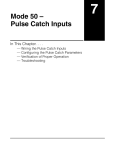
INSTALLATION AND
NETWORK LAYOUTS
In This Chapter:
CHAPTER
3
Inserting the ERM Module in the I/O Base . . . . . . . . . . . . . . . . . . . . . . . . . . . . . . .3–2
DL205/Do-more Slot Choices . . . . . . . . . . . . . . . . . . . . . . . . . . . . . . . . . . . . . . . . .3–2
H2–ERM (100, –F) Module Installation . . . . . . . . . . . . . . . . . . . . . . . . . . . . . . . . . . .3–2
DL405 Slot Choices . . . . . . . . . . . . . . . . . . . . . . . . . . . . . . . . . . . . . . . . . . . . . . . . .3–3
H4–ERM (100, –F) Module Installation . . . . . . . . . . . . . . . . . . . . . . . . . . . . . . . . . . .3–4
Which Modules are Supported in the Ethernet Slaves . . . . . . . . . . . . . . . . . . . . . . .3–4
ERM Network Layouts . . . . . . . . . . . . . . . . . . . . . . . . . . . . . . . . . . . . . . . . . . . . . . . .3–5
Configuring the Ethernet Remote I/O Network . . . . . . . . . . . . . . . . . . . . . . . . . . . .3–5
Running the Ethernet Remote I/O Network . . . . . . . . . . . . . . . . . . . . . . . . . . . . . . .3–5
ERM / ECOM Systems . . . . . . . . . . . . . . . . . . . . . . . . . . . . . . . . . . . . . . . . . . . . . . .3–6
Network Cabling . . . . . . . . . . . . . . . . . . . . . . . . . . . . . . . . . . . . . . . . . . . . . . . . . . . .3–7
ERM Supports Three Standards . . . . . . . . . . . . . . . . . . . . . . . . . . . . . . . . . . . . . . . .3–7
10/100BaseT Networks . . . . . . . . . . . . . . . . . . . . . . . . . . . . . . . . . . . . . . . . . . . . . .3–7
10/100BaseT . . . . . . . . . . . . . . . . . . . . . . . . . . . . . . . . . . . . . . . . . . . . . . . . . . . . . .3–8
UTP Cable . . . . . . . . . . . . . . . . . . . . . . . . . . . . . . . . . . . . . . . . . . . . . . . . . . . . . . . .3–8
10BaseFL . . . . . . . . . . . . . . . . . . . . . . . . . . . . . . . . . . . . . . . . . . . . . . . . . . . . . . . . .3–8
Fiber Optic Cable . . . . . . . . . . . . . . . . . . . . . . . . . . . . . . . . . . . . . . . . . . . . . . . . . . .3–8
Fiber Optic Module ST Connector . . . . . . . . . . . . . . . . . . . . . . . . . . . . . . . . . . . . . .3–8
Maximum Cable Length . . . . . . . . . . . . . . . . . . . . . . . . . . . . . . . . . . . . . . . . . . . . .3–9
Chapter 3: Installation and Network Layout
Inserting the ERM Module in the I/O Base
1
2
3
4
5
6
7
8
9
10
11
12
13
14
A
B
C
D
3–2
DL205/Do-more Slot Choices
The DL205 and Do-more systems support placement of the ERM module in the CPU-base
only. It does not support installation of the ERM in local expansion or remote I/O bases. The
number of usable slots depends on how many slots your base has. See the chart below for
limitations on slot selection. The D2–230 CPU does not support the ERM modules.
205
CPU
Slot 0
Slot 1 Slot 2
Slot 3
Slot 4
No!
WARNING: Your system can be damaged if you install or remove system components before
disconnecting the system power. To minimize the risk of equipment damage, electrical shock, or
personal injury, always disconnect the system power before installing or removing any system
component.
Module Type
H2–ERM(100, -F)
CPU
DL240
DL250-1
DL260
Base
Usable Slots
D2–03B–1, D2–03BDC1–1
D2–04B–1, D2–04BDC1–1
1
1, 2
D2–06B–1, D2–06BDC1–1, D2–06BDC2–1
1, 2, 3, 4
D2–09B–1, D2–09BDC1–1, D2–09BDC2–1
1, 2, 3, 4, 5, 6, 7
Any Base
Any Slot
H2-DM1 / H2-DM1E
H2–ERM (100, -F) Module Installation
205
Retaining Clips
To install the ERM module, line up the module’s printed circuit board with the grooves in
the base and push the module until it is flush with face of the base power supply. If you feel
more than moderate resistance when you push the module into the base, the circuit board
may not be aligned with the grooves in the base. When the module is firmly seated in the slot,
depress the top and bottom retaining clips to lock the module in place.
NOTE: When adding modules to your PLC always confirm that your power budget will accommodate the
added module. See the User Manual for your PLC for more information about calculating the power
budget. See Appendix A for the power consumption of the ERM modules.
Ethernet Remote Master User Manual, 2nd Edition, Rev. A - H24-ERM-M
Chapter 3: Installation and Network Layout
DL405 Slot Choices
For PLC systems with D4–430 and D4–440 CPUs, the ERM modules can reside in any I/O
slot but only in the CPU-base. The D4–450 CPU allows the installation of the ERM module
in the CPU-base or in local expansion bases. If the ERM module is used in a local expansion
base, all bases in the system must be the “–1” type bases. The valid part numbers for these
bases are D4–04B–1, D4–06B–1, and D4–08B–1. The “–1” on the end of the part number
indicates that the base supports specialty modules including the ERM. The “–1” bases can be
connected as local expansion bases or remote bases. They are not the same thing. Remote bases
do not support the ERM modules!
405
CPU
Slot 0
Slot 1
Slot 2
Slot 3
WARNING: Your system can be damaged if you install or remove system components before
disconnecting the system power. To minimize the risk of equipment damage, electrical shock, or
personal injury, always disconnect the system power before installing or removing any system
component.
Module Type
H4–ERM(100, -F)
H4–ERM(100, -F)
H4–ERM(100, -F)
Usable CPU-Base Usable Expansion
Slots
Base Slots
CPU
Base
D4–430/440
D4–04B, D4–04B–1
0, 1, 2, 3
N/A
D4–06B, D4–06B–1
0, 1, 2, 3, 4, 5
N/A
D4–08B, D4–08B–1
0, 1, 2, 3, 4, 5, 6, 7
N/A
D4–04B
0, 1, 2, 3
N/A
D4–06B
0, 1, 2, 3, 4, 5
N/A
D4–08B
0, 1, 2, 3, 4, 5, 6, 7
N/A
D4–04B–1
0, 1, 2, 3
0, 1, 2, 3*
D4–450
D4–450
D4–06B–1
0, 1, 2, 3, 4, 5
0, 1, 2, 3, 4, 5*
D4–08B–1
0, 1, 2, 3, 4, 5, 6, 7
0, 1, 2, 3, 4, 5, 6, 7*
* You must use the “–1” base for the CPU-base and all local expansion bases.
NOTE: Before installing the ERM module, confirm that your power budget will accommodate the added
module. See the PLC user manual for your PLC for more information about calculating the power budget.
See Appendix A for the power consumption of the ERM modules.
Ethernet Remote Master User Manual, 2nd Edition, Rev. A - H24-ERM-M
1
2
3
4
5
6
7
8
9
10
11
12
13
14
A
B
C
D
3–3
Chapter 3: Installation and Network Layout
1
2
3
4
5
6
7
8
9
10
11
12
13
14
A
B
C
D
3–4
H4-ERM(100, -F) Module Installation
To insert the ERM module in a DL405 base, place the bottom tab of the module into the
notch at the bottom of the base. Pivot the module toward the base as shown below. Ensure
that each module is tightly seated and secured with the captive screw at the top of the
module.
DL405 Base
Disconnect power before installing module!
Which Modules are Supported in the Ethernet Slaves
The Ethernet remote I/O slaves accept the most commonly used I/O modules for the
DL205/Do-more, DL405 systems and Terminator I/O systems (AC, DC, AC/DC, Relay an
Analog). The table below lists by category those modules that you may use in a remote I/O
slave. A few specialty modules that are supported in the slaves are listed below.
Module/Unit
Remote Slave
Module/Unit
Remote Slave
PLC CPUs
DC Input Modules
AC Input Modules
AC/DC Input Modules
No
H2–CTRIO(2)
Yes
Yes
D2–CTRINT
No
Yes
H4–CTRIO, D4–HSC
Yes
Yes
No
DC Output Modules
Yes
D2–EM
Communications and
Networking Modules
AC Output Modules
Relay Output Modules
Analog I/O Modules
Thermocouple Module
RTD Module
Yes
No
Yes
Yes
Yes
Yes
NOTE: The User Manual for Analog I/O Modules discusses scan times for updating analog I/O data for
modules installed in local bases. Please be aware that the scan times for updating are different for remote
I/O modules installed in remote bases. The CPU scan is asynchronous with the remote scan by the
master module. Thus, an analog input module installed in a remote base, for example, may not have its
data updated by the CPU “once every scan per channel” as stated in the user manual. The CPU scan may,
in fact, cycle several times while the remote scan is taking place. Take this into account in applications
where the timing is critical.
Ethernet Remote Master User Manual, 2nd Edition, Rev. A - H24-ERM-M
Chapter 3: Installation and Network Layout
ERM Network Layouts
Each ERM module can support up to 16 remote slaves (if a WinPLC system is used, only one
slave can be supported by the ERM module). The slaves supported are the H4–EBC(–F),
H2–EBC(–F), T1H–EBC, GS–EDRV100 and HA–EDRV2. A hub or repeater connects
multiple slaves into a star topology. Multiple hubs or repeaters can be used to create a
star–bus–star topology. Once the ERM I/O network is configured and running, the PC can
be removed from the network.
Configuring the Ethernet Remote I/O Network
Use a PC equipped with a 10/100BaseT or 10BaseFL network adapter card and the Ethernet
Remote Master (ERM) Workbench software configuration utility that comes with this
manual to configure the ERM module and its slaves over the ethernet remote I/O network.
PC running ERM Workbench to
configure the ERM network
DirectLogic or
Do-more PLC
Dedicated
hub(s) for ERM
Network
ERM Module
DL205 I/O
GS-EDRV,
GS-EDRV100
AC Drive
DL405 I/O
Terminator I/O
Running the Ethernet Remote I/O Network
Once the ERM I/O network is configured and running, the PC can be removed from the
network.
Ethernet Remote Master User Manual, 2nd Edition, Rev. A - H24-ERM-M
1
2
3
4
5
6
7
8
9
10
11
12
13
14
A
B
C
D
3–5
Chapter 3: Installation and Network Layout
1
2
3
4
5
6
7
8
9
10
11
12
13
14
A
B
C
D
3–6
ERM / ECOM Systems
Keep ERM networks, multiple ERM networks and ECOM / office networks isolated from
one another as shown below. Do not attempt to connect an ECOM module or non ERM
Workbench PC to a hub that the dedicated ERM network is using. Having an ECOM
module(s) on an ERM Ethernet network can adversely affect the reliability and the speed of
the ERM slave I/O.
Keep ERM and ECOM
modules on separate
Networks
E
R
M
PC for HMI or
SCADA, etc.
E
C
O
M
Dedicated
ERM Network
ECOM or
Office Network
ECOM
Dedicated Hub(s)
for ERM Network
PC for Data Acquisition
in MES, ERP or other
business systems
Warning: We recommend using a dedicated Ethernet remote I/O network for the ERM and its slaves.
While Ethernet networks can handle a very large number of data transmissions, and normally handle
them very quickly, heavy Ethernet traffic can adversely affect the reliability of the slave I/O and the
speed of the network.
Ethernet Remote Master User Manual, 2nd Edition, Rev. A - H24-ERM-M
Chapter 3: Installation and Network Layout
Network Cabling
ERM Supports Three Standards
Three types of ERMs are available. The H2-ERM and H4-ERM support the 10BaseT
standard. The H2-ERM100 and H4-ERM100 support the 10/100BaseT standard. The H2ERM-F supports the 10BaseFL standard. The 10/100BaseT standard uses twisted pairs of
copper wire conductors, and the 10BaseFL standard is for fiber optic cabling.
10/100BaseT
Unshielded twisted-pair
cable with RJ45
connectors
10BaseFL
62.5 / 125 MMF fiber
optics cable with ST-style
connectors
10/100BaseT Networks
The cable used to connect a PLC (or PC) to a hub or repeater is called a patch (straightthrough) cable. The cable used to connect two Ethernet devices (Point–to–Point) together is a
crossover cable. We recommend that you purchase cables pre-assembled with connectors for
convenient and reliable networking.
This diagram illustrates the standard wire positions in the RJ45 connector. We recommend all
ERM 10/100BaseT cables to be Category 5, UTP cable.
Patch (Straight–through) Cable
10/100BaseT
TD+ 1
TD– 2
RD+ 3
4
5
RD– 6
7
8
OR/WHT
OR
GRN/WHT
BLU
BLU/WHT
GRN
BRN/WHT
BRN
RJ45
OR/WHT
OR
GRN/WHT
BLU
BLU/WHT
GRN
BRN/WHT
BRN
1
2
3
4
5
6
7
8
TD+
TD–
RD+
RD–
RJ45
Crossover Cable
1 2 3 4 5 6 78
8-pin RJ45 Connector
(8P8C)
TD+ 1
TD– 2
RD+ 3
4
5
RD– 6
7
8
RJ45
OR/WHT
OR
GRN/WHT
BLU
BLU/WHT
GRN
BRN/WHT
BRN
GRN/WHT
GRN TD+ 1
OR/WHT TD– 2
RD+ 3
BLU
4
BLU/WHT
5
OR
RD– 6
BRN/WHT
7
BRN
8
RJ45
This diagram illustrates the standard wire positions in the RJ45 connector.
We recommend all ERM 10/100BaseT cables to be Category 5, UTP cable.
Ethernet Remote Master User Manual, 2nd Edition, Rev. A - H24-ERM-M
1
2
3
4
5
6
7
8
9
10
11
12
13
14
A
B
C
D
3–7
Chapter 3: Installation and Network Layout
1
2
3
4
5
6
7
8
9
10
11
12
13
14
A
B
C
D
10/100BaseT
Most 10/100BaseT hubs or repeaters use a patch (straight-through) cable for connecting the
network devices (PLCs or PCs). For hub-to-hub connections a crossover type cable is
commonly required. The figures on page 3–6 show pin assignments and insulation color
codes for patch (straight-through) and crossover type Ethernet cables.
UTP Cable
The ERM has an eight-pin modular port that accepts RJ45 type connectors. UTP
(Unshielded Twisted-Pair) cable is rated according to its data-carrying ability (bandwidth) and
is given a “category” number. We strongly recommend using a category 5 cable for all ERM
connections.
10BaseFL
Each module has two bayonet ST-style connectors. The ST-style connector uses a quick
release coupling which requires a quarter turn to engage or disengage. The connectors provide
mechanical and optical alignment of fibers. Each cable segment requires two strands of fiber:
one to transmit data and one to receive data. The ST-style connectors are used to connect the
H2–ERM–F or H4–ERM–F module to another H2–ERM–F or H4–ERM–F module or a
fiber optic hub or repeater.
Fiber Optic Cable
The H2–ERM–F and H4–ERM–F modules accept 62.5/125 multimode fiber optic (MMF)
cable. The glass core diameter is 62.5 micrometers and the glass cladding is 125 micrometers.
The fiber optic cable is highly immune to noise and permits communications over much
greater distances than 10/100BaseT.
Fiber Optic Module ST Connector
Ferrule
Transmit
Sheathing
Core
Receive
62.5/125 MMF cable with
bayonet ST-style connectors
Transmit
Receive
3–8
Fiber cross-section
Multimode Fiber Optic (MMF) Cable
Cladding
Connecting ERM
to Slave
Transmit
Receive
Ethernet Remote Master User Manual, 2nd Edition, Rev. A - H24-ERM-M
Chapter 3: Installation and Network Layout
Maximum Cable Length
The maximum distance per 10/100BaseT cable segment is 100 meters or 328 feet. Repeaters
extend the distance. Each cable segment attached to a repeater can be 100 meters. Two
repeaters connected together extend the total range to 300 meters. For really long distances,
consider using Ethernet/Fiber media converters like the SE-MC2U-ST.
The maximum distance per 10BaseFL cable segment is 2,000 meters or 6,560 feet (1.2
miles). Repeaters extend the distance. Each cable segment attached to a repeater can be 2,000
meters. Two repeaters connected together extend the total range to 6,000 meters.
10/100Base-T Ethernet Control Network shown
(also supports 10Base–FL Networks)
100 meters
(328 ft.)
100 meters
(328 ft.)
10/100Base-T Hub (required
if using more than one
Ethernet slave)
100 meters
(328 ft.)
100 meters
(328 ft.)
100 meters
(328 ft.)
Ethernet Remote Master User Manual, 2nd Edition, Rev. A - H24-ERM-M
1
2
3
4
5
6
7
8
9
10
11
12
13
14
A
B
C
D
3–9
Chapter 3: Installation and Network Layout
1
2
3
4
5
6
7
8
9
10
11
12
13
14
A
B
C
D
Notes
3–10
Ethernet Remote Master User Manual, 2nd Edition, Rev. A - H24-ERM-M