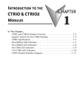
1
GETTING STARTED
CHAPTER
1
Chapter 1: Getting Started
Preliminary
General Information about the CTRIO Module
The Counter I/O (CTRIO) module is
designed to accept high-speed pulsetype input signals and provide
discrete outputs for monitoring,
alarm, or control functions. The
CTRIO module offers great flexibility
for applications which call for precise
counting or timing, based on input
events.
The CTRIO module has its own microprocessor
and operates asynchronously with respect to
the CPU. This means that on-board outputs
respond in approximately 300µs to 2ms.
CTRIO Workbench
All scaling and configuration is done
via a software utility, eliminating the
need for ladder programming to set
up the module. The software utility is
called CTRIO Workbench. The use of
CTRIO Workbench is explained in
Chapter 3.
Supported CPUs
You can use the CTRIO module with
conventional CPUs (D2-240 or D2-250), our state-of-the-art Windows-based CPU
module, or PC-based control strategies.
The CTRIO module plugs into any I/O slot of any DirectLogic 205 base except slot 0
(slot 0 is available for the CTRIO module when using the WinPLC CPU). Slot 0 is the I/O
slot adjacent to the CPU. Multiple CTRIO modules can reside in the same base provided
that the power supply is adequate. CTRIO modules may be placed in secondary local
bases connected via ERM-to-EBC.
The CTRIO module is designed to work with incremental encoders or other field
devices that generate pulses or edges.
Applications:
• cut to length
• piece counting
• positioning a flying punch
• PLS - programmable limit switch (glueing application)
• stepper control
• valve control
1–2
Counter I/O User Manual
Preliminary
Preliminary
Chapter 1: Getting Started
Specifications
General
Module Type
Intelligent
Modules Per Base
Limited only by power consumption
I/O Points Used
None, I/O map directly in PLC V-memory or PC
control access
Field Wiring Connector
Standard removable terminal block
Internal Power Consumption
400mA Max at +5V from 205 Base Power Supply
Maximum of 6 Watts (All I/O in ON State at Max
Voltage/Current)
Operating Environment
32°F to 140°F (0°C to 60°C), Humidity (noncondensing)
5% to 95%
Manufacturer
Host Automation Products, LLC
Isolation
2500V I/O to Logic, 1000V among Input
Channels and All Outputs
Inputs
Primary Inputs
4 pts sink/source 100K Hz Max
Secondary Inputs
4 pts, high speed, for Reset, Inhibit, or Capture
Minimum Pulse Width
5 µsec
Input Voltage Range
9-30VDC
Maximum Voltage
30VDC
Input Voltage Protection
Zener Clamped at 33VDC
Rated Input Current
8mA typical 12mA maximum
Minimum ON Voltage
9.0VDC
Maximum OFF Voltage
3.0VDC
Minimum ON Current
5.0mA (9VDC required to guarantee ON state)
Maximum OFF Current
3.0mA
OFF to ON Response
Less than 3 µsec
ON to OFF Response
Less than 3 µsec
Preliminary
Counter I/O User Manual
1–3
Preliminary
Chapter 1: Getting Started
Specifications (cont’d)
CTRIO Output Specifications
Outputs
4 pts, independently isolated, current sourcing
or sinking (open collector)
Pulse output control
2 channels, 20Hz - 25kHz, pulse and direction
or cw/ccw pulses
Voltage range
5VDC - 36VDC
Maximum voltage
36VDC
Output clamp voltage
60VDC
Maximum load current
1.0A
Maximum load voltage
36VDC
Maximum leakage current
100µA
Inrush current
5A for 20ms
OFF to ON response
less than 3µsec
ON to OFF response
less than 3µsec
ON state V drop
< 0.3V
External power supply
for loop power only, not required for internal
module function*
Overcurrent protection
15A max
Thermal shutdown
Tjunction = 150°C
Overtemperature reset
Tjunction = 130°C
Target position range
+/- 2.1 billion (31 bits + sign bit)
Duty cycle range
0.1% to 99.9% in 0.1% increments
* User supplied 5VDC power source required for most stepper drive configurations
1–4
Counter I/O User Manual
Preliminary
Preliminary
Chapter 1: Getting Started
Specifications (cont’d)
Resources
Counter/Timer
Four (2 per 4 input channel group)
Resource Options
1X, 2X, or 4X Quadrature, Up or Down Counter
Timer Resolution
1 µsec
Counter Range
2.1 billion
LED Descriptions
OK
Module OK
0
Out 0
ER
User Program Error
1
Out 1
C1
Ch 1 A Status / Pulses
2
Out 2
CTR2
Ch 2 A Status / Pulses
3
Out 3
LED Definitions
OK
ER
Description
ON
OFF
All is well - RUN Mode
ON
ON
205 Base Power is Out of +5 Range
Blinking
Blinking
Blinking
OFF
OFF
Blinking
OFF
ON
Module Error Due to Watchdog Timeout
OFF
OFF
No Power to Module
C1 or CTR2
Boot Mode - Used for Field OS Upgrades
Program Mode
Module Self-diagnostic Failure
Based on Configuration of Input A
Blinking 7 times per second
A is Configured as Counter and is Changing
Following State of Input
A is not Configured as Counter
Output LEDs 0 - 3 Follow Actual Output State
Preliminary
Counter I/O User Manual
1–5