1
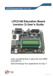
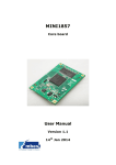
YL-LPC2294 Quick Start Guide
Running YL-LPC2294 on RVDK 2.2 For Philips
Revision 1 — 09 November, 2005
User Guide
Document information
Info
Content
Keywords
LPC2292/94, RVDK, Flash Utility, Microcontroller, MCU.
Abstract
This document describes how to run the YL-LPC2294
Development Board on RealView Development Kit v2.2 for
Philips tool chain environment.
YL-LPC2294 Quick Start Guide
Philips Semiconductors
Running YL-LPC2294 on RVDK 2.2 For Philips
Revision history
Rev
Date
Description
1
20051109
Initial revision.
Contact information
For additional information, please visit: http://www.philips.com/microcontrollers
For sales office addresses, please send an email to: [email protected]
uCDragonQSG
User Guide
© Koninklijke Philips Electronics N.V. 2005. All rights reserved.
Revision 1 — 09 November, 2005
2 of 24
YL-LPC2294 Quick Start Guide
Philips Semiconductors
Running YL-LPC2294 on RVDK 2.2 For Philips
1. Introduction
This YL-LPC2294 Development Board Quick Start Guide provides:
• General information about YL-LPC2294 Development Board hardware features such
as memory, external peripheral configuration, jumper setting, packaging, etc.
• Brief introduction of ARM’s RealView Development Kit (RVDK) version 2.2 for Philips
and RealView ICE Micro Edition (RVI-ME).
• Instructions on how to execute sample programs on the YL-LPC2294 Development
Board and program sample code into the internal flash using RVDK, in conjunction
with Philips LPC2000 Flash Utility for internal flash programming, and GUI utility
DNW (included in the CD package) for external flash programming through YLLPC2294 BIOS running in internal flash.
• Sample Software and Windows testing utilities associated with the Development
board.
2. YL-LPC2294 Development Board
The YL-LPC2294 development board offers the following features:
• MCU: Philips 16/32-bit LPC2294 ARM7TDMI-S with 256 kB built-in program Flash,
16 kB internal RAM, external Memory Bus, RTC, 8×10-bit ADC, 2×UART, 4×CAN,
I2C-bus, SPI, 2×32bit Timers, 7×CCR, 6×PWM, WDT, 5V tolerant I/O, up to 60MHz
operation.
• 512 kB RAM on-board (External RAM)
• 2 MB on-board Flash (External Flash, SST39VF1601)
• Standard 20-pin JTAG connector for both debugging and flash programming
• External USB port (PIDUSB D12)
• Powered through USB port or external 5V DC supply
• Two CAN connectors (with external PCA82C250/1 CAN Transceivers)
• Two RS-232 connector for serial Interfaces
• LCD Module
• Eight push buttons
• Eight LEDs
• PWM Beeper
• CF Card Connector (true IDE Mode, not populated.)
• Two on-board voltage regulators: 1.8 V and 3.3 V with up to 800 mA current
uCDragonQSG
User Guide
© Koninklijke Philips Electronics N.V. 2005. All rights reserved.
Revision 1 — 09 November, 2005
3 of 24
YL-LPC2294 Quick Start Guide
Philips Semiconductors
Running YL-LPC2294 on RVDK 2.2 For Philips
For more details on LPC229x family microcontroller such as data sheet, User’s Manual,
application notes, utilities, please refer to below link at:
http://www.standardics.philips.com/products/mcus/all/~LPC2294/#LPC2294
2.1 YL-LPC2294 Package specification
1. Hardware specification
Item
Processor
Internal RAM
Internal Flash
External RAM
External Flash
LCD Module
Two CAN connector
USB Slave
Two RS232
connector
Description
LPC2294 (up to 60MHz)
16k Bytes
256 kB
512 kB
2 MB
128x64
On-chip
PDIUSBD12
MAX3242 and MAX232
2. YL-LPC2294 development kit contents
Item
Main Board
RVI-ME
CD
Description
YL-LPC2294 Board
ARM’s RealView In-Circuit Emulator
Include RVDK IDE, sample software, utility, and
Documentation
Serial cable (cross)
USB cable x 2
JTAG Cable between RVI-ME and main board
Cables
2.2 Jumper Setting
For configuration purposes, the YL-LPC2294 has four jumpers. Some of them have been
installed prior to delivery.
The jumpers (J=solder jumper) have the following functions:
uCDragonQSG
User Guide
© Koninklijke Philips Electronics N.V. 2005. All rights reserved.
Revision 1 — 09 November, 2005
4 of 24
Philips Semiconductors
YL-LPC2294 Quick Start Guide
Running YL-LPC2294 on RVDK 2.2 For Philips
Symbol
JP1
Default Setting
1+2 (INTRE_BOOT): Boot from
Internal Flash
Open (Not installed)
JP2
(RESET_EN)
JP3
Open: ISP disable
(ISP_EN)
JP4
1+2 (EXT_POWER): Power
through USB port*
Alternative Setting
2+3 (EXTRE_BOOT): Boot
from External Flash
Close: ISP enable
2+3 (USB_POWER): Power
through External 5V DC
supply
*: The label mask on the board is reversed.
2.3 External Memory Banks
The Philips LPC2292/94 microcontroller provides up to four Chip Select signals
(CS0 to CS3) for easy selection of external peripherals or memory banks. All the
uCDragonQSG
User Guide
© Koninklijke Philips Electronics N.V. 2005. All rights reserved.
Revision 1 — 09 November, 2005
5 of 24
Philips Semiconductors
YL-LPC2294 Quick Start Guide
Running YL-LPC2294 on RVDK 2.2 For Philips
chip select signals are used. CS0 (bank 0) is used for 2 MB external Flash,
SST39VF1601 on U7. CS1 (bank 1) is used for 512 kB external RAM,
IS61LV51216-12T on U6. CS2 (bank 2) is used for optional Ethernet device U13
(not populated), CS3 (bank 3) and some address lines are used for selecting
D12 USB and LCD module on U16 and U17, as well as for expansion connector.
2.4 External Memory Registers and Address Range
The following table shows the pre-defined address ranges for the individual /CS
signals (banks) and the corresponding bus configuration registers:
uCDragonQSG
User Guide
© Koninklijke Philips Electronics N.V. 2005. All rights reserved.
Revision 1 — 09 November, 2005
6 of 24
Philips Semiconductors
YL-LPC2294 Quick Start Guide
Running YL-LPC2294 on RVDK 2.2 For Philips
2.5 Extended User Pin Map
YL-LPC2294 provides a 50-pin connector (CN3) which allows users to connect
external devices to Philips LPC2294 MCU. In addition to the VCC and ground
signals, all the 16 data lines D0-D15, address lines A1-A22, Write Enable (WE)
and Output Enable (OE) pins of LPC2294, and CS3 pin, are routed out the
connector. The next Table provides an overview of the extended user pins.
Please refer to the Philips Data Sheet for more details on the functions and
features of MCU signals and port pins.
Pin Number
1,2,3
Signal
VDD5V, VDD3V3,
GND
P0.29/AIN2,
P0.28/AIN1
I/O
-
6
P0.20/EINT3
I/O
7,8
P3.28/AIN7,
P3.29/AIN6
I/O
9
10
NGCS_USER
BUF_OE
O
O
11
BUF_WE
O
12
BUF_nRESET
O
13∼34
ADDR1~ADDR22
I/O
35∼50
DATA0~DATA15
I/O
4,5
Description
Voltage input +5V,Voltage
input 3.3V,Ground 0V
Port P0 of the
microcontroller,
(Alternative function:
analog inputs AIN1, AIN2)
Port P0 of the
microcontroller,
(Alternative function:
External Interrupt EINT3)
Port P3 of the
microcontroller,
(Alternative function:
analog inputs AIN7, AIN6)
/CS3, Chip Select #3
Output enable signal of
the microcontroller
/WR signal of the
microcontroller
Reset Signal Output of YLLPC2292
Address line of the
microcontroller
Data line of the
microcontroller
I/O
The other group of Extended User Pins on JP5 (30 pins)
Pin Number
1,2,3,4,5
6
Signal
GND
P028/AIN1
uCDragonQSG
User Guide
Ι/Ο
−
Ι/Ο
Description
Ground 0V
Port P0 of the
microcontroller,
(Alternative function:
© Koninklijke Philips Electronics N.V. 2005. All rights reserved.
Revision 1 — 09 November, 2005
7 of 24
Philips Semiconductors
YL-LPC2294 Quick Start Guide
Running YL-LPC2294 on RVDK 2.2 For Philips
7,8
P3.29, P3.28
Ι/Ο
9,10,11,12,13
I/O
21
P2.27, P2.26, P2.25,
P2.24, P2.23
P1.19, P1.25, P1.22,
P1.21, P1.20, P1.17,
P0.22
P0.20/EINT3
I/O
22,23,24,25,26
27,28,29,30
VDD3V3
VDD5V
-
14,15,16,17,18,1
9,20
analog inputs AIN1,
AIN2)
Port P3 of the
microcontroller,
Port P2 of the
microcontroller,
Port P1 and P2 of the
microcontroller,
Port P0 of the
microcontroller,
(Alternative function:
External Interrupt EINT3)
Voltage input 3.3V
Voltage input 5.0V
3. Getting started
3.1 How to start YL-LPC2294
This section introduces how to start YL-LPC2294.
1) Ensure proper jumper settings on the YL-LPC2294 Development Board as
below:
JP1 jumper: 1+2 (INTRE_BOOT), boot from internal flash
JP2 jumper: open, N/A
JP3 jumper: open, ISP Disabled
JP4 jumper: 1+2 (EXT_POWER), powered through USB port (label
reversed)
2) Connect the RS-232 interface of your computer to the DB-9 RS-232 interface
(COM1) on YL-LPC2294 Development Board using the included serial cable.
3) Run the Windows based serial utility, DNW, included in the CD or you can
download from Philips Website, on a PC with the following setting:
115,200/8/N/1, no flow control. (Please note, USB Port functionality on the
DNW is not yet available.)
4) The sample BIOS program has been pre-programmed on the YL-LPC2294
Development Board. After DNW starts, click “Serial Port”, select “Connect”,
then push the red reset button on the board again. When the BIOS starts to
run, all the LEDs blink, the LCD module displays “Philips LPC229x,
www.semiconductors.philips.com”, and the DNW utility displays as follows:
uCDragonQSG
User Guide
© Koninklijke Philips Electronics N.V. 2005. All rights reserved.
Revision 1 — 09 November, 2005
8 of 24
Philips Semiconductors
YL-LPC2294 Quick Start Guide
Running YL-LPC2294 on RVDK 2.2 For Philips
3.2 Programming BIOS into Internal Flash
If, for whatever reason, the internal flash has not been programmed, and/or has
been erased, there are several ways to reprogram the application image into the
internal flash of LPC2294:
•
•
Using Philips Flash Utility via UART
Using RVDK v2.2 for Philips Flash Utility via JTAG. (To be described in
the section later)
The Philips Flash Utility can be found under:
http://www.standardics.philips.com/products/mcus/all/~LPC2294/#LPC2294
After installation, change the jumper setting: JP3: Close, ISP Enabled, make
sure RS-232 cable is still connected between the PC and YL-LPC2294, and
neither PC Hyper Terminal window software nor DNW utility should be open,
then, push the red reset button to reboot the board.
To start the Philips Flash Utility, simply double click “LPC210x_ISP.exe”, and the
ISP program will appear as shown below.
uCDragonQSG
User Guide
© Koninklijke Philips Electronics N.V. 2005. All rights reserved.
Revision 1 — 09 November, 2005
9 of 24
Philips Semiconductors
YL-LPC2294 Quick Start Guide
Running YL-LPC2294 on RVDK 2.2 For Philips
Just use the setting above and make sure “Use DTR/RTS for Reset and Boot
Loader Selection” is checked. The YL-LPC2294 Development Board BIOS
sample image can be found under
“YL_LPC229X_BIOS/Release/YL_LPC229X_BIOS.hex”. Browse and select that
file name under “Flash Programming”, then click “Update To Flash” to program
the BIOS into the LPC2294 internal flash. You will see the file upload progress in
the lower bar of the Flash Utility window. When complete, the bar will indicate
“File Upload Successfully Completed”.
Once the flash program is finished, make JP3 (ISP_EN) OPEN to disable ISP.
Reset the board. The BIOS sample image will be executed, and DNW should be
seen as in Chapter 3.1
Warning: Don’t forget to CLOSE JP3 jumper to enable the ISP, if you want
to run the Philips ISP Flash Utility again.
3.3 Program code into external Flash by BIOS
This section will introduce how to download sample software into external flash
on YL-LP2294 development board.
1) Once the BIOS program runs, from DNW, type in “help” to see a list of
the commands, and type in “comload” command under the prompt
symbol “/>” and press “Enter” key.
uCDragonQSG
User Guide
© Koninklijke Philips Electronics N.V. 2005. All rights reserved.
Revision 1 — 09 November, 2005
10 of 24
Philips Semiconductors
YL-LPC2294 Quick Start Guide
Running YL-LPC2294 on RVDK 2.2 For Philips
2) Click “Serial Port-->Transmit” on the DNW, then select “LED_External.bin”
(Sample LED blink code on YL-LPC2294) file to download from below:
\LED\Release\LED_External.bin. When the download is complete, message
“Received xxx bytes success” will be shown as below.
3) Type in “prog 80000000” command under the prompt symbol “/>”, and
press “Enter” Key, right after next prompt “Are you sure? [y/n] “, type in
“y” to confirm, Then, the sample program is programmed into the
external Flash (SST39VF1601). As mentioned earlier, the external flash
is on external memory bank0, its address range is from 0x8000 0000 to
0x8020 0000. Once the programming is complete, it will return message
“OK” on DNW.
uCDragonQSG
User Guide
© Koninklijke Philips Electronics N.V. 2005. All rights reserved.
Revision 1 — 09 November, 2005
11 of 24
Philips Semiconductors
YL-LPC2294 Quick Start Guide
Running YL-LPC2294 on RVDK 2.2 For Philips
4) Change the jumper setting, close JP1 jumper 2+3 (EXTRE_BOOT) to
external reboot, then press the red reset button. After reset, the system
will boot from external Flash, and the LED example will result in LEDs
D1~D8 on the Development Board blinking on and off in a circular fashion
at equal intervals.
Warning: Don’t forget to change the JP1 jumper back to default setting
INTRE_BOOT position, if you want to resume the program executing from
the internal flash.
4. Function of YL-LPC2294 BIOS
4.1 List of BIOS functions
Below is a list of these commands in the YL-LPC2294 BIOS.
help:
Show list of the commands.
clock:
Show clock information, such as the frequency of the crystal, system
clock, CCO, and VPB.
comload: Download file through UART.
Usage: comload [external SRAM addresss1]
uCDragonQSG
User Guide
© Koninklijke Philips Electronics N.V. 2005. All rights reserved.
Revision 1 — 09 November, 2005
12 of 24
Philips Semiconductors
YL-LPC2294 Quick Start Guide
Running YL-LPC2294 on RVDK 2.2 For Philips
For example: “comload 81000000” or “comload” (default address
0x81000000)
comrun: Download file through UART then run
Usage : comrun [external SRAM address]
For example: “comrun 81000000” or “comrun” (default address
0x81000000)
prog:
Program flash
Usage: prog [external flash address] [external SRAM address] [length]
For example: “prog 80000000 81000000 10000”
To simplify the process, to program the code into flash, only specify
external flash starting address as: “prog 80000000”
run:
Run program
Usage: run [external SRAM address]
For example: “run 81000000”
5. RealView Development Kit For Philips
5.1 Overview
RVDK for Philips 2.2 consists of the software development tool chains, compiler,
linker, debugger, and RealView ICE Micro-Edition. It enables you to write, build,
and debug applications for Philips ARM architecture-based RISC processors. It
is specifically designed for Philips microcontrollers, and is not compatible with
ARM microcontrollers from other vendors.
RVDK 2.2 supports the compilation of C and ARM Assembly source files and
debugging on Philips’ ARM based processors exclusively. RVDK is supported on
Windows 2000 and Windows XP Professional operating systems only.
RealView Debugger v1.8, together with RealView ICE Micro Edition v1.1 has a
user- friendly graphic user interface that enables you to debug your embedded
application programs and have complete control over the flow of the program
execution so that you can quickly isolate and correct the errors.
For more details about RVDK For Philips 2.2, please refer to “RealView®
Developer Kit for Philips, Version 2.2, Getting Started Guide”.
5.2 Getting started with RVDK
Using the USB cable included in the package to connect between PC and RVIME first, then connect the 20-pin JTAG cable between the RVI-ME and YLLPC2292 Development Board. After the installation of the RVDK tool chain and
USB driver for RVI-ME, you can start the RealView Debugger v1.8 by double
uCDragonQSG
User Guide
© Koninklijke Philips Electronics N.V. 2005. All rights reserved.
Revision 1 — 09 November, 2005
13 of 24
Philips Semiconductors
YL-LPC2294 Quick Start Guide
Running YL-LPC2294 on RVDK 2.2 For Philips
clicking from “ARM/RealView Development Kit v2.2 For Philips/RealView
Debugger v1.8”. Debugger will be shown as below.
Click “Target”, then the “Connection Control” window will pop out, go to “RVIME”, right click, then select “Connection Properties”, go to “CONNECTION=RVIME”, click “BoardChip Name” on the right side, and select “LPC2294”. This
indicates RVI-ME is going to connect to the LPC229x based target board. Save
the configuration as seen below, and close the “Connection Properties” windows.
If the “BoardChip Name” LPC2294 is not listed, it indicates that the LPC2294
BCD file has not been installed in the correct directory under RVDK. In the
default installation directory, all the processor specific or board specific BCD files
should be found under:
“C:\Program Files\ARM\RVD\Core\1.8\848\phil_mcu\win_32-pentium\etc”
More details about RVDK connection properties should refer to “Connecting to a
debug target” in “RealView® Developer Kit for Philips, Version 2.2, Getting
Started Guide”.
uCDragonQSG
User Guide
© Koninklijke Philips Electronics N.V. 2005. All rights reserved.
Revision 1 — 09 November, 2005
14 of 24
Philips Semiconductors
YL-LPC2294 Quick Start Guide
Running YL-LPC2294 on RVDK 2.2 For Philips
After the configuration, you can close the “Connection Properties” window,
shown above, and confirm to save the configuration.
While in the “Connection Control” window, go to “RVI-ME”, right click, then select
“Configure Device Information”. If no devices appear on the JTAG chain on the
right side of the window, click “Auto Configure Scan Chain”; “ARM7TDMI-S”
should appear after a few seconds as shown below.
uCDragonQSG
User Guide
© Koninklijke Philips Electronics N.V. 2005. All rights reserved.
Revision 1 — 09 November, 2005
15 of 24
Philips Semiconductors
YL-LPC2294 Quick Start Guide
Running YL-LPC2294 on RVDK 2.2 For Philips
Once the connection setup is done, you are ready to open the sample project
and connect the target board through RealView Debugger.
Click “Project”, select “Open Project”, you can select the LED sample project
provided in the RVDK CD-ROM for Philips YL-LPC2294 board. “LED.prj” is the
LED blinky project created on RVDK for code running in either internal flash
(Release) or internal SRAM (Debug). “LED_External.prj” is the RVDK project for
code running in either external flash (Release) or external SRAM (Debug). We
primarily use “LED.prj” as the example to demonstrate not only how to use
RealView debugger to single step through and control the flow of the program,
but also how to use the built-in flash utility to program the internal flash of
LPC2294.
Go to the LED sample project directory, open “LED.prj” as shown above. Go to
toolbar “Build” next to “Project”, click “Build” or “Rebuild” to compile the sample
project. Default project setting will build a loadable debug image to be executed
on the internal SRAM. The loadable image will reside in the “Debug” directory,
and the flash image will reside in the “Release” directory. The very first time,
RVDK will pop out a message “Makefile doesn’t exist, would you like to build it?”,
click “yes” to confirm. The complete build process can be seen on the “Build”
window.
uCDragonQSG
User Guide
© Koninklijke Philips Electronics N.V. 2005. All rights reserved.
Revision 1 — 09 November, 2005
16 of 24
Philips Semiconductors
YL-LPC2294 Quick Start Guide
Running YL-LPC2294 on RVDK 2.2 For Philips
5.3 Connect RVI-ME to a Target Board
Once the project is open, click hyperlink “Click to connect to a target”. The
debugger will try to connect to the target board. It will take a few seconds to
connect to the board. Once the connection is established, the check box next to
“ARM7TDMI-S” should be checked, and the screen is shown as below.
Clicking hyper link “…\Debug\LED.axf” as seen above will load the LED sample
image onto the internal SRAM of LPC2294 for execution. Clicking “Debug”,
“Toggle Source/Disassembly”, the source window will show mixed code. At
address 0x4000 0000, the first instruction is “Reset LDR PC, ResetAddr”,
indicating the image has been loaded onto the internal SRAM area successfully.
Go to “Debug”, select “Run” or simply press the “F5” key on the keyboard, the
LED blink program will be executed on the debugger, the result can be seen on
the YL-LPC2294 board.
5.4 Program Internal Flash using RVDK
Once the Board Chip Definition (BCD), the BCD file, has been set in the
connection properties for a specific target board, the Flash Method (FME) file will
uCDragonQSG
User Guide
© Koninklijke Philips Electronics N.V. 2005. All rights reserved.
Revision 1 — 09 November, 2005
17 of 24
Philips Semiconductors
YL-LPC2294 Quick Start Guide
Running YL-LPC2294 on RVDK 2.2 For Philips
be referenced as well when the BCD file specifies where the internal flash is
located. By default installation directory, all the processor specific FME files
should be found under:
“C:\Program Files\ARM\RVD\Flash\1.8\7\windows”
The FME code will run to program the flash when you select the Flash
Programming window in the RealView Debugger environment. For more details
about FME, please refer to ARM’s Application Note 110, “Flash Programming
with RealView Debugger”.
5.4.1 Build Release Image for Flash Programming
To build a flash image, go to “Target”, click “Disconnect” to disconnect the target
connection first, make JP3 (ISP_EN) CLOSE to enable ISP, push the red
“Reset” button to reset the board, and make sure the debugger has stopped.
Please note: the jumper setting and reset process is imperative to make sure the
board is in a clean state before the flash programming.
Then, go to “Project” toolbar next to it, click “Project Properties”, then select
“Configuration” as seen above. Change “Active config” from “Debug” to
“Release”, then save the configuration of the “Project Properties”, click “Build” or
“Rebuild” to build the release image. This will create the image that can be
programmed into the internal flash.
uCDragonQSG
User Guide
© Koninklijke Philips Electronics N.V. 2005. All rights reserved.
Revision 1 — 09 November, 2005
18 of 24
Philips Semiconductors
YL-LPC2294 Quick Start Guide
Running YL-LPC2294 on RVDK 2.2 For Philips
5.4.2 Program Internal Flash with RVDK
Use the same procedure mentioned above to reconnect the target board. If the
“Register” window is not open on the RealVIew debugger, go to “View”, select
“Registers”. There are three sections, “Core”, “Debug”, and “LPC2294”, which
can be viewed on the registers window. Select “LPC2294”, and the register
window will be shown as below:
Go to “Memory Map” and make sure “Memory Mode” is set to 0x01 or “User
Flash”. This is to ensure Memory Map Control register is set to “User Flash
Mode”, and interrupt vectors are not remapped and reside in internal flash. For
more details, please refer to System Control Block chapter, “LPC229x User
Manual”.
Once the Memory Map register setting is done, click hyper link “Click to load
…\Release\LED.axf”, as seen from below screen,
uCDragonQSG
User Guide
© Koninklijke Philips Electronics N.V. 2005. All rights reserved.
Revision 1 — 09 November, 2005
19 of 24
Philips Semiconductors
YL-LPC2294 Quick Start Guide
Running YL-LPC2294 on RVDK 2.2 For Philips
The Flash Memory Control Window will pop out automatically as below, enter the
crystal frequency on the board, on YL-LPC2294 board, the frequency is
14.745 Mhz, the Click “Write” will program the Release image “LED.axf” to the
internal flash of LPC2294.
Remove the ISP_EN jumper, press the red “Reset” button again to reset the
board, the code will run in the internal flash. The blinking LEDs indicate that the
code is running from SRAM in the debug mode.
At the time of writing, there are some issues that flash programming will not
complete, if the wrong clock frequency is entered. In the flash log, “Flash
Programming complete” never appears. If that happens, quit RealView Debugger
and start all over again.
uCDragonQSG
User Guide
© Koninklijke Philips Electronics N.V. 2005. All rights reserved.
Revision 1 — 09 November, 2005
20 of 24
Philips Semiconductors
YL-LPC2294 Quick Start Guide
Running YL-LPC2294 on RVDK 2.2 For Philips
5.5 Build Images for External Memory
As mentioned earlier, “LED_External.prj” is the RVDK project for code running in
either external flash (Release) or external SRAM (Debug). You can use this
sample project to either build a loadable image (Debug) and execute on the
external SRAM, or change the setting in “Active Config” to “Release” in the
“Project Properties” to build a flash image (Release), and use YL_LPC2294
BIOS sample program along with DNW utility to execute the program in external
SRAM and/or program and execute the code in external flash.
uCDragonQSG
User Guide
© Koninklijke Philips Electronics N.V. 2005. All rights reserved.
Revision 1 — 09 November, 2005
21 of 24
Philips Semiconductors
YL-LPC2294 Quick Start Guide
Running YL-LPC2294 on RVDK 2.2 For Philips
6. Disclaimers
Life support — These products are not designed for use in life support appliances,
devices, or systems where malfunction of these products can reasonably be expected to
result in personal injury. Philips Semiconductors customers using or selling these
products for use in such applications do so at their own risk and agree to fully indemnify
Philips Semiconductors for any damages resulting from such application.
Right to make changes — Philips Semiconductors reserves the right to make changes
in the products - including circuits, standard cells, and/or software - described or
contained herein in order to improve design and/or performance. When the product is in
full production (status ‘Production’), relevant changes will be communicated via a
Customer Product/Process Change Notification (CPCN). Philips Semiconductors
assumes no responsibility or liability for the use of any of these products, conveys no
license or title under any patent, copyright, or mask work right to these products, and
makes no representations or warranties that these products are free from patent,
copyright, or mask work right infringement, unless otherwise specified.
Application information — Applications that are described herein for any of these
products are for illustrative purposes only. Philips Semiconductors make no
representation or warranty that such applications will be suitable for the specified use
without further testing or modification.
7. Trademarks
All referenced brands, product names, service names and trademarks are the property of
their respective owners.
uCDragonQSG
User Guide
© Koninklijke Philips Electronics N.V. 2005. All rights reserved.
Revision 1 — 09 November, 2005
22 of 24
Philips Semiconductors
YL-LPC2294 Quick Start Guide
Running YL-LPC2294 on RVDK 2.2 For Philips
8. References
•
ARM RealView Development Kit For Philips, Version 2.2, Getting Started
Guide, ARM Limited, Sept. 2005.
•
ARM Application Note 110, Flash Programming With RealView
Debugger, ARM Limited, April, 2003 http://www.arm.com
•
ARM Application Note 142, Generating and Using BCD files with
RealView Debugger, ARM Limited, Feb., 2005 http://www.arm.com
•
ARM FAQ: http://www.arm.com/ARM7TDMI-S.html
•
Philips LPC2292/2294 User Manual, Philips Semiconductor, May, 2005.
http://www.standardics.philips.com/support/techdocs/microcontrollers/pdf/
user_manual_lpc2119_2129_2194_2292_2294.pdf
•
Philips Application Note AN10356, Entering ISP from User Mode, Philips
Semiconductor, Feb., 2005
uCDragonQSG
User Guide
© Koninklijke Philips Electronics N.V. 2005. All rights reserved.
Revision 1 — 09 November, 2005
23 of 24
Philips Semiconductors
YL-LPC2294 Quick Start Guide
Running YL-LPC2294 on RVDK 2.2 For Philips
9. Contents
1.
Introduction .........................................................3
2.
2.1
2.2
2.3
2.4
2.5
3.
3.1
3.2
3.3
4.
4.1
YL-LPC2294 Development Board.......................3
YL-LPC2294 Package specification....................4
Jumper Setting....................................................4
External Memory Banks ......................................5
External Memory Registers and Address Range 6
Extended User Pin Map ......................................7
Getting started.....................................................8
How to start YL-LPC2294 ...................................8
Programming BIOS into Internal Flash ...............9
Program code into external Flash by BIOS .......10
Function of YL-LPC2294 BIOS .........................12
List of BIOS functions .......................................12
5.
5.1
5.2
5.3
5.4
5.4.1
5.4.2
5.5
6.
RealView Development Kit For Philips ............13
Overview ...........................................................13
Getting started with RVDK ................................13
Connect RVI-ME to a Target Board ..................17
Program Internal Flash using RVDK .................17
Build Release Image for Flash Programming....18
Program Internal Flash with RVDK ...................19
Build Images for External Memory ....................21
Disclaimers ........................................................22
7.
Trademarks ........................................................22
8.
References .........................................................23
9.
Contents .............................................................24
uCDragonQSG
User Guide
© Koninklijke Philips Electronics N.V. 2005. All rights reserved.
Revision 1 — 09 November, 2005
24 of 24