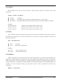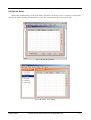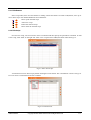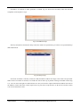
1
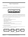
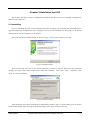
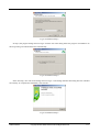
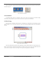
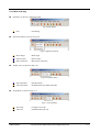
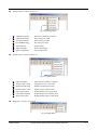
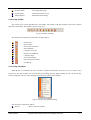
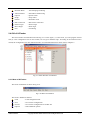
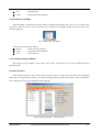
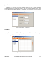
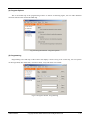
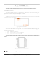
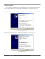
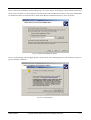
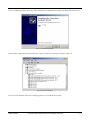
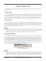
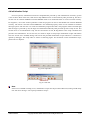
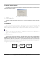
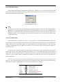
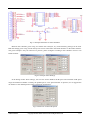
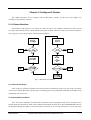
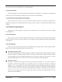
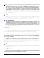
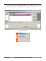
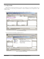
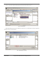
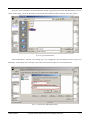
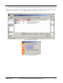
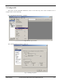
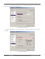
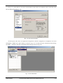
H-JTAG USER MANUAL WWW.HJTAG.COM H-JTAG USER MANUAL Copyright © 2009 WWW.HJTAG.COM All Rights Reserved Release Information Date Issue Change 2007-10-01 A Release first edition 2007-11-30 B Revised edition 2008-03-03 C Corrected the illustration of TAP configuration 2009-01-08 D Updated for new software version Property Notice 1. 2. 3. 4. 5. JTAG is a standard (IEEE-1149) proposed by IEEE. The copyright belongs to IEEE. All the registered trademarks and logos mentioned in this manual belong to their respective owners. All the products and services described in this manual also belong to their respective owners. If this manual harms your copyright, please contact us and we will make the correction accordingly. This manual is an open document. User can redistribute it freely if only the integrality can be guaranteed. Official Website HTTP://WWW.HJTAG.COM Support Forum HTTP://FORUM.HJTAG.COM USER MANUAL Copyright © 2009 WWW.HJTAG.COM All Rights Reserved I Contents Preface A B C About this Manual ………………….…………….…..…….…………….…..….……...… IV Using this Manual …….….………….………………...….…………….……..………...… IV Feedback …………………...…………….……………..........………….………..……...… IV Chapter 1 H-Jtag Introduction 1.1 About H-Jtag .................………………………………………………………….……..… 1-1 1.2 Communication Structure ..............................…………………………………….……… 1-1 Chapter 2 Installation and GUI 2.1 Installation .............................................................................................................…........... 2-1 2.2 Uninstallation ......…..……………………………………............………………………… 2-3 2.3 GUI of H-Jtag ....................................................................................................................... 2-3 2.4 GUI of H-Flasher ...........………………………………………………………………...… 2-7 Chapter 3 H-Jtag Emulator 3.1 Hardware Interface .................………………………………………………….……..… 3-1 3.2 Driver Installation ..........................................…………………………………….……… 3-2 Chapter 4 Configure H-Jtag 4.1 Detect Target ………………………………………………………………………………. 4-1 4.2 Reset Target ………….……………………………………………………………………. 4-1 4.3 Auto Flash Download ………………………...…………………………………………… 4-1 4.4 Initialization Script …….…………………………………………………………………. 4-2 4.5 USB/LPT Interface Selection .........………………………………………………………. 4-3 4.6 JTAG Configuration .......…………………………………………………………………. 4-3 4.7 LPT Port Setting ...............……..…………………………………………………………. 4-6 4.8 Target Setting .............……..………………………………………………………………. 4-6 4.9 Target Manager …………………………………………………………………………… 4-6 4.10 TAP Configuration …………..………………………………………………………….… 4-7 4.11 H-Jtag Options .………………..…….……………………………………………………. 4-8 4.12 Check for Updates .……………...………....……………………………………………. 4-9 Chapter 5 Configure H-Flasher 5.1 Workflow of H-Flasher .......……….……………………………………………………… 5-1 5.2 H-Flasher Program Wizard …....………………………………………………………… 5-2 5.3 Useful Tips ………………………………………………………………………………… 5-5 5.4 Example 1 - AT91SAM7X256 …..………………………………………………………... 5-6 5.5 Example 2 - LPC2210 + SST39VF1601………………………………………………... 5-10 USER MANUAL Copyright © 2009 WWW.HJTAG.COM All Rights Reserved II Chapter 6 Initialization Script 6.1 Definition of Script Commands ………………..………………………………………… 6-1 6.2 Edit Initialization Script ………………………......……………………………………… 6-3 Chapter 7 Configure Debuggers 7.1 Configure AXD ……………………………………..……………………………………... 7-1 7.2 Configure RVDS ………………..…………………………….……....…………………… 7-4 7.3 Configure IAR …………………..……………………………....………………………… 7-8 7.4 Configure KEIL …………………..……………………………………………………… 7-12 USER MANUAL Copyright © 2009 WWW.HJTAG.COM All Rights Reserved III Preface A. About this manual H-Jtag user manual introduces how to configure and use H-Jtag and H-Flasher. Some illustrative examples are also given in this manual for reference. For more information, please visit www.hjtag.com or forum.hjtag.com. B. Using this manual This manual is intended to assist user in the use of H-Jtag and H-Flasher. If you are a beginner, this manual is a good quick start guide. If you are not a beginner, you can use this manual as a reference and read it selectively. C. Feedback If you find any error or omission in this document, please contact us. Any suggestions and comments are welcome. The contact email address is [email protected]. USER MANUAL Copyright © 2009 WWW.HJTAG.COM All Rights Reserved IV Chapter 1 H-Jtag Introduction 1.1 About H-Jtag H-Jtag is a debug agent, likes the popular Multi-ICE. H-Jtag includes three tools, H-Jtag server, H-Flasher and H-Converter (Fig 1-1). H-Jtag server acts as a debug agent, while H-Flasher acts as a flash programmer. H-Converter is a conversion tools, which supports common file formats like BIN, HEX and ELF. Fig 1-1 H-JTAG Structure H-Jtag supports the debug of all the ARM7,ARM9, XSCALE and CORTEX-M3 based chips and can be used with most of the popular debuggers, for example ADS, RVDS, IAR and KEIL. H-Jtag provides flexible configuration, with which H-Jtag can work with Wiggler, SDT-Jtag, other user-defined JTAG interface boards and USB H-JTAG emulator. The included H-Flasher supports the programming of most common flash chips. With H-Jtag, it is easy to build up a debug platform. Summed up, H-Jtag has following features. 1. Support RDI 1.5.0 and RDI1.5.1; 2. Support all AR7, ARM9, XSCALE and CORTEX-M3 chips; 3. Support THUMB and ARM instructions; 4. Support Little-Endian and Bit-Endian; 5. Support Semihosting; 6. Support Wiggler, SDT-Jtag, user defined JTAG interface boards and USB H-JTAG emulator; 7. Support WINDOW 9.X/NT/2000/XP; 8. Support the programming of most common flash chips; 9. Support auto flash download for LPC2000, AT91SAM, LUMINARY and STM32F series; 1.2 Communication Structure H-Jtag supports RDI interface from ARM Limited. Through the RDI interface, H-Jtag can support most of the popular debuggers. The connection for debugging is shown in Fig 1-2. Fig 1-2 Connection for Debugging USER MANUAL Copyright © 2009 WWW.HJTAG.COM All Rights Reserved 1-1 Debuggers communicate with H-Jtag server via RDI. H-Jtag server accesses the JTAG port of target system through the JTAG controller connected to LPT/USB. With proper configuration, H-Jtag can work with different LPT JTAG emulators or H-JTAG USB JTAG emulator. Besides debugging, H-Flasher can download data/program into flash chip. Currently, H-Flasher supports most common on-chip flashes and external flashes. In the future, H-Flasher will support more and more chips. For programming, the connection between H-Flasher and H-Jtag server is shown in Fig 1-3. Fig 1-3 Connection between H-Flasher and H-Jtag Server As shown in the above figure, H-Flasher also talks to H-Jtag server via RDI. The communication is similar to that for debugging. USER MANUAL Copyright © 2009 WWW.HJTAG.COM All Rights Reserved 1-2 Chapter 2 Installation and GUI This chapter introduces both the installation/uninstallation and the GUI. For the detailed configurations, please refer to Chapter 4-7. 2.1 Installation User can download the latest version installation file from www.hjtag.com. Normally, the downloaded file is zipped and need to be unzipped first. After unzipped, user can get the installation exe file h-jtag.exe. By double clicking the exe file, the installation can be started. First, user will see the welcome dialog, as shown in Fig 2-1. Click “Next” and go to next step. Fig 2-1 Installation Step-1 In the second step, user will see the license agreement, as shown in Fig 2-2. Please read the agreement carefully. To accept it, tick “I agree with the above terms and conditions.” Then click “Next”. Otherwise, click “Exit” to exit the installation. Fig 2-2 Installation Step-2 In the third step, user will see the destination folder dialog (shown in Fig 2-3). In this dialog, user can choose the destination folder. After choosing the destination folder, click “Next” and go to next step. USER MANUAL Copyright © 2009 WWW.HJTAG.COM All Rights Reserved 2-1 Fig 2-3 Installation Step-3 In step-4, the progress dialog shown in Fig 2-4 will be seen. This dialog shows the progress of installation. In this step, H-Jtag will install all the files automatically. Fig 2-4 Installation Step-4 In the final step, user will see the dialog shown in Fig 2-5. The dialog indicates that H-Jtag has been installed successfully. To complete the installation, click “Finish”. Fig 2-5 Installation Step-5 USER MANUAL Copyright © 2009 WWW.HJTAG.COM All Rights Reserved 2-2 After the installation, shortcuts will be created on the desktop and the start menu respectively. The shortcuts are shown in Fig 2-6. Fig 2-6 Shortcuts of H-Jtag 2.2 Uninstallation To uninstall H-Jtag, please run unstall.exe from the start menu. This program will uninstall H-Jtag automatically. During the process, please follow the instructions to perform the uninstallation. 2.3 GUI of H-Jtag The main window of H-Jtag is shown in Fig 2-7. In the figure, (1) is the menu, (2) is the toolbar, (3) is the detected ARM core, (4) is the device ID and (5) shows the connected debugger, RDI version and hardware interface. Fig 2-7 Main window of H-Jtag The menu includes all the operations and configurations, and the toolbar includes most of the common ones. When a connected target is detected, H-Jtag displays the ARM core and 32-bit device ID in the middle of the main window. When no target is detected or the target is unrecognized, H-Jtag displays UNKNOWN. USER MANUAL Copyright © 2009 WWW.HJTAG.COM All Rights Reserved 2-3 2.3.1 Menu of H-Jtag File Menu, as shown in following figure. Fig 2-8 File Menu Exit – Exit H-Jtag. Operations Menu, as shown in Fig 2-9. Fig 2-9 Operations Menu Reset Target Detect Target Kill Connection – Reset target – Detect target – Kill current connection Flasher menu, as shown in Fig 2-10. Fig 2-10 Flasher Menu Start H-Flasher Auto Download – Start H-Flasher – Enable/Disable auto flash download Script Menu, as shown in Fig 2-11. Fig 2-11 Script Menu Init Script Auto Init USER MANUAL – Configure init script – Enable/Disable auto init Copyright © 2009 WWW.HJTAG.COM All Rights Reserved 2-4 Settings Menu, as shown in Fig2-12. Fig 2-12 Settings Menu USB/LPT Selection USB JTAG Setting LPT JTAG Setting LPT PORT Setting Target Setting Target Manager TAP Configuration – Selection of hardware interface – JTAG setting for USB – JTAG setting for LPT – Port setting for LPT – Target setting – Device ID manager – TAP configuration Options menu, as shown in Fig3-13. Fig 2-13 Options Menu Options Window Vector Catch Config Disable Semihosting Disable Vector Catch Auto System Reset Auto Software Reset Report Data Abort – Open the main window of options – Configuration for vector catch – Disable semihosting function – Disable vector catch function – Enable/Disable auto system reset – Enable/Disable auto software reset – Enable/Disable report of data abort Help menu, as shown in Fig 2-14. Fig 2-14 Help Menu USER MANUAL Copyright © 2009 WWW.HJTAG.COM All Rights Reserved 2-5 H-JTAG Home Check Update About H-JTAG – Visit H-Jtag homepage – Check up for latest version – Information about H-Jtag 2.3.2 H-Jtag Toolbar This section gives a brief introduction to the toolbar. The toolbar of H-Jtag includes most of the common operations and settings. The toolbar is shown in Fig 2-15. Fig 2-15 Toolbar of H-Jtag The definition and function of each button is shown below. Reset target Detect target Kill current connection Start H-Flasher Configure init script Selection of USB/LPT Configure target Device ID manager Open the option window Exit H-Jtag 2.3.3 H-Jtag Tray Menu When H-Jtag is minimized, the main window is hidden automatically and only an icon is shown in the system tray. The main window can be restored by left clicking the icon. Right clicking the icon, the system tray menu is popped up. The tray menu includes some common operations and settings. Fig 2-16 System Tray Menu of H-Jtag The tray menu is defined as follows. Restore – Restore the main window USER MANUAL Copyright © 2009 WWW.HJTAG.COM All Rights Reserved 2-6 H-JTAG Home About H-JTAG Options Script Flasher Kill Connection Detect Target Reset Target Exit – Visit homepage of H-Jtag – Information about H-Jtag. – Options menu – Script menu – H-Flasher menu – Kill current connection – Detect target – Reset target – Exit H-Jtag 2.4 GUI of H-Flasher The main window of H-Flasher looks like Fig 2-17. In the figure, (1) is the menu, (2) is the program wizard and (3) is the configuration area. In the wizard, user can go to different steps. According to the selection on the wizard, the configuration area has different displays. For detailed information, please refer to Chapter 5. Fig 2-17 Main Window of H-Flasher 2.4.1 Menu of H-Flasher The menu of H-Flasher is shown in Fig 2-18. Fig 2-18 Menu of H-Flasher The menu is defined as follows. Load – Load configuration file Save – Save current configuration SaveAs – Save current configuration as another file Options – Select different options USER MANUAL Copyright © 2009 WWW.HJTAG.COM All Rights Reserved 2-7 Exit About – Exit H-Flasher – Information about H-Flasher. 2.4.2 H-Flasher Tray Menu When H-Flasher is minimized, the main window is hidden automatically and only an icon is shown in the system tray. The main window can be restored by left clicking the icon. Right clicking the icon, the system tray menu is popped up. Fig 2-19 H-Flasher Tray Menu The tray menu is defined as follows. Restore – Restore the main window About – Information about H-Flasher Exit – Exit H-Flasher 2.4.3 H-Flasher Program Wizard The program wizard includes 5 steps and 1 help section. This section gives a brief introduction to the program wizard. (1) Flash Selection Flash selection is the first step of the program wizard, as shown in Fig 2-20. In this step, all the supported flash chips are categorized by vendors. User needs to designate the target flash chip. When a chip is selected, the basic information of the chip is displayed on the right side. Fig 2-20 Program Wizard – Flash Selection USER MANUAL Copyright © 2009 WWW.HJTAG.COM All Rights Reserved 2-8 (2) Configuration Configuration is the second step of the wizard. The display is shown in Fig 2-21. In this step, user needs to provide the basic addressing information, for example, bit width, flash start address, RAM start address, XTAL, init TCK and program TCK. All this information is a must. In this step, if an input area is in gray, it means no input is required. Normally, the information is fixed for on-chip flash. Fig 2-21 Program Wizard – Configuration (3) Init Script Init script is the third step of the programming wizard. In this step, the display is shown in Fig 2-22. User can input any scripts for initialization. During the programming, H-Flasher first executes the provided init script in order to initialize the target system. For on-chip flash, the initialization has been included in the flash driver, so no additional init script is needed. In this case, the buttons for editing are all disabled. Fig 2-22 Program Wizard – Init Script USER MANUAL Copyright © 2009 WWW.HJTAG.COM All Rights Reserved 2-9 (4) Program Options This is the fourth step of the programming wizard. As shown in following figure, user can make different selections based on the selected FLASH chip. Fig 2-23 Program Wizard – Program Options (5) Programming Programming is the fifth step of the wizard. The display is shown in Fig 2-24. In this step, user can operate on the target flash, like check flash, write/erase flash, verify and check if it is blank. Fig 2-24 Program Wizard - Programming USER MANUAL Copyright © 2009 WWW.HJTAG.COM All Rights Reserved 2-10 (5) Help In the wizard, a help section is also included. This help section has the basic information on how to use H-Flasher. Fig 2-25 Program Wizard - Help USER MANUAL Copyright © 2009 WWW.HJTAG.COM All Rights Reserved 2-11 Chapter 3 H-JTAG Emulator This chapter introduces the hardware interface of H-JTAG emulator and the installation of its driver. 3.1 Hardware Interface The USB based H-JTAG emulator is a high-performance ARM emulator. The emulator uses the power supply from USB interface. The highest TCK frequency is 15M Hz. The appearance of the emulator is shown in Fig 3-1. The USB interface locates on the left side and the 20-pin JTAG interface locates on the right side. Fig 3-1 Appearance of Emulator There are three LED indicators on the upper side, which are used to indicate the USB power, target power and JTAG activity respectively. A. USB : Represent the USB power. B. TGT: Indicate if target is connected appropriately. C. ACT: Indicate JTAG activity when flashing. The H-JTAG emulator equipped with a standard 20-pin JTAG interface. The definitions of signals are shown in Fig 3-2. Fig 3-2 JTAG interface of H-JTAG emulator Note: H-JTAG emulator only supports high-speed USB 2.0 interface. USER MANUAL Copyright © 2009 WWW.HJTAG.COM All Rights Reserved 3-1 3.2 Driver Installation After the installation of H-JTAG software, a folder named Driver is created under the installation directory. Next, user needs to install the driver for emulator. This section shows how to install the driver step by step. First, connect the emulator to PC via a USB cable. The PC will show a new hardware wizard dialog soon, which looks like Fig 3-3. Fig 3-3 New hardware wizard In the wizard, choose Install from a list or specific location, as shown in Fig 3-4. Then, click Next. Fig 3-4 Install from list USER MANUAL Copyright © 2009 WWW.HJTAG.COM All Rights Reserved 3-2 Next, a search and installation options dialog (Fig 3-5) will be shown. In this dialog, choose Search for the best driver in these locations. De-select Search removable media. Select Include this location in the search. Meanwhile, use the Browse button to locate the Driver folder under H-JTAG installation directory. Then, click Next. Fig 3-5 Search and installation options Soon, a confirm dialog will be popped up after a quick search. In the following picture, click Continue Anyway to proceed with the installation. Fig 3-6 Confirm dialog USER MANUAL Copyright © 2009 WWW.HJTAG.COM All Rights Reserved 3-3 Later, a completing dialog will be seen. If the installation is completed successfully, the dialog looks like Fig 3-7. Fig 3-7 Completing dialog After the above steps, H-JTAG will be listed as a device in the device manager, as shown in Fig 3-8. Fig 3-8 Device manager If you can’t see H-JTAG in the device manager, please try to install the driver again. USER MANUAL Copyright © 2009 WWW.HJTAG.COM All Rights Reserved 3-4 Chapter 4 Configure H-Jtag This chapter introduces how to configure and use H-Jtag in details. Meanwhile, some simple examples are given for reference. 4.1 Detect Target Before detection, please connect the JTAG emulator to the USB or parallel port and connect target to the JTAG emulator. During the start up, H-Jtag tries to detect the target automatically. After H-Jtag is started up, user can click the detect button to detect target. If the target is detected successfully, the ARM core and device ID are displayed in the middle of the main window. Otherwise, please check the configuration and hardware connection. 4.2 Reset Target User can reset target via H-Jtag. For a standard JTAG interface, two independent reset signals, system reset (nSRST) and JTAG/TAP reset (nTRST), are defined. With these two reset signals, H-Jtag can perform system reset or JTAG/TAP reset. User can choose to perform system reset, JTAG/TAP reset or both. H-Jtag provides different options. Please refer following section for details. Note: Some LPT based JTAG emulator doesn’t provide system reset signal, so H-Jtag can’t perform system reset on target. The target can only be reset manually. Some LPT based JTAG emulator connects the system reset and JTAG/TAP reset together. In this case, any reset operation actually asserts both signals. 4.3 Auto Flash Download Some ARM chips come with internal flash and RAM, so no external memory is needed. For this kind of chips, for example LPC2000, AT91SAM7, LUMINARY CORTEX-M3 and STM32F series, H-Jtag supports auto flash download. With auto flash download, program can be directly downloaded or written to flash for debugging, just like debug in RAM/SDRAM. To use auto flash download, please enable the auto download option as shown in Fig 4-1. Meanwhile, please choose appropriate target flash in H-Flasher. During downloading, H-Jtag will determine where the program should be downloaded according to the destination address. For those need to be written to flash, H-Jtag will call H-Flasher to achieve it automatically. Fig 4-1 Auto Flash Download Note: Normally, auto flash download only supports on-chip flash, like LPC2000 and AT91SAM7. The reason is that the memory systems of these chips are relatively simpler. For chips supports complicated memory configuration, like MMU/REMPA, please write the program into flash using H-Flasher before starting debug. USER MANUAL Copyright © 2009 WWW.HJTAG.COM All Rights Reserved 4-1 4.4 Initialization Script For most systems, initialization need to be completed after powered up. The initialization of memory system is one of these. Most of the time, flash and on-chip SRAM can be accessed directly after powered up, but this is not the case for external SDRAM. External SDRAM needs to be initialized before it can be accessed correctly. For beginners, one of the common problems is that the program can not be downloaded into external SDRAM correctly. The reason is that the external SDRAM is not initialized properly. There are two methods to initialize the target system. The first one is to write an initialization program into flash. This program will be executed right after the target is powered up. So, the target is initialized automatically after powered up and is ready for use. The second one is to use initialization script. For the convenience of user, H-Jtag defines some script commands and provides auto initialization. To use auto init, user needs to input or load proper initialization scripts and enables auto init. If auto init is enabled, H-Jtag will execute the provided initialization scripts whenever a connection is opened by debugger. The script editor is shown in following figure. For the details on the initialization script, please refer to Chapter 6. Fig 4-2 Script Editor Fig 4-3 Auto Init Note: If auto init is enabled in H-Jtag server, initialization scripts must be provided. Otherwise, H-Jtag would notify user with error message “Can’t open specified init script.” USER MANUAL Copyright © 2009 WWW.HJTAG.COM All Rights Reserved 4-2 4.5 USB/LPT Interface Selection H-Jtag supports both LPT based JTAG emulator and USB based H-JTAG emulator. User should select the right hardware interface accordingly. Fig 4-4 USB/LPT Interface Selection 4.6 JTAG Configuration This section introduces the definition of JTAG interface, connection to USB/LPT port and the configuration of JTAG. 4.6.1 JTAG Signals JTAG is a test standard proposed by IEEE. For ARM debugging, JTAG is used as the interface. The ARM JTAG interface defines 7 signals, TMS, TCK, TDI, TDO, RTCK, nSRST and nTRST. For the debugging of ARM7 and ARM9, TMS, TCK, TDI and TDO are indispensable, while RTCK, nSRST and nTRST are optional. Note: For XScale, both nSRST and nTRST signals are indispensable. In addition, these two signals should be separate. Otherwise, debugging can not be proceeded. 4.6.2 JTAG Connection The typical JTAG connection looks like Fig 4-5. The JTAG emulator connects to both the USB/LPT and the target. H-JTAG generates JTAG signals via the JTAG emulator to control the target. The JTAG interface between JTAG emulator and ARM target normally adopts the 14-pin or 20-pin standard. The H-Jtag server and the JTAG emulator can communicate to each other via USB or LPT. When LPT is used, user needs to provide the accurate JTAG configuration and tell H-JTAG exactly how the JTAG emulator is connected to LPT. For the details on how to configure JTAG, please refer to the following sections. Fig 4-5 JTAG Connection USER MANUAL Copyright © 2009 WWW.HJTAG.COM All Rights Reserved 4-3 4.6.3 USB JTAG Setting H-Jtag USB emulator supports different TCK speeds (25K – 15M Hz). User can choose the appropriate TCK speed in the USB JTAG setting dialog (Fig 4-6). When AUTO TCK is chose, H-Jtag will choose an appropriate TCK speed automatically through testing. Fig 4-6 USB JTAG Setting Note: The TCK speed has direct affect on the debugging performance. Different target system has different highest supported TCK speed. The highest supported TCK speed also depends on the system clock configuration of target system. Appropriate TCK speed should be designated. Over-high TCK speed leads to unpredictable debugging behavior. AUTO TCK may not work under some situation. In this case, please designate a lower TCK speed manually. 4.6.4 LPT JTAG Setting The LPT based JTAG controller does not have a fixed schematic, even for WIGGLER and SDT-JTAG. Some JTAG emulator comes with nSRST, while others don’t have. Some JTAG emulator provides separate nSRST and nTRST, while others connected them together. To support different LPT based JTAG emulators, H-JTAG provides a flexible configuration interface. What user needs to do is tell H-Jtag exactly how the JTAG emulator is connected to LPT. The LPT provides 8 data bits, D0-D7, as output and several status bits as input. The data bits can be used as JTAG output signals, TMS, TCK, TDI, nSRST and nTRST. Any one of the status bits can be used as input to sample TDO. The JTAG configuration is to specify how the JTAG signals are connected with the data bits and status bits. On some JTAG emulator, the nSRST and nTRST are inverted. These also need to be specified in the JTAG configuration. Next, let’s look at an illustrative example. The schematic of the JTAG emulator used in the example is show in Fig 4-7. The connection between LPT and JTAG can be obtained from the schematic and is listed in following table. Please note that the nTRST signal is inverted and no nSRST signal is provided. TMS TCK TDI TDO nTRST nSRST USER MANUAL X LPT D1 (PIN3) LPT D2 (PIN4) LPT D3 (PIN5) LPT BUSY (PIN11) LPT D0 (PIN2) INVERTED NOT AVAILABLE Copyright © 2009 WWW.HJTAG.COM All Rights Reserved 4-4 Fig 4-7 Example Schematic of JTAG Emulator Based on the schematic given in Fig 4-7 and the above analysis, any of the following settings can be used. Both the settings given in Fig 4-8 tell exactly how LPT is connected to the JTAG interface via the JTAG emulator. The given example is only for reference. In practice, please configure according to the schematic of user’s own JTAG emulator. Fig 4-8 Example JTAG Settings In the dialog of LPT JTAG settings, user can also choose different TCK speed. The selectable TCK speed ranges from MAX to MAX/8. Actually, the parallel port is a low speed interface. In practice, user is suggested to use MAX/1 as the default speed to achieve maximum performance. Fig 4-9 Selection of LPT TCK Speed USER MANUAL Copyright © 2009 WWW.HJTAG.COM All Rights Reserved 4-5 4.7 LPT Port Setting For most PCs, the default LPT address is 0x378, but there are some exceptions. In H-Jtag, different port addresses can be specified. The dialog for port setting is shown in Fig 4-10. In the dialog, there also has a test button, which can be used for some simple port read/write test. Fig 4-10 LPT Port Setting 4.8 Target Setting H-Jtag reads device ID via JTAG and determines what the ARM core is. H-Jtag can recognize most of the common chips. For target that can’t be recognized, user can designate the ARM core in target settings. The dialog for target settings is shown in Fig 4-11. Most of the ARM chips support both little endianess and big endianess. With different endianess, the storage of data and instructions are totally different. If the endianess is not specified correctly, the debug definitely goes wrong. User can specify the endianess in target settings (see below). Fig 4-11 Target Setting 4.9 Target Manager In above section, it is mentioned that H-Jtag determines the ARM core based on the device ID. For chips can’t be recognized, user can specify the ARM core manually. User can also add the new device ID into the chip list. After the chip list is updated, H-Jtag can detect and recognize the new chip automatically. All this can be done in the target manager. To add a new device ID, user needs to input the ID and specify the according ARM core. In target manager, user also can delete existing device IDs. The target manager is shown in Fig 4-12. USER MANUAL Copyright © 2009 WWW.HJTAG.COM All Rights Reserved 4-6 Fig 4-12 Target Manager Tip: According to the IEEE-1149 standard, device ID is 32-bit and the lowest bit should be 1. User can tell whether an ID is valid or not based on this. If you have any chip that H-Jtag can’t recognize, please email us the device ID and the ARM core. We will update the chip list in next version. 4.10 TAP Configuration For most ARM chips, the JTAG scan chains are separated. For these chips, the default TAP configuration should be adopted, as shown in Fig 4-13. The figure indicates that no other scan chain is concatenated before and after that of the ARM core. Fig 4-13 Default TAP Configuration Some chip integrates other scan chains besides that for ARM core. For this kind of chips, user needs to configure TAP accordingly. STR91xF is a chip from ST. This chip integrates several scan chains inside, as shown in Fig 4-14. STR91xF has 3 TAPs, TAP#1, TAP#2 and TAP#3. Among all these TAPs, only TAP#2 is for ARM debugging. TAP#1 and TAP#3 are concatenated before and after TAP#2. The IR length of TAP#1 and TAP#3 is 5-Bit and 8-Bit respectively. For this chip, the TAP configuration should look like Fig 4-15. The TAP configuration shown in Fig 4-15 tells that there is one scan chain before that of the ARM core and its IR length is 5-Bit. In addition, there is another scan chain after that of the ARM core and its IR length is 8-Bit. Based on the TAP configuration, H-Jtag knows how to access the scan chain of the ARM core for debugging. USER MANUAL Copyright © 2009 WWW.HJTAG.COM All Rights Reserved 4-7 Fig 4-14 STR91xF Scan Chains Fig 4-15 TAP Configuration (STR91xF) 4.11 H-Jtag Options H-Jtag provides some common options. User can make the selection using the main options window or the option menu. The main window of options is shown in Fig 4-16. Fig 4-16 Main Window of Options VECTOR CATCH CONFIG H-Jtag server manages the vector catch configuration. In the configuration dialog (Fig 4-17), user can decide which exception(s)/interrupt(s) to be caught during the debugging. When all the flags are cleared, vector catch is disabled automatically. In another case, where the global disable vector catch option is enabled, the configuration on the following dialog is ignored automatically. USER MANUAL Copyright © 2009 WWW.HJTAG.COM All Rights Reserved 4-8 Fig 4-17 Vector Catch Configuration SEMIHOSTING Semihosting is a mechanism for debugging, which can be used for the communication between host and target. Semihosting needs the support from both the emulator and the program running inside the target. In addition, semihosting can only be used for debugging and can’t be use in real product. Semihosting also consumes breakpoint resources. So, user is suggested to disable semihosting. VECTOR CATCH Vector catch is used to capture exceptions. When vector catch is enabled in both H-Jtag and debugger, exceptions are notified when they occur. Please note that vector catch also consumes breakpoint resources. So, user is suggested to disable vector catch. TARGET RESET In this option, user can choose how to reset target. User can choose to reset target only with nTRST or use both nTRST and nSRST. User can also choose to reset target automatically whenever debugger opens a new connection to H-Jtag server. Please note that, H-Jtag can’t reset target if no reset signal (nTRST/nSRST) is equipped in the JTAG board. In this case, user needs to reset target manually. Additionally, user can specify the wait time after a system reset. H-Jtag will wait for the specified delay before halting target. DATA ABORT During debugging, even when the processor is halted, debugger needs to access the memory of target. Data abort may occur when undefined space or access protected area is accessed. If report data abort is enabled, H-Jtag would notify user when data abort occurs. Otherwise, H-Jtag would only handle the data abort internally without notifying user. 4.12 Check for Updates User can check for updates by using the check menu. If there is any newer version available, H-Jtag would notify user. User also can visit the homepage of H-Jtag for more information. USER MANUAL Copyright © 2009 WWW.HJTAG.COM All Rights Reserved 4-9 Chapter 5 Configure H-Flasher This chapter introduces how to configure and use H-Flasher in details. At the end of this chapter, two examples are provided for reference. 5.1 H-Flasher Workflow The workflow of H-Flasher is very simple. As shown in Fig 5-1, the workflow includes four steps: execute init script, download flash driver, check flash ID and operate on flash. These four steps are executed in sequence. If any step goes wrong, the operation is interrupted immediately. Fig 5-1 Workflow of H-Flasher 5.1.1 Execute Init Script If init scripts are specified, H-Flasher first executes them to initialize the target. If no init script is specified, or no script is needed, H-Flasher skips this step. If something goes wrong during the initialization, H-Flasher stops immediately and notifies user. 5.1.2 Download Flash Driver After successful completion of initialization, H-Flasher searches appropriate flash driver according to the selected flash and specified bit width. Then, H-Flasher downloads the flash driver into SRAM/SDRAM based on the designated RAM start address. If the download is successful, go to next step. Otherwise, error out and notify USER MANUAL Copyright © 2009 WWW.HJTAG.COM All Rights Reserved 5-1 user with message: Can’t download driver to specified address. 5.1.3 Check Flash ID After the download of driver, H-Flasher checks the flash ID. The purpose is to ensure that the selected flash is the right one and check whether the flash can be accessed by the specified address. 5.1.4 Read/ Erase/ Program/Verify/Check Blank After the previous three steps have been executed successfully, H-Flasher can perform any operations on target flash as required. The supported operations include read, erase, program, verify and check whether the flash is empty. 5.2 H-Flasher Program Wizard H-Flasher comes with a program wizard to easy the configuration. User can follow the wizard to complete the configuration. 5.2.1 Flash Section In this first step, user can select the target flash from the list. User needs to check the information and ensure that the selection is correct. The correct selection is very important, because different flash chips define different command sets. 5.2.2 Configuration In this step, user needs to provide necessary information about the target system, which includes flash bit width, flash start address, RAM start address, XTAL and TCK. Bit-Width and Chip Number Some external flash chips can operate at different bit-widths, for example 8-Bit, 16-Bit and 32-Bit. Normally, drivers for different bit-widths are different. Hence, user needs to specify the bit-width for this kind of chips. For chips support only one bit-width, the default one is used and user doesn’t need to specify it. In some design, multiple chips are used. In this case, user also needs to specify the right chip number. Flash Start Address To operate on the target flash, H-Flasher needs to know the flash start address. So, user needs to specify the start address of the flash. To H-Flasher, the valid address space is from (Flash Start Address) to (Flash Start Address + Size - 1). Any address out of this range is treated as illegal. Generally, flash can be accessed by address 0x0 without initialization. But, some system supports remap and can map flash to different addresses. For this case, user needs to ensure that the specified flash start address is consistent to the provided init scripts. In a word, please provide the init scripts when necessary and make sure that H-Flasher can access flash on the specified address. USER MANUAL Copyright © 2009 WWW.HJTAG.COM All Rights Reserved 5-2 RAM Start Address User needs to designate a RAM space, which should be >= 4K Bytes, because H-Flasher requires a 4K Bytes RAM space for driver use. The valid address range is from (RAM Start Address) to (RAM Start Address + 4K - 1). H-Flasher downloads the flash driver into this area. The flash driver can be downloaded into both SRAM and SDRAM. If the target system has on-chip SRAM, it is suggested to use on-chip SRAM instead of external SDRAM. The reason is that the access of SRAM is much faster than that of SDRAM. Meanwhile, please provide necessary init scripts for the initialization of memory system and ensure that the designated RAM space is accessible. XTAL For some chips, H-Flasher needs to know the frequency of the external crystal oscillator. H-Flasher uses this for the configuration of system clock. When the flash chip is specified, the input for XTAL may be disabled or enabled accordingly. When it is enabled, please specify the XTAL. Otherwise, ignore it. INIT TCK & PGM TCK INIT TCK specifies the TCK speed used during the initialization stage and the PGM TCK specifies the TCK speed used during the actual programming stage. Normally, the target system can support higher TCK speed after appropriate initialization. Hence, user can specify a lower TCK speed for successful initialization and a higher TCK speed for better programming speed. Please note that INIT TCK and PGM TCK are active only when USB based H-JTAG emulator is in use. 5.2.3 Init Script In this step, user needs to provide the init scripts for the initialization of target system. User can edit scripts in the editor comes with H-Flasher. For more information on the definition of scripts, please refer to Chapter 6. For on-chip flash, no init script is needed, because the driver already includes it. For external flash, init scripts are necessary. The purpose of init scripts is to configure the system clock and memory system. The later one is more important because correct initialization of memory system is the prerequisite. Otherwise, H-Flasher can’t access flash and SDRAM. If H-Flasher can’t download driver to RAM, it notifies user with error message: Can’t download driver to specified address. Most of the time, the cause is no init script is provided or the init script is not correct. To provide right scripts, user needs to have good understanding on the target system. Hence, user is suggested to read the datasheet carefully, especially the memory configuration. Tip: When USB based H-JTAG emulator is used, user is suggest to configure the system clock through init scripts to gain better performance. 5.2.4 Program Options H-Flasher provides some useful operation options, for example, reset target after programming, additional verification and encryptions. User can choose these options on demand. USER MANUAL Copyright © 2009 WWW.HJTAG.COM All Rights Reserved 5-3 Note: These options only work under normal operation. For auto flash download, H-Flasher ignores all these options. 5.2.5 Programming In this step, user can perform operations on flash. The supported operations include check flash and target information, program flash, verify flash, erase flash and check whether the flash is empty. Check The check operation reads the flash ID and other basic target information. User can use this operation to test whether the configuration is correct or not. Program H-Flasher provides three types of programming, Auto Flash Download, Intel HEX Format and Plain Binary Format for different scenarios. For flash programming, both the data to be written and the destination address are indispensable. The difference among these three types is where is the information comes from. A - Auto Flash Download For Auto Flash Download, no source file and destination address are needed to be specified. All the information is from H-Jtag. B - Intel HEX Format HEX file includes both the data/program and address information. Hence, user only needs to specify the source file when Intel HEX format is selected. H-Flasher extracts the address from HEX file automatically and uses it as the destination address. C - Plain Binary Format Plain binary file includes only the program/data. For plain binary format, user needs to specify both the source file and the destination address Verify This operation can be used to verify the programming by reading the content of target flash and comparing it with the source file. Erase & Check Blank The erase and check blank operations can be used to erase the flash or check whether the flash is empty. For both operations, user can specify the range using the list boxes. Read The read operation is provided to dump the content of memory on specified address. To read the content of memory, please specify both the start address and size in terms of bytes. USER MANUAL Copyright © 2009 WWW.HJTAG.COM All Rights Reserved 5-4 5.3 Useful Tips Tip-1: During the configuration, if any edit box or list box is in gray, it means that only one option is available. User doesn’t need to specify. Tip-2: In H-Flasher, the entire configuration can be saved as HFC file for later use. Tip-3: Before starting the programming, H-Flasher will erase certain part of the flash automatically. Hence, user doesn’t need to erase the flash manually. Tip-4: The erase operation is sector based. To avoid the loss of data, H-Flasher provides auto backup and restore mechanism. H-Flasher will backup some data before erase and restore them during the programming. With this mechanism, the contents of the flash are kept unchanged except those covered by current programming. Tip-5: When user sees the error message “Destination flash address is out of range”, it means that the specified destination address or the destination address extracted from HEX file is not inside the valid flash address range. Please check the destination address and ensure it is valid. Tip-6: For some chip, the ID might be changed after some new version is released. In this case, please contact us. We will provide updated flash driver. Tip-7: If something goes wrong during the operation, please check the configuration and ensure that correct configuration is provided. If the error still occurs when correct configuration is provided, please contact us. We will analyze where the problem is and provide updated flash driver when necessary. USER MANUAL Copyright © 2009 WWW.HJTAG.COM All Rights Reserved 5-5 5.4 Example1 – AT91SAM7X256 AT91SAM7X256 is an ARM7 based chip from ATMEL. This chip comes with 256K Bytes internal flash and 64K Bytes internal SRAM. This section shows how to configure and program it with H-Flasher. 5.4.1 Flash Selection In this step, select AT91SAM7X256 as the target flash, as shown in Fig 5-2. Fig 5-2 Flash Selection: AT91SAM7X256 5.4.2 Configuration In this step, user needs to provide some basic memory information. For AT91SAM7X256, the bit-width, flash start address and RAM start address are all fixed. Default configuration is used. In this example, no XTAL needs to be specified. Fig 5-3 Configuration: AT91SAM7X256 USER MANUAL Copyright © 2009 WWW.HJTAG.COM All Rights Reserved 5-6 5.4.3 Init Script In this third step, user needs to provide the init script. For AT91SAM7X256, the driver already includes the initialization. Hence, user doesn’t need to provide init script for AT91SAM7X256. In this case, the edit buttons are all disabled automatically, as shown in Fig 5-4. Fig 5-4 Init Script: AT91SAM7X256 5.4.4 Program Options In the fourth step, user can choose different program options as required. In this example, we choose to perform the additional verification and reset target when the programming is done. Fig 5-5 Program Options USER MANUAL Copyright © 2009 WWW.HJTAG.COM All Rights Reserved 5-7 5.4.5 Programming After the configuration is completed in the first 4 steps, user can operate on flash in the fourth step. First, let’s try to check the target information by click “Check”. In this example, the check result is shown in Fig 5-6. The result indicates that the configuration works well. Fig 5-6 Check Result: AT91SAM7X256 Next, let’s try to program a binary file. In this example, the settings are shown in Fig 5-7. Plain binary format is selected, the source file is TEST.bin located under C:\ and the destination address is 0x0. Fig 5-7 Programming Settings Then, click “Program” to start the programming. During the process, user can see the progress, average speed and used time. When the programming is completed successfully, H-Flasher notifies user with a message, as shown in Fig 5-8. USER MANUAL Copyright © 2009 WWW.HJTAG.COM All Rights Reserved 5-8 Fig 5-8 Programming Is Completed 5.4.5 Save Configuration User can save the above configuration as a HFC file. Later, user can load the HFC file in H-Flasher directly and need not to configure again. USER MANUAL Copyright © 2009 WWW.HJTAG.COM All Rights Reserved 5-9 5.5 Example2 – LPC2210 + SST39VF1601 LPC2210 is an ARM7 based chip from NXP (Former PHILIPS Semiconduct). This chip is equipped with 16K Bytes internal SRAM, but without internal flash. This chip has four external memory banks, which can be used to expand external flash and SDRAM. In this example, it is assumed that BANK0 is used for external flash (SST39VF1601). The address range is 0x80000000 to 0x80FFFFFF. BANK1 is used for external SDRAM and the address range is 0x81000000 to 0x81FFFFFF. Next, we are going to introduce how to program H-Flasher + SST39VF1601 with H-Flasher. 5.5.1 Flash Selection In the first step, as indicated, select target flash. In this example, SST39VF1601 should be selected. The selection is shown in Fig 5-9. Fig 5-9 Flash Selection: SST39VF1601 5.5.2 Configuration In this step, we need to provide the information on memory system. SST39VF1601 supports only 16-Bit mode. So, we can use the default bit-width. SST39VF1601 is expanded via BANK0, so that the flash start address is 0x80000000. Although LPC2210 has internal SRAM, we use external SDRAM in this example for illustration. The external SDRAM is expanded via BANK1. Hence, the RAM start address is 0x81000000. Actually, we can specify any 4K space within the SDRAM range. The XTAL also doesn’t need to be specified. In this example, the final settings are shown in Fig 5-10. USER MANUAL Copyright © 2009 WWW.HJTAG.COM All Rights Reserved 5-10 Fig 5-10 Configuration: LPC2210 + SST39VF1601 5.5.3 Init Script According to the datasheet of LPC2210, we need to configure three registers: PINSEL2@0xE002C014, BCFG0@0xFFE00000, and BCFG1@0xFFE00004. PINSEL2 is a pin selection register, which is used to configure some multiplexed pins. BCFGx is bank configuration register, which is used to set the bus width and read/write wait cycles. For details, please refer the datasheet. In this example we need three scripts listed in Fig 4-10 to make sure that the flash and SDRAM are accessible. Fig 5-11 Init Script: LPC2210 + SST39VF1601 USER MANUAL Copyright © 2009 WWW.HJTAG.COM All Rights Reserved 5-11 5.5.4 Program Options In the fourth step, user can choose different program options as required. In this example, we choose to perform the additional verification and reset target when the programming is done. Fig 5-12 Program Options 5.5.5 Programming After the configuration is done, we can operate on target flash in the fourth step of the wizard. First, let’s try to check the target information by clicking “Check”. In this example, the check result is shown in Fig 5-13. The result indicates that the configuration is correct. Fig 5-13 Check Result: LPC2210 + SST39VF1601 USER MANUAL Copyright © 2009 WWW.HJTAG.COM All Rights Reserved 5-12 Next, let’s try to program a binary file. In this example, the settings are shown in Fig 5-14. Plain binary format is selected, the source file is TEST.bin located under C:\ and the destination address is 0x80000000. Fig 5-14 Programming Settings Then, click “Program” to start the programming. During the process, user can see the progress, average speed and used time. When the programming is completed successfully, H-Flasher notifies user with a message, as shown in Fig 5-15. Fig 5-15 Programming Is Completed 5.5.4 Save Configuration As shown in previous example, user can also save the above configuration as a HFC file for future use. USER MANUAL Copyright © 2009 WWW.HJTAG.COM All Rights Reserved 5-13 Chapter 6 Initialization Script This chapter introduces the definition of initialization scripts and how to edit scripts in H-Jtag and H-Flasher. 6.1 Definition of Script Commands H-Jtag defines 4 script commands, Setmem, Getmem, Delay and SoftReset. The purpose of each script command is listed in Table 6-1. These 3 script commands can be combined to initialize different systems. Table 6-1 Script Commands Command Function Setmem Set memory value Getmem Read memory value Delay Add delay SoftReset Perform soft reset Note: Currently, only 4 script commands are defined. But these commands can satisfy most situations. In the future, the command set may be extended to accommodate new requirements. 6.1.1 Setmem Setmem is the most important script command. This command can be used to set the value of memory, which includes memory mapped registers. The format of this script command is Setmem bit-width Setmem Bit-Width Dest-Address Value dest-address – Command; – Bit width of the write operation, which could be 8-bit, 16-bit or 32-bit; – Destination address of the write operation. Please ensure that the address is aligned; – The value written to the destination address; Examples: Setmem 08-Bit 0x0 0x12 Setmem 16-Bit 0x0 0x1234 Setmem 32-Bit 0x0 0x12345678 USER MANUAL value – Write 0x12 to 0x0, bit width is 8-bit – Write 0x1234 to 0x0, bit width is 16-bit – Write 0x12345678 to 0x0, bit width is 32-bit Copyright © 2009 WWW.HJTAG.COM All Rights Reserved 6-1 6.1.2 Setmem This command can be used to read the value of a specific memory address. The format of this script command is Getmem bit-width dest-address Getmem – Command; Bit-Width – Bit width of the read operation, which could be 8-bit, 16-bit or 32-bit; Dest-Address – Destination address of the read operation. Please ensure that the address is aligned; Examples: Getmem 08-Bit 0x0 Getmem 16-Bit 0x0 Getmem 32-Bit 0x0 – Read the value at address 0x0, bit width is 8-bit –Read the value at address 0x0, bit width is 16-bit –Read the value at address 0x0, bit width is 32-bit 6.1.3 Delay Delay command is used to add certain delay between two scripts. Some operation needs some time before it takes affect. This command can be used as null operation to wait previous script gets completed. The format of this script command is Delay time (millisecond) Delay Time – Command; – Delay time in millisecond; Examples: Delay 100 Delay 5000 – Delay 100 milliseconds; – Delay 5000 milliseconds; 6.1.4 SoftReset SoftReset command is used to perform soft reset. The main purpose is to reset CP15 control register. For target with CACHE and MMU, this command can be used to disable both the MMU and CACHE. For this kind of target, the program or OS inside the flash may configure the MMU and perform complicated remap operation. To re-program the target, it is suggested to disable the MMU and CACHE with SoftReset. By disabling the MMU and CACHE, it is easy to mange the memory map and make it same as what we expected. The format of this command is SoftReset USER MANUAL (No parameter) Copyright © 2009 WWW.HJTAG.COM All Rights Reserved 6-2 6.2 Edit Init Script Both H-Jtag and H-Flasher provide script editor. The editors are shown in Fig 6-1 and Fig 6-2 respectively. Actually, the editors of H-Jtag and H-Flasher are same. The introduction in this section covers both. Fig 6-1 H-Jtag Script Editor Fig 6-2 H-Flasher Script Editor USER MANUAL Copyright © 2009 WWW.HJTAG.COM All Rights Reserved 6-3 6.2.1 Edit Buttons In the script editor, there are four buttons for editing. These four buttons are used to add, delete, move up or move down script. The detailed definitions are listed below. Move up the selected script Add a new script Delete the selected script Move down the selected script 6.2.2 Edit Script For each new script, user first needs to select a command and then specify the parameters as defined. To add a new script, click “Add” on the right side. After a new script has been added, the editor looks like Fig 6-3. Fig 6-3 Add a New Script A command list can be shown up by double clicking the Cmd column. The command list is shown in Fig 6-4. User can select a command from the list as needed. Fig 6-4 Command List USER MANUAL Copyright © 2009 WWW.HJTAG.COM All Rights Reserved 6-4 If SoftReset is selected, no other parameter is needed. Fig 6-5 shows how the editor looks like after the completion of the SoftReset script. Fig 6-5 SoftReset Script If Delay command is selected, the delay value also needs to be specified. Fig 6-6 shows a script which delays 5000 milliseconds. Fig 6-6 Delay Script If Setmem command is selected, all the bit-width, destination address and target value need to be specified. When Setmem command is selected, a bit-width list will be shown up by double clicking the Width column (Fig 6-7). User can select the right bit width from the list. Next, user needs to input the destination address and value in the Address column and Value column respectively. Fig 6-8 shows script Setmem 32-Bit 0x0 0x12345678, which is to write 0x12345678 to 0x0. USER MANUAL Copyright © 2009 WWW.HJTAG.COM All Rights Reserved 6-5 Fig 6-7 List of Bit-width Fig 6-8 Setmen Script If Getmem command is selected, both the bit-width and destination address need to be specified. When Getmem command is selected, a bit-width list will be shown up by double clicking the Width column (Fig 6-9). User can select the right bit width from the list. Next, user needs to input the destination address in the Address column. Fig 6-10 shows script Getmem 8-Bit 0x10000000, which is to read the 8-bit value at address 0x10000000. USER MANUAL Copyright © 2009 WWW.HJTAG.COM All Rights Reserved 6-6 Fig 6-9 List of Bit-width Fig 6-10 Getmen Script USER MANUAL Copyright © 2009 WWW.HJTAG.COM All Rights Reserved 6-7 Chapter 7 Configure Debuggers This chapter illustrates how to configure common debugger software, which include AXD, RVDS, IAR and KEIL. For details on how to use respective debuggers, please refer to their own user manuals. 7.1 Configure AXD ADS (Arm Developer Suit) is the most widely used IDE from ARM Corp. AXD is the debugger comes with ADS. This section introduces how to configure AXD and use it with H-Jtag. First, start AXD and click Options -> Configure Target, as shown in Fig 7-1. Fig 7-1 Configure Target Menu USER MANUAL Copyright © 2009 WWW.HJTAG.COM All Rights Reserved 7-1 Next, the choose target dialog (Fig 7-2) is popped up. Fig 7-2 Choose Target Dialog In the above figure, click “Add”, an open dialog (Fig 7-3) is popped up. In this dialog, please choose H-JTAG.DLL, which is located under the folder where H-Jtag is installed. Then click “Open”. Fig 7-3 Choose H-JTAG.DLL USER MANUAL Copyright © 2009 WWW.HJTAG.COM All Rights Reserved 7-2 After H-JTAG.DLL is selected, user can find that H-JTAG.DLL has been added, as shown in Fig 7-4. In this step, user can check the basic information about H-Jtag by clicking “Configure” or double clicking H-JTAG. The basic information is shown in Fig 7-5. To complete the configuration, please click “OK” in Fig 7-4. Fig 7-4 AXD Configuration Fig 7-5 H-Jtag Information USER MANUAL Copyright © 2009 WWW.HJTAG.COM All Rights Reserved 7-3 7.2 Configure RVDS RVDS stands for Realview Developer Suit, which is from ARM Corp. This section introduces how to configure RVDS to use with H-Jtag. The introduction is based on RVDS2.0, but the configuration for other versions is similar. First start RVDS and then click “Click to Connect to a Target”, as shown in Fig 7-6. Fig 7-6 RVDS Main Window Next, the connection control dialog is popped up (Fig 7-7). Fig 7-7 Connection Control Dialog USER MANUAL Copyright © 2009 WWW.HJTAG.COM All Rights Reserved 7-4 In Fig 7-7, right click inside the dialog to pop up the context menu (shown in Fig 7-8). Fig 7-8 Context Menu In the menu shown in Fig 7-8, click “Add/Revmove/Edit Devices”, the RDI Target List dialog is popped up. The dialog is shown in following figure. Fig 7-9 RDI Target List Dialog USER MANUAL Copyright © 2009 WWW.HJTAG.COM All Rights Reserved 7-5 In Fig 7-9, click “Add DLL”, the Select RDI DLL dialog is popped up. The Select RDI DLL dialog is shown below. In this dialog, choose H-JTAG.DLL located under the installation folder of H-Jtag. Then click “Open”. 图 7-10 选择 H-JTAG.DLL After H-JTAG.DLL is selected, a new dialog (Fig 7-11) is popped up. The new dialog is used to create a new RDI target. In this dialog, user can input a short name and a brief description or use the default ones. Fig 7-11 Create New RDI Target Dialog USER MANUAL Copyright © 2009 WWW.HJTAG.COM All Rights Reserved 7-6 After that, user can find that H-Jtag has been added into RVDS as shown in Fig 7-12. In this step, user can check the basic information about H-Jtag by clicking “Configure” or double clicking H-JTAG. The basic information is shown in Fig 7-13. To complete the configuration, please click “Close” in Fig 7-12. Fig 7-12 RVDS Configuration Fig 7-13 H-Jtag Information USER MANUAL Copyright © 2009 WWW.HJTAG.COM All Rights Reserved 7-7 7.3 Configure IAR IAR stands for IAR Embedded Workbench, which is from IAR Corp. This section introduces how to configure IAR to work with H-Jtag. First, start IAR and click Project -> Options. Fig 7-14 IAR Options Menu Then, following dialog of options is shown up. Fig 7-15 Dialog of Options USER MANUAL Copyright © 2009 WWW.HJTAG.COM All Rights Reserved 7-8 In Fig 7-15, select Debugger category and then active Setup page. In Setup page, please select RDI as the driver. After the selection, the page looks like Fig 7-16. Fig 7-16 Debugger Configuration Then select RDI category, as shown in following figure. In this page, user needs to specify the path for H-JTAG.DLL. Fig 7-17 RDI Configuration USER MANUAL Copyright © 2009 WWW.HJTAG.COM All Rights Reserved 7-9 In Fig 7-17, click “Browse” and select H-JTAG.DLL located under the installation folder of H-JTAG. After this, the dialog looks like Fig 7-18. Fig 7-18 Choose H-JTAG.DLL In above figure, click “OK” to complete the configuration. After the configuration is completed, a new menu named RDI is added in the main window, as shown in Fig 7-19. To check the basic information about H-Jtag, click RDI -> Configure. The basic information about H-Jtag is shown in Fig 7-20. Fig 7-19 New RDI Menu USER MANUAL Copyright © 2009 WWW.HJTAG.COM All Rights Reserved 7-10 Fig 7-20 H-Jtag Information Note: If user wants to use auto flash download in IAR, please disable “Verify Download” and “Use Flash Loader(s)” in IAR. Fig 7-21 shows how to disable these options. Fig 7-21 Disable Verify Download Option USER MANUAL Copyright © 2009 WWW.HJTAG.COM All Rights Reserved 7-11 7.4 Configure KEIL KEIL for ARM is an IDE from KEIL Corp. This section introduces how to configure KEIL to work with H-Jtag First, start KEIL and open a project. Then click Project -> Options for Target, as shown in Fig 6-22. Fig 7-22 Menu of Options Next, a dialog of options is shown up, which looks like Fig 7-23. Fig 7-23 Dialog of Options USER MANUAL Copyright © 2009 WWW.HJTAG.COM All Rights Reserved 7-12 In the dialog shown in Fig 7-23, please active the Debug page. Fig 7-24 Debug Page In the Debug page, choose to use RDI Interface Driver, as shown in Fig 7-25. Fig 7-25 Select Debug Driver USER MANUAL Copyright © 2009 WWW.HJTAG.COM All Rights Reserved 7-13 In Fig 7-25, then click “Settings”. A new dialog for RDI Interface Driver Setup is popped up (Fig 7-26). In this dialog, user needs to specify the path for H-JTAG.DLL. Fig 7-26 RDI Interface Driver Setup Dialog In Fig 7-26, click “...” and choose H-JTAG.DLL located under the installation folder of H-Jtag. After specify the path, the dialog should look like Fig 7-27. Fig 7-27 Specify Path of H-JTAG.DLL Note: In this step, an error will be popped up if H-Jtag server is not running. This error won’t affect actual debug. User can just ignore it. In Fig 7-27, click “OK” to go back to Fig 7-25. Then,please click “OK” in Fig 7-25 to complete the configuration. USER MANUAL Copyright © 2009 WWW.HJTAG.COM All Rights Reserved 7-14