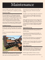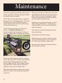
1
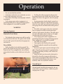
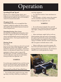
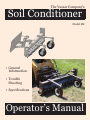
The Vassar Company’s
Soil Conditioner
Model 6M
• General
Information
• Trouble
Shooting
• Specifications
Operator’s Manual
Table of Contents
Specifications...................................................................................................................... 2
Owner Assistance............................................................................................................... 3
General Information.......................................................................................................... 3
Safety Rules......................................................................................................................... 4
Safety Decals....................................................................................................................... 7
Operation............................................................................................................................ 8
Trouble Shooting.............................................................................................................. 13
Maintenance...................................................................................................................... 14
Specifications
Raking Width............................................................................................................................................................ 72 Inches
Roller Type.............................................................................................................. Tooth Roller Standard 10.5” Diameter
Roller Angle.............................................................................................................................. 30 Degrees-Both Directions
Weight.......................................................................................................................................................................... 870 Lbs.
2
Owner Assistance
Thank you for your purchase of a Vassar Equipment product. We at Vassar hope you are fully satisfied and happy
with this piece of machinery and it satisfies all of your needs. If there are any questions you may have, please contact the dealer you purchased the equipment from.
If you did not purchase your Soil Conditioner from a licensed Vassar dealer, please contact the one nearest you
for parts assistance or customer service.
The Vassar Company
1009 West Knipe Avenue
Perkins, OK 74059-3860
(405) 547-2454
General Information
The purpose of this owner’s manual is to educate and inform you about your machine. It also provides information on maintenance and care of the Soil Conditioner. If performed correctly, this machine will help assist you in
all of your landscaping and construction needs with ease. These instructions have been compiled by the senior
design team at Oklahoma State University. The data collected and experience has come from engineers and communication and business professionals.
Illustrations and drawings in this manual were current at time of printing. Models and designs may have
changed from time of printing to your purchase. We reserve the right to redesign and change without consent or
notification.
3
Safety Rules
Safety is a primary concern in the design and
manufacture of our products. Unfortunately, our
efforts to provide safe equipment can be wiped
out by a single careless act of an operator. In addition to the design and configuration of equipment, hazard control and accident prevention are
dependant upon the awareness, concern, prudence, and proper training of personnel involved
in the operation, transport, maintenance, and
storage of equipment.
The design and tested safety of this equipment
depends on it being operated within the limitations as explained in this manual.
Training
• Safety instructions are important. Read all
attachment and power units manuals; follow all
safety decal information. Failure to follow instructions may result in serious injury or even
death
• If you do not understand any part of this manual and need assistance, see your dealer.
• Know your controls and how to stop engine
and attachment quickly in an emergency.
• Operators must be instructed in and be capable of the safe operation of the equipment, its
attachments and all its controls. Do not allow
anyone to operate this equipment without the
proper instructions
Attention: Become Alert.
Your Safety is Involved
Awareness
• Keep hands and body away from pressured
lines. Use paper or cardboard, not body parts, to
check for leaks. Wear safety goggles.
• Hydraulic fluid under pressure can easily pen-
etrate skin and will cause serious injury or death.
• Make sure that all operating and service personnel know that in the event hydraulic fluid penetrates skin, it must be surgically removed as soon
as possible by a doctor familiar with this form of
injury, or gangrene, serious injury or death will
result.
CONTACT A PHYSICIAN IMMEDIATELY IF
FLUID ENTERS SKIN OR EYES.
DO NOT DELAY.
• Do not allow children or untrained persons to
operate equipment.
Preparation
• Always check with your skid-steer manual or
dealer for counter weight ballast that may require
for machine stability.
• Air in hydraulic systems can cause erratic
operation and allows loads or equipment components to drop unexpectedly. Before operating
or allowing anyone to approach the equipment,
purge any air in the system by operating all hydraulic functions several times after connecting
equipment, connecting hoses, or doing any hydraulic maintenance.
• After connecting hydraulic hoses, check that
all control lever positions function as instructed
in the operator’s manual. Do not operate until
control lever and equipment movements are correct.
• Make sure all hydraulic hoses, fittings, and
valves are in good condition and not leaking
before starting power unit or using equipment.
Check and route hoses carefully to prevent damage. Hoses must not be twisted, bent sharply,
kinked, frayed, pinched, or come into contact
4
Safety Rules
with any moving parts. Operate moveable components through full operational range to check
clearances. Replace any damaged hoses immediately.
• Always wear relatively tight and belted clothing to avoid entanglement in moving parts. Wear
sturdy, rough-soled work shoes and protective
equipment for eyes, hair, hands, hearing and
head.
• Ensure implement is properly attached, adjusted and in good operating condition.
Operational Safety
Improper operation can cause the machine to tip
or roll over and cause injury or death.
• Keep skid-steer lift arms and attachment as
low as possible
• Do not travel or turn with skid-steer lift arms
and attachment raised
• Turn on level ground
• Go up and down slopes, not across them
• Keep the heavy end of the machine uphill
• Do not overload the machine
Never use the skid-steer attachment to carry loads
that exceed skid-steer rated operating capacity or
other skid-steer specifications. Check your skidsteer manual or with your dealer for skid-steer
rated operating capacity. Exceeding this capacity
can cause machine to tip or roll over and cause
injury or death.
• Use of a front safety door on the skid-steer is
recommended for operation of the Vassar Soil
Conditioner.
• Do not allow other people in the area when
operating, attaching, removing, and assembling
or servicing equipment.
• Only engage power when equipment is at
ground operating level. Always disengage power
when equipment is raised off the ground.
• Do not disconnect hydraulic lines until all
system pressure is relieved. Lower unit to ground,
stop engine, and operate all hydraulic control
levers.
• Keep bystanders away from equipment while
it is in operation.
Never go underneath equipment lowered to the
ground or raised. Never place any part of the
body underneath equipment or between moveable parts even when the engine has been turned
off. Hydraulic system leak down, hydraulic system failures, mechanical failures or movement of
control levers can cause severe injury or death.
• Service work does not require going underneath the attachment.
• Read operator’s manual for service instructions or have done by a qualified dealer.
• Never direct discharge toward people, animals
or property.
• Do not operate equipment while under the
influence of alcohol or drugs.
• Operate only in the day light or good, artificial
light.
• Keep hands, feet, hair and clothing away from
equipment while engine is running. Stay clear of
all moving parts.
• Always comply with all state and local lighting
and marking requirements.
• Do not allow riders. Do not lift or carry anybody on the skid-steer or attachments.
• Always sit in skid-steer seat when operating
controls or starting engine. Securely fasten seat
belt/operator restraint, place transmission in
park or neutral, engage break and ensure all other
controls are disengaged before starting skid-steer
engine.
Safety Rules
• Look down and to the rear and make sure area
is clear before operating in reverse.
• Use extreme care when working close to
fences, ditches, other obstructions, or on hillsides.
• Do not operate on steep slopes.
• Do not stop, start, or change directions suddenly on slopes.
• Use extreme care and reduce ground speed on
slopes and rough terrain.
• Watch for hidden hazards on the terrain during operation.
• Stop skid-steer and implement immediately
upon striking obstruction. Dismount skid-steer
using proper procedure. Inspect and repair and
damage before resuming operation.
• Before leaving skid-steer steer operator’s seat,
follow skid-steer manual instructions. Lower
skid-steer lift arms and put attachment on the
ground. Stop engine, remove key, brake and remove seat belt/operator restraint.
Maintenance Safety
gine running.
• Keep all persons away from operator control
area while performing adjustments, service or
maintenance.
• Tighten all bolts, nuts, screws and check that
all cotter pins are installed securely to ensure
equipment is in safe condition before operating.
• Ensure all safety decals are installed. Replace if
damaged.
• Ensure shields and guards are properly installed and in good condition.
Storage
• Follow manual for storage.
• Keep children and bystanders away from storage area.
Notes
Your dealer can supply original equipment hydraulic accessories and repair parts. Substitute
parts may not meet original equipment specifications and may be dangerous.
• Avoid electrical system hazards. Never work
on the electrical system unless you are qualified and thoroughly familiar with system details
and the special handling requirements. Disconnect battery before working on electrical system.
Remove “ground” cable first. When reconnecting
battery, connect “ground” cable last.
• Ensure implement is properly attached, adjusted and in good operating condition. Skidsteer coupler lock pins must be fully extended and
properly engaged into attachment retaining slots.
Never perform service or maintenance with en6
Safety Decals
!WARNING!
Do not allow anyone to operate the Soil Conditioner or skid-steer who has nor been properly
trained in it’s safe operation and has not read
and understood the operator’s manuals.
Before attaching implement, check skid-steer
loader lift capacity to ensure its ability to safely
handle the weight.
Do not operate without guards/shields in place
and in good working order.
Stop all moving parts including skid-steer
engine before cleaning, unplugging, adjusting
and/or performing maintenance.
Keep bystanders at least 10 feet away from the
Soil Conditioner when in operation.
Failure to follow the above safety suggestions
and those in the operator’s manual can result in
serious injury or death.
Operation
Safety is a primary concern in the design and
manufacture of our products. Unfortunately, our
efforts to provide safe equipment can be wiped
out by a single careless act of an operator.
In addition to the design and configuration of
equipment, hazard control and accident prevention are dependent upon the awareness, concern,
prudence, and proper training of personnel involved in the operation, transport, maintenance,
and storage of equipment.
It has been said, “The best safety device is an
informed, careful operator.” We ask you to be that
kind of an operator.
The operator is responsible for the safe operation of this equipment. Operators must be instructed in and be capable of the safe operation of
the equipment, its attachments, and all controls.
Do not allow anyone to operate this equipment
without proper instructions.
The 6M Vassar Soil Conditioner is designed
for removing rock and small debris, and for
thatching. Skid-steers must be equipped with an
auxiliary hydraulic system capable of supplying
continuous flow for hydraulic motor operation.
This manual contains information for the 6M
angling model. Refer to the information in this
manual for specifications, parts, assemblies, and
adjustments.
WARNING
• Safety instructions are important! Read all
attachment and power unit manuals; follow all
safety rules and safety decal information. Failure
to follow instructions or safety rules can result in
serious injury or death.
• Do not allow children or untrained persons to
operate equipment.
• Skid-steer must be equipped with ROPS and
seat belt/operator restraint. Keep seat belt/operator restraint securely fastened/engaged. Falling off
skid-steer can result in death from being run over
or crushed. Keep ROPS systems in place at all
times.
• Do not allow other people in the area when
operating, attaching, removing, assembling, or
servicing equipment.
• Never go underneath equipment lowered to
the ground or raised. Never place any part of the
body underneath equipment or between moveable parts even when the engine has been turned
off. Hydraulic system leak down, hydraulic system
failures, mechanical failures, or movement of control levers can cause equipment to drop or rotate
unexpectedly and cause severe injury or death.
• Service work does not require going underneath.
• Read Operator’s Manual for service instructions or have done by a qualified dealer.
• Before leaving skid-steer operator’s seat, follow
skid-steer manual instructions. Lower skid-steer
lift arms and put attachment on the ground. Stop
engine, remove key, engage brake, and remove
seat belt/operator restraint.
ATTACHING POWER RAKE
TO SKID-STEER
• Read the skid-steer Operator’s Manual connecting and removing instruction.
• Position hydraulic hoses so they will not be
pinched when connecting the power rake.
• Move to the skid-steer operator seat and start
engine.
• Lower skid-steer lift arms to their lowest position.
• Carefully move and align the skid-steer to the
power rake. The top of the skid-steer coupler must
index into the power rake flange.
8
Operation
• Roll the skid-steer coupler into the power rake
so the coupler handles can be engaged.
• Shut off the engine, set brake, and remove key.
Dismount the skid-steer.
• Move the skid-steer coupler handles to the
locked position. The lock pins must be completely
extended and secured into the slots provided on
the power rake.
• Connect hydraulic hoses to skid-steer auxiliary quick couplers.
• For hydraulic angling models, mount the angle
control switch in a convenient, easy-to-reach
location. The switch bracket is magnetic and will
attach to any flat steel surface. Connect the power
cord to the cable coming from the switch. Be
careful when routing the cable that sharp edges or
moving parts will not damage the cable.
POWER RAKE FUNCTION
• The power rake hydraulic motor drives the
roller, which digs into the ground, cultivating and
pulling up rocks, roots, and debris.
• The clean soil goes between the roller and barrier, while the rocks, roots, and debris work to the
side in a windrow.
PRE-OPERATION CHECK LIST
(OWNER’S RESPONSIBILITY)
• Review and follow all safety rules and safety
decal instructions on page 7.
• Check that all safety decals are installed and in
good condition. Replace if damaged.
• Check that all shields and guards are properly
installed and in good condition. Replace if damaged.
• Check that all hardware and cotter pins are
properly installed and secured.
• Check that equipment is properly and securely
attached to skid-steer.
• Do not allow riders.
• Check and keep all bystanders away from
equipment working area.
• Check and grease both bearings as instructed
in the maintenance section.
• Check that all hydraulic hoses and fittings are
in good condition and not leaking before starting
skid-steer. Check that hoses are not twisted, bent
sharply, kinked, frayed, or pulled tight. Replace
any damaged hoses immediately.
OPERATING INSTRUCTIONS
Read and understand the power rake and skidsteer Operator’s Manuals before operating the
power rake. Failure to do so may result in death,
serious personal injury, or property damage.
Never raise the power rake more than a few
inches off the ground when traveling from job site
to job site.
• Lower the attachment before shut off.
• Shut off the engine, set brake, remove key,
remove seat belt, and release operator restraint.
• Dismount the skid-steer.
WARNING
• Improper operation can cause the machine to
tip or roll over and cause injury or death.
• Keep skid-steer lift arms and attachment as
low as possible.
• Do not travel or turn with skid-steer lift arms
and attachment raised.
• Turn on level ground.
• Go up and down slopes, not across them.
• Keep the heavy end of the machine uphill.
Operation
• Do not overload the machine.
• Look down and to the rear and make sure area
is clear before operating in reverse.
• Never direct discharge toward people, animals,
or property.
• Only engage power when equipment is at
ground operating level. Always disengage power
when equipment is raised off the ground.
WARNING
Start-up Sequence
Hydraulic Drive Motor
• The hydraulic drive motor runs off the auxiliary circuit of the skid-steer. The power rake should
be run at 30% power for one hour for proper motor break-in.
Power Roller
• Roller should be level with the ground. The
power rake should also be level with the ground
front to back. To accomplish this, raise or lower
gauge wheels and/or use the skid-steer’s tilt cylinder.
• To allow the roller to penetrate deeper into
the ground, loosen the handle and raise the gauge
wheels. To achieve the opposite, lower the gauge
wheels.
• During operation, further depth control can
be achieved by tilting the rake forward on gauge
wheels to raise roller, or by tilting the rake back to
raise gauge wheels and allow more roller penetration.
• The roller on the power rake is hi-rotational.
You can operate the roller in both directions –
clockwise and counter-clockwise. The roller operates most efficiently when it rotates in the opposite direction of the skid-steer wheels.
• Only engage power when equipment is at
ground operating level. Always disengage power
when equipment is raised off the ground.
• Start skid-steer engine.
• Lower power rake slowly to the ground.
• Engage hydraulic control lever for auxiliary
implements.
• Increase engine rpm to give desired rpm at the
roller. Normal operating speed is approximately
270 rpm. If operating in heavy rock, reduce the
speed slightly.
• Move the skid-steer forward or backward as
desired. For the roller to operate effectively, it
must rotate in the opposite direction of the skidsteer wheels. Roller rotation direction is controlled by skid-steer hydraulic controls.
Ground Speed
Ground speed should be determined by the operator. Each scenario will have a different speed
ranging from 2-5 mph.
10
Operation
Operating Depth –Fixed
• When power raking, the depth will determine
how much dirt is carried ahead of the roller. The
ideal depth will vary with conditions and can be
anywhere from skimming the surface to about 3”
deep. See instructions in Power Roller above to set
roller depth.
• When making the first windrow (angling
model only), the level of dirt may be halfway up
on the barrier. When moving the windrow two or
three times, the level of the dirt may be to the top
of the barrier. However, try to prevent material
from flowing over the top.
• The power rake allows fast raking of large
areas of ground by being able to move windrows
several times. Of course, the volume or density of
the material being raked will dictate how many
times a windrow can be moved.
Operator Production
Successful operation of the power rake will come
with operator experience. The rake’s performance
also depends on the type and size of the skid-steer
it’s mounted on.
An operator that masters the technique of adjusting the angle of attack of the roller against the soil
will also find ideal settings under various conditions to give the desired results.
IMPORTANT
• Do not drop power rake to the ground with
the roller turning. Sudden high speed jolts multiply stress to the driveline and can cause extreme
damage.
Parallel Arms (Float Model Only)
The function of the parallel arms is to allow the
power rake to “float” and follow the contour of the
ground.
Application Techniques
The power rake is capable of many applications.
The following are some of the common applications:
Pulverizing Topsoil
For breaking up compacted soil or conditioning hardened baseball diamonds, the attachment
plate is rolled back to take the guide wheels off
the ground so only the toothed roller is in contact
with the ground. Maintain sufficient rpm to avoid
stalling the toothed roller in its progress. The rake
can be straight or angled, but the endplates should
not be mounted in order to allow material to
move out of the way and not slow the process.
Debris Removal
Once the surface has been loosened, the process
of removing debris can begin. The skid-steer attachment plate is tilted forward until the guide
wheels control the depth of the toothed roller. The
roller can be angled at this time for windrowing
debris or the roller can be set straight with both
endplates installed to collect debris. Skid-steer
travel speed should be increased for this process.
Finish Grading
The rake is tilted forward until the teeth of the
toothed roller are barely touching the soil. Skidsteer speed can be increased for this operation,
the idea being to collect material from the high
spots and leave it in the low areas.
11
Operation
Spreading Fill and Topsoil
Position so it is tilted on gauge wheels, since
depth of cut is not the objective. End plates can be
installed and the windrow angle set as needed to
control the material movement.
Changing Grade
Grade modification can be accomplished during finish grading by angling the rake to collect
and windrow the maximum amount of material
toward targeted areas.
servicing equipment.
• On a hard level surface, lower attachment to
the ground.
• Shut off engine, set brake, remove key, remove
seat belt, and release operator restraint before
leaving the skid-steer operator’s seat.
WARNING
Thatching Existing Grass Areas
• Do not disconnect hydraulic lines until all
system pressure is relieved. Lower unit to ground,
stop engine, and operate all hydraulic control
levers.
Shutting Down
• Move attachment coupler latches to the unlocked position (lock pins must be disengaged).
Disconnect hydraulic hoses from quick couplers.
Install dust plugs and couple hoses together for
storage. Disconnect direction control switch from
skid-steer power cord and remove switch.
The skid-steer attachment plate should be tilted
forward to support the rake on the front gauge
wheels and toothed roller raised so teeth are just
grazing the surface. Travel speed should be slow
and careful.
Stop engine.
Lower the lift arms and power rake to the ground.
Purge any air in the system. Hydraulic system
leak down, hydraulic system failures, mechanical
failures, or movement of control levers can cause
equipment to drop or rotate unexpectedly.
Shut off engine, set brake, remove key, remove
seat belt, and release operator restraint before
leaving the skid-steer operator’s seat.
• Move to skid-steer seat and start engine. Release brake and roll attachment coupler until it is
disengaged from the attachment. The attachment
should rest in a stable position for storage.
WARNING
Do not disconnect hydraulic lines until all system
pressure is relieved. Lower unit to ground, stop
engine, and operate all hydraulic control levers.
Removing Power Break From Skid-Steer
• Do not allow other people in the area when
operating, attaching, removing, assembling, or
12
Trouble Shooting
Problem
Possible Cause
Roller Will Not Turn
Hydraulic valve on skid-steer
not engaged
Relief valve setting on skidsteer not properly adjusted
Worn, damaged, insufficient,
or inadequate pump
Insufficient oil in pump
Hose ends not completely
engaged
Air in hydraulic lines
Obstruction in hydraulic lines
Obstruction between roller
and barrier
Chain off
Oil Leaks
Worn or damaged seal
Loose or damaged hoses
Loose or damaged connections
Worn or damaged housing
Roller out of position
Solution
See skid-steer operator’s manual for
auxiliary hydraulic operation procedure.
Have skid-steer dealer set relief valve at
correct pressure.
Repair or replace hydraulic pump.
Service the skid-steer hydraulic reservoir.
Check hose coupling and engage properly.
Cycle skid-steer auxiliary system several times to remove air from lines.
Replace obstructed or damaged line.
Reverse roller to clear obstruction.
Repair or replace chain.
Replace leaking seal.
Replace damaged hoses and secure
loose hoses.
Replace damaged hose connections and
tighten loose fittings.
Replace damaged housing.
Loosen bearing collar on frame and
chain case. Force Roller towards chain,
then tighten bearing collars on chain
and frame.
13
Maintenance
The information in this section is written for dealer
service personnel. The repair described herein
requires special skills and tools. If your shop is not
properly trained in this type of repair, you may be
time and money ahead to replace complete assemblies.
WARNING
• Never go underneath equipment lowered to
the ground or raised. Never place any part of the
body underneath equipment or between moveable parts even when the engine has been turned
off. Hydraulic system leak down, hydraulic system
failures, mechanical failures, or movement of control levers can cause equipment to drop or rotate
unexpectedly and cause severe injury or death.
• Service work does not require going underneath.
• Read Operator’s Manual for service instructions or have done by a qualified dealer.
CAUTION
• Always wear relatively tight and belted clothing to avoid entanglement in moving parts. Wear
sturdy, rough-soled work shoes and protective
equipment for eyes, hair, hands, hearing, and
head.
• Do not allow other people in the area when
operating, attaching, removing, assembling, or
servicing equipment.
• Do not modify or alter, or permit anyone else
to modify or alter, the equipment or any of its
components in any way.
• Do not disconnect hydraulic lines until all
system pressure is relieved. Lower unit to ground,
stop engine, and operate all hydraulic control
levers.
• Ensure implement is properly attached, adjusted, and in good operating condition.
• Ensure all safety decals are installed. Replace if
damaged. (See Safety Decals section for location.)
• Ensure shields and guards are properly installed and in good condition. Replace if damaged.
Hydraulic Motor
Removal
Remove chain from top sprocket. Then remove
top sprocket by removing the hex bolt and washers.
Reassembly
Apply a liberal amount of silicone sealer to inside
of flange. Attach hydraulic motor to chain case
with two bolts and flange nuts. Replace shaft collar. Slide top sprocket, sprocket teeth first, onto
shaft. Use machine bushings on the inside or outside of sprocket for proper alignment.
Bearings
Highest quality bearings are used on the power
rake. Only triple-seal bearings are used on the
roller which operates down in the dirt. Lubrication of bearings will vary considerably with
conditions. As a rule, bearings should be underlubricated rather than over-lubricated. Over-lubrication can cause seals to blow out.
IMPORTANT
• Replacement bearings should be only high
quality original equipment bearings for longer
life.
Install new complete bearing housing if needed or
just replace the bearing insert.
The shafts should be straight, free of burrs, and up
14
Maintenance
to size. If shaft is worn, replace or have the shaft
built up to standard prior to completing assembly.
Protective Collars
The special protective collars protect bearings
from vine and wire wrap, and dirt buildup next
to the bearing seal. The bearing protector is sandwiched onto the shaft which rotates within a close
clearance from the outer race of the bearing.
Grease coming from the bearing oozes into the
protecting collar, keeping dust and particles from
entering the seal area, increasing the bearing life.
Left Roller Bearing
Remove drive chain. Then remove lower sprocket
by removing cotter pin, slotted hex nut, and washers.
Remove the four bolts holding the chain case to
the frame.
Loosen bolt on the bearing tube that holds cartridge bearing in place. Remove bearing and
O-ring.
To replace, reverse the procedure. Be sure all parts
and wear surfaces are thoroughly clean and in
good condition. Be sure O-ring is also in good
condition.
When replacing bearing, first put O-ring on bearing. Apply a coat of grease on O-ring. Slide bearing in and apply moderate pressure on bearing so
O-ring will seat and spread slightly, thus keeping
the oil in chain case from escaping through the
bearing.
Right Roller Bearing
Remove the hex bolt and bearing cap from outside of bearing.
Loosen bolt on the bearing tube that holds cartridge bearing in place. Pry bearing tube apart to
free bearing assembly.
NOTE: Have roller blocked up or supported. Pry
bearing off of shaft and out of bearing holder.
To replace, reverse the procedure. Be sure all parts
and wear surfaces are thoroughly clean and in
good condition.
Roller Replacement
Maintenance
NOTE: Have roller blocked up or supported and
slide chain case and bearing off roller shaft.
It will be necessary to have a lifting device or additional help while removing and replacing the
roller. The roller weighs approximately 150 lbs.
Remove upper and lower chain case covers.
Remove tension spring and drive chain. Then re-
15
Maintenance
move lower sprocket by removing cotter pin, slotted nut, and washers. Remove the spacers behind
the sprocket you just removed.
NOTE: Have the roller blocked up or supported.
Remove the two bolts holding chain case to frame
and slide chain case, with hydraulic motor attached, off of the roller shaft. The roller bearing
will stay in the chain case.
NOTE: If chain case bearing is also being replaced, see Left Roller Bearing above.
Loosen the bolt on the bearing tube of the nondrive end, sliding roller and bearing out of frame.
Place spacers, protective collar, and O-ring from
splined end of removed roller onto replacement
roller. Check O-ring for cuts and nicks. Apply
sealant to bearing area of shaft. Slide chain case
back onto roller and bolt to frame.
Replace spacers, sprocket, and washers on driveshaft. Clamp solid with the 1” slotted jam nut.
Check that roller clears the frame on both ends.
Adjust if required.
Now, tighten 3/8” bolt in bearing tube on nondrive end of frame.
Reinstall chain and tension spring.
Replace lower cover, being careful not to pinch
the O-ring. Fill the chain case with I .5 pints of
85- 140 wt. gear oil. Replace upper cover.
Run power rake and watch for any interference
between roller and frame.
Remove hex bolt, bearing cap, bearing, and protective collar from roller. On roller to be installed,
place machine bushing and protective collar
against endplate of roller. Place bearing and bearing cap on roller. Clamp in place with hex bolt
and lock-washer into end of roller shaft.
Slide roller and bearing into bearing tube on nondrive end of frame . Do not tighten bearing tube
at this time.
16
Notes
17