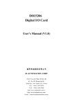
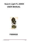
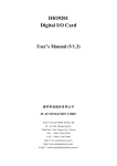
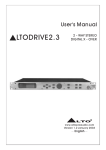
1
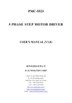
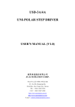
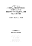
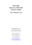
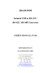
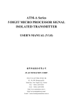
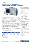
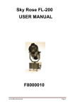
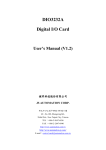
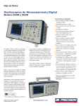
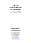
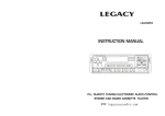
PMC-2520B/2540B/2550B
Step Motor Driver
User's Manual (V1.1)
健昇科技股份有限公司
JS AUTOMATION CORP.
新北市汐止區中興路 100 號 6 樓
6F., No.100, Zhongxing Rd.,
Xizhi Dist., New Taipei City, Taiwan
TEL:+886-2-2647-6936
FAX:+886-2-2647-6940
http://www.automation.com.tw
http://www.automation-js.com/
E-mail:[email protected]
Correction record
Version
1.1
Record
Add PMC2550B
1
Contents
1
Features...............................................................................................................................................3
2
Specifications......................................................................................................................................3
3
I/O Functions......................................................................................................................................4
4
LED indicator.....................................................................................................................................5
5
Control signal .....................................................................................................................................5
6
Wiring diagrams ................................................................................................................................6
7
Dimension ...........................................................................................................................................7
2
1 Features
1.1
1.2
1.3
1.4
1.5
High torque and heavy load design
PWM constant current source
Full/ Half step selection
Build in overheat protection
Build in auto power down mode
2 Specifications
Model
Driving Mode
PMC-2520B
PMC-2540B
PMC-2550B
PWM Switching, Bipolar with Constant Current Driving
2A/Phase
Maximum Current
4A/Phase
5A/Phase
Resolution
Full Step : 1.8o /per step, Half Step : 0.9 o /per step
Input Signal
Optically isolated, Voltage : H : +4V ~ + 24V, L : +0 ~ +5V.
Resistance 220Ω, Current Under 20mA.
CW and CCW Pulse Signal : Pulse Width : Above 5µSec.
Direction Signal : LOW for CW, HIGH for CCW.
Holding Current OFF Signal : HIGH for Release Holding.
Output Signal
Photo-Coupler Open Collector.
Voltage : Under 24V, Current : Under 15mA.
Step 0 Signal
Overheat Signal
DIP Selectors
Auto-Current-Down
Auto-Over-Heat Protection
1P / 2P signal Input Method Selector
Full/Half Step Selector
LED Indicators
Step 0 Status LED
Over-Heat Alarm LED
Power LED
Operation Temperature 0 ~ 45℃
Operation Humidity
< 85% RH
Power source
110 VAC ±10%, 60Hz
Dimension
158mm(L) x 130mm(W) x 52mm(H)
Weight
770g
3
3 I/O Functions
DIP Selectors
Current Selectors
1- frame ground
2- 110V AC power inputr
3- output to step motor
4- over heat signal out
5- STEP0(excitation phase 0) signal out
6- input of Holding Current Off
7- CCW/DIR input
‧CCW for dual pulse mode
‧DIR for single pulse mode
8- CW/PLS input
‧CW for dual pulse mode
‧PLS for single pulse mode
9- User option mode
‧ACD, auto current down
Auto current down while no pulse in. Use this function to reduce the heat of step motor, but if you need
to hold the torque while stand by , switch off to disable this function
‧AOH, auto overheat protection
Switch on to enable the auto overheat protection. While the driver case reaches 80 degree
C, the AOH circuit will stop the driver and activate the AOH led.
‧1P /2P mode
‧1P mode: Pulse (PLS) and direction (DIR) controls the motion operation.
‧2P mode: Clockwise(CW) and counter- clockwise(CCW) controls the motion operation.
‧FULL/HALF step mode
‧FULL step: 1.8 degree per step
‧HASLF step : 0.9degree per step
10- STOP current adjustment
Only valid for ACD is enabled. While ACD function enabled and the pulse train is stopped for
more than 0.5s, the motor current will decrease to the adjustment value.
11- RUN current adjustment
Motor current while running.
4
4 LED indicator
4.1
4.2
4.3
POWER: green LED, power OK will light.
O.H.: red LED, light for over heat while AOH is enabled.
STEP 0: yellow LED, light for excitation phase 0, in full step mode, it will light every 4 steps
and for half step mode every 8 steps.
5 Control signal
5.1
5.2
5.3
5.4
The control signal is isolated by photo-isolator and the external signal transit state from HIGH
to LOW will drive one step.
The minimum pulse width is 5 micro second, the transition time is less than2 micro second.
The input voltage range is from 5VDC to 24VDC and the current must limit to under 20ma.
The driver output signal is limited to under 15ma.
Input Signal circuit
Pulse Width Diagram
Output Signal circuit
5
6 Wiring diagrams
6.1
4 Leads
*NC = Not connected to anything
4 Leads
6.2
6 Leads
*NC = Not connected to anything
6 Leads
Series Connected
6.3
6 Leads
Center Tap Connected
8 Leads
*NC = Not connected to anything
8 Leads
Series Connected
8 Leads
Parallel Connected
Notes on wiring:
*Be sure to power off while motor is being wired.
*Wrong wiring or wire may damage the driver.
*The external force cooling is required, if you the driver case temperature is higher than 55 degree C
at normal operation.
*Please use the driver at good ventilation environment.
*Please do not use the driver at wet or the environment may have condensed water.
6
7 Dimension
Approx. Current Adjustment and Auto current down % List
Ø
2520B
2540B
ACD%
0
0.23A
0.56A
015%
1
0.26A
0.70A
021%
2
0.40A
0.90A
026%
3
0.50A
1.20A
032%
4
0.66A
1.40A
038%
5
0.80A
1.52A
043%
6
0.89A
1.66A
049%
7
1.05A
1.86A
055%
8
1.10A
2.10A
060%
9
1.31A
2.32A
066%
A
1.43A
2.54A
071%
B
1.61A
2.80A
077%
C
1.73A
3.10A
083%
D
1.86A
3.40A
088%
E
2.00A
3.70A
094%
F
2.14A
4.00A
100%
7