1
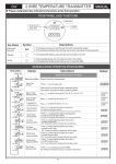
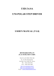
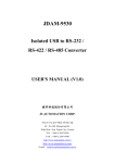
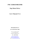
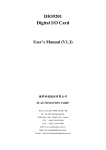
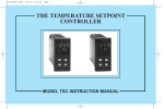
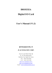
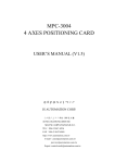
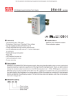
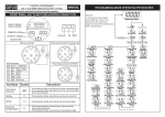
ATM-A Series
5 DIGIT MICRO PROCESSOR SIGNAL
ISOLATED TRANSMITTER
USER'S MANUAL (V1.0)
健昇科技股份有限公司
JS AUTOMATION CORP.
新北市汐止區中興路 100 號 6 樓
6F., No.100, Zhongxing Rd.,
Xizhi Dist., New Taipei City, Taiwan
TEL:+886-2-2647-6936
FAX:+886-2-2647-6940
http://www.automation.com.tw
http://www.automation-js.com/
E-mail:[email protected]
Contents
1.
2.
3.
4.
5.
6.
7.
8.
9.
10.
Features ......................................................................................................................................... 2
Specifications................................................................................................................................ 2
Front panel & Key functions......................................................................................................... 3
General Mode Operating Procedures............................................................................................ 4
Programming Mode Operating Procedures .................................................................................. 5
Error Code of Self-Diagnosis........................................................................................................ 6
Calibration Operating Procedures................................................................................................. 6
Dimensions ................................................................................................................................... 7
Wiring Connection ........................................................................................................................ 8
Ordering information …………………………………………………………………………..9
1
1. Features
Versatile Input selection : DC / AC / PT-100 / Potentiometer / Resistor / Load Cell
Versatile output selection : 4~20mA , 0~20mA , 0~5V , 0~10V
Accuracy: ±0.1%
F.S. (Others) ; ±0.2%
F.S. (AC)
Surge test of AC 2000V/ 1min between input / output / power
High stability, non-flammable case (PC), high safety
2. Specifications
Input selection : DC / AC / PT-100 / Potentiometer / Resistor / Load Cell
Output selection : 4~20mA ,0~20mA ,0~5V ,0~10V
Accuracy : ±0.1% F.S. (Others)
±0.2% F.S. (AC)
Display Screen : High brightness red LED; 10.16mm(0.4")
Display Range : -19999~99999
Zero Adjustment : ±9999 ; Span Adjustment : ±9999
Parameters Setting : Push buttons
Back Up Memory : EEPROM
Over Range Indication : doFL/ioFL or -doFL/-ioFL
Analog Output Resolution : 15 bit
Output Ripple : ≦±0.1% F.S.
Output Response Time : <250 msec (0~90%)
Output Capability : Voltage Output: <20Ma
Current Output: <10V
Isolation : Input / Output / Power / Case
Insulation Resistance : >100MΩ with 500Vdc
Surge Test : 2KVac/1min
Input Impendence : Current: ≧0.2A at 100mV; <0.2A at 1V
Voltage: >2V for 20KΩ/V; ≦2V for >200MΩ
Temperature Coefficient :100ppm/degree C (0~60 degree C )
Operating Temperature : 0-60 degree C
Operating Humidity : 20 to 90% RH (non-condensing)
Storage Temperature : -10-70 degree C
Storage Humidity : 20 to 90% RH (non-condensing)
Power Supply : AC 110, AC 220V
Installation : Socket / Plug-in
2
3. Front panel & Key functions
Key Name
Reset Key
Enter Key &
Save Key
Shift Key
Up Key &
Display Value
Adjusting Key
Down Key &
A/O Adjusting
Key
Symbol
Descriptions
1. Press this key to enable the reset function & reset indicator (Z) is light;
press this key again to disable the reset function & reset indicator (Z) is dark.
1. In the measuring status, press this key can enter to parameter pages.
2. In the parameter setting, press this key can save the value & go to next page.
1. In the parameter setting , press this key can move the cursor left.
1. In the measuring status, press this key for 3 sec can enter to display
adjustment of "ZERO" & "SPAN"
2. In the parameter setting, press this key can increase the digits.
1. In the measuring status, press this key for 3 sec can enter to analog output
adjustment.
2. In the parameter setting , press this key can decrease the digits.
1. The following block charts are parameters codes, parameter codes & parameters will alternate
flashing if the parameters can be modified.
2. To modify the parameters, please press
, and press ENT to save the parameters after the
modification.
3. Please don't forget the new pass code after modification.
4. In any pages, pres & , or don't press any keys for 2 minutes that will back to measuring
status.
3
4. General Mode Operating Procedures
Block Charts
Display
Measuring
Status
Display
(dZEro)
Adjustment
(dZEro)
Display Span
Adjustment
(dSPAn)
Measuring
Status
A/O Zero
Adjustment
(AZEro)
A/O Span
Adjustment
(ASPAn)
Descriptions
Display : "ZERO" & "SPAN" Adjustment
Present value for measurement.
Press to select adjusting speed rate, press
to
modify the zero value.
PS: To use this function to adjust the real zero
value.
Press to select adjusting speed rate, press
to
modify the span value.
PS: To use this function to adjust the real span
value.
Analog Output: "ZERO" &"SPAN" Adjustment
Present value for measurement.
Press to select adjusting speed rate, press
to
modify the A/O zero.
PS: To use this function to adjust the real A/O zero.
Press to select adjusting speed rate, press
to
modify the A/O span.
PS: To use this function to adjust the real A/O span.
4
Default
5. Programming Mode Operating Procedures
Block Charts
Display
Descriptions
Measuring Present value for measurement.
Status
Pass Code Press
to enter pass code.
(P.Cod)
Pass code is correct that will enter to parameter groups.
Pass code is wrong that will back to measuring status.
Decimal
Pass
to select decimal point (0, 1, 2, 3, 4).
Point
EX: if the value shows "0.00" that means the decimal
Setting (dP) point is 2 digits.
Display
Pass
to modify display low scale for the input
Low Scale signal zero value.
Setting
EX: If the input signal is 4~20mA; 4mA is shown
(dSPL)
display 0.00, this parameter must be set for 000.00.
Display Hi Pass
to modify display high scale for the input
Scale
signal span value.
Setting
EX: If the input signal is 4~20mA; 20mA is shown
(dSPH)
display 100.00, this parameter must be set for 100.00.
Display
Pass
to modify display average (1~99).
Average
PS: Please use this function for stable display value
Setting
when input signal is unstable.
(AvG)
Display
Pass
to modify display low cut to 0 (0~99).
Low Cut
Setting
(LCUt)
A/O
Pass
to modify output is positive pole or
Polarity
negative pole.
Setting
PS : Voltage output ,NO: positive pole output (0~+10V)
(PoLAr)
YES: positive & negative pole output (-10~+10V)
A/O Low Pass
to adjust A/O low scale to correspond to
Scale
the display value.
Setting
EX : A/O is 0~10V, the display is 10.0 to output 0V, this
(AnLo)
value must be set for 10.0.
A/O Hi
Pass
to adjust A/O hi scale to correspond to the
Scale
display value.
Setting
EX : A/O is 0~10V, the display is 90.0 to output1 0V,
(AnHi)
this value must be set for 90.0.
Pass Code Pass
to modify pass code (0~19999).
Setting
PS: Please don't forget the new pass code after
(CodE)
modification.
Key Lock Pass
to lock the keys, using key lock function only
Setting
can view the parameters, but cannot modify any values.
(LoCK)
PS: no (unlock) ,YES ("ENT" unlock , others lock).
5
Default
Customers
specify
Customers
specify
6. Error Code of Self-Diagnosis
Display
Descriptions
Input signal is over 120% of input range.
Input signal is under
-20% of input range.
Input signal is over 180% of input range or meter error.
Input signal is over display range (99999).
Input signal is under display range (-19999).
EEPROM reading/writing suffers the interference (about 1 million times).
※Please check the wiring connection is correct first, if the problem still exist, please return the meter
to the factory.
7. Calibration Operating Procedures
Display
Descriptions
Default
Measuring Status Present value for measurement
Press ENT & together for 3 sec will enter to
calibration operating procedures.
Input Low Scale 1. Input standard low scale signal.
Calibration (inLo) 2. Press
to calibrate input low scale.
Input Hi Scale
1. Input standard hi scale signal.
Calibration (inHi) 2. Press
to calibrate input hi scale
System Setting
1. Finish calibration operating procedures will enter
Page (SYS)
to system setting group.
2. Press & together to back to measuring status.
Warning: Calibration of this meter requires a standard signal with 0.01% accuracy or better and an
external meter with 0.005% accuracy or better.
6
8. Dimensions
7
9. Wiring Connection
Voltage (V), Current (A)(AC, DC)
4 Wire Sensor or Load cell
Temperature (RTD)
2 Wire Sensor
2 Wire Resistor
3 Wire Sensor
3 Wire Potentiometer
8
10.
Ordering information
1 : 2 wire type offers excitation power DC24V for 2 wire (Loop Power) pressure, temperature,
humidity sensors using.
2 : 3.4 wire type offers excitation power DC24V for 3, 4 wire (Loop Power) pressure,
temperature, humidity sensors using.
9