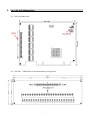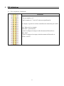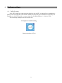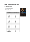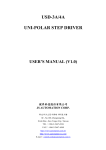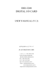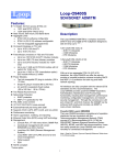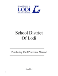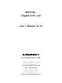
1
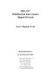
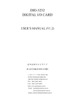
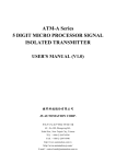
DIO3206
Digital I/O Card
User’s Manual (V1.0)
健昇科技股份有限公司
JS AUTOMATION CORP.
新北市汐止區中興路 100 號 6 樓
6F., No.100, Zhongxing Rd.,
Xizhi Dist., New Taipei City, Taiwan
TEL:+886-2-2647-6936
FAX:+886-2-2647-6940
http://www.automation.com.tw
http://www.automation-js.com/
E-mail:[email protected]
Correction record
Version
Record
1
Contents
1.
Forward ................................................................................................................................................ 4
2.
Features ................................................................................................................................................ 5
2.1
Main card ................................................................................................................................. 5
Specifications ....................................................................................................................................... 6
3.1
DIO3206 Main card ................................................................................................................. 6
3.2
JS51060 60P Din rail mounted dummy wiring board .......................................................... 6
Layout and dimensions ........................................................................................................................ 7
4.1
DIO3206 Main card ................................................................................................................. 7
4.2
JS51060 60PM Din rail mounted dummy wiring board ....................................................... 7
PIN definitions ..................................................................................................................................... 8
5.1
CN1 Assignment / Definitions ................................................................................................. 8
3.
4.
5.
6.
Hardware settings ................................................................................................................................ 9
7.
6.1
CARD ID setting ..................................................................................................................... 9
Ordering information ......................................................................................................................... 10
2
Notes on hardware installation
Please follow step by step as you are installing the control cards.
1. Be sure your system is power off.
2. Be sure your external power supply for the wiring board is power off.
3. Plug your control card in slot, and make sure the golden fingers are put in right contacts.
4. Fasten the screw to fix the card.
5. Connect the cable between the card and wiring board.
6. Connect the external power supply for the wiring board.
7. Recheck everything is OK before system power on.
8. External power on.
Congratulation! You have it.
For more detail of step by step installation guide, please refer the file “installation.pdf “ on the CD
come with the product or register as a member of our user’s club at:
http://automation.com.tw/
to download the complementary documents.
Warning:
Some computer BIOS has “Auto detect DIMM/PCI clock” option, be sure to switch to
“DISABLE” else in some cases the PCI add on cards will not be detected by windows at cold start.
3
1. Forward
Thank you for your selection of DIO3206 6ports (48bits) TTL DIGITAL I/O card for industrial PC.
This card is a FPGA based design and each port is software configurable as input or output. At the
interface, a bus driver chip is adopted to enhance the drive capacity of the output. The bus driver also
protect the FPGA from any damage from instantaneous mal-connection.
Other DIO series products:
DIO9201 16 channel input and 16 channel output isolated digital I/O card (ISA bus)
DIO2232 32 channel input and 32 channel output isolated digital I/O card (ISA bus)
DIO2248 48 channel input and 16 channel output isolated digital I/O card (ISA bus)
DIO2264 64 channel input isolated digital I/O card (ISA bus)
DIO3208B 8 channel input and 8 channel relay output isolated digital I/O card (PCI bus)
DIO3216B 16 channel input and 16 channel output isolated digital I/O card (PCI bus)
DIO3217 16 channel input and 16 channel output isolated digital I/O card (PCI bus)
with multifunction timer/counter
DIO3232 32 channel input and 32 channel output isolated digital I/O card (PCI bus)
DIO3248 48 channel input and 16 channel output isolated digital I/O card (PCI bus)
DIO3264 64 channel input isolated digital I/O card (PCI bus)
DIO4264 64 TTL digital I/O PC-104 Module
DIO6208 8 channel input and 8 channel relay output isolated digital I/O PCI-104 Module
DIO6216 16 channel input and 16 channel relay output isolated digital I/O PCI-104 Module
Any comment is welcome,
please visit our website
http://www.automation.com.tw/
http://www.automation-js.com/ for the up to date information.
4
2. Features
2.1 Main card
2.1.1
48 (6 port) TTL digital I/O channels
2.1.2
Programmable digital filter at 100Hz,200Hz,1KHz and no de-bounce for input
2.1.3
No output transition during start-up
2.1.4
Output status read back
2.1.5
External triggered interrupt (on IN00~IN07)
2.1.6
32-bit timer with cross zero interrupt
5
3. Specifications
3.1 DIO3206 Main card
Input Section
3.1.1
Input : 48(max) TTL level
3.1.2
Interrupt at IN00 ~IN07
Output Section
3.1.3
Output level: 48(max) TTL level
3.1.4
Output source : 35mA(peak) per channel
3.1.5
Output Sink : 35mA(peak) per channel
Main Card General
3.1.6
Card ID : 4 bits
3.1.7
Connector : 60-pin male flat-cable connector
3.1.8
Operation temperature : 0 to +70 degree C
3.1.9
Storage temperature : -20 to +80 degree C
3.1.10 Operation humidity : 5~95% RH, non-condensing
3.1.11 Dimensions : 130(W) * 102(H) mm , 5.2(W) * 4.1(H)in
3.2 JS51060 60P Din rail mounted dummy wiring board
3.2.1
Connection cable ─ 60-pin flat cable to connect main and wiring board
3.2.2
Dimension ─ 86(W)*204(L)*45(H)mm , 3.4(W)*8.1(L)*1.8(H)in
6
4. Layout and dimensions
4.1 DIO3206 Main card
4.2 JS51060 60PM Din rail mounted dummy wiring board
7
5. PIN definitions
5.1 CN1 Assignment / Definitions
Definitions
IOxy
x: the port number, 0~5
y: the bit number, 0~7, the bit7 is the most significant bit
for example, if port2 bit3 will be controlled, the connection pin is IO23
Note: Take port 0 as example,
IO00~IO07 : port0 data bit,
if port0 is configured as input, in this document will describe as
IN00 ~IN07
if port0 is configured as output, in this document will describe as
OUT00 ~OUT07
8
6. Hardware settings
6.1 CARD ID setting
Since PCI cards have plug and play function, the card ID is required for programmer to
identify which card he/she will control without knowing the physical address assigned by the
Windows. A 4-bit DIP switch or rotary switch for distinguishing the 16 identical card.
The following example sets the card ID at 0.
Example for card ID setting
Rotary switch set at ID=0
9
7. Ordering information
PRODUCT
DESCRIPTIONS
DIO3206
48-channel TTL Digital I/O Card
JS51060
DIN rail mounted dummy wiring board (60P Male to terminals)
M23223
60-pin flat cable 1.5 M
M23224
60-pin flat cable 3.0 M
10