1
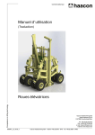
TVE12041
Examensarbete 15 hp
Maj 2012
Measurement system with image
analysis
Detecting signal disturbances in the Head-up
display of the JAS 39 Gripen
Jenny Eriksson
Matilda Dahlqvist
Lars Svensson
Abstract
Measurement system with image analysis
Jenny Eriksson, Matilda Dahlqvist, Lars Svensson
Teknisk- naturvetenskaplig fakultet
UTH-enheten
Besöksadress:
Ångströmlaboratoriet
Lägerhyddsvägen 1
Hus 4, Plan 0
Postadress:
Box 536
751 21 Uppsala
A measurement system has been developed to detect errors in the head-up display of
JAS 39 Gripen. Errors have been identified by continuously capturing images of the
display and comparing it to a reference image. Signal acquisition has been made
concurrently with a Data Acquisition device and the data has been processed and
analyzed in LabVIEW, a visual programming tool.
The resulting measurement system functioned as intended. There was an uncertainty
in the time stamp of the logged error, with a standard deviation of 15.1 ms.
Telefon:
018 – 471 30 03
Telefax:
018 – 471 30 00
Hemsida:
http://www.teknat.uu.se/student
Handledare: Per Nilstad, Mikael Lindeman
Ämnesgranskare: Ken Welch
Examinator: Martin Sjödin
ISSN: 1401-5757, TVE12041
Populärvetenskaplig sammanfattning
Ett mätsystem har tagits fram med syftet att detektera orsaker till
fel i siktlinjesindikatorn, det vill säga siktesanordningen, på JAS 39
Gripen. Fel har identifierats genom att filma displayen kontinuerligt
och jämföra bilderna med en referensbild. Samtidigt har signaldata
från siktlinjesindikatorn insamlats med hjälp av ett Data Acquisitionkort. Dessa data har sparats på fil när den nytagna bilden från en
kamera skiljt sig från referensbilden. Databehandlingen och analysen
har gjorts i LabVIEW som är ett grafiskt programmeringsverktyg.
Det resulterande systemet fungerade som planerat. Det hade en mätosäkerhet
i tiden för ett inträffat fel. Det visade sig att 95 procent av de
uppmätta tiderna skiljde sig med upp till 30.2 millisekunder från den
egentliga tiden.
1
Table of contents
1 Background
1.1 SAAB AB . . . . . . . . . . . . . . . . . . . . . . . . . . . . .
1.2 Head-Up Display . . . . . . . . . . . . . . . . . . . . . . . . .
1.3 Problem description . . . . . . . . . . . . . . . . . . . . . . . .
4
4
4
5
2 Objective
5
3 Theory
3.1 Image Acquisition . . . .
3.2 Image Analysis . . . . .
3.3 Signal Acquisition . . . .
3.4 Software for analysis and
3.5 Signal Conditioning . . .
. . . . . . .
. . . . . . .
. . . . . . .
acquisition
. . . . . . .
4 Method development
4.1 Hardware . . . . . . . . . . . . . .
4.1.1 Camera . . . . . . . . . . .
4.1.2 Expresscard adapter . . . .
4.1.3 Camera attachment solution
4.1.4 DAQ device . . . . . . . . .
4.1.5 Signal conditioning . . . . .
4.1.6 Notebook computer . . . . .
4.2 Software . . . . . . . . . . . . . . .
4.2.1 Programming tools . . . . .
4.2.2 Measurement VI . . . . . .
4.2.3 Presentation VI . . . . . . .
4.3 Signals . . . . . . . . . . . . . . . .
4.4 Testing . . . . . . . . . . . . . . . .
5 Results
5.1 Hardware . . . . . . . . . . .
5.2 Software . . . . . . . . . . . .
5.2.1 Measurement VI GUI .
5.2.2 Presentation VI GUI .
5.3 Testing and time stamp . . .
.
.
.
.
.
.
.
.
.
.
.
.
.
.
.
.
.
.
.
.
.
.
.
.
.
.
.
.
.
.
.
.
.
.
.
.
.
.
.
.
.
.
.
.
.
.
.
.
.
.
.
.
.
.
.
.
.
.
.
.
.
.
.
.
.
.
.
.
.
.
.
.
.
.
.
.
.
.
.
.
.
.
.
.
.
.
.
.
.
.
.
.
.
.
.
.
.
.
.
.
.
.
.
6
6
6
6
6
7
.
.
.
.
.
.
.
.
.
.
.
.
.
.
.
.
.
.
.
.
.
.
.
.
.
.
.
.
.
.
.
.
.
.
.
.
.
.
.
.
.
.
.
.
.
.
.
.
.
.
.
.
.
.
.
.
.
.
.
.
.
.
.
.
.
.
.
.
.
.
.
.
.
.
.
.
.
.
.
.
.
.
.
.
.
.
.
.
.
.
.
.
.
.
.
.
.
.
.
.
.
.
.
.
.
.
.
.
.
.
.
.
.
.
.
.
.
.
.
.
.
.
.
.
.
.
.
.
.
.
.
.
.
.
.
.
.
.
.
.
.
.
.
.
.
.
.
.
.
.
.
.
.
.
.
.
.
.
.
.
.
.
.
.
.
.
.
.
.
.
.
.
.
.
.
.
.
.
.
.
.
.
7
7
8
9
9
9
9
11
11
11
11
14
14
14
.
.
.
.
.
15
16
17
17
19
20
.
.
.
.
.
.
.
.
.
.
.
.
.
.
.
.
.
.
.
.
.
.
.
.
.
.
.
.
.
.
.
.
.
.
.
.
.
.
.
.
.
.
.
.
.
.
.
.
.
.
.
.
.
.
.
.
.
.
.
.
.
.
.
.
.
6 Discussion
21
6.1 Effects of downgrading LabVIEW . . . . . . . . . . . . . . . . 21
6.2 Measurement accuracy . . . . . . . . . . . . . . . . . . . . . . 21
6.3 Processor bottleneck . . . . . . . . . . . . . . . . . . . . . . . 22
2
6.4
6.5
Software Robustness . . . . . . . . . . . . . . . . .
Suggested further development . . . . . . . . . . . .
6.5.1 Exporting a standalone application . . . . .
6.5.2 Acquire more signals . . . . . . . . . . . . .
6.5.3 Increase measurement accuracy and stability
6.5.4 Trigger on a signal error . . . . . . . . . . .
6.5.5 Replacing the camera with a light sensor . .
7 Conclusion
.
.
.
.
.
.
.
.
.
.
.
.
.
.
.
.
.
.
.
.
.
.
.
.
.
.
.
.
.
.
.
.
.
.
.
.
.
.
.
.
.
.
22
23
23
23
24
24
24
25
3
1
1.1
Background
SAAB AB
SAAB AB is an aerospace and defence company that has provided the
Swedish Airforce with military aircraft since it was founded in Trollhättan
1937. The company consists of the five major divisions Support and Services,
Security and Defence Solutions, Aeronautics, Dynamics and Electronic Defence Systems. Aeronautics develop the JAS 39 Gripen system, Dynamics
produce ground combat weapons and Electronic Defence Systems develop
radar systems. Security and Defence Soutions deals with training and simulation and Support and Services provide maintenance, field facilities and
testing equipment for customers. This bachelor thesis work was performed
at the Department Test Solutions under Support and Services at Saab in Arboga. The department mainly deals with development of testing equipment
and repairs of electronic components for the systems in the JAS 39 Gripen.
1.2
Head-Up Display
The head-up display (HUD) is a transparent display located in front of the
pilot, see figure 1. The system consists of a cathode ray tube emitting a light
beam reflected by a system of mirrors and collected by a lens which only
transmitts a narrow frequency band in the green frequency range. The result
is that the pilot sees a hologram of the transmitted image focused about 20
meters in front of the plane. This feature gives the pilot the ability to focus
on both crosshairs and target at the same time and the possibility of altering
the aiming device for different weapon systems.
Figure 1: Position of the Head-Up Display in the cockpit of JAS 39 Gripen
4
1.3
Problem description
The Department of Test Solutions performs repairs of head-up displays that
have shown problems during operation. A problem occurring in several units
is unexpected shutdown during operation making the entire display go black.
This is probably caused by abnormalities in one or more of the system’s input
signals. In the testing facility in Arboga, technicians can simulate a system
failure of this kind in a stationary test rig. However, they currently have no
equipment to accurately correlate the system failiure to a certain set of input
signals. To detect abnormal input signals or loose wiring a custom designed
measurement system is needed.
2
Objective
The project’s main objective was to design a measurement system to aid the
technicians analyzing the signal package going in the head-up display seconds
before and after the disturbance occurs. The specifications of the system are:
• Errors should be identified by analyzing images of the HUD captured
by a camera
• Signal and video data were to be saved from ten seconds before to three
seconds after an error occurred
• The system should be mobile
• The uncertainty in the time stamp should not exceed ten milliseconds
• The system should be able to acquire video data and 16 signals from
the HUD.
• The system should be able to run for up to five hours
• The system must be able to measure signals from the HUD ranging
from -100 to 100 volts
• The software interface should be designed in a user-friendly manner
• An audio alarm should sound when an error has occurred
5
3
Theory
3.1
Image Acquisition
The displayed image of the HUD is drawn line by line on the collimating glas
with a certain update rate.1 To film a continuously updated display with a
digital video camera has complications. A digital video consists of a sequence
of images captured by a sensor. Normal acquisition rate is 25-30 frames per
second but faster cameras are available. If the shutter of the camera is open
for a shorter time than the time it takes for the HUD to draw one display
cycle, the frame is delivered incomplete. In cases when the camera frame rate
is an even multiple of the display update rate, the drawing operation appears
in the same finished or unfinished state in every frame. This problem may
cause the captured video to fade in and out for second-long periods.
3.2
Image Analysis
Image analysis can be made in several ways and the choice of method depends
on the accuracy demands. Each pixel of an image contains information about
color and intensity. To compare two images and decide if they are similar
one can extract and compare data pixel by pixel.
3.3
Signal Acquisition
Data acquisition (DAQ) is a process that samples analog signals and convert
them to digital values for processing in a computer and it is done with a
DAQ device. There are different models of DAQ devices adapted for different
measurement situations. For example, how many and what type of signals
to acquire, the sampling rate and the hardware interface. [1]
3.4
Software for analysis and acquisition
When combining image analysis and signal acquisition it is convenient to
handle them in the same programming tool. One can either use a text-based
or a visual programming language. A text-based programming environment,
for example MATLAB, gives greater scope to accurately shape the program’s
functionality, but it is often more time-consuming to build and less user
friendly. A visual programming tool generally makes the development process
quick and the code easy to understand. This is because it works with blocks of
pre-written code, called Virtual Instruments (VIs), presented as icons instead
1
The update rate is confidential.
6
of rows of text commands. It was decided to use the visual programming tool
LabVIEW, which is frequently used in various types of data acquisition. The
LabVIEW user interface is divided into two parts – one for the code and one
for execution.
3.5
Signal Conditioning
Signal conditioning is necessary if the signals to be measured do not fit the
acquisition device. For example, a noisy signal may have to be filtered to be
able to extract relevant information from it. If a signal has higher voltage
levels than the analog inputs of the DAQ device are specified for it has to
be conditioned. There is a variety of methods to lower the voltage without
losing relevant information from the signal. Voltage division is a method to
linearly lower voltage levels of signals.
Figure 2: Scheme of a voltage divider
The layout of a voltage divider is illustrated in figure 2. In this case the
outgoing voltage is given by equation (1) where Uin and Uout are voltages
and Z1 and Z2 are resistances.
Uout =
4
4.1
Z2
× Uin
Z1 + Z 2
(1)
Method development
Hardware
To troubleshoot the head-up display a customized signal measurement instrument with image analysis was created. The measurement system consisted
7
of three parts: image acquisition and analysis, signal acquisition and presentation of the data. Hardware used in the image analysis was a digital
camera and a DAQ-device for signal acquisition. The measurement system
should be a mobile solution and hardware used for presentation of data and
analysis was therefore a notebook PC. A schematic overview of the system
is displayed in figure 3.
Figure 3: Graphical illustration of measurement system components
4.1.1
Camera
For the image analysis a camera with the right characteristics was needed,
particularly a high frame rate. The most cost efficient camera that was found
had a rate of 120 fps (frames per second). Cameras with a higher frame rate
were available, but they saved the data internally for later exportation. For
this application real time data transfer of every frame was needed.
The captured frames were transferred for analysis in the software. Since
the camera had to be compatible with the software, the best alternatives for
transferring the images with was USB, GigE or IEEE1394B [2].
8
There was a demand on the amount of data transferred each second. A
USB-interface is limited when it comes to high-speed data transfer. Since
GigE is a more expensive solution than IEEE1394B, IEEE1394B was used.
Since slow auto-adjustments in low budget cameras were considered a risk
for the image analysis it was decided to choose a high quality camera. The
chosen camera was Basler scout IEEE1394B Area scan camera scA640-120fc.
It had the frame rate needed, the interface IEEE1394B and also it was recommended by National Instruments, the producer of LabVIEW.
4.1.2
Expresscard adapter
The specified camera frame rate demanded a transfer speed of 800-1000
Mbit/s in the interface between the camera and the notebook computer.
IEEE1394B, also called Firewire 800, was chosen. The notebook computer
did not have an internal IEEE1394B port so to connect the Basler Scout
camera an IEEE1394B Expresscard adapter was used. The Expresscard slot
on modern notebook computers can handle speeds of up to 2500 Mbit/s so
the IEEE1394B interface could be utilized at full speed. Since the express
card slot cannot deliver power to the camera a separate 12V power supply
was utilized.
4.1.3
Camera attachment solution
While the camera recorded images from the head-up display it had to be in
a fixed but adjustable position. The solution was to construct a device with
appearance similar to an already existing attachment solution to the head-up
display. The measurements of the camera were handed over to a prototype
workshop, which constructed the attachment solution.
4.1.4
DAQ device
For acquiring the signals from the Head-Up display a DAQ device was used.
The DAQ device was ordered from National Instrument and was of the model
NI USB-6210. The interface selected was USB, which in this case it did not
limit the data transfer. This model was used to sample 16 channels at a
voltage range of ± 10 V.
4.1.5
Signal conditioning
The signals acquired by the DAQ device had different voltages ranging up
to 100 V. To comply with the specifications for the DAQ device a voltage
9
divider was required for certain channels to lower the voltage levels. The
signals that were conditioned had voltage levels of -100V, 30V and 28V respectively. The layout of the voltage divider is displayed in figure 4. To be
sure not to overload and effect the HUD system with excessive current levels
two resistors in the kΩ range was chosen. The following resistors were used.
Divider 1 for U1 in=28V: Z1 = 68kΩ, Z2 = 13kΩ
Divider 2 for U2 in=30V: Z1 = 68kΩ, Z2 = 13kΩ
Divider 3 for U3 in=100V: Z1 = 68kΩ, Z2 = 4.4kΩ
Figure 4: Layout of the voltage divider
The resistors were soldered to a lab card along with connector cables. A
control measurement of the ratios was conducted to compensate for imperfections of the resistors and inner impedance of the DAQ device.
To ensure durability and facilitate use of the measurement system the DAQ
device and the voltage divider was mounted and enclosed in an aluminum
electronics-box. The box was fitted with cable glands for the outgoing USB
cable and for the signal cable connected to the HUD via a 96-pole DIN 41612
connector.
10
4.1.6
Notebook computer
The computer used was a Dell Latitude E4300 with an Intel Core 2 Duo
P9400, 2.40GHz, 4 Gb RAM and an SSD storage drive. The dual-core processor can manage two separate strings of code simultaneously, provided the
program is adapted for this feature.
4.2
Software
Image analysis, signal saving and presentation of data were accomplished
using LabVIEW. Two different VIs were created, one for the acquisition and
analysis and one for the presentation. They were called Measurement VI and
Presentation VI.
4.2.1
Programming tools
The software used, that was compatible with both the camera and the DAQ
device was LabVIEW. LabVIEW is very user friendly while working with
image- and signal processing. One option was to acquire the signals in LabVIEW and then do the analysis in MATLAB, however, trouble with compatibility was expected. It would be a more expensive solution since some
licenses for extra modules for LabVIEW already existed at SAAB.
The licenses to the vision modules existing at SAAB were however earlier
versions, so they were not compatible with the latest version of LabVIEW
(LabVIEW 2011). The option was either to purchase licenses for the latest
versions of the modules or to downgrade LabVIEW. To upgrade the extra
modules would be an additional investment and therefore it was decided to
downgrade LabVIEW, with the risk of losing some useful functions in the
latest version. A result of the downgrade was that the operating system had
to be downgraded as well from Windows 7 to Windows XP.
The software used for the image analysis was NI LabVIEW 8.6, NI Vision Acquisition 8.6 which enabled acquisition of images and NI Vision Development
Module 8.6 which enabled analysis of the acquired images.
4.2.2
Measurement VI
The Measurement VI created in LabVIEW was based on the idea of comparing the recorded images to an initial reference shot. The intensity from
each frame in the video was compared to the intensity of the reference image. If the difference between the intensity in the frames was below a certain
11
value saving of acquired signal data was initiated. The saved signal data
ranged from ten seconds before to three seconds after the error occurred on
the head-up display. The structure of the VI is shown in figure 5.
Figure 5: Structure of the Measuring VI
The VI started with showing a real time video used to calibrate the camera
position. When the calibration was finished the camera continued capturing
frames, frame number 60 was set to be the reference image (golden picture),
if the user accepted it. Otherwise it would take a new frame for the user to
approve. The delay of 59 frames was set so the reference image was taken
after the camera had made its auto-adjustments.
The final chosen reference image was sent to a while-loop, in which it was
compared to the latest recorded image in each loop iteration. The camera
frame rate was lowered to 100 fps to secure a stable loop time. To ensure
that the loop time was kept a wait-function was added, called ”Wait Until
next ms Multiple Function”.
The image subroutine saved a film clip of the display when the image on
the HUD disappeared. The film clip contained frames from ten seconds before to three seconds after the triggering. Since the computer could not keep
12
five hours of data in its memory the solution was to introduce queues in the
VI. Queues can keep a set number of elements of any type. The ”Lossy enqueue element VI removes element from the front of the queue when it has
to add an element to a queue that is full. The queue holding the images was
designed to keep 1300 elements, equivalent to 13 seconds of data at 100 fps.
The comparison of the last recorded image with the golden picture was executed with VIs included in the extra modules. ”IMAQ Light Meter (Rectangle)” VI computes a mean value of the intensity in all pixels in the image.
The difference between the mean intensity in the golden picture and mean
intensity in the latest captured image was calculated and compared to the
parameter ”Maximum match score”. Maximum match score was set automatically in the beginning of a run, but could also be altered by the user.
If the difference was higher than this parameter for 50 frames in a row the
images were classified as inaccurate.
The 50 frames were to compensate for the flickering in the captured video
caused by the update rate of the HUD, see section 3.1. The saving of data
could have been triggered based on analysis of only one image, but since
some frames were not fully updated the 50 frames were chosen to not classify
the flickering as an error.
The signals were acquired by the DAQ device and transferred to Labview
with a function called DAQ assistant. The signals which were conditioned
in the voltage divider were scaled in amplitude to their initial voltage amplitude in DAQ assistant. The signal data were loaded into queues as wave
packets sampled at a rate of 2 kHz, each signal was loaded into a specific
queue. A wave packet had 2000 samples and represented one second so in this
case the queues were designed to include 13 elements. The queues were filled
in a while-loop which included the wait-function to control the iteration time.
The signal acquisition and image analysis was run thus in the same VI in
parallel loops. When the trigger in the image analysis went on a loud sound
was announced from the notebook computer. Then acquisition of images and
signal data for three more seconds was triggered, to get data of a total of 13
seconds. An empty AVI-file was created in a designated folder. This AVI-file
was then filled with the images released from the queue, one by one. The
signal data were in the same way saved to file with the function ”VI Write
To Measurement File”. The VI was designed so another AVI-file or Measurement file could not be created within 13 s after the last one. This was
to prevent the same data being saved several times in the case of flickering
13
on the HUD.
The signal- and image data, were presented to the user by a graphical user
interface, GUI, in LabVIEW. The measurement VI had a graphical user interface where the user could control test parameters and observe an ongoing
test. A graph of each signal was shown in real time in the user interface.
There were input/output parameters like number of failures and the comparing score in the image analysis.
4.2.3
Presentation VI
This GUI presented the signal data that was saved when an error occurred.
By selecting one of the saved files the user could analyze the signals and
detect which of them caused the disturbance in the image. Both a videoclip and a file of signal data were saved and named after the time the error
occurred and which specific HUD was tested, to connect the data to the right
video. The GUI for signal analysis consisted of fifteen graphs presenting each
signal ten seconds before and three seconds after the error occurred.
4.3
Signals
The technicians defined the 15 most important signals to be acquired by
the measurement system. The signals were both analog and digital. There
were five digital signals sampled. One signal had an independent ground and
therefore a 16th signal had to be sampled.
There were ten analog signals to be acquired. Nine of them were DC signals
while one was AC, all connected to the same ground. Even though there
were both analog and digital signals they were all sampled as analog.
4.4
Testing
Four different tests were performed to see whether the system fulfilled the
specifications. They were stress tests, long-time tests, short-time tests and
tests for examining the accuracy in the time stamp. The test rig is shown in
figure 6.
The stress test was performed by running a program called Hyper Pi [3],
at the same time that LabVIEW was running, to investigate robustness. Hyper Pi calculates decimals of pi and is developed for benchmarking processors.
14
Since the measurement system was developed for tests executing for up to
five hours. A long-time test was done a number of times.
In addition, several short-time tests were performed to detect errors in the
start-up of the program.
By simulating several errors it was possible to determine how accurate the
time stamp usually was. The actual time of error could be determined by
analyzing a specific signal. This signal goes high as soon as the HUD goes
black, so by identifying the time the signal alters, one could find the difference between the logged time and the actual time of error.
Unfortunately it was not possible to try the system on a HUD with a specific
malfunction. Therefore failures had to be induced in various ways. First off,
the display was unlit by turning a regulator, causing a disruption in one of
the signals. Since there was an uncertainty when the signal responded to the
regulator another method was desired. The solution was to ground a signal from the HUD, causing display failure and alterations to several signals
simultaneously.
Figure 6: The test rig
5
Results
The system functioned as desired and it was both mobile and user friendly.
However, there was an uncurtainty in the logged time of error, see section
5.3.
15
5.1
Hardware
The hardware components in the measurement system are described in section 4.1. The complete system is shown in figure 7 and the specific hardware
for signal acquisition is shown in figure 8.
Figure 7: The measurement system hardware components
Figure 8: Signal acquisition hardware
16
The measurement system with the head-up display is shown in figure 9.
Figure 9: The measurement system
5.2
Software
The two graphical user interfaces were built as user-friendly as possible. To
simplify, a user manual was written. The finished versions of the GUIs are
described and shown in figures in this section.
5.2.1
Measurement VI GUI
The interface shown to the user during a test displayed both image- and
signal data. A three step method had to be followed, consisting of the steps
”calibration”, ”Accept reference image” and ”Image and signal display”. In
the first step, calibration, real-time images from the camera were shown. The
calibration step was used to put the camera in a fixed position and adjust
settings on the camera. When the calibration was done there was a continuebutton to go to the next step, see figure 10.
17
Figure 10: Step 1 in the measurement system GUI
In step 2 a proposal of a reference image was shown. A pop-up window
appeared and the user could confirm the frame as the reference image by
pressing ”ok” or choose to select a new frame as reference image by pressing
”cancel”. This procedure was repeated until the reference image was ideal,
see figure 11.
Figure 11: Step 2 in the measurement system GUI
In step 3 the acquired frames from the camera were shown in a film-clip and
the acquired signal data was shown in real-time graphs, see figure 12. The
y-axis represented the amplitude of the voltage of the signals.
18
Figure 12: Step 3 in the measurement system GUI
A number of inputs and outputs were shown in the interface, such as number
of registered failures. There were two outputs ”Maximum match score” and
”Current Match score” and one input value ”Tolerance”. The user can set
”Tolerance” to change ”Maximum match score”. When ”Current match
score” raised above ”Maximum match score” a failure was registrated.
5.2.2
Presentation VI GUI
This graphical user interface showed fifteen graphs, one for each signal. The
y-axis presented the voltage. It was auto-scaled to present unpredictable
changes in amplitude. A screenshot of the GUI is presented in figure 13.
19
Figure 13: The Graphical user interface used to present the signal data from
saved files
When the VI ran the user could select which file to retrieve and analyze.
The files were named after which HUD unit was tested and which time the
files were saved. The time when the error occurred was shown in the GUI.
With tools implemented in the GUI, the user could add a red line cursor in
the graphs to mark where the error occurred. To look at a close up of the
error, zoom tools were implemented. Instructions of how to use the tools
were available.
5.3
Testing and time stamp
The tests were very useful for the development of the measurement system.
See section 4.4 for descriptions of the tests.
The stress test, running Hyper Pi at the same time, did not halt the program. However, there were some delays in the loop times. Problems with
RAM memory and how the signals were acquired were discovered and solved
with help of the long-time tests.
The test that detected most VI complications was the short-time test. When
20
the VI was restarted repeatedly the image acquisition part of the VI sometimes failed, this problem occured in approximately 1 run out of 20. Restarting LabVIEW solved this problem.
By simulating several HUD input errors a mean value of the accuracy in
the time stamp could be determined. This mean value was adjusted for in
the registered time of error. The standard deviation was 15.1 ms. This value
was slightly greater than desired; preferably it should be below 10 ms.
6
6.1
Discussion
Effects of downgrading LabVIEW
As presented in section 4.2.1, the programming software used for the project
were versions from 2008. Software modules from this version existed at
SAAB, but were not compatible with LabVIEW 2011. The most cost-efficient
solution was to downgrade the LabVIEW license. The downgrade caused us
some trouble and was a bit time-consuming. Since there were many components, both software and hardware, that had to be compatible with each
other, we had to investigate whether we could downgrade at all. While waiting for ordered hardware, other components were used temporarily and some
of them were not compatible with the old version of LabVIEW. This resulted
in a couple of weeks when we could not perform real tests.
Also, most of the code was written in evaluation versions, which were the
latest updates, so they had to be adjusted to function with the 2008 versions.
6.2
Measurement accuracy
As described in section 5.3, the desired accuracy in the measurements was not
achieved. Several factors added up to a difference between the actual time
of error and the logged time of error. The largest factor contributing is our
non-deterministic operating system (Windows XP Professional 32-bit), that
cannot be more accurate than within 100 ms with ”NI SignalExpress”. The
DAQ device itself can acquire accurate samples; however, the time stamp
for the initial value is not logged until it reaches the operating system and
therefore it is the software that determines how accurate the timing is. One
solution to the problem would be to use a real-time operating system, which
is deterministic, instead of a regular operating system. Another one would
be to purchase a high speed digitizer, which uses hardware time stamps.
21
The operating system also affected the accuracy in the ”Get Date/Time in
Seconds Function” used in the program. Even though the function displays
the time in milliseconds it only updates every 16 milliseconds.
The last factor, noticeably affecting the time precision was the frame rate of
the camera. Since an image was taken only every 10 millisecond, an uncertainty of equal magnitude existed. A solution to lowering this number would
be to buy a camera with a higher frame rate.
A better strategy than using the logged time of error would be to analyze
the acquired signal Master Blank, which goes high as soon as the HUD goes
black. However, this method cannot be used when it is Master Blank that is
malfunctioning.
6.3
Processor bottleneck
Initially the conceptual idea of the image analysis was to compare the color
spectrum of a reference image with the color spectrum of a real-time video.
The signal saving is triggered when the average pixel color shifted from green
to black. Since the amount of data to be acquired and analyzed was considerable, the processor had trouble keeping the acquisition speed up. One
hundred frames per second is equivalent to a cycle time of ten milliseconds.
The spectrum matching image processing had a cycle time of 20+ ms. For
this reason another, less time-consuming method had to be implemented. Research implied that intensity analysis is less computationally intensive than
color spectrum analysis and it provided a cycle time less than 10 ms. To
further optimize the software for the hardware, LabVIEWs tools for parallel
programming were used.
The computer SAAB provided was equipped with an Intel dual core processor. LabVIEW offers powerful and user-friendly methods to utilize multicore processors. The compiler recognizes separated while loops and handles
them as two separate threads. This was very useful for the application since
we could dedicate one core to the signal acquisition and one to the visual
acquisition and fully utilize all available processing power.
6.4
Software Robustness
Intensity measurement of a monochrome image proved to be an effective way
to conduct the image analysis. However the high image acquisition speed
22
was still a heavy load for the notebook processor. Under normal testing conditions the processor load was around 70%, giving little room for additional
activities during tests. The stress test did not halt the program but loop
times increased and the measurement accuracy was severely impaired.
During the development process memory-leak problems were encountered
and quickly halted the program due to the high data rate of the image acquisition part. The problems were identified and fixed and during final tests
memory leak was a few megabytes over hours of testing and considered negligible. In the final testing process a few bugs remained unsolved. These
problems occurred in approximately 1 run out of 20 and was tracked to the
pre-programmed express VIs for visual and data acquisition. The so called
express VIs of LabVIEW are high-level user-friendly tools that enables the
programmer to quickly develop programs at the price of certain elements
of control in advanced programs. More experienced graphical programmers
would use the lower level functionality of LabVIEW to make the same program and prevent the express VIs from interfering with the main program.
Since the more persistent bugs were rare and solved by a simple program
restart they did not significantly affect the practicality of the program.
6.5
Suggested further development
6.5.1
Exporting a standalone application
Software development licenses represent a considerable investment for a company. To motivate the investment of our LabVIEW license SAAB wants to
utilize it for more projects. For the computer to be able to run the program
without the license, the program must be exported as an executable, a .exefile in windows. Exporting programs from LabVIEW utilizes the LabVIEW
Application Builder which is not as user friendly in our version, LabVIEW
8.6, as it is in the later versions. Initial attempts to export the software
resulted in compatibility errors and missing files. Since this desire appeared
late in the time plan and seemed to consume more time than could be spared,
a decision was made to have the technicians test and feedback on the program under the LabVIEW license for a few weeks. Later the project group
will return to SAAB to finalize and export the executable program.
6.5.2
Acquire more signals
One thing that the client mentioned as a desired development in the measurement system was to acquire all 96 signals from the HUD. Ideally one
23
would like to measure and analyze all of them but the budget limited the
number to the 16 most important channels.
The quickest way of measuring more signals would be to add another USB
DAQ device, for instance the 80 channel NI USB-6225, and use the rest of the
existing hardware. This expansion will maintain the mobility of the system
but it will not improve timing issues or stability due to the limitations of the
USB bus.
6.5.3
Increase measurement accuracy and stability
If the measurement system is going to be used as a long term solution a more
professional set of hardware is required. Changing the USB-DAQ device for a
PCI-express or PXI device will greatly improve stability, timing and accuracy
of the system. Equipping the system with a real-time operating system will
further increase timing capabilities. Hardware of this stature demands a
considerable investment, so the cheaper prototype device must prove to be
useful before such an upgrade is considered.
6.5.4
Trigger on a signal error
Another development that might contribute to a better analysis of the signals
is to trigger the saving of images and signals on an alternation in the signal
instead of on the display. This can be done on a few signals that are detected
to be the ones causing the problem or on all signals. To be able to do the
triggering on a signal you need to know what its waveform look like. The
detection of an irregularity could then be done by continuously measuring,
for example, the amplitude and frequency or by doing a Fourier analysis of
the wave.
6.5.5
Replacing the camera with a light sensor
To improve timing precision beyond ±10 ms in the measuring system the
camera frame rate must increase. High-speed cameras are expensive and
have data transfer interfaces that are problematic to connect to a notebook
computer. Since the image analysis only measures average intensity, it may
be possible to replace it with a photo resistor sampled by the DAQ device.
In this case the sample rate could increase from 100 samples per second
to maximally 250 000 samples per second, making this uncertainty small
compared to others.
24
7
Conclusion
A measurement system for signal acquisition for the head-up display in the
JAS 93 Gripen was constructed. To fulfill the objective of creating a system
that saves signal data when an unexpected shutdown occurred in the headup display a VI in LabVIEW was created. The VI acquired signals from the
Head-up display with a DAQ device. The VI was programmed to save signal
data for a period of time, ten seconds before and three seconds after the
shutdown, and to detect the shutdown using recorded frames of the head-up
display from a camera. A laptop was used to get a mobile system for use
in an industrial environment. To provide the signal data in analyzable form
for the technicians another VI in LabVIEW was created which could present
saved signal data during a shutdown. The data was presented with accuracy
in time of 15.1 ms with 68 percent confidence.
References
[1] What is Data Acquisition?, available
dataacquisition/whatis, 22-03-12.
at
http://www.ni.com/
[2] NI Vision acquisition software, available at http://sine.ni.com/
nips/cds/view/p/lang/en/nid/12892, 26-03-12.
[3] Hyper Pi, available at http://files.extremeoverclocking.com/
file.php?f=211, 10-05-12.
[4] Gripen Cockpit, available at http://royalunitedstatesairforce.
wetpaint.com/, 26-05-18.
25