1
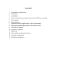
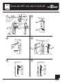
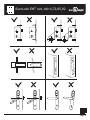
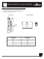
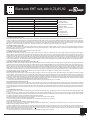
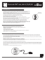
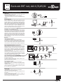
EuroLock EHT�net,�dd=0,72,85,92
User
manual
www.ironlogic.ru
CONTENT:
1. Available modifications.
2. Assembly
3. Installation
4. How to select the cylinder for Eurolock EHT net correctly
5. Introduction
6. Specification
7. Operation and programming in the office mode
8. Operation and programming in the hotel mode
9. The MODE Button
10. Firmware updates
11. Batteries
12. Connecting peripheral devices
13. Auxiliary equipment
14. Warranty obligations
EuroLock EHT�net,�dd=0,72,85,92
1. AVAILABLE MODIFICATIONS
A
B
dd
dd=0 mm
1) dd=72 mm
2) dd=85 mm
3) dd=92 mm
2. ASSEMBLY
30
-70
mm
www.ironlogic.ru
Page 2
EuroLock EHT�net,�dd=0,72,85,92
3. INSTALLATION
1
2
VERY
IMPORTANT!
Only two screws!
Not to turn off
the others!
max 30 mm
1
3
2
3
4
90°
5
6
Page 3
EuroLock EHT�net,�dd=0,72,85,92
3. МОНТАЖ
<35°
>35°
www.ironlogic.ru
Page 4
EuroLock EHT�net,�dd=0,72,85,92
4. HOW TO SELECT THE CYLINDER FOR EUROLOCK EHT NET CORRECTLY?
The cylinder or the cylinder mechanism of the lock are enclosed in a standard case, which
provides interchangeability of cylinders of different manufacturers since they are made
in accordance with a single standard. To select a cylinder of a necessary length (L) in
dependence of your leaf thickness (Т) use the table.
Leaf pattern
Cylinder pattern
T
L
Leaf thickness
T (mm)
30
40
50
60
70
Cylinder length
L (mm)
80
90
100
110
120
www.ironlogic.ru
Page 5
EuroLock EHT�net,�dd=0,72,85,92
5. INTRODUCTION
Congratulations on your purchase of access control system with easy installation, usage and programming. Eurolock EHT net is a proximity reader and controller
powered by 3 AAA 1,5V batteries. To open the lock from the outside bring the card to it, and from the inside just press the doorhandle. Eurolock EHT net is unique
since it can be installed almost in any existing door taking only 10 minutes for assembly and programming. The system provides possibility to users and administrators
to create and update a flexible room access control system within RS-485 or WiFi * network as an option, using special software, as well as autonomously without
PC usage.
There are two operation modes of Eurolock EHT net model:
In the Office mode the lock can be opened only by cards listed in the lock controller database. When special software is used, access cards will follow time and day
of the week limitations.
The Hotel mode takes into account all aspects of security and life activities in hotels / hostels / student campuses etc. It allows creation of guest cards, personnel cards
and special cards with specified access rights and protection against copying or card loss. The Hotel mode operates only within special software.
6. SPECIFICATION
Operating frequency: 125 KHz
Standard of cards/keyfobs: EM Marine, HID ProxCard II, Temic
Number of keys/cards (max): 2024 pcs.
Number of recorded events (max): 2048 pcs.
Integrated permanent memory (EEPROM)
Distance of reading: 2-4 cm
Power consumption: 30mкA (in standby mode)
Power: 1.5V X 3 pcs. of standard AAA batteries
Communication lines: Micro USB, RS485, WiFi* optional
Output reader interface: Dallas Touch Memory, Wiegand 26*
Sound/light indication: buzzer signal, 3- color LED
Setup of lock opening duration: 0 to 220 sec.
Operating temperature: -30°С +60°С (except batteries)
Case material: silumin, steel
Case colour: silver
7. OPERATION AND PROGRAMMING IN THE OFFICE MODE
Using master-card or PC, a database containing card-keys is created and recorded into the lock controller memory. The door is always closed; when a valid card is
presented, a beep sounds and a green LED is flashing; while the green LED is flashing, one can press the lock handle and open the door. The lock is automatically
locked after the handle is released or in 3 seconds. If the card has no access rights, a beep sounds and a red LED flashes. In this case the door stays closed when
the handle is turned. One can leave the room from the inside by pressing the handle.
MASTER-CARD ASSIGNMENT
Important note! This operation shall be performed BEFORE LOCKING THE DOOR!
The electronic lock is supplied with cleared memory, i.e. keys for passage are not programmed. After assembly on the door, cable and battery connection,
at least one user key shall be available besides the master-card.
To assign the master-card, the first switch-on condition shall be met (no cards in the lock memory).
Put 3 AAA batteries into the battery compartment maintaining polarity. After powering up, the lock gives short beeps and the red LED flashes for 16 seconds. This
indicates that the lock memory is empty and the lock is ready for master-card recording. While the signal is given (within 16 seconds), bring the card to the reader; as
a result, it will be recorded into the lock memory as the master-card. Termination of short signals confirms that the first master-card is recorded successfully. To add
several master-cards, bring as many cards as you want to program for this lock into close proximity with the lock one by one. When a new card is brought, the lock
gives a short beep and the green LED flashes. The exit from the master-card assignment mode is performed automatically 18 seconds after last touch. The lock notifies
you of the exit from the master-card assignment mode by a series of five short signals and the red LED flashing.
If no card was recorded as the master-card, repeat the powering procedure. The master-card recording procedure described above can be performed only when the
lock memory is absolutely empty. In the future, use the master-card (-s) created by you for programming.
Master-card
- Adds and deletes standard and blocking cards.
- Creates additional master-cards.
- Switches on/off the “ACCEPT” operation mode.
- Switches off the Blocking operation mode.
- Service lock opening.
Card hierarchy
Mastercard
Blocking
card
Standard
card
Blocking card
- Card for passage.
- Has the privilege to block (unblock) entry using standard cards.
- Turns the Free access and Blocking operating modes on and off.
Standard card is used for entry only.
PROGRAMMING WITH A MASTER CARD IN THE OFFICE MODE
In order to move on to programming the required function use short (less than 1 second) and long (hold for 6 seconds) touches with the master card. In the
,
programming mode, the lock will always reset to initial state 16 seconds after the last contact with the card reader; it will notify you with a series of five short
sound
signals and a flashing red LED.
www.ironlogic.ru
Page 6
EuroLock EHT�net,�dd=0,72,85,92
Programming using a master card
1. Adding standard cards
2. Adding blocking cards
3. Adding master cards
4. Erasing individual cards
5 Erasing all cards (lock controller memory)
6. Setting the door opening time
7. Transfer to the Blocking mode
8. Transfer to the Accept mode
9 Transfer to the Free access mode
1lM
1lM
1 s M, 1 l M
2 s M, 1 l M
3 s M, 1 l M
4sM
1lB
5sM
handle down, 1 l B
1...5 - the number of contacts
l - long contact
( hold the card for
approximately 6 seconds)
s - short contact
(hold the card for less than 1
second)
M - master card
S - standard card
B - blocking card
7 1. Adding standard cards (1 l M)
Touch the reader with the master card and hold it (long contact) At the moment of contact, the reader will give a short sound signal confirming the master card recognition, and after 6 seconds it will give a second signal indicating that the reader is now in the mode for adding standard cards. After that, remove the master card.
In order to add new cards, touch them to the reader one by one, with a less than 16 second interval between the contacts. The reader will give a short confirmation
signal at each contact with a new card. If the card is already in the memory, there will be two short signals. Exiting the mode is either automatic, 16 seconds after the
last contact, or when touched with the master card. The reader will notify you of exiting the mode with a series of 5 short signals.
7.2. Adding blocking cards (1 l M)
In the mode for adding standard cards, touch the reader with the selected card and hold for approximately 3 seconds, until a long signal sound (that is, first a short
signal will be given, and then a long signal indicating that a blocking card was added). If no more cards are added, a series of short signals indicating the exit from
the programming mode will be given.
A blocking card opens the lock when the card is removed from the reader.
7.3. Adding master cards (1 s M, 1 l M)
Briefly touch the reader with a master card (short contact). At the moment of contact, the controller will give a short signal confirming the master card recognition;
within 6 seconds, touch the reader with the master card and hold (long contact). At the moment of contact, the reader will give two short signals indicating the second
contact with the master card in the programming mode, and after 6 seconds there will be a single signal indicating that the lock has transitioned to the master card
assignment mode. After that, remove the master card. In order to add new master cards, place them to the reader one by one, with an interval between the contacts
no longer than 16 seconds. The reader will give a short confirmation signal at each contact with a new card. If the card is already entered into the memory as a master
card, no signal will be given. The exit from the master card assignment mode takes place automatically 16 seconds after the last contact. The controller will notify you
of exiting the mode with a series of 5 short signals.
7.4. Erasing standard cards using the master card (2 s M, 1 l M)
Briefly touch the reader with a master card twice (short contacts). At the moment of the first contact, the reader will give a short signal confirming the master card
recognition. At the moment of the second contact, the reader will give two short signals indicating the second touch with the master card in the programming mode;
within no more than 6 seconds place the master key to the reader and hold (long contact). At the moment of the third contact, the reader will give three short sound
signals, and after 6 seconds a single signal indicating that the reader is now in the standard card erasure mode. After that, remove the master card. In order to erase
cards, place them to the reader one by one, with an interval between the contacts no longer than 16 seconds. The reader will give a short confirmation signal at each
contact with a card being erased. If the card has not been recorded in the memory, there will be two short signals. Exiting the mode is either automatic, 16 seconds
after the last contact, or when touched with the master card. The reader will notify you of exiting the mode by a series of 5 short signals.
7.5. Erasing reader memory (3 s M, 1 l M)
Briefly touch the reader with a master card three times (short contacts). At the moment of the first contact, the reader will give a short signal confirming the master
card recognition. At the moment of the second contact, the reader will give two short signals indicating the second touch with the master card in the programming
mode. At the moment of the third contact, the reader will give three short signals indicating the third touch with the master card in the programming mode; within no
more than 6 seconds place the master key to the reader and hold (long contact). At the moment of the fourth contact, the reader will give four short signals, and after
6 seconds a series of short signals indicating that the reader memory is erased and the reader has exited from the programming mode. After that, remove the master
card. Transition to the programming mode will take place automatically after powering up.
* - At the moment when the entire base is erased using a master card, the programmed opening time is not erased.
7.6. Programming the opening time (4 s M)
Briefly bring the master card to the reader four times. At the moment of each touch, the controller will give signals confirming the master card recognition, and their
number will correspond to the number of contacts. At the moment of the fourth contact, the controller will give four signals correspondingly, and transfer to the opening
time programming mode. Within 6 seconds from the last contact, turn the interior lock handle downward for a period of time you wish to program as the opening time.
A green LED will blink at the moment when the opening time is programmed. After the handle is released, the controller will emit a signal and record the time into
memory.
7.7. The Blocking mode (1 l B)
In the Blocking mode, entry is allowed using blocking cards, and blocked for standard cards. The Blocking mode is set using a blocking card (Adding blocking cards,
see c. 6.2).
In order to transit to the blocking mode, hold the blocking card to the reader for approximately 3 seconds, until a long continuous signal sounds, which indicates
activation of the blocking mode. All standard cards are blocked in this mode. When using a standard card, the lock does not open and gives a series of short signals.
The exit from the blocking mode to the standard mode is performed as follows:
A) similarly to transition to the blocking mode using a blocking card (hold until a series of short signals)
B) brief touch with a master card (a series of short signals)
* In the event of power loss, a previously set Blocking mode is maintained even after power is restored.
7.8. The Accept mode (5 s M)
The Accept mode is used to record all the cards brought into contact.
In this mode, a card brought to the reader triggers opening the door and, simultaneously, it is recorded into the reader memory. The mode is used to recover user
database without collecting customers’ cards.
In order to activate this mode, a master card is necessary. Briefly bring the master card to the reader five times. At the moment of each touch, the reader will give
signals confirming the master card recognition, and their number will correspond to the number of contacts. At the moment of the fifth contact, the reader will give five
signals correspondingly, and another long signal confirming a transition to the Accept mode. In order to exit this mode, bring the master card to the reader; the exit
from the mode is indicated by a series of short signals.
* In the event of power loss, a previously set Accept mode is maintained even after power is restored.
www.ironlogic.ru
Page 7
EuroLock EHT�net,�dd=0,72,85,92
7 .9. The Free access mode (handle down, 1 l B)
The Free access mode switches the lock to constantly open mode. This mode allows opening doors without locks in an emergency situation, as well as for a specified
period of time (work shift, break, conference etc.).
In order to switch to the Free access mode, press the inside lock handle and hold it, bring the blocking card to the reader and hold for approximately 3 seconds until
a long continuous signal sounds, which corresponds to activation of the Free access mode. In this mode, the lock is opened by simply pressing the handle (without
a card).
The exit from the Free access mode to the standard mode is performed as follows:
A) similarly to transition to the Free access mode using a blocking card (hold until a series of short signals)
B) brief touch with a master card (a series of short signals)
* In the event of power loss, a previously set Blocking mode is maintained even after power is restored.
8. OPERATION AND PROGRAMMING IN THE HOTEL MODE
The HOTEL mode only operates when controlled by a specialized software and the RF-1996 adapter, installed on a computer. The software, in conjunction with the
RF-1996 adapter, controls the operations related to configuring and setting the locks, as well as checking out and editing guest and personnel cards, and special
purpose cards in HOTEL mode.
The principle of operation in the HOTEL mode:
1st stage, plan for locking the hotel
Using specialized software, a plan for locking the hotel is created on a computer. There we will create system users, doors, time zones etc. We can also determine
which users have access to which doors and when.
2nd stage, recording the locking plan settings into the locks.
The settings created in the hotel locking plan are to be recorded in the locks using the RF-1996 adapter. After the record entry is made, the lock will have the following
data:
- Door number
- Current time
- Time zones
- Entry rules for personnel
- Entry rules for guests
- Rules for using special purpose cards
3rd stage, issuing cards using a computer
Now that the locks are set up and have the rules for locking the hotel in the memory, we can issue the cards. Using the software and the RF-1996 adapter, the administrator can record the following data into the card’s memory on a computer.
- Date and time of card activation
- Date and time of card expiration
- Time zones for card activity
- List of doors that can be opened
A detailed set of instructions on setting/operation in the HOTEL mode and a list of specialized software compatible with locks in the HOTEL mode can be found at the
manufacturer’s website www.ironlogic.ru.
SOFTWARE
HOTEL
USB
www.ironlogic.ru
Page 8
EuroLock EHT�net,�dd=0,72,85,92
9. THE MODE BUTTON
The MODE button is located on the inside lock plate, on the battery compartment electronic circuit board. The button
is intended for setting the lock operation mode (OFFICE or HOTEL) and programming individual functions.
SWTICHING BETWEEN THE MODES (OFFICE / HOTEL ): disconnect one power supply battery from the compartment, press the MODE button and hold it, insert the power battery into the compartment and release the button.
No later than in 5 seconds, briefly press the button once: 2 signals will sound (the HOTEL mode) No later than in 5
seconds, briefly press the button once: 1 signal will sound (the OFFICE mode)
The programming mode is exited 10 seconds after the MODE button is last pressed.
MODE button
DELETING EXISTING KEYS IN THE OFFICE MODE
If one or more user keys you have access to need to be deleted, complete the following procedure:
Without turning off the power, press the MODE button and hold it; after 5 seconds a signal will sound, release the
button and place the card(s) that you want to delete to the reader.
The procedure completes 16 seconds after last card is touched or the door handle is pressed from the inside.
DELETING ALL KEYS FROM THE LOCK MEMORY (SWITCHING TO THE FACTORY SETTINGS)
In order to fully reset the settings and switch to the factory settings, complete the following procedure:
Disconnect one power supply battery from the compartment, press the MODE button and hold it, insert the power
battery into the compartment and continue to hold the button. After 5 seconds a signal will sound; continue to hold
the button; after 10 seconds a long signal will sound indicating that all settings have been reset.
Press the inside door handle to switch to the factory settings (See c. 6)
10. FIRMWARE UPDATES
Eurolock EHT Firmare can be modified using the Lock Commander software.
Firmware can be downloaded using a Micro USB connector or the RF-1996 adapter.
Depending on version and firmware, the lock can operate according to the following algorithms:
:
- Standalone mode without software
- Standalone mode with software
- As part of a RS-485 network, with software
- As part of a WiFi* network, with software
- Reader bundled with the lock control, connected to the controller using Dallas Touch Memory or Wiegand 26*
Available upgrades are on the website www.ironlogic.ru
11. BATTERIES
When using alcaline batteries with capacity over 1500 mAh, the lock will operate through no less than 20,000 openings or about 2 years in the standby mode.
The lock controls the battery discharge level and informs the user of the need to change the batteries by means of a light signal, using the following indications:
LOCK OPERATING WITH BATTERIES IN NEED OF REPLACEMENT
When a card is brought to the lock reader, the LED is not flashing, which means the batteries need to be replaced. If warnings are ignored, the batteries may discharge
fully and the lock will stop functioning.
OPENING A LOCK WITH FULLY DISCHARGED BATTERIES IN CASE OF EMERGENCY
When batteries are fully depleted, the lock remains in the Locked state in order to prevent unauthorized access. It would still be possible to exit from inside the room.
In order to access the room and replace the batteries, use one of the two following methods:
1) If a deadlock with a mechanical cylinder is installed, use the mechanical key to open the lock.
2) If your lock design prevents controlling the bolt using a mechanical cylinder or the lock does not have a mechanical cylinder, use external power supply by means of a
micro USB*. In order to do that, supply power through a micro USB connector installed on the reader, touch the assigned card, open the door and replace the batteries.
After battery replacement all user keys will still be operational, since the lock memory is energy permanent. The lock uses 3 1.5V AAA batteries. Observe polarity when
replacing the batteries.
* Micro USB cable from a mobile phone manufactured after 2010 can be used.
micro USB
USB
www.ironlogic.ru
Page 9
EuroLock EHT�net,�dd=0,72,85,92
12. CONNECTING PERIPHERAL DEVICES
MICROUSB
The micro USB connector located on the lock reader case
performs the following functions:
- lock firmware updates ( Lock Commander Software)
- external power supply in the event of lock batteries being
depleted.
micro USB
RF-1996 ADAPTER
RF-1996 adapter executes data transfer between the lock
and the computer using a contact-free method by means of
a reader antenna. It is also capable of performing firmware
updates. Antenna location is marked with a sticker label on the
bottom of the RF-1996 adapter case. In order to transfer data
to/from the lock memory, press the RF-1996 adapter antenna
to the lock reader antenna. In order to establish a sure connection, the distance between the RF-1996 adapter antenna
and lock reader antenna should not exceed 3 cm.
USB
USB
PC
lock
RF-1996 ADAPTER
EXTERNAL LOCK OPENING BUTTON
If necessary, an external lock opening button can be connected to the lock. In order to connect the button, use a 2-contact
socket located on the inner plate of the lock, on the electronic
circuit board below the battery compartment. When the external button is pressed, a beeper sounds and the green LED
flashes. While the green LED is blinking, turn the handle and
open the door before the opening time has expired (the default is 3 seconds). The door opening time is programmable
(0 to 220 seconds).
USB
LOCK OPERATION WITHIN RS-485 NETWORK
Eurolock EHT locks may be connected into a network using
RS-485 interface and operate under control from a computer.
Specialized software (see www.ironlogic.ru) allows programming the locks, controlling their operation and downloading
events. However, decisions regarding granting card/key access are made by the lock itself, regardless of whether it is
connected to a PC or not.
The locks are connected sequentially. When working in a network, in addition to power supply from 3 batteries, an external
+12V power supply should be provided in order to maintain
uninterrupted operation of the RS-485 network.
USB ConverterRS-485
DOOR SENSOR (GERKON)*
*This modification requires a change in lock firmware.
If necessary, a door opening sensor (gerkon) can be connected to the lock. In order to connect the door opening sensor,
use a 2-contact socket located on the inner plate of the lock,
on the electronic circuit board below the battery compartment.
B
A
EuroLock�EHT�net
№1
LOCK OPERATION WITHIN A WI-FI NETWORK
Electronic lock module Eurolock EHT net is ready for operation within a WiFi network.
In order to connect, Eurolock WiFi module should be purchased and lock firmware modified.
EuroLock�EHT�net
№2
EuroLock�EHT�net
№3
EuroLock EHT net
the last
WiFi
router
EuroLock�EHT�net
EuroLock�EHT�net
EuroLock�EHT�net
External DMCS controller *
*This modification requires a change in lock firmware.
Eurolock EHT net can be connected to an external DMCS
controller, such as :
EM Marin reader, HID PROX II , Temic, bundled with the lock
control, connected to an external DMCS controller using Dallas Touch Memory or Wiegand 26*.
FIRE ALARM *
*This modification requires a change in lock firmware.
A fire alarm can be connected to a lock.
When a fire alarm signal is received, the lock switches to free
entry mode.
In order to switch the lock to operating mode, bringing the
master card to the lock is sufficient.
In order to connect a fire alarm use a contact connector located on the electronic circuit plate of the lock.
Fire device
relay output
www.ironlogic.ru
Page 10
EuroLock EHT�net,�dd=0,72,85,92
13. AUXILIARY EQUIPMENT
RF1996 ADAPTER
- for setup and configuration of locks using a computer and
subsequent card programming in the OFFICE/HOTEL mode.
- for updating lock firmware.
USB
PC
RF-1996 ADAPTER
LOCK COMMANDER SOFTWARE
- for setup and configuration of locks using a computer and
subsequent card programming in the OFFICE/HOTEL mode.
- for updating lock firmware.
lock
Lock’s
der
o
C mman
RS-485
USB
USB
HOTEL Software
- for operating and configuring locks in the HOTEL mode.
- for issuing and editing guest cards, personnel cards and
special purpose cards.
- reviewing lock events
- reading events from lock memory
- monitoring personnel actions.
SOFTWARE
HOTEL
USB
CARDS/FOBS/BRACELETS
- contactless keys for the lock
14. WARRANTY OBLIGATIONS
The manufacturer provides a warranty valid for a period of 12 months from the sales date, but no longer than 18 months from the date of manufacture.
The warranty is valid if a warranty card is filled out and certified with a stamp from the retailer.
The following are grounds for release from warranty obligations:
- failure to observe these instructions.
- mechanical damage.
- evidence of effect of water and aggressive chemicals.
- evidence of unauthorized interference with the circuits.
During the warranty period, the Manufacturer shall remedy all failures arising through his fault free of charge.
All repairs are performed at the Manufacturer's workshop.
Sale date: (L.S.)
Signature: www.ironlogic.ru
Page 11
100
90
80
70
60
50
40
30
20
10
10
20
30
40
50
60
70
80
90
100
16 mm
109
TOP
145
25-40 mm
12 mm
Page 12
100
90
80
70
60
50
40
30
20
10
10
20
30
40
50
60
70
80
90
100