1
CONVERTER
Z397-GUARD
USB – 485
© RF Enabled
USER MANUAL
CONTENT
1. GENERAL...................................................................................................................................3
Special capabilities...................................................................................................................... 3
2. Connection of RS-485................................................................................................................. 4
........................................................................................................................................................ 4
3. Connection to USB......................................................................................................................5
3.1 Description.............................................................................................................................5
3.2 Driver installation.................................................................................................................. 5
3.3 Port search..............................................................................................................................6
4. Operating modes..........................................................................................................................7
4.1 Mode of standard converter - "NORMAL"........................................................................... 7
4.2. Network test mode - "TEST"................................................................................................7
Command "Info"......................................................................................................................7
Command "Time"....................................................................................................................7
Command "Scan".....................................................................................................................7
Command "Ctrl"...................................................................................................................... 8
Command "Event"...................................................................................................................8
Command "Adr"...................................................................................................................... 8
List of commands.....................................................................................................................9
4.3 Network initialization mode - "ACCEPT"............................................................................ 9
4.4 Software support mode - "ADVANCED"...........................................................................10
2
1. GENERAL
The converter Z397 Guard is designed to connect devices with RS-485 interface to
personal computer.
Main characteristics:
1) Galvanic isolation up to 1000V. Direct connection of different equipment and devices to
computer may reduce considerably their characteristics due to impulse interference produced
by the computer power supply unit. Conversely, actuating device, connected to PC, may
interfere with PC operation. In most cases the galvanic isolation solves this problem.
2) Connection and power supply by USB. USB-connection allows solve two problems. The
first problem is that many computers, especially notebooks, do not have COM-port, there is
no such problem with USB-ports. The number of USB-port may be increased easily. The
second problem is connected with a power supply source; power supply from USB-port does
not require any additional power sources. It is vital for notebooks used beyond the reach of
electric supply network.
3) Virtual COM-port. After connection of converter and installation of drivers another COMport appears in the system. It is called virtual because it cannot be operated directly via
registers. This method is usually used for programs written for DOS. Modern programs,
operating with Windows, refer to different ports using drivers. From this point of view this
port is a fully-featured device. IN other words, the program, operating under the management
of Windows, cannot distinguish virtual COM-port from real and shall transmit and receive
data in normal mode.
4) Autodetection of speed. After turning on and start converter transmits data with the same
speed as they come from computer. Thus, any additional settings of speed are not required.
5) Autodetection of transmit direction. Converter operates in a half-duplex mode and detects
automatically the transmit direction. In initial condition it waits for data both from
communication channel and computer. In case of simultaneous transmit computer has the
priority. Transition from transmit condition to acceptance condition at any speed takes less
than 5 microseconds after the transmit of the last stop-bit of the data package. The transmit
direction control by RTS will be ignored and has no effect on converter operation.
6) Connection elements. Converter has two groups of connection elements.
The first group, near USB is meant to set one of four operating modes. The
modes will described below.
The second group, near RS-485, in ON position connects loading resistor
120 Ohm to AB lines. It is required to echo cancellation, if the converter is the last in the
network. Usually all the devices, operating with RS-485, may connect this resistor.
Special capabilities
Support of network controllers Z-5R Net and Martix-II Net. In special modes this controller
allows to detect and set network addresses listed upwards the controllers using any terminal
program. Additionally you may set time of controllers and read events. Besides, this significantly
simplifies initial network initialization by means of automatic correction of conflicting network
addresses and records of unknown cards by controllers.
3
2. Connection of RS-485
RS-485 interface has been developed on the basis of RS-232 and RS-422. Though RS422 interface allows connection of several devices, actually it is designed for point-to-point
connection. RS-485 allows connecting up to 256 devices at the same line using for
communication only one twisted pair. This forces to use a half-duplex mode of communication,
i.e. to transmit information only via one devices the other devices only listen. The case when one
or more devices transmit data cannot be detected by these devices, as, for example, in case with
the interfaces CAN or Ethernet. For this reason all the communication protocols are built by the
package principle of transmit with confirmation of received information.
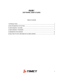
While connection of devices to the interface RS-485 take account for the following:
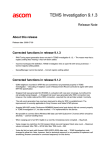
1) All the devices should be connected in linear configuration, i.e. wires should run from
one device to another in turns. Configurations in the form of a star or a tree are
inappropriate. But if it is required and the distance is not very large (up to 30 meters), you
may try, but you should remember that the interface with this configuration may not
operate.
2) Use twisted pair for connection. For example, from the 5 category cable the blue wire
connect to А, and blue and white wire — to B. If the cable is shielded, it should be
connected to G or to g.
3) To provide correct interface operation install two terminal resistors of 120 Ohm at both
ends of RS-485 lines. They are required for echo cancellation. This is vital for long ling
lines. If converter is installed at the one end, to connect resistor set the connection
element No2 in position ON.
4) To connect many devices (бmore than 20), it is recommended to place them with the
same distance from each other. You should remember that the length of the line should
not exceed 1200 meters.
5) Though the interface may physically and programmatically serve up to 255 devices, it is
not recommended to use it at the limit. Thus, if you need long communication line, try to
minimize the number of devices or at least place them at the same distance to each other.
If there are many devices, try to reduce the total line length.
C
O
N
V
E
R
T
E
R
G
A
B
g
Device 1
Device 2
A
B
A
B
120 Ohm
Connection diagram for devices with RS-485 interface.
4
3. Connection to USB
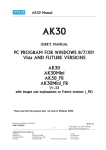
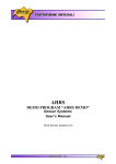
3.1 Description
This converter is connected to computer via free USB-port by the supplied cable of
"AB". Main advantages of this solution:
1) Today almost all computers are equipped with USB-ports. Notebooks often do not
have СОМ-port, but it is difficult to imagine modern computer without USB.
2) USB-ports support hot plugging, i.e. you may turn on and off such devices without
switching off the computer.
3) USB-port supply with power the connected device (up to 500 mA). Thus, the power
supply unit is not required with the problem of search of free socket.
4) All USB devices support standard Plug-&-Play. Due to this the required drivers will
be installed automatically. You only need to insert the disk and follow the
instruction of operating system.
Slot
for для
Разъём
connection
of
подключения
RS-485
RS-485
USB
Зелёный
Green
diode
светодиод
Data to
"Данные в
computer
компьютер"
Connection
Перемычкаelement
№2
No2включения
for load starting
120
Ohm 120 Ом
нагрузки
RedКрасный
diode
светодиод
Data from
"Данные из
computer
компьютера"
Connection №1
Перемычка
element
No1 for
выбора
operating
mode
режима
selection
работы
3.2 Driver installation
After the first connection of converter to computer, Windows operating system will
detect a new device. It takes about 30 сseconds. If within one minute the message about the
detection of new devices did not appear, Windows is already familiar with the device and the
required drivers have been already installed.
Thus, Windows gave the message about new device. To install drivers insert the
supplied disk in CD-drive. Set the mode of driver selection manually and indicate CD-disk
where drivers will be installed. After detection of drivers Windows will offer to install them.
You should submit. While drivers installation Windows XP will give message on the absence of
Microsoft certificate of tested compatibility. In this case continue installation. There will be two
such messages because first the driver is installed specially for USB-device and then for virtual
COM-port.
5
3.3 Port search
One of intellectual steps in driver installation is determination of a virtual COM-port
number. The logic of distribution of such numbers in Windows was not described anywhere, that
is why all the following information is the result of practical experience. Thus, Windows
reserves numbers for each new virtual СОМ-port from COM3 to COM127 and as a limit COM0.
The assigned number will be attached to the USB device and will not be assigned to any other
devices. Thus, if the computer was connected with devices generating virtual ports, at the
moment there are only two standard COM-ports – COM1 and COM2, the new port will not
necessarily be COM3.
For precise determination of number when the converter is connected proceed as
follows:
1. Right click the icon “My computer”, select the lowest point “Properties” from the
menu.
2. In the window select the bookmark
2.1. for Windows 98/Me – “Devices”
2.2. for Windows XP/2000 – «Equipment” and additionally press the button “Device
manager”
3. Left click the plus opposite the group “Ports (COM and LPT)”
4. In the opened group find the number of the device port.
Attention! Some programs cannot open ports with numbers more than 8. In this case right click to call for
contextual menu for this device and select the point "Properties". In the widow come to the bookmark
"Port Setting", press the button "Advanced" and set required port number.
This number should be indicated in the communication programs operating with the
devices. Speed settings are not required. The converter will operated at the speed set by the
communication program for the port.
6
4. Operating modes
The required operating mode shall be selected by replacement of the connection element No1 in
one of four positions. Compatibility of position and mode shall be specified at the converter
plate.
4.1 Mode of standard converter - "NORMAL"
The mode of standard converter is RS-485. Autodetection of speed and transmit direction.
Indication of transmit direction.
4.2. Network test mode - "TEST"
Controller network test mode. This mode of converter allows testing and setting of network on
the base of network controllers Z5R-Net and Matrix-II Net.
To operate in this mode open the converter port using any terminal program, for example,
HyperTerminal, and set the following communication parameters:
- Speed — 230400;
- Data bit — 8;
- Parity — no;
- Stop bits — 1;
- Flow control — no.
After input of any command press button “Enter”.
Command "Info"
After connection to computer to test the communication give the identification command "I". In
case of correct connection the window of the terminal program will display the following
information:
Z397-Guard converter S/N:00037
Pulsar Ltd. +7(812)703-77-65, +7(495)787-70-66
Copyright 2008 RF Enabled
http://www.ironlogic.ru
build Jan 14 2009 15:55:34
---------------------------------Current mode - Test
Converter will give reply to this command in any mode.
Command "Time"
Allows setting time in controllers.
Examples of commands:
T – request of time
T 12:30:00 - time setting only
T 21-01-09 – date setting only
T 12:30:00 21-01-09 – time and date setting
Time is 0:00:00 0-00-00 Time and Date not setup - time and date were not set
Time is 12:30:00 21-01-09 – date and time
After any command, if and date are set, the timers of all the detected controllers выполняется
(see command "Scan") will be synchronized with timers of converters.
Command "Scan"
Allows detection of connected controllers.
Examples of commands:
7
S – scan the line RS-485
While scanning controller detects controllers, if their network addresses are already known or if
they are out of the range 2 - 33, they are reassigned to the first free network address.
Result of the command operation
Scan start
Net addr = 4, Serial number = 139, type - Z5R-Net
Net addr = 6, Serial number = 151, type - Z5R-Net - NEW
Net addr = 7, Serial number = 132, type - Matrix-II-Net - REMOVED
The additional message "NEW" – indicates that the controller was detected for the first time, and
the message "REMOVED" – indicates that the controller has not been detected and will be
removed from the list.
Command "Ctrl"
Outputs additional information on detected controllers.
Example of command:
С – output all the detected controllers
С 4 – output information on controller with network address 4
Result of the command
Net addr = 4, Serial number = 139, type - Z5R-Net
Door times (*0.1s): open lock 30, wait open 0, wait close 0
Timezone1 from 00:00 to 23:59 days-7F
Timezone2 from 00:00 to 23:59 days-7F
Timezone3 not active
Timezone4 not active
Timezone5 not active
Timezone6 not active
Timezone7 not active
Cards use 11 from 2024
Command "Event"
Outputs the list of new events for one or all controllers.
Example of command:
E – output all new events for all detected controllers
E 4 – output all new events for controller with network address 4
Result of the command
Ctrl
Ctrl
Ctrl
Ctrl
Ctrl
4
6
6
6
7
SN(139) Pnt[2480:2480] 0 events.
SN(151) Pnt[17A8:17B8] 2 events.
EVENT[17A8] 23/02 19:28:51 {00} Door 0. Open by button
EVENT[17B0] 23/02 19:28:51 {10} Door 0. Passage was
SN(132) Pnt[00D8:00D8] 0 events.
Command "Adr"
Enable the change of the controller network address.
As the first parameter indicate a serial number of controller, as the second parameter – the
network address. The new address should be within the range of 2-33 and free.
Example of the command
A 139 33 – set the controller S/N 139 network address 33.
8
Result of the command
Controller 139 change net address from 4 to 33.
After the command "Scan"
Net addr = 6, Serial number = 151, type - Z5R-Net
Net addr = 7, Serial number = 132, type - Matrix-II-Net
Net addr = 33, Serial number = 139, type - Z5R-Net
List of commands.
No
Command
Description
1
I(Info)
Request for information on converter
2
T(Time)
3
S(Scan)
4
C(Ctrl)
5
E(Event)
A(Adr)
6
A SN N
SN – serial number
N – new network address
Request/setting of date and time
Allows setting of time and date by
different commands
Scanning RS-485
all addresses beyond the range 2..33
will be reassigned automatically
Receipt of information for the specified
controller or for all controllers
Request of information on new events
for the specified controller or all
controllers
Set network address
(N = 2..33)
new address should be free
Result
Information on converter and
established licenses
Current date and time will be
recorded into controllers while the
following events scanning
Information on detected controllers
Additional information on controller
Issue of messages on events
Message on successful setting or on
failure causes
4.3 Network initialization mode - "ACCEPT"
This mode is meant for quick start of the set network without the software installation at the
computer.
In this mode converter regularly scans the network to detect the controllers. It sets network
addresses for the detected controllers. Then events are read. After detection in events the attempt
of access by unknown card, it records the number of the card into the controller, and after that
gives a remote command for a door release. Operation in this mode may be controlled using the
terminal program. The connection parameters — analogous to the Test mode:
- Speed — 230400;
- Data bits — 8;
- Parity — no;
- Stop bits — 1;
- Flow control — no.
In this mode all events occurring in controllers will be displayed automatically. You may also set
time using the command "Time" (see mode TEST).
Scan
Scan
Scan
Ctrl
Ctrl
Scan
Scan
Ctrl
Card
Ctrl
Ctrl
Scan
result {}
result {}
result {2,6,7}
2 EVENT[2488]
2 EVENT[2490]
result {2,6,7}
result {2,6,7}
6 EVENT[1548]
success added.
6 EVENT[1550]
6 EVENT[1558]
result {2,6,7}
23/02 19:28:51 {05} Door 1. Open by key num [1]
23/02 19:28:51 {11} Door 1. Passage was
23/02 19:28:55 {02} Door 0. Unknown key [1901] 162,32936
23/02 19:28:55 {08} Door 0. Open by network
23/02 19:28:55 {10} Door 0. Passage was
9
4.4 Software support mode - "ADVANCED"
This mode is meant for converter operation under the management of special software. In this
mode converter performs some functions improving software reliability and providing license
protection.
10