1
DUAL SWING GATE OPENER
OWNER’S MANUAL
DUAL SWING GATE OPENER
OWNER’S MANUAL
Thank you very much for choosing an Ironton™ product. For future reference, please complete
the owner’s record below:
Serial Number/Lot Date Code: _______________ Purchase Date: _______________
Save the receipt, warranty and these instructions. It is important that you read the entire manual
to become familiar with this product before you begin using it.
This Swing Gate Opener is designed for certain applications only. The distributor cannot be
responsible for issues arising from modification or use of this product in an application for
which it was not designed. We strongly recommend that this product not be modified and/or
used for any application other than that for which it was designed. If you have questions about
a particular modification or application, DO NOT use the product until you have first contacted
the distributor to determine if the product can or should be modified or used in such an
application.
For technical questions please call 1-800-222-5381.
Table of Contents
Table of Contents...............................................................................................................................1
Intended Use.......................................................................................................................................1
Entrapment Protection.......................................................................................................................2
Technical Specification......................................................................................................................2
General Safety Rules..........................................................................................................................2
Important Safety Considerations.......................................................................................................3
Safety Labels......................................................................................................................................4
Important Installation Safety Instructions.........................................................................................4
Gate Opener and Mounting Hardware...............................................................................................6
Step 1 — Prepare for Installation........................................................................................................8
Step 2 — Install the Gate Opener on the Gate....................................................................................9
Step 3 — Prepare the AC Power Supply.........................................................................................14
Step 4 — Mount the Control Box.....................................................................................................15
Step 5 — Connect the Power Cables..............................................................................................15
Step 6 — Program the Remote Control................................................................................. ........18
Step 7 — Set Operating Controls....................................................................................................18
Step 8 — Set the Gate Closed/Open Position................................................................................21
Operation..........................................................................................................................................21
Emergency Release..........................................................................................................................21
Troubleshooting................................................................................................................................22
Maintenance.....................................................................................................................................23
Replacement Parts...........................................................................................................................23
Wiring Optional Accessories............................................................................................................24
Limited Warranty..............................................................................................................................26
Intended Use
WARNING:
Read carefully and understand all ASSEMBLY AND OPERATION
INSTRUCTIONS before operating. Failure to follow the safety rules and
other basic safety precautions may result in serious personal injury.
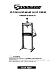
Item #47825
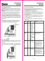
This Automatic Swing Gate Opener is intended for use with vehicular swing gates. It is designed
for swing gates weighing up to 650 lbs. or up to 12ft. long. This is an ideal gate opener for
wood, chain link, tubular metal, vinyl, aluminous, and tube gates in light wind environments.
The gate opener can be used in Class I and Class II applications.
• Residential Vehicular Gate Opener – Class I – A vehicular gate opener (or system) intended
for use in a home of one- to four single family dwelling, or a garage or parking area associated
there with.
• Commercial/General Access Vehicular Gate Opener – Class II – A vehicular gate opener (or
system) intended for use in a commercial location or building such as a multifamily housing
unit (five or more single family units), hotel, garages, retail store, or other building servicing the
general public.
1 of 26
DUAL SWING GATE OPENER
OWNER’S MANUAL
• Industrial/Limited Access Vehicular Gate Opener – Class III – A vehicular gate opener (or
system) intended for use in an industrial location or building such as a factory or loading dock
area or other locations not intended to service the general public.
• Restricted Access Vehicular Gate Opener – Class IV – A vehicular gate opener (or system)
intended for use in a guarded industrial location or building such as an airport security area or
other restricted access locations not servicing the general public, in which unauthorized
access is prevented via supervision by security personnel.
DUAL SWING GATE OPENER
OWNER’S MANUAL
General Safety Rules
WARNING:
Entrapment Protection
• Read and understand all instructions. Failure to follow all instructions may result in
serious injury
• The warnings, cautions, and instructions discussed in this manual cannot cover all possible
conditions or situations that could occur. The operator must use common sense and caution
when using this product.
• DO NOT allow persons to operate or assemble this product until they have read this manual and
have developed a thorough understanding of how the product works.
Technical Specification
• Never let children operate or play with gate controls. Keep the remote control away from children.
• Always keep people and objects away from the gate. No person should cross the path of the
moving gate. Do not allow children to play around the gate.
• Test the gate opener monthly. The gate MUST reverse on contact with a rigid object or stop when
an object activates the non-contact sensors. After adjusting the force or the limit of travel, retest
the gate opener. Failure to adjust and retest the gate opener properly can increase the risk of
injury or death.
• Use the emergency release only when the gate is not moving.
• Keep gates properly maintained. Read the owner’s manual. Only a qualified service person
should make repairs to the gate hardware.
• The entrance is for vehicles only. Pedestrians must use separate entrance.
• To AVOID damaging gas, power, or other underground utility lines, contact underground utility
locating companies BEFORE digging.
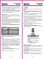
This gate opener complies with Gate Operator Safety Standard, UL 325. It uses a built-in
entrapment sensing system as the primary type of entrapment protection and has provisions for
connecting secondary entrapment devices.
Built-In Entrapment Protection
The gate opener will stop and reverse direction if it comes into contact with an obstruction
while the gate is opening or closing. If the gate opener obstructs twice while opening or closing,
an alarm will sound. The alarm will continue to sound until the power is turned off or until the
gate opener receives an intended signal from a hard wired control (e.g., push button or wired
keypad; neither is included with the gate opener). Wireless controls will not turn off the alarm.
Secondary Entrapment Protection Provisions
The gate opener has provisions for connecting third party contact and non-contact secondary
entrapment protection devices such as safety edge sensors and photoelectric sensors.
Property
Input
Capacity
Max. actuator travel
Dimensions
Ambient Temperature
Specification
120V~ 60Hz
Gates weighing up to 650 lbs. or up to 12ft. long
15-1/4''
31-1/2'' × 4'' × 3-1/4''
-20°C~ +50°C (-4°F to 122°F)
CAUTION: Changes or modifications not expressly approved by the distributor could
void the user's authority to operate the equipment.
NOTICE
This equipment has been tested and found to comply with the limits for a Class B digital device,
pursuant to part 15 of the FCC Rules. These limits are designed to provide reasonable
protection against harmful interference in a residential installation. This equipment generates,
uses, and can radiate radio frequency energy and, if not installed and used in accordance with
the instructions, may cause harmful interference to radio communications. However, there is no
guarantee that interference will not occur in a particular installation. If this equipment does
cause harmful interference to radio or television reception, which can be determined by turning
the equipment off and on, the user is encouraged to try to correct the interference by one or
more of the following measures:
• Reorient or relocate the receiving antenna.
• Increase the separation between the equipment and receiver.
• Connect the equipment into an outlet on a circuit different from that to which the receiver is
connected.
• Consult the dealer or an experienced radio/TV technician for help.
2 of 26
SAVE THESE INSTRUCTIONS
Important Safety Considerations
• DO NOT modify the product in any way. Unauthorized modification may impair the function
and/or safety and could affect the life of the product. There are specific applications for which
the product was designed.
• Inspect the work area before each use. Keep the work area clean and dry. Damp or wet work
areas can result in injury.
• Keep children away from work area. DO NOT allow children to handle this product.
• Dress properly. DO NOT wear loose clothing or jewelry, which can get caught in moving
parts. Contain long hair.
• Store idle equipment. Store the product when not in use. Store it in a secure place out of the
reach of children. Inspect it for good working condition prior to storage and before re-use.
3 of 26
DUAL SWING GATE OPENER
OWNER’S MANUAL
• Use the right tool for the job. DO NOT attempt to force a small equipment to do the work of
larger industrial equipment. There are certain applications for which this equipment was
designed. It will do the job better and more safely at the capacity for which it was intended.
DO NOT use this equipment for a purpose for which it was not intended.
• Check for damaged parts. Before using this product, carefully check that it will operate
properly and perform its intended function. Check for damaged parts and any other
conditions that may affect the operation of this product. Replace damaged or worn parts
immediately. Never operate this product with a damaged part.
• DO NOT overreach. Keep proper footing and balance at all times to prevent tripping, falling,
back injury, etc.
• DO NOT use the equipment when tired or under the influence of drugs, alcohol, or
medication. A moment of inattention while operating this equipment may result in serious
personal injury.
• Industrial or commercial applications must follow OSHA requirements.
• The warnings and instructions in this manual do not cover all possible conditions or
situations that may occur. The user must always be aware of their environment and ensure
that they use the product in a safe and responsible manner.
Safety Labels
DUAL SWING GATE OPENER
OWNER’S MANUAL
• The gate must be installed in a location so that enough clearance is supplied between the
gate and adjacent structures when opening and closing to reduce the risk of entrapment.
• The gate must be properly installed and work freely in both directions prior to the installation
of the gate opener. Do not over-tighten the gate opener clutch or pressure relief valve to
compensate for a damaged gate.
• Controls intended for user activation must be located at least ten feet (10’) away from any
moving part of the gate and where the user is prevented from reaching over, under, around or
through the gate to operate the controls. Outdoor or easily accessible controls shall have a
security feature to prevent unauthorized use.
• The Stop and/or Reset button must be located in the line-of-sight of the gate. Activation of the
reset control shall not cause the gate opener to start.
• A minimum of two (2) WARNING SIGNS (included) shall be installed, one on each side of the
gate where easily visible.
Important Installation Safety Instructions
• Install the gate opener only when:
- The gate opener is appropriate for the construction of the gate and the usage Class of the gate.
- All exposed pinch points are eliminated or guarded.
• The gate opener is intended for installation only on gates used for vehicles. Pedestrians must
be supplied with a separate access opening. The pedestrian access opening shall be
designed to promote pedestrian usage. Locate the gate such that persons will not come in
contact with the vehicular gate during the entire path of travel of the vehicular gate.
4 of 26
5 of 26
DUAL SWING GATE OPENER
OWNER’S MANUAL
DUAL SWING GATE OPENER
OWNER’S MANUAL
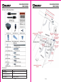
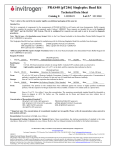
Gate Opener and Mounting Hardware
Tools Needed
• Power Drill
• Tape Measure
• Open End Wrenches — 14# &
17# or Adjustable Wrenches
• Wire Strippers
• C-Clamps — small, medium, and large
• Level
• Hacksaw or Heavy Duty Bolt Cutters
• Phillips Screwdriver
6 of 26
7 of 26
DUAL SWING GATE OPENER
OWNER’S MANUAL
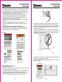
Step 1 — Prepare for Installation
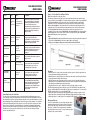
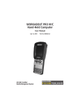
• The gate opener includes two Post Pivot Brackets. The small bracket is for a Pull-to-Open
installation and the large bracket is for a Push-to-Open installation. Make sure that you use
the appropriate bracket.
• In some cases, the installation instructions for a Pull-to-Open installation and a Push-to-Open
installation are different. Make sure that you are following the appropriate instructions.
• One gate is the Primary gate and the other gate is the Secondary gate. The primary gate
opens first and closes last. It is recommended that the Control Box be mounted on the side of
the Primary gate so as to ensure proper installation and operation of an optional electric lock.
• The gate opener is mounted to the gate and to the gate post. Both round and square posts
can be used because the Post Brackets are curved. When mounting the Post Brackets, use
bolts long enough to pass through the entire post. Four M10 x 200 bolts are included. If these
are not long enough, you will need to purchase new bolts. Concrete anchors are not provided.
When mounting the Post Brackets to wooden posts, a larger-size washer or metal plate
should be used between the bolts and the wooden post to ensure the stability of the fastening
hardware. If the post is smaller than 6" diameter or square, it should be made of metal and set
in cement to ensure its stability. The following illustration shows several options for mounting
the Post Bracket.
DUAL SWING GATE OPENER
OWNER’S MANUAL
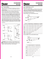
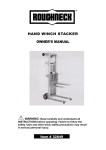
Step 2 — Install the Gate Opener on the Gate
Note: Perform Step 2 for each gate opener.
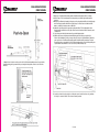
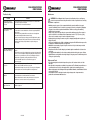
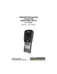
The position of the Post Bracket is important because it determines the efficiency and leverage
of the gate opener. The following illustrations and tables are required to determine the proper
mounting position for the Post Bracket. The tables show the maximum opening angle of the
gate for a given A and B. For example, if A is 6" and B is 8", the maximum opening angle of the
gate is 110°. Note: Distance A must be at least 3-1/8".
Pull-to-Open Installation — Gate is Closed (Push-Pull-Rod is extended)
Push-to-Open Installation — Gate is Closed (Push-Pull-Rod is retracted)
CAUTION: Ensure the post or wall the gate opener bracket will attach to is large
enough to handle the load of the gate. This post will be under constant stress when
opening and closing. Do not attach the bracket to a weak or unsteady post.
8 of 26
9 of 26
DUAL SWING GATE OPENER
OWNER’S MANUAL
1. Place the Post Pivot Bracket between the two Post Brackets. Insert the M10 x 30 bolt
through the center hole of the Post Bracket and Post Pivot Bracket as shown. Place an M10
washer, M10 lock washer and M10 nut on the bottom of the bolt and hand tighten.
2. Attach the Post Bracket Assembly and the Gate Bracket to the gate opener with the clevis
pins. Secure the clevis pins with the hairpin clips
DUAL SWING GATE OPENER
OWNER’S MANUAL
4. With the gate opener fully retracted and with the gate in the fully open position (for
Pull-to-Open installation) or fully closed position (for Push-to-Open installation), place the
gate opener with the Post Bracket Assembly and Gate Bracket on the gate post and the gate.
Position the Post Bracket Assembly and Gate Bracket so that the gate opener is level. While
holding the gate opener in the level position, temporarily secure it with two C-clamps.
5. Make sure that there is a minimum clearance of 1" between the gate and the gate opener and
that the gate opener and the Post Pivot Bracket are not binding. If there is not at least 1"of
clearance or if the gate opener and the Post Pivot Bracket are binding, rotate the Post Pivot
Bracket and/or move the Post Bracket Assembly to obtain the minimum clearance and
eliminate the binding. When the minimum clearance has been obtained and any binding has
been eliminated, place the M8 x 30 bolt through the aligned holes in the Post Bracket and the
Post Pivot Bracket.
Remove the clevis pin from the Gate Bracket and move the gate to the gate closed position
(for Pull-to-Open installation) or gate open position (for Push-to-Open installation), fully
extend the gate opener, and reattach the gate opener to the Gate Bracket with the clevis pin.
Repeat the above step to ensure the minimum 1" clearance and that the gate opener and
Post Pivot Bracket are not binding.
When the best position for the Post Pivot Bracket has been obtained, secure it in place with
an M8 washer and M8 nut.
3. Open the release hole plug on the top of the gate opener, insert the release key, and turn the
key 90° clockwise. This releases the motor and allows the push-pull rod to be manually
extended and retracted. To restore normal operation, turn the key 90° counterclockwise.
10 of 26
11 of 26
DUAL SWING GATE OPENER
OWNER’S MANUAL
DUAL SWING GATE OPENER
OWNER’S MANUAL
7. Remove the Post Bracket Assembly and the Gate Bracket by taking off the C-clamps.
8. Drill 10.5 mm or 7/16 inch diameter holes through the post and the gate at the marked
locations.
9. Attach the Post Bracket Assembly to the gate post by inserting four M10 x 200 bolts through
each Post Bracket and the drilled holes in the gate post. Fasten each bolt with one M10
washer, one M10 lock washer, and one M10 nut.
10. Attach the Gate Bracket to the gate by inserting two M10 x 75 bolts through the Gate
Bracket and the drilled holes in the gate. Fasten each bolt with one M10 lock washer, and
one M10 nut.
11. Cut off any part of the bolts that extend beyond the tightened nuts.
12. With the gate opener fully retracted and with the gate in the fully open position (for
Pull-to-Open installation) or fully closed position (for Push-to-Open installation), attach the
gate opener to the Post Bracket Assembly and the Gate Bracket by inserting a clevis pin
through the gate opener and the Post Pivot Bracket and another clevis pin through the gate
opener and the Gate Bracket. Secure each clevis pin with a hairpin clip.
6. Mark bolt hole locations on the post for the Post Bracket Assembly and on the gate for the
Gate Bracket by placing a mark on the post and gate through the center of each slot in the
brackets.
13. Open the release hole plug on the top of the gate opener, insert the release key, and turn
the key 90° counterclockwise. This restores normal operation.
12 of 26
13 of 26
DUAL SWING GATE OPENER
OWNER’S MANUAL
Step 3 — Prepare the AC Power Supply
WARNING: Never connect the gate opener to the power supply before all the
hardware installations have been completed.
DUAL SWING GATE OPENER
OWNER’S MANUAL
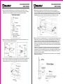
Step 4 — Mount the Control Box
Use deck screws (not provided) to mount the control box to a secure surface. Make sure that
the control box is at least 40" above the ground to protect it from rain, snow, etc.
CAUTION: This gate opener will be permanently connected to your electrical system.
Only a licensed electrician should make this connection. This gate opener must be
attached to a 10A circuit breaker with GFCI protection. Ensure all connections meet local
electrical codes and ordinances.
Below are the minimum power supply requirements. Ensure all wiring meets your local
electric code requirements.
• The gate opener control box must be hardwired to a 120V, 60 Hz power supply.
• The control box must be protected by a 10A GFCI breaker.
• Use copper wire of at least 14AWG.
• Run the wires in conduit to the control box to prevent damage to the wires from lawn
mowers, string trimmers, and grazing animals.
• The control board uses a 10A, 250V AC, Φ5*20mm fuse.
Step 5 — Connect the Power Cables
WARNING: Shock Hazard. Before connecting the AC power cable to the control box,
ensure that the AC power to the cable is turned off
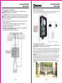
Note: Two 1.5m motor power cables are supplied with the gate opener. The motor power cable
that is connected to the opener that is mounted on the gate opposite (furthest) from the control
box (B in the illustration below) must be lengthened by splicing it to a suitable length of 5-core
cable (2×16AWG+3×24AWG). Use the appropriate size wire nuts to splice each of the 5 color
coded wires.
Important: The red and black wires in the motor power cable are 16AWG and must be spliced
to the 16AWG wires in the 5-core cable. Make sure to note which color wires are being spliced
together. When running the motor power cable between the gate opener and the control box,
make sure that the cable and splice are protected from animals, machinery, and the
environment (e.g., place the splice in an appropriate electrical box and run the cable through
PVC conduit).
14 of 26
15 of 26
DUAL SWING GATE OPENER
OWNER’S MANUAL
1. Insert the AC power supply cable (not supplied) and one of the motor power cables (supplied)
through the left strain relief and into the control box by loosening the strain relief screw
located on the bottom of the control box and feeding the cables into the control box. Make
sure that the cables reach the proper terminals in the control box. Tighten the sealing nut so
that the cables are well secured.
Insert the other motor power cable (supplied) through the right strain relief and into the
control box by loosening the strain relief screw located on the bottom of the control box and
feeding the cable into the control box. Make sure that the cable reaches the proper terminals
in the control box. Tighten the sealing nut so that the cables are well secured.
2. Connect the AC power supply cable to the control box as shown in the following illustration:
16 of 26
DUAL SWING GATE OPENER
OWNER’S MANUAL
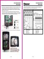
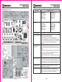
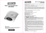
3. Connect the motor power cables to the control box as shown in the following illustration.
Note: Pull-to-Open and Push-to-Open use different wiring schemes.
Pull-to-Open
Push-to-Open
RED to MOTOR1+
BLACK to MOTOR1–
BLUE to ULT1
GREEN to COM
YELLOW to DLT1
BLACK to MOTOR1+
RED to MOTOR1–
YELLOW to ULT1
GREEN to COM
BLUE to DLT1
17 of 26
DUAL SWING GATE OPENER
OWNER’S MANUAL
Step 6 — Program the Remote Control
WARNING: Activate the gate opener only when gate is in full view, free of obstruc-
tion, and properly adjusted. No one should enter or leave the gate area while the gate
is in motion. Do not allow children to operate the remote control. Do not allow children to
play near the gate.
The gate opener receiver and remote control transmitter are set to a matching code. If you
purchase additional remote controls, the gate opener must be programmed to learn the new
remote code. The gate opener can learn the commands of up to six remote controls.
To learn remote control commands: Press and release the Learn button. The LED will display
Ln. Press the remote control button twice within 2 seconds. The LED will flash Ln for 4 seconds,
and will then display Standby (– –), indicating that the remote control command has been learned.
To erase all remote control commands: Press and hold the Learn button until the LED displays
the standby symbol (– –).
Notes
• The maximum distance from which the remote control can operate the gate opener is 60 ft.
• The control box must be located so that transmission of signals are not obstructed or
impeded by building structures, natural landscaping, or similar obstruction.
DUAL SWING GATE OPENER
OWNER’S MANUAL
To set a value for a control, follow these steps:
1. Apply power to the control board. The LED display will flash the standby symbol (– –).
2. Press and hold the FUNC button until the display shows P1. Each time you press the FUNC
button, the display will show the next code (e.g., P1, P2, P3, etc.).
3. Press the FUNC button until the code you want is displayed.
4. Press the INC or DEC button once. The display will show the current value of the control.
5. Press the INC or DEC button to set the desired value for the control. Each time you press the
INC button the numerical value increases by 1. Each time you press the DEC button, the
numerical value decreases by 1.
6. Press the FUNC button to save the value. The display will show the code for the next control.
7. If you want to set another control, press the FUNC button until the display shows the code
for the control that you want to set.
8. When you are finished setting controls, press the FUNC button until the display shows the
standby symbol (– –).
Code
Value
Single/Dual
P1
01 = single gate
(opener is connected
to MOTOR 1 on
Control Board)
10 = single gate
(opener is connected
to MOTOR 2 on
Control Board)
11 = dual gate
Default = 11
Primary/
Secondary
P2
01 = opener
connected to MOTOR
1 on Control Board is
Primary
10 = opener
connected to MOTOR
2 on Control Board is
Primary
Default = 01
Open Interval
P3
0 to 9 seconds
Default = 3 seconds
Close Interval
P4
0 to 9 seconds
Default = 3 seconds
Step 7 — Set Operating Controls
There are several controls that determine how the gate operates. Each control has a factory set
default, but it is recommended that each control be examined to ensure that it is set correctly
for the installation.
Each control has a code and range of numerical values (e.g., 1-9). The table below describes
the controls. You set the value of a control using the LED display and the FUNC, INC, and DEC
buttons.
18 of 26
Description
Control
19 of 26
(Dual gate only.) The Primary gate
opens first and closes last.
(Dual gate only.) Open Interval is the
amount of time that lapses from when
the Primary gate begins to open and
the Secondary gate begins to open. For
example, if the value is 3 seconds, the
Primary gate will begin to open 3
seconds before the Secondary gate
begins to open.
(Dual gate only.) Close Interval is the
amount of time that lapses from when
the Secondary gate begins to close and
the Primary gate begins to close. For
example, if the value is 3 seconds, the
Secondary gate will begin to close 3
seconds before the Primary gate begins
to close.
DUAL SWING GATE OPENER
OWNER’S MANUAL
Control
Code
Value
Description
Stall Force
P5
(Opener 1)
P6
(Opener 2)
1 to 9
1 = minimal force
9 = maximum force
Default = 3
Stall Force is the amount of force that the
gate opener will apply to an object that is
obstructing the gate. When the specified
force is reached, the gate opener
automatically stops and reverses direction.
The gate opener’s opening/closing force is
adjusted automatically according to the
stall force setting.
Maximum Motor P7
Running Time
(Opener 1)
(MRT)
P8
(Opener 2)
1 to 50 seconds
Default = 40
seconds
MRT is the maximum length of time that
the gate opener will run. When the
specified MRT is reached, the gate opener
will stop running, even if the limit switch is
invalid or the clutch is detached.
Safety Photocell P9
Beam System
00 = OFF
11 = ON
Default = 00
A Safety Photocell Beam System is an
optional accessory. It is either turned ON or
turned OFF. If turned ON, the gate opener
will not work until the PBS system is
equipped.
Automatic
Closing Time
1 to 99 seconds
Default = 60
seconds
Automatic Closing Time is the number of
seconds that the gate remains open before
it begins to close.
0 to 9 seconds
Default = 3 seconds
STP is the amount of time that the gate
opener operates at the slow speed when
the gate begins to open or close. See
Controlling the Speed of the Gate.
1 to 28 seconds
Default = 15
seconds
FRP is the amount of time that the gate
opener operates at the fast speed when
the gate is opening or closing. See
Controlling the Speed of the Gate.
P10
Soft Start Period Pb
(STP)
Fast Running
Period (FRP)
Pc
To return all settings to their factory default,
press the FUNC button until the Digital
Display shows Pd, and then press the INC
button or the DEC button. The Digital
Display will now show dF, which indicates
that all settings were returned to their
factory default.
Pd
Return to
Factory Settings
Controlling the Speed of the Gate
The gate opener operates at two factory set speeds: fast and slow. When the gate opens or
closes, the gate opener first operates at the slow speed for a user-specified number of seconds
(the Soft Start Period), then it operates at the fast speed for a user-specified number of seconds
(the Fast Running Period), and finally it operates at the slow speed for a number of seconds (the
Soft Stop Period) until the gate is fully opened or closed. The Soft Stop Period is not an option
that you can specify directly, it is determined by the Soft Start Period and the Fast Running
Period. To increase the Soft Stop Period, decrease either (or both) the Soft Start Period or the
Fast Run Period. To decrease the Soft Stop Period, increase either (or both) the Soft Start
Period or the Fast Run Period.
20 of 26
DUAL SWING GATE OPENER
OWNER’S MANUAL
Step 8 — Set the Gate Closed/Open Position
Note: Perform Step 8 for each gate opener.
The amount of extension of the gate opener's push-pull rod determines how much the gate
closes in a Pull-to-Open installation or how much the gate opens in a Push-to-Open installation.
Pull-to-Open Installation — If the push-pull rod is not extended enough, the gate will not
completely close. If it is extended too much, the gate may reverse and open after closing.
Push-to-Open Installation — If the push-pull rod is not extended enough, the gate will not
completely open. If it is extended too much, the gate may reverse and close after opening.
To set the push-pull-rod extension, attach the power cable to the gate opener. Use a
screwdriver to loosen the screw of Limit Switch B, slide Limit Switch B to the desired position,
and then tighten the screw. Use the remote control to open and close the gate. Adjust Limit
Switch B until the gate closes/opens properly.
Notes
• Sliding Limit Switch B toward the Gate Bracket increases the amount of push-pull rod extension.
• The position of Limit Switch A is factory set and should not be changed.
• Always place the Magnetic Ring between Limit Switch A and Limit Switch B.
Operation
• With the gate in its closed position, press and release the remote control, the gate will move
to the programmed opening position and stop.
• With the gate in its opened position, press and release the remote control, the gate will move
to the programmed closing position and stop.
• While the gate is moving, press and release the remote control, the gate will stop moving
immediately. The next command from the remote will reverse the gate direction and the gate
will stop at its programmed opening/closing position.
• The gate will reverse in case of obstruction or stall force during opening or closing.
The LED Display shows the status of the gate opener. The left LED shows the status of Gate
Opener 1 and the right LED shows the status of Gate Opener 2. (Gate Opener 1 is connected to
MOTOR1 and Gate Opener 2 is connected to MOTOR2.)
• When Gate Opener 1 is running, the left LED displays n (gate opening) or u (gate closing).
• When Gate Opener 2 is running, the right LED displays n (gate opening) or u (gate closing).
• When Gate Opener 1 or Gate Opener 2 is not running, its LED displays – – (standby).
Emergency Release
In case of a system failure or power outage, the gate can be
manually opened and closed. Open the release hole plug on
the top of the gate opener, insert the release key, and turn
the key 90° clockwise. This releases the motor and allows
the push-pull rod to move freely. To restore normal operation,
turn the key 90° counterclockwise.
21 of 26
DUAL SWING GATE OPENER
OWNER’S MANUAL
Troubleshooting
DUAL SWING GATE OPENER
OWNER’S MANUAL
Maintenance
Problem
Solution
Opener does not run.
Digital Display indicator
is not on.
• Check if the motor is properly connected and color coded. Make
sure the AC input is connected.
• Check if the fuse in control board is bad.
Opener powers up but
does not run.
• Arm cable loose or disconnected. Verify that all of the wires going
to the arm are secure and that the connector is properly mated to
the header.
• Arm is incorrectly installed. Disconnect the motor housing from
the arm and verify that the arm moves freely.
• Gate is excessively heavy or hinges are bad. Verify that the gate is
within the ratings for this product. Disconnect the arms and verify
that both gates swing easily. Lubricate or replace hinges as
necessary.
Gate stops immediately
after it starts moving.
• Bad control board. Call technical support for help with replacement
parts.
• Obstruction sensed. Check safety devices and gate for obstructions.
• Force set too low. Adjust FORCE setting until gate completes a full
open/close cycle without stop. The force setting may need to be
adjusted in cold weather, as the gate will not move freely.
• Check if the MRT period is too short. Refer to page 21.
• Incorrect power.
Gate opens but does
not close.
• Photocell (PBS) is set in Control Board but is not equipped (optional).
Please cancel the PBS set. Refer to page 22.
• Obstruction blocking close photo eyes, Check eyes for alignment
and verify all connections and operation for safety devices.
Gate ignores the limit
switches
• Check that the limit switch is not faulty
• Check that wires to the limit switch are not shorted.
• Ensure that the motor cable is away from sources of electrical
interference, such as electric fences, power lines etc.
Gate opens, closes or
stops on its own
• Ensure that the key for manual release is in the lock position.
Refer to page 24.
22 of 26
WARNING: Shock Hazard. Shut off power at circuit breaker before servicing any
electrical components. Ensure the power switch is in the off position before servicing
any hardware components.
• Maintain your gate opener. It is recommended that the general condition of any gate
opener be examined before it is used. Keep your gate opener in good repair by adopting a
program of conscientious repair and maintenance. Have necessary repairs made by
qualified service personnel.
• Using a clean, dry cloth to wipe the gate opener shaft, and then apply a silicone spray to
reduce its friction. In cold climates where temperatures reach 1°C (30°F) or less, spray
silicone on the actuator every 4~6 weeks to prevent freeze up.
• Regularly check gate hinges to make sure gate is swinging smoothly and freely. Grease
hinges if needed.
• Check your installation periodically, as hardware and posts will shift. Brackets may need to
be adjusted or hardware may need to be tightened.
• Maintain the area around your gate. Keep the areas free of objects that can prevent the
gate from swinging freely.
• Inspection and service should always be performed anytime a malfunction is observed or
suspected.
• It is suggested that while at the site voltage readings be taken at the gate opener. Using a
Digital Voltmeter, verify that the incoming voltage to the gate opener it is within ten percent
of the gate opener’s rating.
Replacement Parts
• For replacement parts and technical questions, please call Customer Service at 1-800222-5381.
• Not all product components are available for replacement. The illustrations provided are a
convenient reference to the location and position of parts in the assembly sequence.
• When ordering parts, the following will be required: Model Number, Serial Number/Lot Date
Code, and Description.
• The distributor reserves the rights to make design changes and or improvements to
product lines and manuals without notice.
23 of 26
DUAL SWING GATE OPENER
OWNER’S MANUAL
Wiring Optional Accessories
DUAL SWING GATE OPENER
OWNER’S MANUAL
Accessory
24 of 26
Terminal Connections
Actuator 1
Pull-to-Open
RED to MOTOR1+
BLACK to MOTOR1BLUE to ULT1
GREEN to COM
YELLOW to DLT1
Push-to-Open
BLACK to MOTOR1+
RED to MOTOR1YELLOW to ULT1
GREEN to COM
BLUE to DLT1
Actuator 2
Pull-to-Open
RED to MOTOR2+
BLACK to MOTOR2BLUE to ULT2
GREEN to COM
YELLOW to DLT2
Push-to-Open
BLACK to MOTOR2+
RED to MOTOR2YELLOW to ULT2
GREEN to COM
BLUE to DLT2
Alarm Lamp (optional)
Connect the RED wire to terminal 11 and the WHITE wire to terminal 12.
Back-up Battery (optional)
Battery’s positive (+) to BAT+ (terminal 13)
Battery’s negative (-) to BAT- (terminal 14)
Recommend strongly to use the controller LM118 (WA4004)to
connect Battery with battery’s Terminal of control board if the battery
is used as the primary power supply in system (such as SOL PLUS KIT).
Please refer to the user manual of control LM118(WA4004)
separated.
Photocell Beam System
(PBS) (optional)
The MK series gate opener can accept input from normal closed output
safety beam. A 2-wired photo beam with normal closed dry-contact
output can be directly connected to terminals 15 and 16, no matter the
polarity.
A 4-wired photo beam can be used with the gate opener. Terminals 9
and 14 are used to provide the power (24VDC) to the photo beam,
terminal 9 is positive and terminal 14 is negative.
Terminals 17 and 18 are used to accept the input signal from the photo
beam.
Edge Sensor (optional)
The MK series gate opener can accept input from normal closed output
edge sensor. A 2-wired edge sensor with normal closed dry-contact
output can be directly connected to terminals 17 and 18, no matter the
polarity. Multiple sensors can be connected to the terminals in series.
Push Button (optional)
Connect the RED wire to either O/S/C terminal (19 or 20), and the
WHITE wire to the other terminal.
Loop Detector (optional)
Insert the Loop Detector Board into the Control Board, and then
connect the Loop Detector wires to the Control Board. For detailed
instructions, refer to the Loop Detector instruction manual.
25 of 26
DUAL SWING GATE OPENER
OWNER’S MANUAL
Accessory
Exit Wand (optional)
Terminal Connections
Insert the Exit Wand Board into the Control Board, and then connect
the Exit Wand wires to the control board. For detailed instructions,
refer to the Exit Wand instruction manual.
Electric Lock (optional)
Connect the Electric Lock to the LOCK terminal.
External Receiver
(optional)
BROWN to terminal 19.
BLACK to terminal 20.
RED to terminal 9.
Wired Keypad (24VDC)
(optional)
RED to terminal 9.
BLACK to terminal 14.
WHITE to terminal 19.
BLUE to terminal 20.
Solar Panel (optional)
Refer to the Solar Panel and Controller (LM118) instruction manuals.
DUAL SWING GATE OPENER
OWNER’S MANUAL
Assumption of Risk
You acknowledge and agree that any use of the product for any purpose other than the
specified use(s) stated in the product instructions is at Your own risk.
Governing Law
This limited warranty gives You specific legal rights, and You also may have other rights which
vary from state to state. Some states do not allow limitations or exclusions on implied
warranties or incidental or consequential damages, so the above limitations may not apply to
You. This limited warranty is governed by the laws of the State of Minnesota, without regard to
rules pertaining to conflicts of law. The state courts located in Dakota County, Minnesota shall
have exclusive jurisdiction for any disputes relating to this warranty.
Limited Warranty
Northern Tool and Equipment Company, Inc. ("We'' or '"Us'') warrants to the original purchaser
only ("You'' or “Your”) that the Strongway gate opener product purchased will be free from
material defects in both materials and workmanship, normal wear and tear excepted, for a
period of one year from date of purchase. The foregoing warranty is valid only if the installation
and use of the product is strictly in accordance with product instructions. There are no other
warranties, express or implied, including the warranty of merchantability or fitness for a
particular purpose. If the product does not comply with this limited warranty, Your sole and
exclusive remedy is that We will, at our sole option and within a commercially reasonable time,
either replace the product without charge to You or refund the purchase price (less shipping).
This limited warranty is not transferable.
Limitations on the Warranty
This limited warranty does not cover: (a) normal wear and tear; (b) damage through abuse,
neglect, misuse, or as a result of any accident or in any other manner; (c) damage from
misapplication, overloading, or improper installation; (d) improper maintenance and repair; and
(e) product alteration in any manner by anyone other than Us, with the sole exception of
alterations made pursuant to product instructions and in a workmanlike manner.
Obligations of Purchaser
You must retain Your product purchase receipt to verify date of purchase and that You are the
original purchaser. To make a warranty claim, contact Us at 1-800-222-5381, identify the
product by make and model number, and follow the claim instructions that will be provided. The
product and the purchase receipt must be provided to Us in order to process Your warranty
claim. Any returned product that is replaced or refunded by Us becomes our property. You will
be responsible for return shipping costs or costs related to Your return visit to a retail store.
Remedy Limits
Product replacement or a refund of the purchase price is Your sole remedy under this limited
warranty or any other warranty related to the product. We shall not be liable for: service or labor
charges or damage to Your trailer incurred in removing or replacing the product; any damages,
including, without limitation, damages to tangible personal property or personal injury, related
to Your improper use, installation, or maintenance of the product; or any indirect, incidental or
consequential damages of any kind for any reason.
26 of 26
Distributed by
Northern Tool + Equipment Co., Inc.
Burnsville, MN 53306-6936
NorthernTool.com
Made in China