1
User Manual PowerWAVE 8000DPA RI Pioneering solutions for total power protection UPS338-01-00 PowerWAVE 8000-RI DPA User Manual Dated 5 April 2013 Document Control ISSUE 338-02-00 DATE 06/08/14 REVISION SUMMARY Manual revised and republished as 338-02-00 UPS338-01-00 PowerWAVE 8000-RI DPA User Manual Dated 5 April 2013 UPS338-01-00 PowerWAVE 8000-RI DPA User Manual Dated 5 April 2013 Table of Contents 1 Safety 1.1 Description of symbols used in this manual 1.2 User precautions 2 General Description 2.1 2.2 2.3 2.4 Reliability and Quality Standards PowerWAVE 8000-RI DPA System System configuration Advanced Design Features 2.4.1 Input booster technology 2.4.2 Flexible battery management 2.4.3 Decentralized Parallel Architecture (DPA) 2.5 Warranty 2.6 Extended Warranty 2.7 Additional Service/Maintenance Support 3 1-1 1-1 2-1 2-1 2-1 2-2 2-2 2-3 2-3 2-3 2-4 2-4 Installation 3.1 Introduction 3.2 Receipt of the UPS 3.2.1 Site transportation 3.3 Unpacking 3.3.1 Nameplate 3.4 Batteries 3.5 Storage 3.5.1 UPS Module 3.5.2 Battery 3.6 Positioning 3.6.1 Planning the installation 3.6.2 Heat Dissipation With Non-linear Load (per module) 3.7 Rack Assembly 3.8 UPS Power Cabling (preparation and planning) 3.8.1 General requirements 3.9 Connecting the UPS input/bypass supply 3.9.1 Safety notes 3.9.2 Preparing the input cabling 3.9.3 Connecting the UPS input power cables 3.10 Connecting the UPS output supply 3.10.1 Safety notes 3.10.2 Preparation for the output cabling 3.10.3 Connecting the UPS output cables 3.11 Connecting the Batteries 3.11.1 Safety notes 3.11.2 Battery configuration options 3.11.3 Battery cabling 3.11.4 Connecting the batteries UPS338-02-00 PowerWAVE 8000-RI DPA User Manual Dated 5 April 2013 3-1 3-1 3-1 3-2 3-2 3-2 3-2 3-2 3-3 3-3 3-3 3-4 3-4 3-13 3-13 3-16 3-16 3-16 3-16 3-17 3-17 3-18 3-18 3-18 3-18 3-18 3-21 3-22 i : 3.12 Module interfacing facilities 3.12.1 Smart Port JD1 (Serial RS 232) and USB Port 3.12.2 X1 & X2 Dry Port (volt-free contacts) 4 Operation 4.1 Commissioning 4.2 Operator Control Panel 4.2.1 Power Management Display (PMD) 4.2.2 Mimic LED indicators 4.3 Description of the LCD display 4.3.1 Status screens 4.3.2 Main menu screen 4.3.3 Event log menu screen 4.3.4 Measurements menu screen 4.3.5 Commands menu screen 4.3.6 UPS Data menu screen 4.3.7 Set-Up Service menu screen 4.3.8 Set-up User menu screen 4.3.9 Set-Up Service menu screen 4.4 Operating Modes 4.4.1 On-Line (Inverter) mode 4.4.2 Bypass (Line-Interactive) Mode 4.4.3 Maintenance Bypass Mode 4.5 Operating Instructions 4.5.1 Starting the UPS system from the Maintenance Bypass 4.5.2 Individual UPS Module start/stop procedure 4.5.3 Transfer to Maintenance Bypass Mode 4.5.4 Complete system shutdown 4.6 Replacing a UPS Module in a Single Module System 4.6.1 Extracting the UPS Module 4.6.2 Refitting the UPS Module 4.7 Replacing a UPS Module in a REDUNDANT Multi-Module System 4.7.1 Extracting the UPS Module 4.7.2 Refitting the UPS Module 4.8 Replacing a UPS Module in a CAPACITY Multi-Module System 4.8.1 Extracting the UPS Module 4.8.2 Refitting the UPS Module 5 Introduction System calibration User responsibilities Routine maintenance Battery Testing Battery Maintenance Battery Disposal and Recycling Alarms Menu, Commands, Event Log, Measurements, Fault Identification and Rectification Messages and Alarms Contacting Service 6-1 6-1 6-2 6-2 Options 7.1 Introduction -ii 5-1 5-1 5-1 5-1 5-2 5-2 5-2 Troubleshooting 6.1 6.2 6.3 6.4 7 4-1 4-1 4-2 4-2 4-3 4-3 4-4 4-4 4-4 4-5 4-6 4-6 4-6 4-7 4-7 4-7 4-7 4-8 4-9 4-9 4-11 4-12 4-14 4-15 4-15 4-15 4-16 4-16 4-17 4-17 4-17 4-18 Maintenance 5.1 5.2 5.3 5.4 5.5 5.6 5.7 6 3-23 3-23 3-24 7-1 UPS338-02-00 PowerWAVE 8000-RI DPA User Manual Dated 5 April 2013 : 7.2 Remote Emergency Stop 7.3 Generator ON facilities 7.4 WAVEMON Shutdown and Management Software 7.4.1 Why is UPS Management important? 7.4.2 WAVEMON Shutdown and Monitoring Software 7.5 SNMP CARD/ADAPTOR For Network Management/Remote Monitoring 7.6 Modem/Ethernet card / PowerREPORTER™ management software 8 7-1 7-2 7-2 7-2 7-2 7-4 7-6 Specification 8.1 Mechanical Characteristics – Subracks 8.2 Input Characteristics 8.3 Battery Characteristics 8.4 Battery Capacity Usage 8.5 Output Characteristics 8.6 Heat Dissipation With Non-linear Load (per module) 8.7 Environmental Characteristics 8.8 Standards 8.9 Communication Options 8.10 Fuses & Cables Quick Reference UPS338-02-00 PowerWAVE 8000-RI DPA User Manual Dated 5 April 2013 8-1 8-2 8-3 8-3 8-3 8-3 8-4 8-4 8-5 8-6 -iii : -iv UPS338-02-00 PowerWAVE 8000-RI DPA User Manual Dated 5 April 2013 1 1.1 Safety Description of symbols used in this manual WARNING: The warning symbol is used where there is danger of an electrical shock, equipment damage or personal-injury. CAUTION: The caution symbol is used to highlight important information to avoid possible equipment malfunction or damage. 1.2 User precautions WARNING: Keep this manual with the UPS for future reference. WARNING: The UPS and peripheral equipment must be installed and commissioned by suitably qualified and trained personnel who are aware of the potential shock hazards. WARNING: Do not attempt to install this UPS system until you are satisfied that ALL the safety instructions and hazard warnings contained in this manual are read and fully understood. WARNING: High leakage current! Ensure that the UPS has been correctly earthed before you connect the mains power supply! WARNING: This UPS must not be started-up or put into use without having first been commissioned by a fully trained engineer authorised by the manufacturer. WARNING: All servicing must be performed by qualified personnel. Do not attempt to service the UPS yourself. You run risk of exposure to dangerous voltages by opening or removing the UPS-covers! Uninterruptible Power Supplies Ltd will assume no responsibility nor liability due to incorrect operation or manipulation of the UPS. WARNING: The PowerWAVE 8000-RI DPA is a Class A UPS product (according to EN 62040). In a domestic environment the UPS may cause radio interference. In such an environment the user may be required to undertake additional measures. UPS338-02-00 PowerWAVE 8000-RI DPA User Manual Dated 5 April 2013 1-1 1: Safety 1-2 UPS338-02-00 PowerWAVE 8000-RI DPA User Manual Dated 5 April 2013 2 2.1 General Description Reliability and Quality Standards Congratulations on your purchase of the PowerWAVE 8000-RI DPA. Using a unique modular construction the PowerWAVE 8000-RI DPA represents a completely new generation of medium power, 3 phase UPS-Systems, incorporating the latest technological developments in power engineering. High reliability, upgrade ability, low operating costs and excellent electrical performance are only some of the highlights of this innovative UPS solution. Uninterruptible Power Supplies Ltd specialises in the design, building, installation and maintenance of Uninterruptible Power Systems. This compact and powerful UPS is just one example of our wide range of state-of-the-art power protection devices and will provide your critical equipment with a steady and reliable power supply for many years. The criteria and methods which are used in the design, manufacture, and maintenance of Uninterruptible Power Supply systems are certified to International Standard ISO 9001/EN 29001 and ISO 14001. A full UPS Specification is given in Chapter 8 of this manual. 2.2 PowerWAVE 8000-RI DPA System The PowerWAVE 8000-RI DPA is a truly modular, rack-mountable system based on 10kVA or 20kVA UPS modules. The system can be based around a single 10kVA or 20kVA module or two (or more) modules connected in parallel and configured to operate as a redundant or increased capacity system. Key Point: All the modules fitted within a cabinet must be of the same rating – i.e. it is not possible to mix 10kVA and 20kVA modules in the same parallel system. The system comprises a 19 inch sub-rack assembly containing the UPS Module(s), switch panel, battery tray(s), power connectors, and a range of communication I/O facilities. 2.3 System configuration Figure 2.1 illustrates the available sub-rack configurations populated with either 1 or 2 UPS modules. Thanks to the advanced PowerWAVE 8000-RI DPA system design, it is possible to operate a dual module system with only a single module fitted and add the second module at a later time to increase the system capacity along with a future increase in load demand. This ‘hot-swappable’ design also allows modules to be exchanged while the equipment is running during troubleshooting and repair procedures without the need to put the load to ‘bypass’ (of course, depending on system redundancy and demanded load). UPS338-02-00 PowerWAVE 8000-RI DPA User Manual Dated 5 April 2013 2-1 2: General Description RI-10 Frame RI-11 Frame RI-12 Frame RI-20 Frame RI-22 Frame 1 x module External batt. 1 x module 40 x 7/9Ah batt. 1 x module 80 x 7/9Ah batt. 2 x module External batt. 2 x module 80 x 7/9Ah batt. RI-24 Frame RI-40 Frame 2 x module 160 x 7/9Ah batt. 4 x module External batt. 10kVA or 20kVA modules may be used in each configuration but in a multi-module configuration both modules must be of equal rating. Figure 2.1 PowerWAVE 8000-RI DPA module configuration 2.4 Advanced Design Features 2.4.1 Input booster technology The UPS module’s inbuilt advanced booster technology results in a perfect sinusoidal input power quality at 0.99 input power factor with a harmonic content of 3% THD(i). This leads to a more reliable total system operation and savings in generator and transformer sizing as losses in the windings are minimised. It also means that traditional harmonic filters are no longer required. The high power factor presented by the UPS on the incoming mains supply minimises cabling and fusing costs due to the resulting lack of reactive power consumption. This, together with the accompanying low harmonic currents, provide the following benefits: • • • • • • 2-2 No additional losses in wires and cables. No extra heating of transformers and generators. No over sizing of generators. No false circuit breaker tripping and malfunction. No erratic operation of computers, telecommunication, monitors, electronic test equipment etc. No Resonance with power factor correction capacitors. UPS338-02-00 PowerWAVE 8000-RI DPA User Manual Dated 5 April 2013 2: General Description 2.4.2 Flexible battery management This equipment employs a flexible battery management which avoids premature deterioration of battery life by advanced management of battery charging and preventive failure diagnostics. The major benefits are: • • • • • • • • AC-ripple free battery charging due to a dc-dc charger separated from the rectifier and inverter. Wide range of number of 12V battery blocks; depending autonomy times. UPS's wide input voltage operating window extends the battery life due to fewer discharge cycles. Battery discharge protection caused by load jumps. Proactive battery protection from false manipulations and inadequate charging voltages. Proactive battery failure detection thanks to Advanced Battery Diagnosis (ABD) - algorithm. User selectable battery tests. Optional temperature-compensated charging to enhance battery life. 2.4.3 Decentralized Parallel Architecture (DPA) The PowerWAVE 8000-RI DPA system features DPA paralleling technology that provides n+x redundancy without introducing a single-point-of-failure. The modules utilizing the DPA technology are completely autonomous be means of individual power units, bypasses, CPUs, control panels and separate battery configuration. 2.5 Warranty The PowerWAVE 8000-RI DPA is supplied with a limited warranty that the UPS and its component parts are free from defects in materials and workmanship for a period of one year from the date of original commissioning or fifteen months from the date of original delivery, whichever is the sooner. This warranty is the only warranty given and no other warranty, express or implied, is provided. This warranty is invalidated if the UPS is put into use without having been commissioned by a fully trained and authorised person. This warranty does not apply to any losses or damages caused by misuse, abuse, negligence, neglect, unauthorised repair or modification, incorrect installation, inappropriate environment, accident, act of God or inappropriate application. If the UPS fails to conform to the above within the warranty period then Uninterruptible Power Supplies Ltd will, at its sole option, repair or replace the UPS. All repaired or replaced parts will remain the property of Uninterruptible Power Supplies Ltd. As a general policy, Uninterruptible Power Supplies Ltd does not recommend the use of any of its products in life support applications where failure or malfunction of the product can be reasonably expected to cause failure of the life support device or to significantly affect it’s safety or effectiveness. Uninterruptible Power Supplies Ltd does not recommend the use of any of its products in direct patient care. Uninterruptible Power Supplies Ltd will not knowingly sell its products for use in such applications unless it receives in writing assurances satisfactory to Uninterruptible Power Supplies Ltd that the risks of injury or damage have been minimized, the customer assumes all such risks and the liability of Uninterruptible Power Supplies Ltd is adequately protected under the circumstances CAUTION: The UPS may contain batteries which must be re-charged for a minimum of 24 hours every six months to prevent deep-discharging (at 20°C). Batteries that have been, for whatever reason, deep-discharged are not covered by the warranty. UPS338-02-00 PowerWAVE 8000-RI DPA User Manual Dated 5 April 2013 2-3 2: General Description 2.6 Extended Warranty The Standard Warranty may be enhanced by protecting the UPS with an Extended Warranty Agreement (maintenance contract). An Extended Warranty Agreement enhances the standard warranty by providing the following: • • • • • 2.7 Regular preventative maintenance inspections. Guaranteed speed of response to operational problems. 24 hour telephone support. Fully comprehensive cover (EXCLUDING BATTERIES & CAPACITORS). Contact the Service Support Hotline on 0800 731 3269 for further details. Additional Service/Maintenance Support In addition to providing support for the PowerWAVE 8000-RI DPA, Uninterruptible Power Supplies Ltd are able to provide maintenance and support on a wide range of different UPS products. If you are interested in an extended warranty for your PowerWAVE 8000-RI DPA, or any other UPS you may have, please complete the enquiry form shown opposite and return or FAX to: Uninterruptible Power Supplies Ltd. Woodgate Bartley Wood Business Park Hook Hampshire RG27 9XA 2-4 Tel: 01256 386700 0800 731 3269 (24 Hr.) Fax: 01256 386701 Email: [email protected] UPS338-02-00 PowerWAVE 8000-RI DPA User Manual Dated 5 April 2013 2: General Description www.upspower.co.uk Fax to: 01256 386701 Uninterruptible Power Supplies Ltd. Woodgate Bartley Wood Business Park Hook Hampshire RG27 9XA Tel: 01256 386700 Name: ............................................................................................ Job Title: ............................................................................................ Company: ............................................................................................ Address: ............................................................................................ ............................................................................................ ............................................................................................ ............................................................................................ Post Code ............................................................................................ Tel. ............................................................................................ Fax. ............................................................................................ E-mail ............................................................................................ Please contact me to discuss: Extended Warranty options for my PowerWAVE 8000-RI DPA UPS Extended warranty options for my UPS System as below: Manufacturer:................................................................... Model Nº:.......................................................................... Rating kVA:....................................................................... Replacement Batteries...................................................................... Other ..................................................................(please specify) Thank you for your enquiry, which will receive our prompt attention. If you need to contact us immediately call free on, Freefone 0800 731 3269 or E-mail us on [email protected] www.upspower.co.uk UPS338-02-00 PowerWAVE 8000-RI DPA User Manual Dated 5 April 2013 2-5 2: General Description 2-6 UPS338-02-00 PowerWAVE 8000-RI DPA User Manual Dated 5 April 2013 3 3.1 Installation Introduction This chapter contains all the information necessary for the correct unpacking, positioning, cabling and installation of the PowerWAVE 8000-RI DPA. WARNING: All the operations described in this section must be performed by authorised electricians or suitably qualified personnel. Uninterruptible Power Supplies Ltd. will take no responsibility for any personal or material damage caused by incorrect cabling or operations, or activities which are not carried out in strict accordance with the instructions contained in this manual. 3.2 Receipt of the UPS The UPS and accessories are delivered on a specifically designed pallet that is easy to move with a forklift or a pallet jack. CAUTION: When off loading the UPS always keep it in an upright position. Do not drop the equipment. Do not stack the pallets due to the high-energy batteries involved and the heavy weight. The packing container protects the UPS from mechanical and environmental damage. This protection is further increased by wrapping the PowerWAVE 8000-RI DPA UPS with a plastic sheet. Upon receiving the UPS, carefully examine the packing container and the UPS for any sign of physical damage. The outside 'Tip&Tel' (“FRAGILE” and “ARROW”) indicator should be intact if the equipment has been transported in an upright position. In case of rupture (or if they are suspect) immediately inform the carrier and Uninterruptible Power Supplies Ltd CAUTION: Visible transport damages must be notified to the carrier immediately after receipt! Other claims for shipping damage must also be filed immediately and the carrier must be informed within 7 days of receipt of the equipment. Packing materials should be stored for further investigation. Ensure that the received UPS corresponds to the description indicated in the delivery note. 3.2.1 Site transportation If you transport the UPS equipment after it has been off-loaded (for example, for storage or moving to a different installation location) please read the following precautions. CAUTION: Transport: To avoid the UPS cabinets and/or battery cabinet falling over, use the shipping brackets on the rear and front to secure the cabinets. – Do not tilt the cabinets more than 10° from vertical. CAUTION: Potential dangers: – If the cabinet has been tilted it might damage the equipment and it should not therefore be connected to the mains electricity supply. – The weight of the UPS system could cause serious injuries to persons or anything in the surrounding area. UPS338-02-00 PowerWAVE 8000-RI DPA User Manual Dated 5 April 2013 3-1 3: Installation CAUTION: Storage: – The UPS should be stored in the original packing and shipping carton. – The recommended storing temperature for the UPS system and batteries is between +5 °C and +40°C. – The UPS system and the battery sets must be protected from humidity < 90% RF (non-condensing). 3.3 Unpacking WARNING: The UPS system, the battery cabinet (option) and the batteries are heavy and may tip during transportation causing serious injury if the unpacking instructions are not followed closely. If the packages are received in good order (i.e. the ‘tip & tell’ “FRAGILE” and “ARROW” indications on the packing container are intact) then perform the following steps to unpack the UPS: 1. Cut the wrappers and remove the packing container by pulling it upwards. 2. If the equipment is shipped inside a wooden case, remove the screws at the base and sides of the case then carefully remove the case from the equipment. 3. Remove the plastic sheeting covering the UPS. 4. Remove the UPS from the pallet. 5. Retain the packaging materials for future shipment of the UPS. 6. Examine the UPS for any sign of damage and notify your supplier immediately if any damage is apparent. 7. Open the cabinet door and ensure that all the UPS modules are correctly (and securely) fitted in their UPS module compartments. Ensure that a protection cover is correctly fitted to the front of any empty UPS compartments. 3.3.1 Nameplate The technical specifications of the PowerWAVE 8000-RI DPA are provided on the nameplate which is situated at the front of the UPS. Check that the details on the nameplate corresponds to the purchased material detailed on the delivery note. 3.4 Batteries The standard batteries connected to the UPS are sealed, maintenance-free batteries which will be mounted on shelves either within the UPS sub-rack or in an external battery cabinet. The battery will usually be assembled and connected when the UPS is commissioned. The working life of the Battery is greatly affected by the ambient temperature and will be optimum when operated at a temperature of 20°C. If the UPS is delivered without batteries, Uninterruptible Power Supplies Ltd is not responsible for any damage or malfunctioning caused to the UPS by the incorrect storage, installation or connection of batteries by third parties. 3.5 Storage 3.5.1 UPS Module If you plan to store the UPS prior to use, it should be stored in a clean dry environment with a temperature between +5°C to +40°C and RH of less than 90%. If the packing container is removed, you must protect the UPS from dust. 3-2 UPS338-02-00 PowerWAVE 8000-RI DPA User Manual Dated 5 April 2013 3: Installation 3.5.2 Battery The UPS utilizes sealed, maintenance-free batteries, whose storage capability depends on ambient temperature. It is therefore important not to store the UPS for longer than 6 months at 20°C, 3 months at 30°C and 2 months at 35°C storage temperature without a battery recharge. For longer term storage make sure that the battery is fully recharged every 6 months @20°C. CAUTION: Sealed batteries must never be stored in a discharged or partially discharged state. Extreme temperature, under-charge and overcharge and over-discharge will destroy batteries! Key Point: Note the following: • • • 3.6 Charge the battery both before and after storing. Always store the batteries in a dry, clean, cool environment in their original packaging. If the packaging is removed protect the batteries from dust and humidity. Positioning 3.6.1 Planning the installation A certain amount of pre-planning will help ensure smooth, trouble-free equipment installation. The following guidelines should be taken into account when planning a suitable UPS location and environment. 1. The equipment must be installed and transported in a upright position. 2. The floor at the installed location and en-route from the off-loading point must be able to safely take the weight of the UPS and battery equipment plus fork lift during transit. 3. The UPS requires space at the bottom (front and back) to enable cooling airflow. Suitable ventilation airflow must be provided (See Figure 3.1). 4. All parts of the UPS required for maintenance, service and user operation are accessible from the front and rear, making it a service-friendly and maintenance-friendly. Reserve a minimum of 900mm space at the rear and 1000mm at the front of the UPS cabinet. 5. An ambient temperature of 20°C is recommended to achieve a long battery life. The cooling air entering the UPS must not exceed +40°C. 6. Avoid high ambient temperature, moisture and humidity. The floor material should be non-flammable and strong enough to support the heavy load. 7. In summary, the UPS should be located where: a) Humidity (< 90% non-condensing) and temperature (+15°C to +25°C) are within prescribed limits. b) Fire protection standards are respected. c) Cabling can be performed easily. d) Minimum 1000mm front accessibility is available for service or periodic maintenance. There should also be a minimum 900mm clearance at the rear to enable access to the power connections. e) The air conditioning system has a sufficient amount of air cooling to keep the maximum room temperature rise at a desired level and the required air cooling flow is available. f) No dust or corrosive/explosive gases are present. g) The location is vibration free. h) If the UPS will be installed in bayed enclosures, partition walls have to be installed. UPS338-02-00 PowerWAVE 8000-RI DPA User Manual Dated 5 April 2013 3-3 3: Installation X X Battery UPS X Y Access Space 900 mm UPS Y Y 1000 mm Figure 3.1 UPS Space Recommendations UPS Cabinet RI-10 Dimensions (W x H x D) mm Rack Height RI-11 R1-12 RI-20 448x310x735 448x487x735 448x665x735 448x440x735 7HU 11HU 15HU 10HU RI-22 RI-40 448x798x735 448x1153x735 448x798x735 18HU Service Accessibility Front and rear accessibility required for service and maintenance Cabling Accessibility Min. 900 mm rear access required for connecting power cables Operator controls RI-24 26HU 18HU Accessible from the front 3.6.2 Heat Dissipation With Non-linear Load (per module) 10kW UPS Module 20kW UPS Module Heat dissipation with 100% non-linear load. Per module (EIN 62040-1-1:2003 W 550 1100 Heat dissipation with 100% non-linear load. Per module (EIN 62040-1-1:2003) BTU/h 1887 3754 m³/h 150 150 W 120 150 Airflow (25° - 30°C) with non-linear load. Per module (EIN 62040-1-1:2003) Dissipation at no load 3.7 Rack Assembly Usually the racks used to house this equipment come fully assembled and ready for the modules to be inserted. However, if this is not the case then the rack system must be assembled as illustrated in Figures 3.2 to 3.9. 3-4 UPS338-02-00 PowerWAVE 8000-RI DPA User Manual Dated 5 April 2013 UPS338-02-00 PowerWAVE 8000-RI DPA User Manual Dated 5 April 2013 RI 10 TYPE x1 3-5 3: Installation Figure 3.2 3: Installation 3-6 TYPE1 Figure 3.3 UPS338-02-00 PowerWAVE 8000-RI DPA User Manual Dated 5 April 2013 RI 11 UPS338-02-00 PowerWAVE 8000-RI DPA User Manual Dated 5 April 2013 RI 12 TYPE 2 3-7 3: Installation Figure 3.4 3: Installation 3-8 TYPE x2 Figure 3.5 UPS338-02-00 PowerWAVE 8000-RI DPA User Manual Dated 5 April 2013 RI 20 UPS338-02-00 PowerWAVE 8000-RI DPA User Manual Dated 5 April 2013 RI 22 TYPE3 3-9 3: Installation Figure 3.6 TYPE 4 UPS338-02-00 PowerWAVE 8000-RI DPA User Manual Dated 5 April 2013 Figure 3.7 3: Installation 3-10 RI 24 UPS338-02-00 PowerWAVE 8000-RI DPA User Manual Dated 5 April 2013 RI-40 Type X4 3-11 3: Installation Figure 3.8 3: Installation 3-12 Figure 3.9 UPS338-02-00 PowerWAVE 8000-RI DPA User Manual Dated 5 April 2013 RI-40 Type X4 3: Installation 3.8 UPS Power Cabling (preparation and planning) 3.8.1 General requirements It is the customer’s responsibility to provide all external fuses, isolators and cables used to connect the UPS input and output power supplies. The information provided in this section of the manual should assist in the planning and preparation of the UPS power cabling. The UPS input supply and bypass supply should be connected to the utility mains through a LV-Distribution board, and protected by a circuit breaker or fuse. This provides overload protection and also a means of isolating the UPS from the mains supply when required. Similarly, the UPS output supply should be connected to the load equipment via a suitably fused output distribution panel. The UPS can be wired with a ‘single feed’ input (standard), whereby the UPS input supply is connected internally to the UPS bypass circuit; or it can be wired with a ‘dual feed’ input – where the UPS bypass circuit is connected to a dedicated ‘bypass’ supply (See Figure 3.11). Figure 3.11 identifies the UPS input/output cabling requirements and provides information regarding the necessary fuse and cable ratings and cable sizing. Key Point: This information is given for guidance only and all fuses, isolators and power cables must be rated and installed in accordance with the prescribed IEC standards or local regulation – e.g. BS7671:2008. Figure 3.12 shows details of the UPS power terminals’ location and sizing and illustrates that the UPS unit requires the following power cables: Rectifier (In): • • • • • • • • • • • • • Bypass (In): Load (Out): Battery: three-phase (1L1, 1L2, 1L3) neutral (1N) protective earth (PE) connection for the rectifier input three-phase (2L1, 2L2, 2L3) neutral (2N) protective earth (PE) connection for the bypass if used as ‘Dual Feed’ input three-phase (3L1, 3L2, 3L3) neutral (3N) protective earth (PE) connection for the load output Plus (+) Common (N) Minus (-) protective earth (PE) connection for external batteries (where used) Input neutral grounding Key Point: Input neutral is required to operate the rectifier. In TN-S systems, no 4-pole input switches or circuit breakers should be used. During battery operation the neutral must always be grounded. UPS 0V 230V Figure 3.10 Input neutral grounding UPS338-02-00 PowerWAVE 8000-RI DPA User Manual Dated 5 April 2013 3-13 3: Installation DUAL FEED (optional) Mains (3x400/230V) Mains (3x400/230V) Mains (3x400/230V) Fuse B Fuse A Fuse C Cable B Rectifier Inverter F1 F2 Rectifier Inverter Static Switch Cable E Fuse E UPS Module 2 F1 F2 UPS Module 1 F1 Cable C F2 F1 UPS Module 1 Cable A Cable E Fuse E BYPASS FEED INPUT FEED INPUT/BYPASS FEED Rectifier Inverter Static Switch Static Switch F2 UPS Module 2 SINGLE FEED (standard) Rectifier Inverter Static Switch Ext. Batt. Ext. Batt. Maintenance Bypass IA1 Maintenance Bypass IA1 UPS CABINET UPS CABINET Cable D Cable D Load Load Rack Installable UPS Frame – SINGLE FEED Input 3x400V/230V Fuse A (Agl/CB) Cable A (mm2) Bypass 3x400V/230V Max I/P Current Output 3x400V/230V Cable D I(nom) Battery Fuse E (mm2) Linked to input supply Cable E (mm2) RI-10/11/12 3x 40A 5x 6 27A 5x 6 29A RI-20/22/24 3x 80A 5x 16 68A 5x 16 58A RI-40 3x 160A 5x 50 136A 5x 50 116A DC cables and Battery fuses are bespoke to the installation. Rack Installable UPS Frame – DUAL FEED Input 3x400V/230V Fuse B (Agl/CB) Cable B (mm2) Bypass 3x400V/230V Max I/P Current Fuse C (Agl/CB) Output 3x400V/230V Cable C Cable D (mm2) (mm2) I(nom) Battery Fuse E Cable E (mm2) RI-10/11/12 3x 40A 5x 6 27A 3x 40A 4x 6 5x 6 29A RI-20/22/24 3x 80A 5x 16 68A 3x 80A 4x 16 5x 16 58A RI-40 3x 160 5x 50 136A 3x 160 4x 50 5x 50 116A DC cables and Battery fuses are bespoke to the installation. ALL Fuse and Cable recommendations to IEC 60950-1:2001 The fuse and cable rating details in the above tables are a recommendation only. The UPS must be installed to prescribed IEC or local regulations (e.g. BS7671:2008) Figure 3.11 PowerWAVE 8000-RI DPA fuse & cable rating for single and dual feed supplies 3-14 UPS338-02-00 PowerWAVE 8000-RI DPA User Manual Dated 5 April 2013 3: Installation SINGLE FEED (standard) A IL1 IL2 IL3 F1 N A B 1N PE F2 Cable E Rectifier Fuse E 2L1 2L2 2L3 2N F1 UPS Module 1 + A Inverter B B B B IL1 IL2 IL3 1N PE Ext. Batt. F2 Rectifier Inverter Static Switch PE F1 + UPS Module 2 A L1 L2 L3 N PE Fuse C Mains Supply F2 N Inverter Static Switch C C C C PE F2 Rectifier Inverter Static Switch Maintenance Bypass IA1 C 2L1 2L2 2L3 2N F1 Cable E Rectifier Fuse E Bypass Supply UPS Module 2 Single Feed Links A Ext. Batt. L1 L2 L3 N PE Fuse B Mains Supply UPS Module 1 L1 L2 L3 N PE Fuse A DUAL FEED (optional) Static Switch Maintenance Bypass IA1 UPS FRAME UPS FRAME 3L1 3L2 3L3 3N D D D D PE D 3L1 3L2 3L3 3N Output Supply D D D D PE D Output Supply RI-10, RI-11, RI-12 The power connections are located on the rear of the equipment PE + N PE 3L1 3L3 PE 1L1 1L2 1L3 1N External Batt. 2L1 2L2 2L3 2N 3L2 3N Remove links for Dual Feed 1L1-1L3 = Input Mains 2L1-2L3 = Bypass Mains (Dual feed only) 3L1-3L3 = Output to Load PE = Protective Earth N = Neutral RI-20, RI-21, RI-22 Common battery link bars shown fitted. PE 1L1 + N External Batt. 1L2 2L1 1L3 2L2 1N 2L3 PE 3L1 2N 3L3 3L2 PE Neutral link ALWAYS fitted. 3N RI-40 PE 1L1 + N External Batt. 1L2 2L1 1L3 2L2 1N 2L3 PE 3L1 2N 3L3 3L2 PE 3N Figure 3.12 PowerWAVE 8000-RI DPA power cable connection sizes UPS338-02-00 PowerWAVE 8000-RI DPA User Manual Dated 5 April 2013 3-15 3: Installation Power cable connection sizes UPS Range Battery Earth PE Separate Battery (+ / N / –) R1-10/11/12 16/25mm2 (T) 3x 10/16mm2 (T) R1-20/21/22 16/25mm2 (T) 2x (3x10/16mm2) (T) 3x M5 (B) RI-40 50mm2 (T) 4x (3x10/16mm2) (T) 3x M6 (B) 3.9 Common Battery (+ / N / –) Input Bypass (3+N) Input Rectifier (3+N+PE) Output Load (3+N+PE) 4x 10/16mm2 (T) 5x 10/16mm2 (T) 5 x 10/16mm2 (T) 4x 16/25mm2 (T) 5x 16/25mm2 (T) 5 x 16/25mm2 (T) 3x 50mm2 (T) 3x 50mm2 (T) 3x 50mm2 (T) + N 70/95mm2 (T) + N 70/95mm2 (T) + N 70/95mm2 (T) + PE 50mm2 (T) + PE 50mm2 (T) Connecting the UPS input/bypass supply WARNING: Opening or removing the UPS enclosure covers will create the risk of exposure to dangerous voltages if power is connected to the UPS. 3.9.1 Safety notes Please ensure you read and understand the following safety notes before you begin the UPS electrical installation. 1. All operations detailed in this section must be performed by an authorised electrician or qualified personnel. 2. Once the electrical installation is completed the initial UPS start-up and commissioning must be performed by qualified personnel authorised by the manufacturer. 3. Do not operate the UPS if there is water or moisture present. 4. When carrying out any work on the UPS input power cables you must ensure that the UPS supplies are isolated at the supply distribution panel and, where possible, locked out. Warning notices should be posted where applicable to prevent inadvertent operation of the input supply isolators. 3.9.2 Preparing the input cabling Before you start connecting the UPS input cables: • Ensure that the provided fuses and cables satisfy the ratings shown in Figure 3.11, and are in accordance with the prescribed IEC Standards or local regulations (e.g. BS7671:2008). • Do not commence this procedure until the UPS is properly installed at its intended final location. 3.9.3 Connecting the UPS input power cables 1. To protect personnel during the UPS installation ensure that the input cable connections are performed under the following conditions: a) No mains voltage is present. b) Loads are shut down and disconnected. c) The UPS is shut down and voltage-free. d) The UPS Maintenance Bypass Isolator IA1 is OFF. 3-16 2. Gain internal access to the rear of UPS and remove the UPS terminal cover. 3. Connect the earth cable from the LV-Distribution Board to the protective earth (PE) terminal in the UPS. 4. The PowerWAVE 8000-RI DPA input supply can be wired for ‘single feed’ (standard) or ‘dual feed’ operation. Connect the input power cable coming from the LV-Distribution Board to the UPS input terminals following the instructions below for single feed or dual feed configuration. UPS338-02-00 PowerWAVE 8000-RI DPA User Manual Dated 5 April 2013 3: Installation Single Input Feed Refer to the schematic drawing and connection table in Figure 3.12. 1. Connect the UPS input supply cables to terminals 1L1, 1L2, 1L3 and 1N on the UPS main terminal block (See Figure 3.12). Ensure correct (clockwise) phase rotation. CAUTION: The input Neutral cable must ALWAYS be connected. 2. Secure the cables to the fixing rail located under the UPS connection terminals. Dual Input Feed Refer to the schematic drawing and connection table in Figure 3.12. 1. The UPS is supplied (as standard) with facilities for a single cable feed for the rectifier and bypass supplies. For a dual feed configuration remove the links between 1L1 - 2L1; 1L2 - 2L2; and 1L3 - 2L3 on the Input Terminal Block (See Figure 3.12). Leave the Neutral linkconnected between 1N - 2N. 2. Connect the UPS input supply cables to terminals 1L1, 1L2, 1L3 and 1N on the UPS main terminal block (See Figure 3.12). Ensure correct (clockwise) phase rotation. CAUTION: The input Neutral cable must ALWAYS be connected. 3. Connect the UPS bypass supply cables to terminals 2L1, 2L2, 2L3 and 2N on the UPS main terminal block (See Figure 3.12). Ensure correct (clockwise) phase rotation. CAUTION: The bypass Neutral cable must ALWAYS be connected. 4. Secure the cables to the fixing rail located under the UPS connection terminals. Note: The UPS commissioning engineer will re-configure the UPS for a dual input feed at the time of commissioning. 3.10 Connecting the UPS output supply WARNING: Opening or removing the UPS enclosure covers will create the risk of exposure to dangerous voltages if power is connected to the UPS. 3.10.1 Safety notes Please ensure you read and understand the following safety notes before you begin the electrical installation. 1. All operations detailed in this section must be performed by an authorised electrician or qualified personnel. 2. Once the electrical installation is completed the initial UPS start-up and commissioning must be performed by qualified personnel authorised by the manufacturer. 3. Do not operate the UPS if there is water or moisture present. 4. When carrying out any work on the UPS output power cables you must ensure that the UPS supplies are isolated at the supply distribution panel, and where possible locked out. Warning notices should be posted where applicable to prevent inadvertent operation of the input supply isolators. UPS338-02-00 PowerWAVE 8000-RI DPA User Manual Dated 5 April 2013 3-17 3: Installation 3.10.2 Preparation for the output cabling The output of the UPS must be fitted with circuit breakers (or equivalent protection) connected between the UPS and individual pieces of load equipment. These circuit breakers provide additional protection to the UPS in the event of an overload or short circuit and also provide a means of isolating individual loads if required. Before you start connecting the UPS output cables to the load distribution panel: • Ensure that the potential load does not exceed the UPS model output power rating (OUTPUT POWER) on the nameplate. • Ensure the output circuit breakers are correctly sized with respect to the load rating and cabling. • The maximum total load rating and maximum load rating of the individual load sockets should be indicated on the output distribution board. • The circuit breakers must comply with the prescribed IEC Standards (e.g. BS7671:2008). It is recommended that a separate output distribution board is provided for the load. 3.10.3 Connecting the UPS output cables 1. To protect personnel during the UPS installation ensure that the connections are performed under the following conditions: a) b) c) d) No mains voltage is present. Loads are shut down and disconnected. The UPS is shut down and voltage-free. The UPS Maintenance Bypass Isolator IA1 is OFF. 2. Gain internal access to the rear of the UPS and remove the UPS terminal cover. 3. Connect the protective earth cable from the Load Distribution Board to the output protective earth (PE) terminals, as shown in Figure 3.12. 4. Connect the UPS output supply cables to terminals 3L1, 3L2, 3L3 and 3N on the UPS main terminal block (See Figure 3.12). Ensure correct (clockwise) phase rotation. CAUTION: The output Neutral cable must ALWAYS be connected. 5. Secure the cables to the fixing rail located under the UPS connection terminals. 6. Ensure the output cables are connected to the correct power terminals on the output distribution panel. 3.11 Connecting the Batteries 3.11.1 Safety notes WARNING: The final assembly and connection of the battery units must be carried out under the supervision of the commissioning engineer. Do not attempt to complete the battery wiring or close the battery isolators before this system has been commissioned. 1. For personal protection, ensure that the battery cables are connected under the following conditions: a) No mains voltage is present in the UPS. b) All loads are disconnected. c) The battery isolators (internal and/or external) are open. 3.11.2 Battery configuration options The batteries used in conjunction with the RI-11, RI-12, RI-21 and RI-22 models are internally mounted on shelves that can each house up to forty 7Ahr or 9Ahr 12V battery blocks. In the case of the RI-10, RI-20 and R1-40, the batteries are contained in a purpose-designed, external battery cabinet or rack-mounted. Where an external battery installation is used an isolator must be fitted adjacent to the batteries (for example, within the battery cabinet) to provide a means of isolating each battery string from the main equipment. 3-18 UPS338-02-00 PowerWAVE 8000-RI DPA User Manual Dated 5 April 2013 3: Installation Several internal battery configurations are possible, depending on the load power and battery autonomy time. • A 10kVA UPS module battery string can employ 24-50 12V battery blocks (even numbers only). • A 20kVA UPS module battery string can employ 36-50 12V battery blocks (even numbers only). Figure 3.13 and Figure 3.14 illustrate several examples of the battery configurations that can be used with PW8000-RI models. These show how the available standby power can be varied by connecting a different number of battery blocks in the string or by connecting two strings in parallel. The commissioning engineer will program the appropriate number of battery blocks into the UPS control system (using the control panel Service-Set-Up menu) when the system is commissioned. 10 10 10 10 10 10 UPS 1 + N - 10 2 x 40 x 7Ah blocks 10 x 7 Ah 10 x 7 Ah 10 x 7 Ah 10 5 5 10 10 UPS 1 + N - 10 10 10 10 10 10 5 5 10 10 UPS 2 + N - 10 10 10 10 10 10 10 10 10 10 10 10 2 Modules (350Ahr Each) Expandable to 2nd module 2 Modules (560Ahr Each) 10 x 7 Ah 10 x 7 Ah 10 x 7 Ah 10 x 7 Ah 10 x 7 Ah 10 x 7 Ah 10 x 7 Ah 10 x 7 Ah 10 2 x 50 x 7Ah blocks 1 Module (560Ahr) 10 x 7 Ah 10 x 7 Ah 10 x 7 Ah 10 x 7 Ah 10 x 7 Ah 10 x 7 Ah 10 x 7 Ah 10 x 7 Ah 10 x 7 Ah 10 x 7 Ah 10 x 7 Ah 10 x 7 Ah 10 x 7 Ah 10 x 7 Ah 10 10 x 7 Ah 10 x 7 Ah 10 x 7 Ah 10 x 7 Ah 10 x 7 Ah 10 x 7 Ah 10 x 7 Ah 10 x 7 Ah 10 x 7 Ah Blan king pl ate UPS 1 + N - UPS 2 + N - 2 x (2x40) x 7Ah blocks Figure 3.13 RI-14 and RI-24 Example battery configuration UPS338-02-00 PowerWAVE 8000-RI DPA User Manual Dated 5 April 2013 3-19 10 10 10 5 5 10 + N 1 x 50 x 7Ah blocks 1 Module (280Ahr) 10 x 7 Ah 10 x 7 Ah 10 x 7 Ah 10 x 7 Ah 10 10 10 10 10 2 x 40 x 7Ah blocks UPS 1 + N 1 x 40 x 7Ah blocks 1 Module (280Ahr) Expandable to 2nd module 10 5 5 10 UPS 1 + N - 1 x 50 x 7Ah blocks 1 Module (350Ahr) Expandable to 2nd module 2 Modules (2800Ahr Each) 10 10 10 10 10 10 10 10 10 x 7 Ah 10 x 7 Ah 10 x 7 Ah 10 x 7 Ah 10 10 x 7 Ah 10 x 7 Ah 10 10 x 7 Ah 10 x 7 Ah 10 x 7 Ah 10 x 7 Ah 10 10 x 7 Ah Blanking pl ate 10 x 7 Ah 10 x 7 Ah 10 x 7 Ah 10 x 7 Ah 10 10 1 Module (350Ahr) Blanking pl ate 10 10 + N - 1 Module (560Ahr) 10 10 x 7 Ah 10 10 + N 1 x 40 x 7Ah blocks 10 x 7 Ah 10 x 7 Ah 10 x 7 Ah 10 x 7 Ah 10 x 7 Ah 10 x 7 Ah 10 x 7 Ah 10 x 7 Ah 10 10 x 7 Ah 10 10 x 7 Ah 10 10 x 7 Ah 10 x 7 Ah 10 x 7 Ah 10 x 7 Ah 3: Installation UPS 1 + N - UPS 2 + N 2 x 40 x 7Ah blocks Figure 3.14 RI-11, RI-12 and RI-22 Example battery configuration 3-20 UPS338-02-00 PowerWAVE 8000-RI DPA User Manual Dated 5 April 2013 3: Installation 3.11.3 Battery cabling RI-10, RI-11, RI-12 RI-20, RI-21, RI-22 (Common Battery) To Module 1 Battery Isolator To Module 2 Battery Isolator To Battery String 1 To Battery String 2 - To Battery String 1 N To Battery String 2 N To Battery String 1 N + + N N To Battery String 1 + To Battery String 2 + N To Battery String 1 - + To Battery String 1 + To Battery String 1 - To Battery String 1 + To Battery String 1 N + N To Module 1 Battery Isolator N To Module 2 Battery Isolator N PE PE PE To Module 1 Battery Isolator + To Module 2 Battery Isolator + To Module 1 Battery Isolator To Module 2 Battery Isolator - To Module 1 Battery Isolator N To Module 2 Battery Isolator N To Module 1 Battery Isolator + To Module 2 Battery Isolator + To Module 1 Battery Isolator N To Module 1 Battery Isolator - To Module 1 Battery Isolator + To UPS Module(s) battery connections (via fused battery isolator where fitted*) RI-20, RI-21, RI-22 (Individual Battery) * No battery isolator fitted to R1-10, R1-20 or R1-40 models. Figure 3.15 Battery connections (in the rear of the UPS cabinet) The batteries are connected to terminal blocks mounted on the left-hand side of the power connection rail located in the rear of the UPS cabinet, as shown in Figure 3.15. Each UPS Module has three battery connection terminals, annotated ‘+’, ‘N’ and ‘–’. The ‘+’ and ‘–’ connections are wired to the battery positive and negative extremities, and the ‘N’ connection is wired to the centre point of the battery string – hence the need to use an even number of batteries in the string. The left-hand illustration in Figure 3.15 shows the battery connections for the RI-10, RI-11 and RI-12 models. These models contain a single UPS module and therefore only one set of battery connection terminals is provided. The other illustrations show the RI-20, RI-21 and RI-22 models which contain two UPS modules and therefore have two sets of battery connection terminals. The R1-40 model (not shown) is similar but has four sets of battery connection terminals. The cables shown connected to the top of the battery terminal blocks are wired to the UPS battery isolator(s) located on the front of the UPS sub-rack (not RI-10, RI-20 or R1-40). The battery strings are connected to the bottom of the terminal blocks, as shown in Figure 3.15. Where a ‘common battery’ configuration is implemented in a multi-module system, all the modules are connected to a common battery source which may itself comprise a number of parallel battery strings. Where this type of installation is used, ‘common battery’ links are fitted to the bottom of the battery connection terminal blocks, and the battery cables are connected to the links – as shown in the centre diagram of Figure 3.15. UPS338-02-00 PowerWAVE 8000-RI DPA User Manual Dated 5 April 2013 3-21 3: Installation 3.11.4 Connecting the batteries WARNING: This procedure must be carried out by (or under the supervision of) the system commissioning engineer. 1. Ensure that the UPS input and bypass supply isolators (or fuses) are open at the input distribution board 2. Verify that no power is fed to the UPS. 3. Ensure that the MAINTENANCE BYPASS isolator (IA1) is open (OFF). 4. Ensure that the battery isolators within the UPS cabinet are open. 5. If wiring to an external battery cabinet: Note: External DC and Battery fuses are bespoke to the installation a) Ensure that the battery fused isolators in the external battery cabinet (or racks) are open (OFF). b) Connect the protective earth cable (PE) between the UPS and external battery cabinet. c) Connect the battery cables between the UPS battery terminals and the battery cabinet isolator(s) ensuring the cables are connected to the corresponding ‘+’, ‘N’ and ‘–’ terminals. 6. If connecting the internal batteries: a) 3-22 Connect the batteries to the battery connection terminal blocks ensuring the cables are connected to the corresponding ‘+’, ‘N’ and ‘–’ terminals. UPS338-02-00 PowerWAVE 8000-RI DPA User Manual Dated 5 April 2013 3: Installation 3.12 Module interfacing facilities 1 1 JR2 (RS485) 2 X2 Customer interface on Phoenix Terminals (potential-free contacts). 3 X1 Customer inputs. 2 3 4 5 6 Not used. 4 LEDs Interface Board Status LEDs. 5 JD1 (RS232) Sub D9 female, PC Interface. 6 USB 7 SLOT 2 PC Interface. Slot for optional SNMP card only. 8 SLOT 1 PowerReporter Slot for optional modem/ethernet card only. 7 8 Figure 3.16 UPS interfacing connectors (front of the UPS cabinet) The PowerWAVE 8000-RI DPA system contains a communications card, located on the lower front of the UPS cabinet, which provides various I/O interface facilities. Two LEDs (4) located on the board provide indication of the board’s status: • Green LED – blinking twice per second indicates normal operation. • Red LED – board alarm (indicates possible board replacement when lit). 3.12.1 Smart Port JD1 (Serial RS 232) and USB Port The SMART PORT is an intelligent RS 232 serial port that allows the UPS to be connected to a computer. The connector is a standard D-Type, 9-pin, female, and the USB is a standard USB port. When installed, the optional SMART PORT software, WAVEMON, this connection allows the computer to monitor the mains voltage and the UPS-status continuously and display a message in the event of any UPS system changes. Figure 3.17 and show the connection to a PC from the UPS for PC’s with a 9 pin serial port and 25 pin serial port respectively. Interface Cable UPS end 9-Pin D-Type (Male) Interface Cable Computer end 9-Pin D-Type (Female) Interface Cable UPS end Interface Cable Computer end 9-Pin D-Type (Male) 25-Pin D-Type (Female) 1 2 3 4 5 1 2 3 4 5 1 2 3 4 5 9 9 9 1 2 3 4 5 6 7 25 Figure 3.17 Connector Cable - PC Serial Port UPS338-02-00 PowerWAVE 8000-RI DPA User Manual Dated 5 April 2013 3-23 3: Installation 3.12.2 X1 & X2 Dry Port (volt-free contacts) All the Input and Output interfaces are connected to Phoenix terminals (cable 0.5 mm²) Input Interfaces Terminal block X1 Connection of Remote Shut down facilities, Generator Operation, Customers specials (see also OPTIONS section). Terminal X1/1 Contact IN X1/2 GND X1/3 IN X1/4 GND X1/5 IN X1/6 GND X1/7 IN X1/8 GND X1/9 OUT X1/10 GND Signal +12Vdc Function Customer IN 1 (default as ONGENERATOR operation) (NC = Generator ON) Gnd +12Vdc Customer IN 2 (Function on request, to be defined on purchase) Gnd +3.3Vdc Battery Temperature If connected, the battery charger current is temperature dependent Gnd +12Vdc Gnd +12Vdc Remote shutdown Do not remove the factory mounted bridge until an external remote shut down is connected 12Vdc source Max 200mA load Gnd Figure 3.18 Input Interfaces Terminal block X1 (Dry Ports) Output Interfaces Terminal blocks X2 (DRY PORTs) Provision of signals for the automatic and orderly shutdown of servers, AS400 or Automation building systems. All voltage free contacts are rated 60 VAC max. and 500 mA max.: Pin X2/1 Contact NO Signal Alarm MAINS_OK X2/2 Function Mains Present Mains Failure NC X2/3 Common Com X2/4 NO Message LOAD_ON_INV X2/5 Load On Inverter (Load on bypass) NC X2/6 Common Com X2/7 NO X2/8 Alarm BATT_LOW Battery Low Battery OK NC X2/9 Common Com 3-24 UPS338-02-00 PowerWAVE 8000-RI DPA User Manual Dated 5 April 2013 3: Installation Pin X2/10 Contact NO Signal Message LOAD_ON_MAINS X2/11 Function Load On Mains (BYPASS-MODE) (Load on Inverter) NC X2/12 Common Com X2/13 NO Alarm COMMON_ALARM X2/14 Common Alarm No Alarm Condition NC X2/15 Common Com Figure 3.19 Dry Port (X2) Connections UPS338-02-00 PowerWAVE 8000-RI DPA User Manual Dated 5 April 2013 3-25 3: Installation 3-26 UPS338-02-00 PowerWAVE 8000-RI DPA User Manual Dated 5 April 2013 4 4.1 Operation Commissioning The PowerWAVE 8000-RI DPA UPS is a high quality electronic machine that must be commissioned by a fully trained and authorised Uninterruptible Power Supplies Ltd. field service engineer before being put into use. The commissioning engineer will: • • • • • Connect the UPS battery. Check the UPS electrical installation and operating environment. Performing a controlled UPS start-up. Fully test the UPS system for correct operation and set-up. Carry out customer operator training. WARNING: Any PowerWAVE 8000-RI DPA UPS system not commissioned by an Uninterruptible Power Supplies Ltd. field service engineer must be considered an electrical hazard and Uninterruptible Power Supplies Ltd. accepts no responsibility for its safe operation or the safety of any operating personnel. Additionally, the manufacturer's warranty is immediately invalidated if the UPS is put into use before it has been correctly commissioned. 4.2 Operator Control Panel Figure 4.1 illustrates the Control Panel located on the front of each UPS module. Figure 4.1 Operator Control Panel UPS338-02-00 PowerWAVE 8000-RI DPA User Manual Dated 5 April 2013 4-1 4: Operation 4.2.1 Power Management Display (PMD) The 2 x 20 character LCD Power Management Display simplifies communication with the UPS and also provides UPS monitoring information (See paragraph 4.3). The menu driven LCD enables the access to: • • • • The ‘Event register’. Monitoring the input and output voltage, current, frequency & power. Monitoring battery run time. Perform commands such as UPS start-up and shut-down, Load transfer from INVERTER to BYPASS and vice-versa. • Diagnostic (service mode). • Adjustments and testing (service mode). 4.2.2 Mimic LED indicators The mimic diagram indicates the status of the general UPS power flow and change colour between Green and Red (and OFF) to indicate the UPS operating conditions. LINE 1 (rectifier) and LINE 2 (bypass) indicate the availability status of the mains power supply. INVERTER and BYPASS, when green, indicates which of the two sources is supplying the critical load power. The BATTERY LED indicator flashes when the battery is supplying the load – e.g. following a mains failure. The ALARM LED is a visual indication of an internal or external alarm condition. When activated, it is accompanied by an audible alarm. LED Indication summary Indicator Indicator Status Interpretation LINE 1 GREEN RED Mains available Mains not available LINE 2 GREEN RED OFF Mains bypass OK Mains bypass not OK or not present UPS is turned OFF ALARM OFF RED No alarm condition Alarm condition (has been reset) INVERTER GREEN RED OFF Load on inverter Inverter fault Inverter not operating (switched OFF) BY-PASS GREEN OFF Load on bypass Bypass not operating (switched OFF) BATTERY GREEN RED Flashing GREEN Battery OK Battery fault or discharged On Battery Operator keys The operator keys allow the user to: • Make settings and adjustments via the menu driven LCD display. • Start-up and shut down the UPS and transfer the load between inverter and bypass. • Monitor and display the UPS operating voltages, currents, frequencies and other values on the LCD display. 4-2 UPS338-02-00 PowerWAVE 8000-RI DPA User Manual Dated 5 April 2013 4: Operation Key function summary KEYS FUNCTION ON/OFF ON/OFF Used to switch-on or switch-off the UPS. Both keys must be pressed simultaneously. UP Scroll upwards through a displayed menu ) DOWN ( ) Scroll downwards through a displayed menu. RESET Cancels the audible alarm. If the alarm condition was transient the ALARM LED will also extinguish, otherwise it will remain ON (red). ENTER Confirms (selects) a chosen menu item. ON/OFF Start-up and shutdown buttons The UPS may be switched ON or OFF by simultaneously pressing both ON/OFF keys on the control panel. This is to prevent accidental UPS start-up or shutdown. Note: Under normal operation, pressing the two ON/OFF simultaneously will immediately shutdown the UPS module. In a single module installation this will disconnect the UPS from the load. In a parallel module system the UPS module will shutdown; however, the load may or may-not transfer to the bypass supply in the remaining modules depending on the prevailing load and module redundancy. To shut down all the modules in a parallel system you must press both ON/OFF buttons on every UPS cabinet! CAUTION: If the ON/OFF buttons are operated on all the UPS modules while the UPS is not in Maintenance Bypass it will interrupt the load power supply. 4.3 Description of the LCD display 4.3.1 Status screens DESCRIPTION LCD-DISPLAY 1. Load is protected by UPS power supplied by inverter (normal operation). The batteries are connected and OK. LOAD PROTECTED 2. Load is not protected by UPS power –supplied by mains power (load on bypass) or it is supplied by the inverter (normal operation) and the batteries are not OK. LOAD NOT PROTECTED 3. Load supply interrupted. UPS has been switched off by “ON/OFF” LOAD OFF SUPPLY FAILURE buttons. P4 4. The UPS/module is not supplying load. P6 LOAD DISCONNECTED PARALLEL SWITCH OPEN S P1 Note: On the right hand side of the LCD there is a 2 digit indicator defining the module’s position in a multimodule system.The maximum number of modules in a parallel system is six. UPS338-02-00 PowerWAVE 8000-RI DPA User Manual Dated 5 April 2013 4-3 4: Operation 4.3.2 Main menu screen DESCRIPTION LCD-DISPLAY 1. A log of the last 64 events is stored in the Power Management Display (See paragraph 4.3.3). EVENT LOG MEASUREMENTS 2. Allows monitoring of voltages, power, frequencies, currents, autonomy etc (See paragraph 4.3.4) MEASUREMENTS COMMANDS 3. Enables the commands “Load to inverter”, “Load to bypass” and COMMANDS UPS DATA battery test to be executed (See paragraph 4.3.5). 4. Allows the UPS personalized information (such as serial number) UPS DATA SET-UP USER to be entered (See paragraph 4.3.6). 5. Allows user to set up Date/Time, automatic battery test, etc. (See SET-UP USER SET-UP SERVICE paragraph 4.3.8) 6. Password-protected area for service engineer use only (See paragraph 4.3.8). SET-UP SERVICE 4.3.3 Event log menu screen DESCRIPTION LCD-DISPLAY 1. 05-10-08 Logging Control; a log of the last 64 events is stored in the Power 01 LOAD TO INV. Management Display. 14-38-56 2. Every stored event is identified with a sequential number and time stamp. 02 05-10-08 LOAD TO BYP. 14-38-59 3. All events and alarms are indicated with their date and time of appearance. 03 05-10-08 LOAD OFF 14-39-14 4.3.4 Measurements menu screen DESCRIPTION 4-4 LCD-DISPLAY 1. Battery Runtime BATT. RUN TIME (MIN) 00h 00mm 2. UPS-Output Frequency OUTPUT FREQUENCY (HZ) 50.00 3. Bypass Frequency. BYPASS FREQUENCY (HZ) 50.00 4. Battery Voltage BATTERY VOLTAGE (V) +0.0 - 0.0 5. Battery Charger Current BATT. CHARGE CUR. (A) + 0.0 - 0.0 6. Battery Discharge Current. DISCHARGE CURRENT (A) 00.00 UPS338-02-00 PowerWAVE 8000-RI DPA User Manual Dated 5 April 2013 4: Operation DESCRIPTION LCD-DISPLAY 7. Rectifier Input Voltage (all three phases) RECTIFIER VOLTAGE (V) 000 000 000 8. Bypass Input Voltage (all three phases) BYPASS VOLTAGE (V) 000 000 000 9. Output Voltage (all three phases) OUTPUT VOLTAGE (V)0 000 000 000 10. Output Current (all three phases) OUTPUT CURRENT (A)0 0.00 00.00 00.00 11. Active Output Power (all three phases) ACTIVE POWER (KW) 00.00 00.00 00.00 12. Reactive Output Power (all three phases) REACTIVE POWER (kVAr) 00.00 00.00 00.00 13. Apparent Output Power (all three phases) APPARENT POWER (KVA) 00.00 00.00 00.00 14. Output Power (all three phases) OUTPUT POWER (%) 00.00 00.00 00.00 15. Battery capacity BATT. CAPACITY (%) 00.00 16. Rectifier Input Voltage (all three phases) RECTIFIER VOLTAGE (V) 000 000 000 4.3.5 Commands menu screen DESCRIPTION LCD-DISPLAY 1. Transfer Load to inverter LOAD TO INVERTER LOAD TO BYPASS 2. Transfer Load to bypass. LOAD TO BYPASS PERFORM BATT.TEST 3. Battery Test PERFORM BATT.TEST UPS338-02-00 PowerWAVE 8000-RI DPA User Manual Dated 5 April 2013 4-5 4: Operation 4.3.6 UPS Data menu screen DESCRIPTION LCD-DISPLAY 1. These general UPS Data are installed at the manufacturing plant. UPS SERIAL NUMBER nn-nnnnn 2. Manufacturing date DATE OF MANUFACTURE 15-03-09 3. EPROM Version EPROM VERSION V-000 4. Actual Date and Time DATE dd-mm-yyyy TIME hh:mm:ss 4.3.7 Set-Up Service menu screen DESCRIPTION LCD-DISPLAY 1. This Menu is reserved for authorized service engineers only. SET-UP SERVICE PASSWORD 2. Type in password PASSWORD* 4.3.8 Set-up User menu screen DESCRIPTION 1. Set-up language LCD-DISPLAY SET LANGUAGE SET DATE AND TIME ENGLISH FRANCAIS DEUTCH DUTCH SPANISH POLISH PORTOGUESE 2. Set-up Date and Time SET-UP DATE/TIME SET-UP BATT. TEST DD-MM-YY 3. Set-up battery test HH-MM-SS SET-UP BATT. TEST SET-UP GEN-SET OPER. DAY OF MONTH (1-31) HOUR OF DAY (0-23) REPETITIVE (Y/N) 000 4-6 UPS338-02-00 PowerWAVE 8000-RI DPA User Manual Dated 5 April 2013 4: Operation 4. SET-UP GEN-SET OPER. Set-up operation with Gen-Set BATT.CHARGE LOCK (Y/N) BYPASS LOCK (Y/N) 4.3.9 Set-Up Service menu screen DESCRIPTION 4.4 LCD-DISPLAY 1. This Menu is reserved for authorized service engineers only. SET-UP SERVICE PASSWORD 2. Type in password. PASSWORD* Operating Modes 4.4.1 On-Line (Inverter) mode LINE 2 BY PASS LINE 1 INVERTER LED LOAD BATTERY Colour LINE 1 Green LINE 2 Green BY PASS OFF INVERTER Green BATTERY Green Figure 4.2 On-Line Mode When the UPS is operating in the On-Line mode the load is supplied through the LINE 1 (RECTIFIER) and INVERTER. This mode provides the highest degree of protection, especially in the event of a mains disturbance or failure, and is always recommended if the critical loads (computer systems) will not tolerate any (even very brief) interruption of the supply. In the unlikely event of an inverter fault or overload condition the UPS will transfer the load automatically, and without interruption, to the static bypass supply (transfer time = 0). 4.4.2 Bypass (Line-Interactive) Mode LINE 2 BY PASS LED LOAD LINE 1 INVERTER BATTERY LINE 1 Colour Green LINE 2 Green BY PASS Green INVERTER OFF BATTERY Green Figure 4.3 Line-Interactive (Bypass Mode) In the Bypass (Line-Interactive) mode the load is normally supplied from the bypass mains (LINE 2) and the static BYPASS. In the event of a bypass mains failure the load is automatically transferred to the inverter UPS338-02-00 PowerWAVE 8000-RI DPA User Manual Dated 5 April 2013 4-7 4: Operation within 3 to 5 msec – this is valid for single and parallel module systems. The battery charger remains active in this mode. Although this mode of operation offers greater efficiency than the On-Line mode, it is recommended only if the loads can tolerate interruptions of 3 to 5 ms – which is the transfer time from Bypass mode to On-Line mode. 4.4.3 Maintenance Bypass Mode MAINTENANCE BYPASS MAINS Switch IA1 LOAD UPS Figure 4.4 Maintenance Bypass Mode Each cabinet is fitted with a Maintenance Bypass switch (IA1) which, when closed, connects the UPS Module(s) output terminals directly to the UPS bypass mains supply. This facility enables the UPS system to be shut down for maintenance or repair whilst maintaining the load on the raw (unprotected) bypass supply. WARNING: ALL the UPS Module in a parallel module system must first be selected to the Bypass mode before the Maintenance Bypass is operated closed. Maintenance Bypass switch (IA1) The Maintenance Bypass mode is effected by means of the IA1 BYPASS SWITCH on the front of the UPS: Switch IA1 Effect ON (CLOSED) Maintenance Bypass-Switch Closed (Load on bypass mains) LCD-indication: MAINTENANCE BYP CLOSED. LED Indicators will indicate as shown in the table below. OFF (OPEN) Bypass-Switch Open – Normal operating condition (Load on inverter) LCD-indication MAINTENANCE BYP OPEN. LED Indicators will indicate as shown in the table below. LED Indicator Switch IA1 ON Switch IA1 OFF LINE 1 Green Green LINE 2 Green Green BYPASS Green ON INVERTER RED ON BATTERY Green Green CAUTION: If the UPS is operating in the Maintenance Bypass mode the load will not be protected in the event of a mains failure. It is therefore strongly recommended to switch over to the on-line mode or bypass mode as soon as possible. 4-8 UPS338-02-00 PowerWAVE 8000-RI DPA User Manual Dated 5 April 2013 4: Operation 4.5 Operating Instructions Under normal operating conditions all the UPS Module in a multi-module system are running, and operating in the ‘On Line’ (On Inverter) mode (See paragraph 4.4.1). The following procedures are provided in this section: How to start up the UPS system and transfer the load from the Maintenance Bypass to the inverters (‘On Line’ mode) (See paragraph 4.5.1). How to stop/start one UPS Module in a redundant multi-module system (See paragraph 4.5.2) How to transfer the load to the Maintenance Bypass – (See paragraph 4.5.3). How to shut down the entire UPS system (See paragraph 4.5.4). 4.5.1 Starting the UPS system from the Maintenance Bypass This procedure describes the sequence of operations necessary to power-up the UPS Module(s) whilst the load is connected to the Maintenance Bypass supply, and then transfer the load to the UPS Inverter(s) (‘OnLine’ mode). WARNING: All the operations in this section must be performed by authorised and trained personnel. Prior to powering-up the system, check and confirm the UPS system status: • The load is supplied via the closed Maintenance Bypass switch (IA1). • All UPS Module(s) are powered down. Powering up the UPS Module(s): Perform steps 1-3 below on each non-operating UPS Module. 1. Close the fused battery isolator for the UPS Module in the UPS cabinet or in the external battery cabinet/ rack, as applicable. a) The UPS mimic panel LINE 1 LED will be permanent green. b) The BATTERY LED will be flashing green. c) The LCD display will indicate LOAD OFF, SUPPLY FAILURE. LINE 2 BY PASS LED LOAD LINE 1 INVERTER BATTERY 2. Colour LINE 1 Green LINE 2 Off BY PASS Off INVERTER Off BATTERY Green Flashing On the UPS mimic panel press and release both ON/OFF buttons simultaneously then wait 60 seconds. a) The UPS Module will begin to power up. b) Initially LINE 2 LED will be red, then change to green. c) At this stage the LCD display will indicate LOAD NOT PROTECTED and the module mimic LED indications should be as follows: UPS338-02-00 PowerWAVE 8000-RI DPA User Manual Dated 5 April 2013 4-9 4: Operation LINE 2 BY PASS LED LOAD LINE 1 INVERTER BATTERY 3. LINE 1 Colour Green LINE 2 Green BY PASS Green INVERTER RED BATTERY Green Ensure that ALL the UPS Module are in the state shown above before continuing with this procedure. Transferring the load to the UPS from the Maintenance Bypass: 4. Ensure that the BYPASS LED is green (on all UPS Module). 5. Open the Maintenance Bypass switch (IA1). a) The LCD panels will display MANUAL BYPASS OPEN. b) The INVERTER LED will be extinguished. c) An audible alarm will sound. LINE 2 BY PASS LED LOAD LINE 1 INVERTER BATTERY 6. Green LINE 2 Green BY PASS Green INVERTER Off BATTERY Green The LCD display(s) will now indicate LOAD NOT PROTECTED. On the Control Panel (of any one module in a multi-module system): a) b) c) 8. LINE 1 Press the RESET button to cancel the audible alarm (on all UPS Module). a) 7. Colour Press the UP key once to access the menu system. Use the UP/DOWN keys to move the cursor so that it is adjacent to COMMANDS and then press the ENTER key. Use the UP/DOWN keys to move the cursor so that it is adjacent to LOAD TO INVERTER and then press the ENTER key. The UPS system will transfer the load to the inverter (on all UPS Module in a multi-module system). a) The LCD display(s) will now indicate LOAD PROTECTED. b) Check and confirm that the LED display(s) are as shown below: LINE 2 BY PASS LED LOAD LINE 1 INVERTER BATTERY 9. 4-10 Colour LINE 1 Green LINE 2 Green BY PASS Off INVERTER Green BATTERY Green The UPS is now operating in ‘On-Line’ mode. The load is protected and supplied by inverter power. UPS338-02-00 PowerWAVE 8000-RI DPA User Manual Dated 5 April 2013 4: Operation 4.5.2 Individual UPS Module start/stop procedure If a multi-module system is designed with built-in redundancy, it is possible to stop and start one UPS Module without affecting the operational status of the overall system – i.e. one UPS Module can be taken off-line whilst the remaining modules maintain a protected load supply. WARNING: All the operations in this section must be performed by authorised and trained personnel. UPS Module shut-down: Use this procedure to power down a single module in a redundant module system. 1. Simultaneously press the two ON/OFF buttons on the UPS control panel. a) The LED display will give the following indications: LINE 2 BY PASS LED LOAD LINE 1 INVERTER BATTERY Colour LINE 1 Green LINE 2 Off BY PASS Off INVERTER Off BATTERY Green 2. Open the fused battery isolator for the UPS Module in the UPS cabinet or in the external battery cabinet/ rack, as applicable. 3. The UPS Module is now totally shut-down. WARNING: Although the UPS Module is shut-down it is still connected to the input mains. UPS Module start-up: Use this procedure to start a UPS Module and connect it to a multi-module system that is already running. 1. Close the fused battery isolator for the UPS Module in the UPS cabinet or in the external battery cabinet/ rack, as applicable. 2. Simultaneously press the two ON/OFF push buttons on the UPS control panel. a) b) The UPS will run through an automated start-up sequence accompanied by the following indications: LINE 2 LED lights red then changes to green. INVERTER LED lights green. BATTERY LED lights green (constant). LCD displays the LOAD PROTECTED message. LINE 2 BY PASS LED LOAD LINE 1 INVERTER BATTERY 3. Colour LINE 1 Green LINE 2 Green BY PASS Off INVERTER Green BATTERY Green The UPS Module is now On Line and connected to the parallel system. UPS338-02-00 PowerWAVE 8000-RI DPA User Manual Dated 5 April 2013 4-11 4: Operation 4.5.3 Transfer to Maintenance Bypass Mode If required, the load can be transferred to the Maintenance Bypass Supply to enable the UPS Module to be powered down for maintenance or servicing. This will connect the load to the unprotected bypass mains supply. WARNING: Before you close the Maintenance Bypass isolator ensure that the UPS is operating in the Bypass Mode. All the operations in this section must be performed by authorised and trained personnel. This procedure describes the sequence of operations to transfer the load to the Maintenance Bypass supply and then shut down the UPS Module(s). Prior to commencing this procedure, check and confirm the following UPS system status (on all working UPS Module in a multi-module system): • The mimic panel LED indications should be as per the following table (on all working UPS Module in a multi-module system): LINE 2 BY PASS LINE 1 INVERTER LED LOAD BATTERY Colour LINE 1 Green LINE 2 Green BY PASS OFF INVERTER Green BATTERY Green • The LCD panel should display LOAD PROTECTED. If anything other than LOAD PROTECTED is displayed then press the RESET button, and if LOAD PROTECTED is still not displayed there is a problem with the UPS system and you should seek assistance! Transferring the UPS to ‘Bypass’ mode: 1. On any one of the UPS Module’s mimic panel press the ENTER key once to access the menu system. 2. Using the UP/DOWN keys, move the cursor so that it is adjacent to COMMANDS and then press the ENTER key. 3. Using the UP/DOWN keys, move the cursor so that it is adjacent to LOAD TO BYPASS and then press the ENTER key. a) 4. The UPS system will transfer the load to static bypass – on all UPS Module in a parallel system. On all UPS Module check and confirm that: a) b) c) The INVERTER LED has extinguished. The BYPASS LED is green. The LCD displays LOAD NOT PROTECTED. LINE 2 BY PASS LINE 1 INVERTER LED LOAD BATTERY 4-12 Colour LINE 1 Green LINE 2 Green BY PASS Green INVERTER OFF BATTERY Green UPS338-02-00 PowerWAVE 8000-RI DPA User Manual Dated 5 April 2013 4: Operation Closing the Maintenance Bypass switch: 5. Close the Maintenance Bypass switch IA1. 6. On all UPS module check and confirm that: a) b) c) The INVERTER LED has changed to red. The BYPASS LED is green. The LCD displays MANUAL BYP IS CLOSED. LINE 2 BY PASS LINE 1 INVERTER LED LOAD BATTERY Colour LINE 1 Green LINE 2 Green BY PASS Green INVERTER RED BATTERY Green Powering down a UPS Module: When the load is connected to the Maintenance Bypass supply, as described above, the UPS Module(s) can be powered down (for example, if required for maintenance/testing) using the following procedure: Note: Carry out the following procedure on each UPS Module in a parallel system. 7. On the UPS control panel simultaneously press both ON/OFF buttons. a) 8. The LCD panel will indicate: LOAD OFF, SUPPLY FAILURE. Open the fused battery isolator for the UPS Module in the UPS cabinet or in the external battery cabinet/ rack, as applicable. LINE 2 BY PASS LED LOAD LINE 1 INVERTER BATTERY Colour LINE 1 Green LINE 2 Off BY PASS Off INVERTER Off BATTERY Green Flashing WARNING: The UPS Module/cabinets are still live at the input and output power terminals due to the activation of Maintenance Bypass circuit. WARNING: The load is now supplied from the bypass mains and is not protected against power failure. UPS338-02-00 PowerWAVE 8000-RI DPA User Manual Dated 5 April 2013 4-13 4: Operation 4.5.4 Complete system shutdown The UPS system may be shutdown completely if the load does not need power for an extended period of time. Use this procedure to totally turn of the load power and shutdown the entire UPS system. WARNING: All the operations in this section must be performed by authorised and trained personnel. CAUTION: This procedure will totally disconnect load power. Ensure that it is safe to lose power to all the loads connected to the UPS system before you begin this process. 1. Isolate all load equipment connected to the UPS system by opening the fused isolators or circuit breakers in the UPS output load distribution board. WARNING: Perform the following steps only after the load has been fully isolated. 2. Verify that the loads are powered down. Then carry out the following actions on every UPS Module in a multi-module system. 3. On the UPS control panel simultaneously press both ON/OFF buttons. a) 4. The LCD panel will indicate: LOAD OFF, SUPPLY FAILURE. Open the fused battery isolator for the UPS Module(s) in the UPS cabinet or in the external battery cabinet/rack, as applicable. LINE 2 BY PASS LED LOAD LINE 1 INVERTER BATTERY 4-14 LINE 1 Colour Green LINE 2 Off BY PASS Off INVERTER Off BATTERY Green Flashing 5. Open the UPS Input isolators (and Bypass supply isolators in a ‘dual feed’ system) at the building power distribution panel. 6. The UPS is now voltage free. UPS338-02-00 PowerWAVE 8000-RI DPA User Manual Dated 5 April 2013 4: Operation 4.6 Replacing a UPS Module in a Single Module System WARNING: All the operations in this section must be performed by authorised and trained personnel. WARNING: A UPS module weigh up to 22kg, therefore it requires at least 2 persons to handle the module. Due to its weight, if the UPS module is handled inappropriately it might cause serious injury or damage. We recommend that the modules are handled by two persons at all times. Employ suitable lifting aids and safety platforms where possible. 4.6.1 Extracting the UPS Module 1. Transfer the load to the Maintenance Bypass supply (See paragraph 4.5.3). 2. Simultaneously press the two ON/OFF buttons on the UPS control panel. a) The LED display will give the following indications: LINE 2 BY PASS LINE 1 INVERTER LED LOAD BATTERY Colour LINE 1 Green LINE 2 Off BY PASS Off INVERTER Off BATTERY Green 3. Open the fused battery isolator for the UPS module in the UPS cabinet or in the external battery cabinet/ rack, as applicable. 4. The UPS module is now totally shut-down. 5. Remove the four screws on the front of the UPS module that are fixing it to the cabinet / UPS-frame. 6. Using the two black handles, pull the UPS module forwards until the rear connectors are disconnected. DO NOT FULLY EXTRACT THE UNIT. WARNING: Wait at least 2 minutes to allow the module’s electrolytic capacitors time to discharge. 7. Wait two minutes, fully withdraw the UPS-Module from the cabinet / UPS-frame by pulling it horizontally. 8. If you are not intending to replace the UPS module immediately, cover the UPS compartment opening with an appropriate protection cover and secure with four screws. 4.6.2 Refitting the UPS Module 1. Remove the UPS-Module compartment protection cover (if fitted) by unscrewing four screws on the front. 2. Using two persons to lift the UPS module, slide two thirds of the module into the UPS-compartment (make sure not to plug the UPS-Module into the rear connector). 3. Push UPS-module firmly into its final position, to assure good contact on the rear plugs. 4. Tighten the four screws on the front of module to secure it to the UPS cabinet / frame. 5. Start the UPS module and bring it on line (See paragraph 4.5.4). UPS338-02-00 PowerWAVE 8000-RI DPA User Manual Dated 5 April 2013 4-15 4: Operation 4.7 Replacing a UPS Module in a REDUNDANT Multi-Module System WARNING: All the operations in this section must be performed by authorised and trained personnel. WARNING: A UPS module weigh up to 22kg, therefore it requires at least 2 persons to handle the module. Due to its weight, if the UPS module is handled inappropriately it might cause serious injury or damage. We recommend that the modules are handled by two persons at all times. Employ suitable lifting aids and safety platforms where possible. If a UPS-module is faulty in a redundant parallel system, the load will continue to be protected by the remaining modules which will continue to operate in the ON-LINE mode (INVERTER mode). Under these circumstances the faulty UPS module may be replaced without having to transfer the load to bypass. 4.7.1 Extracting the UPS Module 1. Identify the faulty Module with the Alarm condition and RESET the Alarm. The audible noise will stop. If the Alarm conditions persists (ALARM LED is red) there is a fault in the UPS-Module. 2. Verify that load is supplied by the inverter of the other modules by checking the LCD indication LOAD PROTECTED. 3. On the UPS module to be replace, simultaneously press the two ON/OFF buttons on the UPS control panel. a) The LED display will give the following indications: LINE 2 BY PASS LED LOAD LINE 1 INVERTER BATTERY Colour LINE 1 Green LINE 2 Off BY PASS Off INVERTER Off BATTERY Green 4. Open the fused battery isolator for the UPS module in the UPS cabinet or in the external battery cabinet/ rack, as applicable. 5. The UPS module is now totally shut-down. 6. Remove the four screws on the front of the UPS module that are fixing it to the cabinet / UPS-frame. 7. Using the two black handles, pull the UPS module forwards until the rear connectors are disconnected. DO NOT FULLY EXTRACT THE UNIT. WARNING: Wait at least 2 minutes to allow the module’s electrolytic capacitors time to discharge. 4-16 8. After waiting two minutes, fully withdraw the UPS-Module from the cabinet / UPS-frame by pulling it horizontally. 9. If you are not intending to replace the UPS module immediately, cover the UPS compartment opening with an appropriate protection cover and secure with four screws. UPS338-02-00 PowerWAVE 8000-RI DPA User Manual Dated 5 April 2013 4: Operation 4.7.2 Refitting the UPS Module 4.8 1. Remove the UPS-Module compartment protection cover (if fitted) by unscrewing four screws on the front. 2. Using two persons to lift the UPS module, slide two thirds of the module into the UPS-compartment (make sure not to plug the UPS-Module into the rear connector). 3. Push UPS-module firmly into its final position, to assure good contact on the rear plugs. 4. Tighten the four screws on the front of module to secure it to the UPS cabinet / frame. 5. Start the UPS module and bring it on line (See paragraph 4.5.2). Replacing a UPS Module in a CAPACITY Multi-Module System WARNING: All the operations in this section must be performed by authorised and trained personnel. WARNING: A UPS module weigh up to 22kg, therefore it requires at least 2 persons to handle the module. Due to its weight, if the UPS module is handled inappropriately it might cause serious injury or damage. We recommend that the modules are handled by two persons at all times. Employ suitable lifting aids and safety platforms where possible. If a UPS-module is faulty in a capacity parallel system, the load will automatically transfer to the modules’ static bypass and operate in the BYPASS mode. 4.8.1 Extracting the UPS Module 1. Identify the faulty Module with the Alarm condition and RESET the Alarm. The audible noise will stop. If the Alarm conditions persists (ALARM LED is red) there is a fault in the UPS-Module. 2. Verify that load is supplied from the bypass supply. 3. Close the Maintenance Bypass switch IA1. 4. On all modules check and confirm that: a) b) c) The INVERTER LED has turned to red. The BYPASS LED is green. The LCD displays MANUAL BYP IS CLOSED. LINE 2 BY PASS LED LOAD LINE 1 INVERTER BATTERY LINE 1 Colour Green LINE 2 Green BY PASS Green INVERTER Red BATTERY Green 5. Open the fused battery isolator for the UPS module in the UPS cabinet or in the external battery cabinet/ rack, as applicable. 6. The UPS module is now totally shut-down. 7. Remove the four screws on the front of the UPS module that are fixing it to the cabinet / UPS-frame. 8. Using the two black handles, pull the UPS module forwards until the rear connectors are disconnected. DO NOT FULLY EXTRACT THE UNIT. UPS338-02-00 PowerWAVE 8000-RI DPA User Manual Dated 5 April 2013 4-17 4: Operation WARNING: Wait at least 2 minutes to allow the module’s electrolytic capacitors time to discharge. 9. After waiting two minutes, fully withdraw the UPS-Module from the cabinet / UPS-frame by pulling it horizontally. 10. If you are not intending to replace the UPS module immediately, cover the UPS compartment opening with an appropriate protection cover and secure with four screws. 4.8.2 Refitting the UPS Module 4-18 1. Remove the UPS-Module compartment protection cover (if fitted) by unscrewing four screws on the front. 2. Using two persons to lift the UPS module, slide two thirds of the module into the UPS-compartment (make sure not to plug the UPS-Module into the rear connector). 3. Push UPS-module firmly into its final position, to assure good contact on the rear plugs. 4. Tighten the four screws on the front of module to secure it to the UPS cabinet / frame. 5. Start the UPS module and transfer the load from ‘Maintenance Bypass’ to ‘On Line’ mode (See paragraph 4.5.4). UPS338-02-00 PowerWAVE 8000-RI DPA User Manual Dated 5 April 2013 5 5.1 Maintenance Introduction WARNING: All the operations described in this chapter must be performed by authorised electricians or otherwise qualified personnel. 5.2 System calibration To ensure optimum UPS operation and continuous, efficient protection of the connected load, it is recommended that the system’s operating parameters are checked every six months and recalibrated where necessary. The batteries should also be checked every six months, depending on the ambient temperature. 5.3 User responsibilities There are no user-serviceable parts contained within the UPS so the maintenance requirements of the user are minimal. To maximise the useful working life and reliability of the UPS and its batteries, the environment in which the UPS operates should be kept cool and dust free. 5.4 Routine maintenance It is essential that the UPS system and batteries receive regular preventative maintenance inspection to maximise both the useful working life and the reliability of the UPS system. When the UPS is commissioned, the commissioning field service engineer will attach a service record book to the front of the UPS which will be used to log the full service history of the UPS. Preventative maintenance inspections involve working inside the UPS which contains hazardous AC and DC voltages. WARNING: Only Uninterruptible Power Supplies Ltd. trained and authorised field service engineers are fully aware of all of the hazardous areas within the UPS. During a preventative maintenance inspection the field service engineer will check: • • • • • • • • • • Site/environment conditions Integrity of electrical installation Cooling airflow Rectifier operation and calibration Inverter operation and calibration Static switch operation Battery status Load characteristics Integrity of alarm and monitoring systems Operation of all installed options Preventative maintenance inspections form an integral part of all Extended Warranty Agreements (maintenance contracts) offered by Uninterruptible Power Supplies Ltd. For further details on Extended Warranty Agreements see Section 2. UPS338-02-00 PowerWAVE 8000-RI DPA User Manual Dated 5 April 2013 5-1 5: Maintenance 5.5 Battery Testing The battery test takes approximately 3 minutes and should be performed only if: • There are no alarm conditions • The battery is fully charged • The input mains supply is present Battery testing can be carried out independently of the operating mode (Off-line or On-line) and whether or not the load is connected. The battery test procedure can be performed from the UPS front panel (See paragraph 4.3.5). 5.6 Battery Maintenance The battery maintenance shall be done by an authorized Uninterruptible Power Supplies Ltd Service Partner. 5.7 Battery Disposal and Recycling Batteries contain dangerous substances that will harm the environment if thrown away. If you change the batteries yourself, call qualified organizations for battery disposal and recycling. 5-2 UPS338-02-00 PowerWAVE 8000-RI DPA User Manual Dated 5 April 2013 6 6.1 Troubleshooting Alarms In the event of an alarm condition the red ALARM LED-indicator will illuminate on the operator control panel and the audible alarm will sound. In this case proceed as follows: 1. Silence the audible alarm by pressing the RESET button. 2. Identify the cause of the alarm condition by means of the events register in the main menu (See paragraph 4.3.3). 3. In case of doubt please contact your nearest service agent or call Uninterruptible Power Supplies Ltd. on 0800 731 3269. Fault identification and rectification information is given on the following pages. 6.2 Menu, Commands, Event Log, Measurements, A detailed description of the Menu, Commands, Event Log and Measurements that can be operated and displayed on the LCD can be found in Section 4. UPS338-02-00 PowerWAVE 8000-RI DPA User Manual Dated 5 April 2013 6-1 6: Troubleshooting 6.3 Fault Identification and Rectification Messages and Alarms Alarm Condition 6.4 Meaning Suggested Solution UPS FAULT Call the authorised service centre for There is a fault in the UPS and therefore normal operation cannot be assistance guaranteed MAINS BYP/RECT FAULT Mains power supply is outside prescribed tolerance OUTPUT SHORT There is a short circuit at the output of Check all output connections and repair as UPS (on load side) required. OVERLOAD Load exceeds the UPS rated power Identify which piece of equipment is causing the overload and remove it from the UPS. Do not connect laser printers, photocopiers, electric heaters, kettles etc. to the UPS OVERTEMPERATURE UPS temperature has exceeded the allowed value Check the ambient temperature of the UPS is less than 30° C. If the ambient temperature is normal call the authorised service centre for assistance. BATTERY CHARGER OFF The attached battery and the battery charger set-up do not correspond or battery charger fault Call the authorised service centre for assistance. INVERTER FAULT Inverter is faulty. Call the authorised service centre for assistance. SYNCHRON FAULT The inverter and mains are not synchronised. The frequency of the input voltage to the UPS is outside operational limits and the UPS static bypass has been temporarily disabled. BATTERY IN DISCHARGE Battery is near end of autonomy Shutdown load connected to UPS before the UPS switches itself off to protect its batteries MANUAL BYP IS CLOSED Maintenance Bypass closed. Load supplied by mains This alarm is only displayed if the UPS is on Maintenance Bypass The input power to UPS is high/low or missing. If site power appears to be OK, check the input circuit breakers etc. supplying the UPS Contacting Service Uninterruptible Power Supplies Limited has a service department dedicated to providing routine maintenance and emergency service cover for your UPS. If you have any queries regarding your UPS please contact us. Uninterruptible Power Supplies Ltd. Woodgate Bartley Wood Business Park Hook Hampshire RG27 9XA Tel: 01256 386700 0800 731 3269 (24 Hr.) Fax: 01256 386701 Email : [email protected] We recommend that your UPS is protected by an Extended Warranty Agreement (see Section 2 for details). These agreements assist us in caring for your UPS correctly, ensuring that it is well maintained and attended to promptly should any problems occur. 6-2 UPS338-02-00 PowerWAVE 8000-RI DPA User Manual Dated 5 April 2013 7 7.1 Options Introduction The PowerWAVE 8000-RI DPA UPS has the following available options: • • • • • • 7.2 Remote Emergency Stop facilities Generator On facilities 1 x Customer-input functions (customer defined) WaveMON shutdown and management software SNMP Card for network management and remote monitoring Modem/Ethernet interface for NewWatch™ management software Remote Emergency Stop The remote emergency stop facility must use a normally-closed contact which opens to operate the emergency stop sequence. Usually the remote emergency stop function is disabled, and it should be activated by a hardware code on the SETUP SERVICE menu. Please contact your distributor to enable this operation. The remote shutdown facility is connected to terminal port X1/7 – X1/8 on the communication card located n the PowerWAVE 8000-RI DPA front frame. In order to allow removal, maintenance or testing of any remote emergency stop facility, without disturbing the normal operation of the UPS, it is recommended that a terminal block, with linking facilities, is installed between the UPS and the remote emergency stop button. 1. Use a screened cable with 1 pair (section of wires 0.6 mm2) and maximum length of 100 m. 2. Connect the cable as shown in Figure 7.1. Remote shutdown UPS Remote Shutdown Port X1/7 X1/8 Terminal block X1 X1 Figure 7.1 Remote Emergency Stop cabling UPS338-02-00 PowerWAVE 8000-RI DPA User Manual Dated 5 April 2013 7-1 7: Options 7.3 Generator ON facilities The generator ON facility must use a normally-open contact which closes to indicate that a generator is running and supplying the UPS input power. When used, this facility enables the option to inhibit the operation of the battery charger and/or static bypass. See “Set-up User menu screen” in section 4.3.8. 1. Use a screened cable with 1 pair (section of wires 0.6 mm2) and maximum length of 100 m. 2. Connect the cable as shown in Figure 7.2. UPS ‘Generator On’ Port ON Generator X1/1 X1/2 Terminal block X1 X1 Figure 7.2 Generator ON Connection 7.4 WAVEMON Shutdown and Management Software 7.4.1 Why is UPS Management important? By combining a UPS with a variety of network management products, such as orderly shutdown software and SNMP adaptors, system-administrators can be assured that their electricity supplies are monitored for power disruptions and depleted battery conditions. Such conditions pose the greatest threat through power disturbance to valuable computer data by causing possible corruption or loss. By installing UPS/Mains monitoring software, administrators are able to monitor the utility power from a central location, allowing early warning of problems even across more complex systems like Wide Area Networks (WAN) and Enterprise Wide Networks of multinational companies. A prolonged mains failure may outlast the battery autonomy of the UPS system. If this situation occurs the UPS management software will initiate an automatic, ‘controlled’ shutdown of the operating system, and so protect valuable data. Uninterruptible Power Supplies Ltd offer a wide range of local and remote monitoring and control systems, affording maximum protection for computer systems. 7.4.2 WAVEMON Shutdown and Monitoring Software WAVEMON is an external monitoring and shutdown software which is designed to operate with many of Uninterruptible Power Supplies Ltd UPS products, both with the dry port (Relays) on terminal block X2 and RS232 port JD1 on the communications card. The software package consists of a CD ROM for most commonly used operating systems, a standard cable set and a user manual. 7-2 UPS338-02-00 PowerWAVE 8000-RI DPA User Manual Dated 5 April 2013 7: Options Figure 7.3 Monitoring screen image. The main characteristics of Wavemon software are (assuming RS232 port used): • • • • • • • • • Automatic unattended master/slave shutdown in heterogeneous networks On-screen autonomy time/battery time countdown On-screen server log off and shutdown procedure Time and date stamp event log, extensive logging of all UPS activity and power quality data Scheduled UPS economy mode, service mode, other systems status Graphical user interface for Windows compatible platforms Automatic unattended local shutdown Special modules for the MS-Office software to close and save open documents Compatible with all optional modules like UPSDIALER, SNMP adaptors, temperature sensors, etc. The UPS-Management software is a client-/server-application for networks and local workstations. Basically WAVEMON-software consists of two parts: the server-module of the UPS-Management Software is UPSServ, which communicates via RS-232 cable with the UPS. Working as a background process the UPSServ collects messages, received from the UPS, interprets the messages and then makes them available to the client-module UPSCli and to any SNMP-based management station. When UPSServ detects voltage variations or a power failure it can execute various so called system ‘event routines’, which for example may shutdown the server or send a warning to connected users. These system event routines are a part of the UPS-Management Software can be adjusted to suit the customer’s demands. The UPS management software includes the licence for using the UPS service on one server with one UPS and an unlimited numbers of connected Windows workstations. When operating with two or more servers, a licence is required for every additional server, irrespective of whether the UPS service runs at that location, or if the server is halted by a UPS service via remote command. The same regulations apply to the remote send/receive modules (RCCMD) and multiserver shutdown under NT, UNIX and other operating systems. The service programs are generally delivered as a single-licence. To use a single CD ROM to shutdown multiple servers you have to purchase additional CD license keys. Parallel/redundant UPS systems are also manageable by the software. The main principle is to introduce a shutdown of a server only when strictly necessary. Correct parallel handling has therefore to manage a parallel system as a whole and always consider the system redundancy. UPS338-02-00 PowerWAVE 8000-RI DPA User Manual Dated 5 April 2013 7-3 7: Options The following statements apply: • Every alarm on any unit is immediately notified, but a reaction to a serious fault is introduced only when the minimum number of UPS Modules necessary to supply the load exhibits an alarm situation. • Battery autonomy time of the parallel system is computed continuously. • Maintenance on a redundant unit may be executed without affecting the management system (supervisor). The PowerWAVE 8000-RI DPA can be integrated in a network in two ways: 7.5 1. By means of the server which is being powered by the UPS and is integrated in the network. In most of the cases the server is used as sub-agent and you only need the PMC-Software without any SNMP Adapter. You need a standard serial connection between the RS232 JD1 port of the UPS and the RS232 port of the computer/server. 2. In some situations it is preferable to interface the network via an SNMP adapter. By this way up to 50 computers can be shut down in a RCCMD environment. RCCMD (Remote Console Command) is an additional software module, which can be triggered by the SNMP device to executes a command (typically a shutdown command) on a remote system. SNMP CARD/ADAPTOR For Network Management/Remote Monitoring The Simple Network Management Protocol (SNMP) is a worldwide-standardized communication-protocol. It is used to monitor any device in the network via simple control language. The UPS-Management Software also provides its data in this SNMP format with its internal software agent. The operating system you are using must be SNMP compatible. We offer our software with SNMP functionality together with NetWare, OS/ 2, all Windows NT systems on INTEL and ALPHA. There are two types of SNMP-Adaptors available: External SNMP-Adaptor and Internal SNMP-Card (both have the same functions). Both can manage a parallel system (N modules) and return either global values – which are consistent for the whole parallel system – or specific values from the individual modules. UPS External SNMP Adapter Ethernet Internal SNMP Card Figure 7.4 SNMP Adapter The SNMP adaptor requires a PC with terminal connections. For normal operation at least one network connection (Ethernet) is also required. The SNMP adaptor is used to monitor any device in the network and can be used, utilising the RCCMD send function, for an automatic network wide shut down or informing connected users. The shut down procedure can be initiate from the remaining time (downtime) or as countdown timer from the beginning of the alarm. A shut down is therefore possible without extra input from the operator, but fully software controlled. For detailed information please refer to the Software Manual provided with the WAVEMON CD ROM. This adaptor communicates via the serial port of the UPS and makes a direct multiple server shut down possible without additional SNMP management software. RCCMD - Remote Console Command module for a multi-server shutdown. The RCCMD modules are independent programs that may be activated on the computer that is running UPSMAN. This makes a shutdown call possible in any LAN and WAN, regardless of the network type or operating system. 7-4 UPS338-02-00 PowerWAVE 8000-RI DPA User Manual Dated 5 April 2013 7: Options External SNMP Adapter The small (125x70 mm) External SNMP adapter comes with following interfaces: 1. RJ-45 connector for 10/100 Base-T (auto switchable) 2. Serial Port for configuration (COM2) or optional ModBus interface. 3. Error/Link LED for UPS status 4. Aux Port 5. DIP Switch 6. Serial Port to the UPS (COM1) 7. DC Supply (9 VDC or 9-36 VDC supply, depending on model); must be obtained from a UPS-backed power source. Internal SNMP Adapter The Internal SNMP-Card can be inserted into an appropriate extension slot of the PMC. This adapter communicates via the serial port of the UPS and makes a direct multiple server shut down possible without additional SNMP management software. UPS338-02-00 PowerWAVE 8000-RI DPA User Manual Dated 5 April 2013 7-5 7: Options 7.6 Modem/Ethernet card / PowerREPORTER™ management software PowerREPORTER™ is a redundant remote monitoring and management service which is a part of the Premium Power Protection Concept. It provides peace-of-mind protection, offering continuous (24/7/365) watch over mission-critical facilities. There are two different solution cards: ‘Modem/Ethernet’ or ‘Modem/GSM’ to connect the UPS to the outside world. Continuous monitoring is an affordable insurance policy to detect and warn before they become a crisis: • Acquire key performance parameter and productivity information in real-time to empower you with the details needed to better understand machine performance and faster troubleshoot downtime events. • Early warning system, so problems can be addressed before they become a real threat to the load. Professional experts, your virtual service technician onside. • Total transparency of information and actions performed like Notification of all critical status changes, Coordination of equipment service, Reporting of all alarms with priorities. What are the Features? • Redundant and secure communication • Alarm acknowledgment • Priority driven Management (with escalation) Comprehensive Management System • Reception and management of alarm calls from UPS • Storage of UPS Data in a database exportable in a CSV-format for easy handling in Excel • Unlimited number of UPS that can be managed • User administration with passwords and permission-level • Administration of Log file • Data logging with statistical analysis and diagnostics, report • Visualization of the UPS data – Current status (“single” and “parallel” operation) – Measured values for single or three phase – Recording function including graphs with zooming capabilities for selected measured values – Display of event log file – Display of UPS Parameters – Web Server functionality, for data access from any Web Browser UPS systems 1 ….1000 Management Station SSL IINT NTE ER NE ET Optional Interface Card 1 ….10 M ODE DEM M Alarm Situation Problem in the System Call back Modem GSM Modem Network interface (ethernet) Communication Interface (PLC’s) M OD DE EM Co mmunication Interface (PLC’s) I NT TER RN ET T PowerREPORTER Figure 7.5 PowerREPORTER™ management software 7-6 UPS338-02-00 PowerWAVE 8000-RI DPA User Manual Dated 5 April 2013 8 8.1 Specification Mechanical Characteristics – Subracks Configuration accommodates: Max. RI-10 RI-11 RI-12 1 module (10 or 20kVA) 1 module (10 or 20kVA) with 40 x 7/9Ah batteries 1 modules (10 or 20kVA) with 80 x 7/9Ah batteries Max. Subrack capacity kW 20 20 20 Dimensions (WxHxD) mm 448x310x565 (7 HU) 448x487x735 (11 HU) 448x665x735 (15 HU) Weight of Empty Frame kg 20 40 56 Weight of Frame with modules and w/o batteries kg 39 up to 42 (with 1 Modules) 59 up to 62 (with 1 Module) 75 up to 78 (with 1 Module) RI-20 RI-22 RI-24 2 modules (10 or 20kVA) 2 modules (10 or 20kVA) with 80 x 7/9Ah batteries 2 modules (10 or 20kVA) with 160 x 7/9Ah batteries Configuration accommodates: Max. Max. Subrack capacity kW 40 40 40 Dimensions (WxHxD) mm 448x440x565 (10 HU) 448x798x735 (18 HU) 448x1153x735 (26 HU) Weight of Empty Frame kg 25 66 93 Weight of Frame with modules and w/o batteries kg 44 up to 47 (with 2 Modules) 104 up to 110 (with 2 Modules) 131 up to 137 (with 2 Modules) UPS338-02-00 PowerWAVE 8000-RI DPA User Manual Dated 5 April 2013 8-1 8: Specification RI-40 ‘ Configuration accommodates: Max. 4 modules (10 or 20kVA) Max. Subrack capacity kW 80 Dimensions (WxHxD) mm 448x798x735 (10 HU) Weight of Empty Frame kg 50 Weight of Frame with modules and w/o batteries kg 124 up to 136 (with 4 Modules) Output Active Rated Power KW 10 20 Variable Number of 12V Battery Blocks No. 24-50 * 36-50 * Dimensions (WxHxD) mm Weight UPS Module kg 10kVA UPS Module 20kVA UPS Module 448 x 132 x 540 (3 HU) 18.6 21.5 Colours Front: RAL 7016 * Depending of the effective load in kW used by the module 8.2 Input Characteristics 10kVA UPS Module kVA 10 20 Output Rated Power per Module cosφ 1.0 KW 10 20 Nominal Input Voltage V Input Voltage Tolerance (ref to 3x400/230V) for Loads in %: V Input Frequency Hz 3x380/220V+N, 3x400V/230V+N, 3x415/240V+N (-23%/+15%) 3x308/177 V to 3x460/264 V for <100 % load (-30%/+15%) 3x280/161 V to 3x460/264 V for < 80 % load (-40%/+15%) 3x240/138 V to 3x460/264 V for < 60 % load 35 – 70 Input Power Factor PF=0.99 @ 100% load Inrush Current A Input Distortion THDI 8-2 20kVA UPS Module Output Rated Power per Module cosφ 0.8 max. In Sine-wave THDi = 3% @ 100% load Max. Input Power with rated output power and charged battery per Module (output Cosφ = 1.0) kW 10.5 21 Max. Input Current with rated output power and charged battery per Module (output Cosφ = 1.0) A 15.2 30.4 Max. Input Power with rated output power and discharged battery per Module (output Cosφ = 1.0) kW 11.5 23 Max. Input Current with rated output power and discharged battery per Module (output Cosφ = 1.0) A 16.6 33.3 UPS338-02-00 PowerWAVE 8000-RI DPA User Manual Dated 5 April 2013 8: Specification 8.3 Battery Characteristics Variable Number of 12V Battery Blocks Maximum Battery Charger Current 10kVA UPS Module 20kVA UPS Module No. 24-50 * 36-50 * A 4A 4A Battery Charging Curve Ripple free: IU (DIN 41773) Temperature compensation Standard (temp. sensor optional) Battery Test Automatic and periodically (adjustable) Battery Type Maintenance free VRLA or NiCd * Depending of the effective load in kW used by the module 8.4 Battery Capacity Usage 10kW UPS Module 20kW UPS Module Number of battery blocks 24 28 30 34-50 36 40 40 Max. Power in KW 8 8 10 10 16 20 16 20 Max. autonomy (min.) 5 999 5 999 5 5 999 999 8.5 48-50 Output Characteristics 10kVA UPS Module 20kVA UPS Module Output Rated Power per Module Cosφ 0.8 kVA 10 20 Output Rated Power per Module Cosφ 1.0 KW 10 20 A 14.5 29 Output Rated Voltage V 3x380/220V or 3x400/230V or 3x415/240V Output Voltage Stability % Static: < +/- 1% Dynamic (Step load 0%-100% or 100%-0%)< +/- 4% Output Voltage Distortion % With Linear Load< 1.5% With Non-linear Load (EN62040-3:2001)< 3% Output Frequency Hz 50 Hz or 60 Hz Output Frequency Tolerance % Synchronized with mains < +/- 2% (selectable for bypass operation) or < +/- 4% Free running+/- 0.1% Output Current In @ Cosφ 1.0 (400 V) Bypass operation Permissible Unbalanced Load (All 3 phases regulated independently) At Nominal Input voltage of 3x400 V +/- 15% or 196 V to 264 V ph-N % 100% Phase Angle Tolerance (With 100% Unbalanced load) Deg. +/- 0 deg. Overload Capability on Inverter % 125% load 10 min. 150% load60 sec. Output short capability (RMS) A Inverter: 3 x In during 40 ms Bypass: 10 x In during 20 ms Crest - Factor 8.6 3:1 Heat Dissipation With Non-linear Load (per module) 10kW UPS Module 20kW UPS Module Heat dissipation with 100% non-linear load. Per module (EIN 62040-1-1:2003 W 550 1100 Heat dissipation with 100% non-linear load. Per module (EIN 62040-1-1:2003) BTU/h 1887 3754 m³/h 150 150 W 120 150 Airflow (25° - 30°C) with non-linear load. Per module (EIN 62040-1-1:2003) Dissipation at no load UPS338-02-00 PowerWAVE 8000-RI DPA User Manual Dated 5 April 2013 8-3 8: Specification 8.7 Environmental Characteristics 10kV UPS Module Audible Noise with 100% / 50% Load dBA 20kWVA UPS Module 55 / 49 57 / 49 Operation temperature °C 0 – 40 Ambient Temperature for Batteries (recommended) °C 20 Storage Temperature °C -25 - +70 Battery Storage Time at Ambient Temperature Max. altitude (above sea level) Max. 6 months m De-rating factor for use at altitudes above 1000m sea level according (IEC 62040-3) Relative Air-humidity 1000m (3300ft) without de-rating Height above sea level (m / ft) De-Rating Factor for Power 1500 / 4850 0.95 2000 / 6600 0.91 2500 / 8250 0.86 3000 / 9900 0.82 Max. 95% (non-condensing) Accessibility Totally front accessibility for service and maintenance (no need for side, top or rear access) Positioning Min. 20 cm rear space (required for fan) Input and Output Power Cabling Efficiency AC-AC up to (at Cosφ 1.0) (depending on Module power) From the bottom on the front % Efficiency with Linear Load at cosφ = 0.8ind Efficiency Non-linear Load (EN 62040-1-1:2003) Eco-Mode efficiency at 100% load 8.8 Load : 100% 75% 50% 20kVA: 95.5% 95.5% 95% 10kVA: 95.5% 95.5% 95% 25% 94.5% 94.5% Typically up to 1% higher of above values Typically up to 1% lower of above values % 98% Standards 10kVA UPS Module EN 62040-1-1:2003, EN 60950-1:2001/A11:2004 Electromagnetic Compatibility EN 62040-2:2005, EN61000-3-2:2000, EN61000-3-3:1995/A1:2001, EN61000-6-2:2001 Emission Class Immunity Class Performance 8-4 20kVA UPS Module Safety C2 C3 EN62040-3:2001 Product certification CE Degree of protection IP 20 UPS338-02-00 PowerWAVE 8000-RI DPA User Manual Dated 5 April 2013 8: Specification 8.9 Communication Options Power Management Display (PMD) 1 x LCD display for each module RJ45 Plug (Not used) RJ45 Plug (for future options) Customer Interfaces: Outputs DRY PORT X2 5 Voltage free contacts For remote signalling and automatic computer shutdown Customer Interfaces: Inputs DRY PORT X1 1 x Remote Shut-down [EMERGENCY OFF (normally closed)] 2 x Programmable Customer Inputs • 1st. default as GEN-ON (normally open) • 2nd. free (normally open) 1 x Temperature sensor for battery control 1 x 12Vdc output (max 200mA) 1 x Remote Shut down [EMERGENCY OFF (Normally closed)] 2 x Programmable Customer’s Inputs (1st default as GEN-ON (Normally open) (2nd free Programmable Customer’s Inputs (Normally open) Serial ports RS232 on Sub-D9 1 x system frame For monitoring integration in network management and service USB 1x For monitoring and software management Slot for SNMP SNMP card (optional) For monitoring and integration in network management Slot for PowerREPORTER PowerREPORTER card (optional) for Premium Power Protection For monitoring and integration in network management UPS338-02-00 PowerWAVE 8000-RI DPA User Manual Dated 5 April 2013 8-5 8: Specification 8.10 Fuses & Cables Quick Reference DUAL FEED (optional) INPUT/BYPASS FEED Mains (3x400/230V) Mains (3x400/230V) Mains (3x400/230V) Fuse B Fuse A Fuse C Cable B Rectifier Inverter Rectifier Inverter Static Switch F1 F2 Cable E Fuse E UPS Module 2 F1 F2 UPS Module 1 F1 Cable C F2 F1 UPS Module 1 Cable A Cable E Fuse E BYPASS FEED INPUT FEED Rectifier Inverter Static Switch Static Switch F2 Rectifier Inverter UPS Module 2 SINGLE FEED (standard) Static Switch Ext. Batt. Ext. Batt. Maintenance Bypass IA1 Maintenance Bypass IA1 UPS CABINET UPS CABINET Cable D Cable D Load Load Rack Installable UPS Frame – SINGLE FEED Input 3x400V/230V Fuse A (Agl/CB) Cable A (mm2) Bypass 3x400V/230V Max I/P Current Output 3x400V/230V Cable D I(nom) Battery Fuse E (mm2) Linked to input supply Cable E (mm2) RI-10/11/12 3x 40A 5x 6 27A 5x 6 29A RI-20/22/24 3x 80A 5x 16 68A 5x 16 58A RI-40 3x 160A 5x 50 136A 5x 50 116A DC cables and Battery fuses are bespoke to the installation. Rack Installable UPS Frame – DUAL FEED Input 3x400V/230V Fuse B (Agl/CB) Cable B Bypass 3x400V/230V (mm2) Max I/P Current Fuse C (Agl/CB) Output 3x400V/230V Cable C Cable D (mm2) (mm2) I(nom) Battery Fuse E Cable E (mm2) RI-10/11/12 3x 40A 5x 6 27A 3x 40A 4x 6 5x 6 29A RI-20/22/24 3x 80A 5x 16 68A 3x 80A 4x 16 5x 16 58A RI-40 3x 160 5x 50 136A 3x 160 4x 50 5x 50 116A DC cables and Battery fuses are bespoke to the installation. ALL Fuse and Cable recommendations to IEC 60950-1:2001 The fuse and cable rating details in the above tables are a recommendation only. The UPS must be installed to prescribed IEC or local regulations (e.g. BS7671:2008) Figure 8.1 PowerWAVE 8000-RI DPA fuse & cable rating for single and dual feed supplies 8-6 UPS338-02-00 PowerWAVE 8000-RI DPA User Manual Dated 5 April 2013


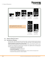
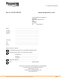

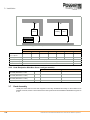
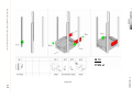
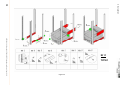
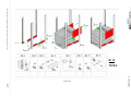
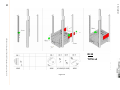

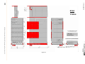
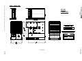

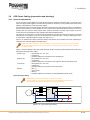
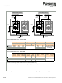
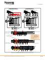
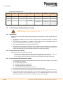

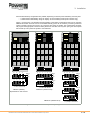
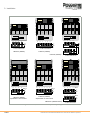
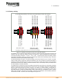
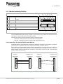
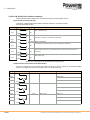
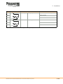

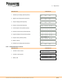
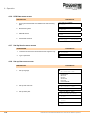


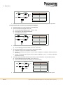
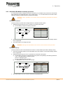
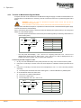
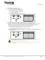
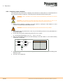

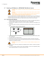
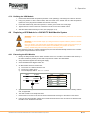


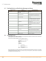
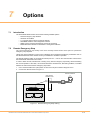
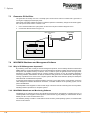
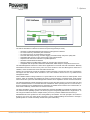
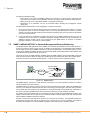
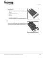
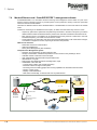
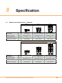
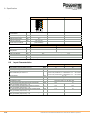
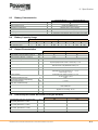
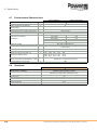
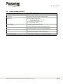
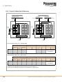

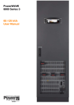
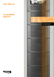

![G2 Decoder [obsolete] Second Generation User Manual](http://vs1.manualzilla.com/store/data/005963661_1-2c18e92993151caf68904a7a924089ff-150x150.png)

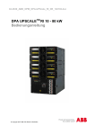

![AWD10SS [obsolete] User Manual](http://vs1.manualzilla.com/store/data/005777265_1-bc3e4afb4b891fb2fe3c32a930faa0e5-150x150.png)