1
PlugIn
IPEmotion PlugIn
IPETRONIK LOG
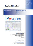
User manual
March 2010
All rights reserved!
Content
Content
Content .........................................................................................2
1 Important information ............................................................4
1.1
Liability, Warranty, Copyright, License agreement.................................................... 4
1.1.1 Limitation of liability ................................................................................................ 4
1.1.2 Warranty................................................................................................................. 4
1.1.3 Copyright and Duplication...................................................................................... 4
1.1.4 Software license agreement .................................................................................. 4
2 General information ...............................................................6
2.1
2.2
2.2.1
2.2.2
2.2.3
2.3
2.4
2.5
2.5.1
2.5.2
2.5.3
2.6
About this manual ...................................................................................................... 6
Version....................................................................................................................... 6
User manual IPEmotion PlugIn IPETRONIK LOG................................................. 6
IPEmotion PlugIn IPETRONIK LOG ...................................................................... 6
IPEmotion............................................................................................................... 6
Legend of the used icons .......................................................................................... 6
Support ...................................................................................................................... 7
Related documentations............................................................................................ 7
IPEmotion............................................................................................................... 7
Manual MAL development ..................................................................................... 7
Logger manual ....................................................................................................... 7
Documentation feedback........................................................................................... 8
3 Introduction ..........................................................................10
4 Setting up and removing .....................................................12
4.1
System requirements............................................................................................... 12
4.1.1 Hardware.............................................................................................................. 12
4.1.2 Platforms .............................................................................................................. 12
4.2
Installing IPEmotion PlugIn IPETRONIK LOG ........................................................ 13
4.3
Uninstalling IPEmotion PlugIn IPETRONIK LOG .................................................... 17
5 Working with IPEmotion PlugIn IPETRONIK LOG.............19
5.1
Defining general settings ......................................................................................... 19
5.2
Defining components............................................................................................... 26
5.2.1 Defining additional components........................................................................... 27
M-LOG and S-LOG ......................................................................................................... 27
M-LOG (6 CAN – 2 LIN).................................................................................................. 33
FLEETlog ........................................................................................................................ 33
IPEmotion PlugIn IPETRONIK LOG
IPETRONIK GmbH & Co. KG
2/ 41
Content
Import function ................................................................................................................ 34
5.3
Defining channels .................................................................................................... 35
5.3.1 CAN input “IPETRONIK CAN” and “Standard CAN” ........................................... 35
Status .............................................................................................................................. 35
CAN channel................................................................................................................... 36
5.3.2 COM-2 connector “COM-2”.................................................................................. 38
GPS................................................................................................................................. 38
5.3.3 Data processing “Local calculations” ................................................................... 39
Calculation ...................................................................................................................... 39
5.3.4 Data processing “Statistic” ................................................................................... 40
Classification................................................................................................................... 40
IPEmotion PlugIn IPETRONIK LOG
IPETRONIK GmbH & Co. KG
3/ 41
Important information
1 Important information
Please follow these instructions before and during the use and application of any
IPETRONIK product!
1.1 Liability, Warranty, Copyright, License agreement
1.1.1 Limitation of liability
Any liability of IPETRONIK, its representatives, agents and the like, especially with regard to
personal injury or damage to property of any kind, shall be excluded (within the legally
admissible framework), as far as, the instructions and warnings, as mentioned below, have
not been followed.
1.1.2 Warranty
Products, accessories and services have a 12 months warranty.
All product data, specifications, drawings, etc., correspond to the current condition of the
indicated creation date. For the purpose of optimizing technical processes and production,
some details of our modules and accessory components may be modified at any time
without prior notification.
Although the present document has been prepared with the utmost attention to detail, it may
not be exempt of misprints, typing or transcription errors. These errors are not covered by
any warranty.
1.1.3 Copyright and Duplication
We reserve all rights, in particular those of property, copyright and trademarks. The rights
related to any third party trademarks mentioned in the present document remain unaffected.
This document may not be duplicated, partially or entirely without the prior approval from
IPETRONIK GmbH & Co. KG. All graphics and explanations are copyright protected. Any
use beyond the scope of the document is prohibited.
1.1.4 Software license agreement
IMPORTANT: THIS IS A LEGAL AGREEMENT BETWEEN YOU, LICENSEE, AND
IPETRONIK GMBH & CO. KG/IPETRONIK INC. ("IPETRONIK"). BY CHECKING “I ACCEPT
ALL OF THE TERMS CONTAINED IN THE ABOVE AGREEMENT” DURING
INSTALLATION, COPYING OR USING THIS PRODUCT IN ANY WAY YOU
ACKNOWLEDGE THAT YOU HAVE READ THIS LICENSE AND THAT YOU
UNDERSTAND AND EXPRESSLY AGREE TO BE BOUND BY THE TERMS AND
CONDITIONS SET FORTH BELOW.
This software is property of IPETRONIK GmbH & Co. KG, and is protected by copyright
laws. Its total or partial reproduction is strictly forbidden.
IPEmotion PlugIn IPETRONIK LOG
IPETRONIK GmbH & Co. KG
4/ 41
Important information
The following actions are allowed:
Installing and using a copy of the product on a single computer or network. This
copy may only be used by a single user at a time. If the product is to be used by
multiple users, an additional license will be required for each user.
Creating a copy of the product for filing or backup purposes.
Using a copy of the product on a home computer or on a portable computer,
provided that the copy is not installed at the same time also on your main
computer.
Transferring the product to another person is only permitted, if the license rights
are also transferred, and if the product and any copies created are completely
deleted or erased (including copies on hard drives), and if the new owner agrees
with the requirements of this license.
IPEmotion PlugIn IPETRONIK LOG
IPETRONIK GmbH & Co. KG
5/ 41
General information
2 General information
2.1 About this manual
The manual IPEmotion PlugIn IPETRONIK LOG describes the structure of the PlugIn and
how to use the features for configuring devices, which are based on the IPETRONIK CAN
driver, in IPEmotion, taking acquisitions and managing and analyzing the resulting data.
Please read the manual IPEmotion PlugIn IPETRONIK LOG carefully to get to know the
operating and to learn more about the functions and special features. This manual also
contains information for installing and removing the software.
2.2 Version
2.2.1 User manual IPEmotion PlugIn IPETRONIK LOG
This manual has the version number 01.03.
2.2.2 IPEmotion PlugIn IPETRONIK LOG
The descriptions in this documentation refer to the current release with the version number
03.20.
2.2.3 IPEmotion
The descriptions in this documentation refer to the current release with the version number
01.03.
The PlugIn requires at least IPEmotion V01.00 on your computer.
2.3 Legend of the used icons
Tip
This icon indicates a useful tip that facilitates the application
of the software.
Information
This icon indicates additional information for a better
understanding.
IPEmotion PlugIn IPETRONIK LOG
IPETRONIK GmbH & Co. KG
6/ 41
General information
Attention!
This icon indicates important information to avoid potential
error messages.
2.4 Support
Headquarter:
IPETRONIK GmbH & Co. KG
Jägerweg 1
76532 Baden-Baden, Germany
Phone +49 72 21 99 22 0
Fax +49 72 21 99 22 100
[email protected]
www.ipetronik.com
Limited commercial partnership with its head office in Baden-Baden, registry court HRA No.
201313
IPETRONIK Verwaltungs GmbH Baden-Baden is an individually liable society,
registry court Mannheim HRB No. 202089
Management: Erich Rudolf, Andreas Wocke
Technical support and product information
www.ipetronik.com
e-mail: [email protected]
2.5 Related documentations
2.5.1 IPEmotion
The documentation IPEmotion.pdf provides you with a description and useful information
related to IPEmotion. This documentation is stored in the following standard language
dependent directory: C:\Programs\IPETRONIK\IPEmotion Vxx.xx.xx\Help.
2.5.2 Manual MAL development
The documentation MAL development.pdf provides you with a description and useful
information related to the use of the interface with plug-in components and IPEmotion.
2.5.3 Logger manual
The documentation Logger_Manual.pdf provides you with a description and useful
information related to the IPETRONIK M- and S-LOG devices.
IPEmotion PlugIn IPETRONIK LOG
IPETRONIK GmbH & Co. KG
7/ 41
General information
2.6 Documentation feedback
At IPETRONIK, the technical publications team strives to produce documentations of the
highest quality and values your feedback as a reader and user. If you have any comments or
suggestions regarding our product manuals, contact us under [email protected].
IPEmotion PlugIn IPETRONIK LOG
IPETRONIK GmbH & Co. KG
8/ 41
General information
Please inform us about the following points:
Version number (Select Options → PlugIns from the menu to display the version
number.),
Name of the guide,
Page number or section title,
Brief description of the content (e.g. inaccurate instructions, grammatical errors, or
information that require clarification),
Any suggestions for a general documentation improvement.
IPEmotion PlugIn IPETRONIK LOG
IPETRONIK GmbH & Co. KG
9/ 41
Introduction
3 Introduction
The IPETRONIK LOG PlugIn offers you the ability to use M-, S-LOG, and FLEETlog devices
of IPETRONIK within IPEmotion.
The systems of the IPETRONIK LOG System are separated into the following three groups
according to their functionality:
M-LOG
S-LOG
FLEETlog
Each single system of loggers contains different devices, which can be used for acquiring
data. Each device is an independent acquisition system and can be used as a stand-alone
devices, as well as, in combination with other devices in a CAN bus network. The current
IPEmotion PlugIn IPETRONIK LOG version offers the following devices (they are listed
accordingly to the above system classification):
M-LOG:
M-LOG (2 CAN)
M-LOG (4 CAN)
M-LOG (8 CAN)
M-LOG (6 CAN - 2 LIN)
M-LOG (8 CAN - 4 LIN)
M-LOG (4 CAN - 2 ETH)
M-LOG (8 CAN - 2 ETH)
M-LOG (6 CAN - 2 LIN – 2 ETH)
M-LOG (4 CAN - 2 ETH – 1 DIG I/O)
S-LOG:
S-LOG (2 CAN)
S-LOG (4 CAN)
S-LOG (8 CAN)
S-LOG (6 CAN - 2 LIN)
IPEmotion PlugIn IPETRONIK LOG
IPETRONIK GmbH & Co. KG
10/ 41
Introduction
FLEETlog:
FLEETlog basic (4 CAN)
FLEETlog WAN (4 CAN)
Please note that FLEETlog basic does not support a connection by using WiFi and
modem and a use of a GPS device is not possible!
Each single device provides additional components, as well as, a variety of channels. The
following chapter 5 shows an overview about the device-specific components and their
configuration.
Please find detailed information about the M- and S-LOG devices of
IPETRONIK in the documentation Logger_Manual.
IPEmotion PlugIn IPETRONIK LOG
IPETRONIK GmbH & Co. KG
11/ 41
Setting up and removing
4 Setting up and removing
4.1 System requirements
The minimum hardware and platform requirements for the application of the IPEmotion
PlugIn IPETRONIK LOG are outlined below.
4.1.1 Hardware
The minimum hardware requirements correspond to those of IPEmotion.
4.1.2 Platforms
The IPEmotion PlugIn IPETRONIK LOG can be run under the following operating systems:
Windows XP (32 Bit),
Windows Vista (32 Bit).
IPEmotion PlugIn IPETRONIK LOG
IPETRONIK GmbH & Co. KG
12/ 41
Setting up and removing
4.2 Installing IPEmotion PlugIn IPETRONIK LOG
The following chapter guides you through the installation process of the IPETRONIK LOG
PlugIn.
IPEmotion PlugIn IPETRONIK LOG needs administrator rights during the
installation. For working with the PlugIn you need at least limited user’s or
default user’s rights (Vista).
The installation of IPEmotion PlugIn IPETRONIK LOG is based on an installation wizard that
guides you through the setup process step by step. You can start the installation wizard from
the USB flash drive or, if you have downloaded the setup program from the IPEmotion forum
at www.ipemotion.com, from the setup file itself.
To install IPEmotion PlugIn IPETRONIK LOG:
1. Start the installation wizard from the USB flash drive or from the setup file.
USB flash drive: Connect the USB flash drive to the USB port of your computer and
follow the instructions of the installation wizard.
Setup file: Browse the location of the setup file and double-click IPEmotion PlugIn
IPETRONIK LOG.exe to start the installation wizard.
Depending on the used PC operating system, a security warning appears.
Click Run to start the installation wizard.
2. Setup language/Setup-Sprache/Langue d’installation: Select the language for the
installation process. You can choose between the languages German (Germany), English
(USA), and French (France).
Click OK to start the IPETRONIK LOG installation wizard.
IPEmotion PlugIn IPETRONIK LOG
IPETRONIK GmbH & Co. KG
13/ 41
Setting up and removing
3. Welcome screen: This is the first screen in the IPEmotion PlugIn IPETRONIK LOG
installation wizard.
Click Next to continue.
4. Destination folder:
Due to the security model of Microsoft Corporation related to .NET
applications, the installation of IPEmotion PlugIn IPETRONIK LOG on a local
drive is recommended.
According to the Microsoft conformance guidelines for Windows applications
the files are installed to the default locations that are specific to the operating
system and language.
Accept the default installation location for IPEmotion PlugIn IPETRONIK LOG. To select
another location click Change.
IPEmotion PlugIn IPETRONIK LOG
IPETRONIK GmbH & Co. KG
14/ 41
Setting up and removing
After you have specified the location for the installation, click OK to return to the Destination
folder screen.
Click Next to continue.
5. Ready to install the program: This screen indicates that IPEmotion PlugIn IPETRONIK
LOG is ready to install.
Click Install to start the installation.
IPEmotion PlugIn IPETRONIK LOG
IPETRONIK GmbH & Co. KG
15/ 41
Setting up and removing
6. Installing: A progress bar is shown during the installation process.
7. InstallShiel Wizard Completed: After the successful installation, the following screen is
shown.
Click Finish to exit the installation wizard.
A Windows-Silent-Setup cannot run other setups in silent mode, the plugin must
therefore be installed as silent, too:
Setup IPEmotion PlugIn IPETRONIK LOG.exe /S /v/qn
LOGGER plugin setup copies LOG2PC-Core into Temp directory and installs
LOG2PC-Core in Silent mode, which must also be installed separately:
Setup LOG2PC Core.exe /S /v/qn
IPEmotion PlugIn IPETRONIK LOG
IPETRONIK GmbH & Co. KG
16/ 41
Setting up and removing
4.3 Uninstalling IPEmotion PlugIn IPETRONIK LOG
The following chapter shows the deinstallation process of IPEmotion PlugIn IPETRONIK
LOG.
For removing IPEmotion PlugIn IPETRONIK LOG you have two possibilities:
The option Remove of the IPEmotion PlugIn IPETRONIK LOG installation program
The option Add or Remove Programs for IPEmotion PlugIn IPETRONIK LOG in
the Control Panel.
With both methods you can remove files, folders and registry entries from your computer,
which has been created during the installation.
Removing IPEmotion PlugIn IPETRONIK LOG with the installation program
To do so, proceed as follows:
1. Click in the menu Start on your computer on Settings and then Control Panel.
2. Double-click in the Control Panel on Add or Remove Programs.
3. Select from the program list the entry IPEmotion PlugIn IPETRONIK LOG and click
Change to start the installation wizard.
Click Next to advance to the Program maintenance screen.
4. Program maintenance: This screen allows you to modify, repair or remove IPEmotion
PlugIn IPETRONIK LOG. Select Remove and click Next to continue.
IPEmotion PlugIn IPETRONIK LOG
IPETRONIK GmbH & Co. KG
17/ 41
Setting up and removing
5. Remove the program: This screen indicates that your installation is now ready to
remove. Click Remove to start the removing process.
6. Uninstalling: A progress bar is shown during the uninstalling process.
7. InstallShiel Wizard Completed: This screen is shown after the successful deinstallation.
Click Finish to exit the installation wizard.
After removal, IPEmotion PlugIn IPETRONIK LOG is no longer indicated in the program list.
Removing IPEmotion PlugIn IPETRONIK LOG with the deinstallation function of the
Control Panel
To do so, proceed as follows:
1. Click in the menu Start on your computer on Settings and then Control Panel.
2. Double-click in the Control Panel on Add or Remove Programs.
3. Select from the program list the entry IPEmotion PlugIn IPETRONIK LOG and click
Remove to start the installation wizard.
4. Click Yes to start the deinstallation.
5. A progress bar is shown during the uninstalling process.
After the successful removal of IPEmotion PlugIn IPETRONIK LOG, the program has been
removed from your computer and is no longer indicated in the program list.
IPEmotion PlugIn IPETRONIK LOG
IPETRONIK GmbH & Co. KG
18/ 41
Working with IPEmotion PlugIn IPETRONIK LOG
5 Working with IPEmotion PlugIn
IPETRONIK LOG
The following chapter offers an overview of the available commands and their functions. In
addition, it is shown how to use the IPETRONIK LOG devices and the software IPEmotion
for configuring and acquiring data, as well as, managing and analyzing the acquired data.
5.1 Defining general settings
The main navigation tab Signals contains all available and connected systems with the
respective type description and channels. Click on the button Add system or Add component
to expand the configuration by further systems or components.
To define the general settings for the system properties, proceed as follows:
Please find detailed information about the functionality and meaning of the
following IPEmotion parameters in the IPETRONIK documentation
IPEmotion: General.
Select in the left tree view the desired system. You can find the Extended tab in the
window of the configuration dialog. You can set the following configuration definitions:
Front number
The front number defines the last digits of the device number. It refers to the last five
digits of the serial number by default. The serial number is mandatory for detecting,
using, and distinguishing the device from others within IPEmotion. The serial number
is composed of the front number and the device type and can generally be found at
the back of the device or is detected automatically in IPEmotion.
IPEmotion PlugIn IPETRONIK LOG
IPETRONIK GmbH & Co. KG
19/ 41
Working with IPEmotion PlugIn IPETRONIK LOG
TESTdrive version
The TESTdrive version shows the current version of the TESTdrive software.
Additional file
Define an additional file for the export.
The System tab offers the following configuration possibilities:
Switch-on condition (WakeonCan)
Activate or deactivate the Wake on Can function and define the switching-on of the
logger due to data traffic on the bus.
Timeout
The timeout defines the seconds to send an alternate value if no message is received
on the bus.
New measuring file
Activate or deactivate the use of a new measuring file number, which defines the
beginning for the serial data numeration.
Start with number
Define the number for beginning the serial numeration.
Follow-up time
The follow-up time defines the extension of acquiring data in the acquisition mode by x
seconds. The minimum and standard value is set to 10 s.
COMgate switch-on condition
Cyclical data saving
By using the Data manager tab you have the ability to select the following
properties:
Data remote transmission
Activate or deactivate transmitting the acquired data.
Compress files
Activate or deactivate creating a zip file. Due to a smaller file size, you can use a safe
and fast data transfer and an optimum utilization of the memory space.
IPEmotion PlugIn IPETRONIK LOG
IPETRONIK GmbH & Co. KG
20/ 41
Working with IPEmotion PlugIn IPETRONIK LOG
Split files
Activate or deactivate the partitioning of the acquisition file into smaller files of 500 kB
each.
Take measuring file into configuration
Activate or deactivate the integration of the configuration file ‘.isf into the acquisition
file and allow a better assignation and analysis of the data to the used configuration.
Take log file into configuration
Activate or deactivate the LOG file integration into the measurement file.
Use ping
By using the Configuration button you have the ability to open the Data transfer
configuration dialog and to define the following settings:
The General tab offers the following configuration possibilities:
Emergency switch-off after
The emergency switch-off defines the maximum time of the data transfer in min/h.
After the lapse of the predefined time, a forced disconnection is activated, e.g. due
to a bad transferring quality.
File encoding
Activate or deactivate the password protected locking of the created zip file.
Password – File encoding
Define a user-specific password for the zip file.
FTP upload
Activate or deactivate the use of the FTP server for the data transfer and storage.
Time synchronization via SNTP
Activate or deactivate the use of the time synchronization and define the SNTP
server IP address. The SNTP server IP (Simple Network Time Protocol) defines
the local time server for the automatic setting of the logger system time accordingly
to the time of the used system.
By using the FTP server tab you have the ability to select the following
properties:
IPEmotion PlugIn IPETRONIK LOG
IPETRONIK GmbH & Co. KG
21/ 41
Working with IPEmotion PlugIn IPETRONIK LOG
Server name
The server name address defines the FTP server name for the data transfer to
the FTP server.
IP address
The server IP address defines the FTP server address for the data transfer to
the FTP server.
User name
The user name defines the set user name for the data transfer to the FTP
server.
Password
The password defines the required password for using the FTP connection for
the data transfer to the FTP server.
Directory
The directory defines the location for the data transfer and storage on the FTP
server.
The Media selection tab offers the following possibilities for transferring data:
LAN/WiFi
By using the LAN/WIFI tab you can define the following settings:
Get IP address automatically
Activate or deactivate the DHCP function (Dynamic Host Configuration Protocol)
for the automatic assignation of the IP address, sub net mask and standard
gateway.
IP address
The IP address defines the static system IP address for the data transfer.
Sub net mask
The sub net mask defines the net address, which is also used by the
communication partner.
Standard gateway
The standard gateway defines the address of a potential router between the
communication partners.
IPEmotion PlugIn IPETRONIK LOG
IPETRONIK GmbH & Co. KG
22/ 41
Working with IPEmotion PlugIn IPETRONIK LOG
If you activated the “Use of DHCP” function, the IP address, sub
net mask and standard gateway are automatically assigned.
Preferred DNS server and Alternative DNS server
Define the server for the name conversion.
This function is only required if the FTP server is identified by using
a name. In this case, the DNS server converts the name into an IP
address. If the FTP server is directly identified by using the IP
address, the entry of the DNS server is not required.
Speed and duplex mode
The media type defines the speed of the interface connection.
Modem
By using the Modem tab you can define the following settings:
Model
The modem defines the used connection on the logger for the data transfer.
PIN code
The PIN defines the PIN of the used SIM card.
Authentication
Activate or deactivate the authentication. The authentication is provider
dependent and defines the user identity check depending on the used SIM card.
User name
The user name is provider dependent and defines the set user name depending
on the used SIM card.
Password
The password is provider dependent and defines the required password for using
the connection depending on the used SIM card.
Access point (APN)
The access point name is provider dependent and defines the name for the
access point to a connection depending on the used SIM card.
IPEmotion PlugIn IPETRONIK LOG
IPETRONIK GmbH & Co. KG
23/ 41
Working with IPEmotion PlugIn IPETRONIK LOG
COMgate
By using the COMgate transfer tab you can define the following settings:
Hotspot
Modem (3G/HSPA/UMTS)
Activate the used connection on the logger for the data transfer.
The COMgate – Modem tab offers the following configuration possibilities:
PIN code
The PIN defines the PIN of the used SIM card.
Authentication
Activate or deactivate the authentication. The authentication is provider
dependent and defines the user identity check depending on the used SIM card.
User name
The user name is provider dependent and defines the set user name depending
on the used SIM card.
Password
The password is provider dependent and defines the required password for
using the connection depending on the used SIM card.
Access point (APN)
The access point name is provider dependent and defines the name for the
access point to a connection depending on the used SIM card.
Wireless LAN (WiFi)
Activate the used connection on the logger for the data transfer and select the
preferred connection type (WiFi, 3G/HSPA/UMTS).
The COMgate - WiFi tab offers the following configuration possibilities:
SSID
Security
Password
The password is provider dependent and defines the required password for
using the connection depending on the used SIM card.
IPEmotion PlugIn IPETRONIK LOG
IPETRONIK GmbH & Co. KG
24/ 41
Working with IPEmotion PlugIn IPETRONIK LOG
Certificate
DHCP
Activate or deactivate the DHCP function (Dynamic Host Configuration
Protocol) for the automatic assignation of the IP address, sub net mask and
standard gateway.
IP address
The IP address defines the static system IP address for the data transfer.
Sub net mask
The sub net mask defines the net address, which is also used by the
communication partner.
Standard gateway
The standard gateway defines the address of a potential router between the
communication partners.
If you activated the “Use of DHCP” function, the IP address, sub
net mask and standard gateway are automatically assigned.
Preferred DNS server
Alternative DNS server
IPEmotion PlugIn IPETRONIK LOG
IPETRONIK GmbH & Co. KG
25/ 41
Working with IPEmotion PlugIn IPETRONIK LOG
5.2 Defining components
Each logger contains a variety of functions according different in- and outputs, connectors
and the data processing in the logger.
To define the general settings for the logger properties, proceed as follows:
Please find detailed information about the functionality and meaning of the
following IPEmotion parameters in the IPETRONIK documentation
IPEmotion: General.
Select in the left tree view the desired component.
The CAN input of a logger offers additional definition possibilities.
You can find the CAN tab in the window of the configuration dialog. You have the
ability to select the following properties:
Baud rate
The baud rate defines the transfer rate, which is valid for all system devices, for
communicating to the devices.
29-bit identifier
Activate or deactivate the extension of the address range from 11 bit to 29 bit.
IPEmotion PlugIn IPETRONIK LOG
IPETRONIK GmbH & Co. KG
26/ 41
Working with IPEmotion PlugIn IPETRONIK LOG
Acknowledge
Activate or deactivate the Acknowledge function to confirm the reception of a correct
CAN message.
By using the Timeout tab you can activate or deactivate the use of a timeout. The
timeout defines the seconds to send an alternate value if no message is received on the
bus.
The ETH input of a logger can be defined within the ETH input tab.
The LIN input of a logger offers additional definition possibilities, too.
By using the LIN tab you have the ability to select the following properties:
Baud rate
The baud rate defines the transfer rate, which is valid for all system devices, for
communicating to the devices.
LIN version
The LIN version shows the current version of the LIN bus.
By using the Timeout tab you can activate or deactivate the use of a timeout. The
timeout defines the seconds to send an alternate value if no message is received on the
bus.
5.2.1 Defining additional components
M-LOG and S-LOG
The following overview shows all possible component-dependent functionalities of the Mand S-LOG (2 CAN), (4 CAN), (8 CAN). The respective loggers only differ in the number of
CAN inputs.
Click on the button Add component to expand the configuration by further components or
functions.
Please find detailed information about the functionality and meaning of the
following IPEmotion parameters in the IPETRONIK documentation IPEmotion:
General.
IPEmotion PlugIn IPETRONIK LOG
IPETRONIK GmbH & Co. KG
27/ 41
Working with IPEmotion PlugIn IPETRONIK LOG
By using the CAN input tab you can define the following settings:
Status
Define status channels for controlling the connected devices and the data transfer.
IPETRONIK CAN
Voltage/current
Temperature
Pressure
IPEmotion PlugIn IPETRONIK LOG
IPETRONIK GmbH & Co. KG
28/ 41
Working with IPEmotion PlugIn IPETRONIK LOG
Edge counting
Define in the window of the configuration dialog the following additional settings:
Initialize devices, Synchronized mode, Automatic CAN ID placing.
Please find detailed information on the definition of IPETRONIK CAN in
the IPETRONIK manual IPEmotion PlugIn IPETRONIK CAN.
Standard-CAN
CAN channel
CAN send
Channels
Please note that at least one channel must be activated on the logger for
adding channels! This can be an input, output or a calculated channel.
Define in the window of the configuration dialog the following additional settings:
Sending frequency, First CAN ID, Time stamp.
The sending frequency defines the updating rate for reading the data on the bus.
The first CAN ID defines the first identifier for sending the first message. You can convert
the CAN ID into the decimal, hexadecimal or binary system.
d – Decimal system
h – Hexadecimal system
b – Binary system
Activate or deactivate creating a time stamp channel. The time stamp defines a value,
which assigns an event to a point of time.
Traffic recording
Traffic filter
ID-Trigger
Define in the window of the configuration dialog the following additional settings: Quick
start. For the Traffic filter you can set the first and last CAN ID. The ID-Trigger contains
the definition of the CAN-ID and the bytes 1-8.
IPEmotion PlugIn IPETRONIK LOG
IPETRONIK GmbH & Co. KG
29/ 41
Working with IPEmotion PlugIn IPETRONIK LOG
Activate or deactivate the Quick start. Allow a quick initialization of the devices.
The ID-Trigger defines the trigger conditions for controlling the data acquisition. The IDTrigger is set, if a message with the corresponding CAN-ID, e.g. 10, reaches a defined
value on the corresponding byte, e.g. Byte 1 = 200.
The CAN input offers you the ability to import CANdb, A2L or IDF files.
Please find detailed information on the import function in the IPETRONIK
documentation IPEmotion.
By using the extended ETH 01/02 port tab you can define the following settings:
Extender (4 CAN)
Define in the window of the configuration dialog the CAN parameters above and set local
calculations.
For the DIG I/O port you can define the following settings:
Powermanagement
POWER OUT 01 - 08
Define for the POWER OUT channels in the window of the configuration dialog
additional settings like the Start, On, Off behavior. The Start behavior tab contains
the start delay. The On behavior tab contains the definitions Criterion, Only active at
PowerGood, Minimum duration, Delay, Priority. The Off behavior tab contains the
definitions Criterion, Off at PowerBad, Minimum duration.
By using the USB port tab you can define the following settings:
Camera
Video recording
Image recording
Define for the Video recording in the window of the configuration dialog additional
settings like the Resolution, Rate in images/s, and the Maximum recording time in
s/min/h, as well as, the Trigger. For the Image recording you can define settings
according the Resolution and set the Trigger.
The Trigger defines conditions for controlling the data acquisition. The trigger
conditions can be deduced from acquired signals, as well as, from calculated
channels.
By using the ETH port tab you can define the following settings:
XCP service
DAQ-List 1 Hz
DAQ-List 10 Hz
IPEmotion PlugIn IPETRONIK LOG
IPETRONIK GmbH & Co. KG
30/ 41
Working with IPEmotion PlugIn IPETRONIK LOG
DAQ-List 100 Hz
Please note that at least one channel must be activated on the logger for
adding channels! This can be an input, output or a calculated channel.
Define in the window of the configuration dialog the following additional XCP settings IPAddress and IP-Port and the extended settings MAX_ODT and MAX_ODT_ENTRIES.
The IP-Address defines the IP address of the target system for the XCP data transfer.
The IP-Port defines the port of the target system for the XCP data transfer.
By using the COM-2 port tab you can define the following settings:
GPS
Define in the window of the configuration dialog the following additional settings: Baud
rate.
The baud rate defines the transfer rate for communicating to the devices.
By using the Audio port tab you can define the following settings:
Audio recording
Audio output
Define for the Audio recording in the window of the configuration dialog additional
settings like the Bit rate and the Maximum recording time in s/min/h, as well as, the
Trigger. For the Audio output you can define settings according the Audio file and an
Immediate stop at stop trigger, as well as, set the Trigger.
The bit rate defines the amount of data, which is transferred within a specific time.
The audio file for the audio output can be stored in a user defined directory in the *.wav
format.
Activate or deactivate the Immediate stop at stop trigger function for stopping the audio
output immediately if a stop trigger is activated.
The Trigger defines conditions for controlling the data acquisition. The trigger conditions
can be deduced from acquired signals, as well as, from calculated channels.
By using the Display port tab you can define the following settings:
M-VIEWfleet
M-VIEWgraph
M-VIEWvga
IPEmotion PlugIn IPETRONIK LOG
IPETRONIK GmbH & Co. KG
31/ 41
Working with IPEmotion PlugIn IPETRONIK LOG
Define for the M-VIEWfleet, as well as, for the M-VIEWgraph in the window of the
configuration dialog additional Mode settings like the scrolling mode and the list type.
Activate or deactivate the following commands: Allow start and stop of the acquisition,
Merge measurement files, Confirm shift/track at stop.
Connect the M-VIEWvga with the logger by using the standard monitor port and define
the buzzer and the monitor switch.
By using the Data processing tab you can define the following settings:
Status
Local storage groups
Storage group
Ring buffer group
The settings for the storage group contain the Time stamp channel, NoValues and
Save trigger channel. The Triggering contains definition possibilities according the
Mode, the Pre- and Post-trigger duration in s and the Start- and Stop-trigger. The
storage rate can be defined independently per channel.
The storage rate defines one rate for all signals for recording and storing the data.
Activate or deactivate creating a time stamp channel. The time stamp channel defines
a channel in the corresponding storage group, which is configured for using a time
stamp. The time stamp defines a value, which assigns an event to a point of time.
Activate or deactivate reading NoValues. A NoValue defines an invalid value. You can
distinguish between a –Fullscale and an error in the dataset and ensure that the
acquisition file has no gaps in the time channel.
Activate or deactivate the Save trigger channel function. This function defines the
saving of the trigger status, as well as, additional information in a channel of the
corresponding storage group.
The Triggering defines conditions for controlling the data acquisition. The trigger
conditions can be deduced from acquired signals, as well as, from calculated
channels.
Please note that at least one channel must be activated on the logger for
adding channels! This can be an input, output or a calculated channel.
Local calculations
Calculation
IPEmotion PlugIn IPETRONIK LOG
IPETRONIK GmbH & Co. KG
32/ 41
Working with IPEmotion PlugIn IPETRONIK LOG
The sampling rates of the calculations can be configured.
Statistic
Classification
For the Statistic you can define settings according the Resetting behavior and he
Working frequency and set the Trigger.
The Working frequency defines the speed of the statistic generation.
The settings for the classification contain the Mode. The Trigger contains definition
possibilities according the Mode and Formula.
The mode defines the classification method.
The Trigger defines conditions for controlling the data acquisition. The trigger
conditions can be deduced from acquired signals, as well as, from calculated
channels.
Please note that at least one channel must be activated on the logger for
adding channels! This can be an input, output or a calculated channel.
M-LOG (6 CAN – 2 LIN)
By using the LIN input tab you can define the following settings:
Traffic recording
Traffic filter
ID-Trigger
Define in the window of the configuration dialog the following additional settings: Quick
start. For the Traffic filter you can set the first and last CAN ID. The ID-Trigger contains
the definition of the CAN-ID and the bytes 1-8.
Activate or deactivate the Quick start. Allow a quick initialization of the devices.
The ID-Trigger defines the trigger conditions for controlling the data acquisition. The IDTrigger is set, if a message with the corresponding CAN-ID, e.g. 10, reaches a defined
value on the corresponding byte, e.g. Byte 1 = 200.
FLEETlog
FLEETlog differs between the two systems FLEETlog Basic and FLEETlog WAN.
IPEmotion PlugIn IPETRONIK LOG
IPETRONIK GmbH & Co. KG
33/ 41
Working with IPEmotion PlugIn IPETRONIK LOG
The equipment and configuration possibilities of the FLEETlog Basic correspond to those of
a M-/S-LOG (4 CAN). The FLEETlog WAN additionally offers the possibility to directly add
the GPS component to the configuration.
Import function
Select a free CAN input.
Select Import from the tab menu or by using the context menu (right mouse button).
Select the desired import and define the directory of a description file for opening it.
The current version offers the following import possibilities:
CANdb (*.dbc file)
A2L (*.A2L file)
Diagnostics (*.idf file)
UDS (*.xml file)
Select the desired signals / CAN signals / channels in the left window (Available
channels).
IPEmotion PlugIn IPETRONIK LOG
IPETRONIK GmbH & Co. KG
34/ 41
Working with IPEmotion PlugIn IPETRONIK LOG
Enter the signals by using Drag&Drop into the right window (Included channels).
Select OK for accepting the selection.
5.3 Defining channels
5.3.1 CAN input “IPETRONIK CAN” and “Standard CAN”
Status
To define the settings for the channel properties, proceed as follows:
Please find detailed information about the functionality and meaning of the
following IPEmotion parameters in the IPETRONIK documentation
IPEmotion: General, Format, Scaling, Display.
Select in the right window of the channel view the desired channel. You can find the
Limit value tab in the window of the configuration dialog. You have the following
configuration possibilities:
Limit value controlling active
Activate or deactivate controlling the limit values. A limit value defines a required
upper and/or lower limit of a value.
Lower limit value
Upper limit value
Min-Max list
IPEmotion PlugIn IPETRONIK LOG
IPETRONIK GmbH & Co. KG
35/ 41
Working with IPEmotion PlugIn IPETRONIK LOG
Activate or deactivate the use of the Min-Max list. Define the creation of a text file *.txt,
where all defined global min and max values of the active channels are stored.
By using the NoValue tab you have the ability to select the following properties:
Value
A NoValue defines an invalid value. You can distinguish between a –Fullscale and an
error in the dataset and ensure that the acquisition file has no gaps in the time
channel.
Timeout
A timeout is generated at reaching the defined NoValue.
CAN channel
To define the settings for the channel properties, proceed as follows:
Please find detailed information about the functionality and meaning of the
following IPEmotion parameters in the IPETRONIK documentation
IPEmotion: General, Format, Scaling, Display.
Select in the right window of the channel view the desired channel. You can find the
CAN tab in the window of the configuration dialog. You can set the following definitions:
CAN ID
The CAN ID defines the identifier for sending the message. You can convert the CAN
ID into the decimal, hexadecimal or binary system.
d – Decimal system
IPEmotion PlugIn IPETRONIK LOG
IPETRONIK GmbH & Co. KG
36/ 41
Working with IPEmotion PlugIn IPETRONIK LOG
h – Hexadecimal system
b – Binary system
Start bit
The start bit defines the first bit in the message.
Bit count
The bit count defines the number of bits in the message.
Data format
The data format defines the message format. The standard format is “Intel”.
By using the Limit value tab you can define the following settings:
Limit value controlling active
Activate or deactivate controlling the limit values. A limit value defines a required
upper and/or lower limit of a value.
Lower limit value
Upper limit value
Min-Max list
Activate or deactivate the use of the Min-Max list. Define the creation of a text file *.txt,
where all defined global min and max values of the active channels are stored.
By using the NoValue tab you have the ability to select the following properties:
Value
A NoValue defines an invalid value. You can distinguish between a –Fullscale and an
error in the dataset and ensure that the acquisition file has no gaps in the time
channel.
Timeout
A timeout is generated at reaching the defined NoValue.
IPEmotion PlugIn IPETRONIK LOG
IPETRONIK GmbH & Co. KG
37/ 41
Working with IPEmotion PlugIn IPETRONIK LOG
5.3.2 COM-2 connector “COM-2”
GPS
To define the settings for the channel properties, proceed as follows:
Please find detailed information about the functionality and meaning of the
following IPEmotion parameters in the IPETRONIK documentation
IPEmotion: General, Format, Scaling, Display.
Select in the right window of the channel view the desired channel. You can find the
Limit value tab in the window of the configuration dialog. You have the following
configuration possibilities:
Limit value controlling active
Activate or deactivate controlling the limit values. A limit value defines a required
upper and/or lower limit of a value.
Lower limit value
Upper limit value
Min-Max list
Activate or deactivate the use of the Min-Max list. Define the creation of a text file *.txt,
where all defined global min and max values of the active channels are stored.
IPEmotion PlugIn IPETRONIK LOG
IPETRONIK GmbH & Co. KG
38/ 41
Working with IPEmotion PlugIn IPETRONIK LOG
By using the NoValue tab you have the ability to select the following properties:
Value
A NoValue defines an invalid value. You can distinguish between a –Fullscale and an
error in the dataset and ensure that the acquisition file has no gaps in the time
channel.
Timeout
A timeout is generated at reaching the defined NoValue.
5.3.3 Data processing “Local calculations”
Calculation
To define the settings for the channel properties, proceed as follows:
Please find detailed information about the functionality and meaning of the
following IPEmotion parameters in the IPETRONIK documentation
IPEmotion: General, Format, Display.
Select in the right window of the channel view the desired channel. You can find the
Formula tab in the window of the configuration dialog. Define a user-specific formula for
the calculation.
By using the Limit value tab you can define the following settings:
Limit value controlling active
Activate or deactivate controlling the limit values. A limit value defines a required
upper and/or lower limit of a value.
IPEmotion PlugIn IPETRONIK LOG
IPETRONIK GmbH & Co. KG
39/ 41
Working with IPEmotion PlugIn IPETRONIK LOG
Lower limit value
Upper limit value
Min-Max list
Activate or deactivate the use of the Min-Max list. Define the creation of a text file *.txt,
where all defined global min and max values of the active channels are stored.
By using the NoValue tab you have the ability to select the following properties:
Value
A NoValue defines an invalid value. You can distinguish between a –Fullscale and an
error in the dataset and ensure that the acquisition file has no gaps in the time
channel.
Timeout
A timeout is generated at reaching the defined NoValue.
5.3.4 Data processing “Statistic”
Classification
IPEmotion PlugIn IPETRONIK LOG
IPETRONIK GmbH & Co. KG
40/ 41
Working with IPEmotion PlugIn IPETRONIK LOG
To define the settings for the channel properties, proceed as follows:
Please find detailed information about the functionality and meaning of the
following IPEmotion parameters in the IPETRONIK documentation
IPEmotion: General.
Select in the right window of the channel view the desired channel. You can find the
Settings tab in the window of the configuration dialog. You have the following
configuration possibilities:
Class count
The class count defines the number of classification sections of a channel.
Hysteresis
The hysteresis defines a difference between 2 values. This additional switching
threshold is used for eliminating potential factors of interference, e.g. oscillations of
electronic circuits. A hysteresis only allows a new counting if the value falls below or
passes a defined value.
Lower limit
The lower limit defines the minimum limit value of the classification section of a
channel.
Upper limit
The upper limit defines the maximum limit value of the classification section of a
channel.
IPEmotion PlugIn IPETRONIK LOG
IPETRONIK GmbH & Co. KG
41/ 41