1
Profile Modeler
Profile Modeler
( A SuperControl Product )
-1-
Profile Modeler
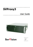
Index
Overview............................................................................................................................. 3
Terminology........................................................................................................................ 3
Launching the Application.................................................................................................. 4
File Menu............................................................................................................................ 4
Loading a File: ................................................................................................................ 4
To Load Multiple Files: .................................................................................................. 4
Clearing Loaded Files:.................................................................................................... 4
View Properties................................................................................................................... 5
Part Properties:................................................................................................................ 5
Rendering Detail: ............................................................................................................ 5
Rotate, Zoom, and Pan Multiplier: ................................................................................. 5
Reverse Zoom: ................................................................................................................ 5
Operation Menu ................................................................................................................. 6
Operation, Defaults ......................................................................................................... 6
Operation, Set Type ........................................................................................................ 6
Operation, Verify Tool Path ........................................................................................... 7
Operation, Reverse Tool Path ......................................................................................... 7
Operation, Edit Operation Tool ...................................................................................... 7
CNC, Write CNC:........................................................................................................... 7
Tooling Menu ..................................................................................................................... 8
Configuring Tools:.......................................................................................................... 8
Configuring Tool Groups:............................................................................................... 9
Part Tree List .................................................................................................................... 10
Viewing Parts.................................................................................................................... 11
Rotating:........................................................................................................................ 11
Panning: ........................................................................................................................ 11
Zooming:....................................................................................................................... 11
Fixed Views: ................................................................................................................. 11
Selecting a Region ............................................................................................................ 12
Region Specific Changes .................................................................................................. 13
Example Exercise ............................................................................................................. 14
-2-
Profile Modeler
Profile Modeler
Overview
The Profile Modeler is designed to take Thermwood Database files (from eCabinet
Systems) that contain parts with profile edge cuts created by the part editor and create
modeling type tool paths to produce these edges with standard modeling tools. A Custom
Tool option also exists so that a centerline path can be defined for cases that can be
machined in one pass with a custom shaped tool. These database files (*.twd) are created
when selecting the CNC Output feature from eCabinet Systems.
Terminology
There are a few terms that need to be defined to help better understand this application.
Region: An individual cut area on a part.
Tool Group: A group of tools used to machine a Region. A tool group can contain 1 or
more tools. Tools will be used in the order that they exist in the group.
Left Over: This is an area of a region that could not be machined by a tool. This is due
to the geometry of the tool not being able to clean out an area without violating the
finished parts shape.
Tool Marker: A representation of the cutting tool in the view area. If this option is
turned on, it will display a marker at the start point of each new tool path after a tool
change occurs.
-3-
Profile Modeler
Launching the Application
The Profile Modeler is an application that runs on the Thermwood SuperControl. The
application is launched from the main screen of the SuperControl by selecting F11
<THM Options> and then F5 <Profile Modeler>.
File Menu
Loading a File: Select <File>,
<Load> from the top menu and select a
.twd file. After the file desired is
selected, select <Open>. This file (if
containing profile edges) will now
appear in the part tree list on the left of
the dialog.
To Load Multiple Files: Multiple
files can be loaded together allowing
one CNC file to be written containing all
of the loaded parts. To load multiple
files, follow the load procedure listed
above and then select <File>, <Add>
and select another file to load then select
<Open>. Repeat this as many times as
needed.
Clearing Loaded Files: To clear all
files from the part list and start over,
Select <File>, <Clear All> from the top
menu.
-4-
Profile Modeler
View Properties
Select <View>, <Properties> from the main menu
Part Properties: This area allows color selection for the various display components.
Each display component can be turned on or off by having it checked or not checked.
Rendering Detail: Controls the level of detail used to display parts and tool paths.
The lower the setting the more faceted curved areas will appear. (This only affects the
view and will not decrease the accuracy of the actual CNC file output). This setting can
help improve the ability to rotate, zoom, and pan when inspecting parts that are large or
contain multiple curved paths.
Rotate, Zoom, and Pan Multiplier: Controls how responsive these options
respond to movements of the mouse.
Reverse Zoom: Controls the direction of the zoom function.
-5-
Profile Modeler
Operation Menu
Operation, Defaults
Select <Operation>, <Defaults>. These
settings mostly control user defaults for
the CNC programs.
General Defaults
Retract Height: This is how far above
the blank thickness the tool will retract
between each tool path. It is also the
initial height for the tool before
plunging into the work piece.
Tool Group: This is the tool group that will be used by default. This tool group can be
change on an individual region, but if not specifically changed, it will use the default for
all regions.
Custom Tool: This is the tool that will be used by default when using the custom tool
option. This tool can be change on an individual region, but if not specifically changed, it
will use this default.
CNC Offset
Manual: This will add manual offset code at the beginning of each part. If this option is
selected, a G51 X# Y# will be added at the beginning of each part (see the SuperControl
user manual for more information on the G51 code). This option would typically be used
if a random location on the machine will be used to cut the part(s).
Fixture: This will add a fixture Offset call at the beginning of each part. If this option is
selected, a G52L# will be added at the beginning of each part. (see the SuperControl user
manual for more information on the G52L# code). This option is the most common and
would typically be used if a common fence location on the machine will be used to cut
the part(s). If the fence location zero/origin point is not located in the corner of the blank
closest to machine Home, then it will be necessary to apply the X and/or Y Shift options
next to the fixture Offset selection. This will automatically adjust the fixture offset
relative to the parts blank size.
Operation, Set Type
Select <Operation>, <Set Type>.
This setting determines whether the
tool path for a region will be
modeled or if it will create a centerline path for a custom shaped tool.
-6-
Profile Modeler
Operation, Verify Tool Path
To activate this option, a region must
be selected. With a region chosen,
select <Operation>, <Verify Tool
Path>. This will graphically show the
tool path(s) as they will be performed
on the machine. The Show Tool Path
option must be check in the View,
Properties dialog before it will display in the view.
Operation, Reverse Tool Path
This option will change the starting location for the tool to the opposite side of the tool
path(s). Select a region and perform a Verify Tool Path, then select this option to reverse
the start location.
Operation, Edit Operation Tool
This option allows a tools cutting information to be modified individually per region. A
region must be selected and a tool highlighted in the tool display area in the lower left of
the dialog for this option to be activated. Changing the value via this menu will not
modify the default settings for the tool. It will only change the values for the highlighted
region.
CNC Menu
CNC, Write CNC: This will write
CNC code for all parts in the part tree
that are checked on. This feature will
automatically give the option to print
labels for the part(s). It is not required to load a part(s) in the view area to write a CNC
file for them. Parts can simply be loaded in the parts tree then select the Write CNC
option to use the default tool group for all regions.
-7-
Profile Modeler
Tooling Menu
Configuring Tools: To configure tools, select <Tooling>, <Tools> from the top
menu or select the Configure tools icon on the tool bar. Users must configure their tools
so that the Profile Modeler understands a tools characteristics.
A dialog with all tools that are currently
set up on the Thermwood SuperControl
will appear. Select the tool you wish to
configure and then select <Edit Tool>.
A Tooling Information
dialog will then appear.
Tool Type
Information: Here, the
type of tool, diameter,
flute length, and corner
radius (if set to
spherical) is set.
Tool Cutting
Information:
Max Penetration: is
the maximum depth
that the tool is allowed
to plunge into the work
piece. If the finished
depth is greater, the
tool path will be split
into as many depth
passes as needed.
-8-
Profile Modeler
Reverse Spindle: If checked, it will insert appropriate code to turn on the router spindle
for a left handed tool rotation (machine must be equipped with reverse spindle option).
Step Size: The amount the tool will step over between each machining pass.
Stock to Leave: The amount of stock that will be left beyond the finished edge of the
part when using this tool.
Feed Speed: The feed rate at which the tool will travel when machining a part.
Plunge Speed: The feed rate at which the tool will plunge into the part.
Spindle Speed: The RPM of the router spindle when using this tool.
Configuring Tool Groups:
To configure a tool group, select
<Tooling>, <Tool Groups> from the
top menu. A tool Group Setup dialog
will appear. To add a new group,
select the add tool group button and
type in a name and select OK. Next,
it will be necessary to add tools to
this new tool group. Select the tool group in the left hand column. If tools exist in the
selected group, they will show in the right column. Tools can be added, deleted, and
edited. The order that the tools exist in the list determines the order that they will be used
to machine the part. This order can be changed by selecting a tool in the right hand
column and then selecting the Raise or Lower priority buttons. To remove a tool group,
select the group name in the left hand column and select the Delete Tool Group button.
-9-
Profile Modeler
Part Tree List
The part tree list is located on the left side of the
Profile Modeler dialog. The tree is used for 2 major
purposes other than part information display. The
first is to select parts to be displayed in the view
area. To display a part in the view area, double click
on the part name in the tree. The second major use
for the tree is to filter out a part or parts from the
CNC file output. Notice the tree example to the
right. It has 3 database files loaded into it. The top
check box for each database is circled in the
example picture. Clicking on one of the green check
marks in the tree will turn it into a red X signifying
that this part will not be included in the CNC output.
If all parts in a given database are marked out, then a
Red X will show for each level of the tier. If some
but not all parts of a given database are marked out,
then a yellow background Exclamation mark will
show signifying that a partial list is marked out. If
desired, the tree list can be expanded to the right so
that more of the horizontal display is visible. To do
this, move the mouse over the Screen splitter bar until a double arrow is displayed for the
cursor, then click and drag to the left or right. Moving this can decrease the view area.
The scroll bar at the bottom of the tree view allows the view of the tree to be slide left
and right for viewing without expanding the tree view width. Also, hovering the mouse
over a tree view item will temporarily show the entire line.
Pops up when
hovered over
with mouse
Screen
Splitter
Bar
Horizontal
Scroll Bar
- 10 -
Profile Modeler
Viewing Parts
Viewing individual parts is not required to produce the CNC code. However, if it is
desired to see the results of a particular tool path for verification purposes it can be done.
To display parts in the view area, double click on the part name in the tree. The part can
now be rotated, zoomed, and panned. If multiple parts are chosen, there will be tabs along
the top of the view area that allow switching between the parts.
Rotating, Zooming, and Panning the Part
Once a part is loaded in the view area it can rotated, zoomed, and panned to better
analyze the part and or tool path. To perform these features, do the following:
Rotating:
a.) Hold down the Shift key and press and hold the Left mouse button.
b.) Or hold down the Shift key and select the Arrow Up, Down, Left, or Right keys.
Panning:
a.) Hold down the Shift key and press and hold the Right mouse button.
b.) Or hold down the Ctrl key and select the Arrow Up, Down, Left, or Right keys.
Zooming:
a.) Hold down the Shift key and press and hold Both mouse buttons.
b.) Or press the Minus or Plus keys on the keyboard.
Fixed Views:
The part view can also be switched directly to
any of the six fixed views by choosing the option
from the view menu. Select <View>, <Part
View>, and then select from one of the
following:
• Front View
• Back View
• Left View
• Right View
• Top View
• Bottom View
- 11 -
Profile Modeler
Selecting a Region
Once a part is loaded into the view area the various cutting regions will show. They can
be selected by clicking on them with the left mouse button. Regions can also be selected
by choosing the desired one in the region selection area on the left hand side of the
screen. When selected, the outline of the region will change to its selected color. If the
Show Region option in <View> <Properties> is not checked, you will need to be on the
outline of the region to select it with the mouse.
Cutting Regions
Region Selection Area
- 12 -
Profile Modeler
Region Specific Changes
There are several changes that can be made to individual regions that will not change
default settings that may work for most other parts or regions. With a region selected,
you can change:
¾ The start point of the tool paths
• After a Verify Tool Path has been performed on a region, select
<Operation>, <Reverse Tool Path> from the top menu or selecting the
Reverse Tool Path icon on the toolbar.
¾ The Tool or Tool Group used
• Select <Tooling>, <Set Tool/Tool Group> or select the Set Tool/Tool
Group icon on the tool bar. Select the Tool or Tool Group desired from the
list and then select OK. To graphically see the changes, a Verify Tool Path
must be performed again
¾ Tool Machining parameters
• Double click on a tool number displayed in the Tool Group/Custom Tool
display area in the lower left of the dialog or highlight the tool number
desired and select <Operation>, <Edit Operation Tool> from the top
menu. Make desired changes and then select OK. To graphically see the
changes, a Verify Tool Path must be performed again.
¾ Between Modeling or Custom Tool option
• Select <Operation>, <Set Type>, then <Model> or <Custom Tool> or
select between the Custom Tool or Model icon on the tool bar (these icons
are a toggle between the two modes). To graphically see the changes, a
Verify Tool Path must be performed again.
- 13 -
Profile Modeler
Example Exercise
The following exercise will walk through a sample part to help better understand the
Profile Modeler process.
Launch the Profile Modeler application from the main screen of the Thermwood
SuperControl by selecting F11 <THM Options> and then F5 <Profile Modeler>. We will
now set up some tools. For this example, we will need 3 tools and they will be tools 101,
102, and 103. You may use any tools that you want as long as they are set up to an
actuator and an actuator position. This simply means that these tools are assigned to a
cutting device on the machine. (reference the SuperControl user manual for more
information and proper use and setup of the tool management settings) Select
<Tooling>, <Tools> from the top menu or select the Configure tools icon on the toolbar.
Select Tool number #101 from the list, and then select <Edit>. Select Spherical for the
tool type then set the following fields as listed here:
•
•
•
•
•
•
•
•
•
Diameter = .25”
Flute length = 1.5”
Corner Radius = .125”
Max Penetration = .75”
Step Size = .02”
Stock to Leave = 0.0”
Feed Speed = 600
Plunge Speed = 100
Spindle Speed = 18000
For tool #102 Select Straight for the tool type then set the following fields as listed here:
•
•
•
•
•
•
•
•
Diameter = .125”
Flute length = .75”
Max Penetration = .75”
Step Size = .01”
Stock to Leave = 0.0”
Feed Speed = 500
Plunge Speed = 100
Spindle Speed = 18000
For tool #103 Select Straight for the tool type then set the following fields as listed here:
•
•
•
•
•
Diameter = .50”
Flute length = .1.75”
Max Penetration = 1.75”
Step Size = .05”
Stock to Leave = 0.0”
- 14 -
Profile Modeler
•
•
•
Feed Speed = 200
Plunge Speed = 100
Spindle Speed = 18000
After setting the 3 tools listed above (or the 3 tools that you may have chosen) select OK
to leave the Tool Edit dialog.
Next, select <Tooling>, <Tool Groups> from the top menu or select the Configure tool
groups icon on the toolbar. Select the <Add Tool Group> button and add a group named
Example Group1 and select OK. Select <Add Tool> and add tool #101 to the group by
highlighting the tool number and selecting OK. Add tool #102 to the group the same way.
These two tools will be the only tools in this group. Select OK to close the Tool Group
Setup dialog.
Now we will set this newly created tool group as the default group. Select <Operation>,
<Defaults> from the top menu or select the Edit Operation Defaults icon on the toolbar.
In the general defaults area, change the tool group to Example Group1. While we are in
this dialog, let’s setup all the other fields as follows:
•
•
•
Retract Height = .5”
Custom Tool = #103
Set the CNC Offset to your desired method.
We are now ready to load a file. Load the Example file Example_3-Cuts.twd from the
D:\Data\Profile_Modeler\Twd-Files directory. To do this, choose <File>, <Load> from
the top menu or select the Load TWD icon on the toolbar. Navigate to the path listed
above, select the file, and then select Open. Load this part into the view area by going to
the part tree list on the left of the dialog and double clicking on the 3rd tier of the tree
(labeled “Board 1”) The part should now be visible in the view area. Orient the part in the
view similar to the picture below (this will allow a better view of the next steps).
- 15 -
Profile Modeler
Now we will demonstrate verifying tool paths on each region. Select region #1 by
selecting it from the Region selection list on the left side of the dialog or clicking on the
region in the view area. The edges of the region selected will change to the region select
color.
With region #1 selected, click on <Operation> menu then <Verify Tool Path> or select
the Verify Tool Path icon on the toolbar. The tool path for this region will be generated in
the view. The blue cylinders in the picture below will display when the show marker
option is checked in the view, properties dialog. This represents the diameter of the tool
and the starting location of the tool path.
- 16 -
Profile Modeler
You can reverse the starting location of this path by selecting <Operation>, <Reverse
Tool Path> from the top menu or selecting the Reverse Tool Path icon on the toolbar.
This will start the tool path from the opposite side of each cut.
We will now run the same tool group on region #3. Select region #3 and then select
<Operation>, <Verify Tool Path> or select the Verify Tool Path icon on the toolbar.
- 17 -
Profile Modeler
Next, we will select region #2 but instead of using the modeling option, we will use the
Custom Tool option. With this option we are telling the application that we have a
custom tool that matches the geometry of the cut region thus we can machine the shape
without modeling it. With region #2 selected, click on <Operation>, <Set Type>, then
<Custom Tool> or select the Custom Tool icon on the tool bar (this icon is a toggle
between the two modes). This will set this region to use a custom tool. Now, from the top
menu select <Operation>, <Verify Tool Path> or the Verify Tool Path icon on the tool
bar. The tool path for this region will be a centerline path rather than a modeling style.
We have the ability to change the tool parameters for a specific region without having to
change the actual default settings for a tool. We will demonstrate this on region #1. Select
region #1 and then double click on tool #101 in the tool group display in the lower left of
the dialog or highlight the tool # and select <Operation>, <Edit Operation Tool> from the
top menu. A dialog for tool 101 will appear. Change the Step Size to .125” and the Stock
To Leave to .125” and then select OK.
- 18 -
Profile Modeler
Because of this change the tool path display for
region #1 will be cleared from the view. Also, note
that a (Modified) designation was added to the end
of Tool #101 in the tool group display area. This lets
you know that the tool has been changed from the
default value(s). Next, double click on Tool #102
and change its Step Size to .04” and then select OK.
We will now redo the tool path verification for
region #1 by selecting <Operation>, <Verify Tool
Path> from the top menu or select the Verify Tool
Path icon on the toolbar. You will see that Tool
#101 stayed a constant .125” away from the finished surface and then Tool #102 created
a tool path over the entire surface. These setting would probably not give a desirable
surface finish, but we are just using them to demonstrate the features for this area.
- 19 -
Profile Modeler
The tool group used for a specific
region can also be change. Select
Region #3 and then from the top
menu select <Tooling>, <Set
Tool/Tool Group> or select the Set
Tool/Tool Group icon on the tool
bar.
Select the Generic tool group from the list
and then select OK. The tool path for region
#3 will be removed from the display. Redo
the tool path verification for region #3 by
selecting <Operation>, <Verify Tool Path>
from the top menu or select the Verify Tool
Path icon on the toolbar. Region #3 will now
use the tool group named Generic. {Factory
settings for this group are one tool (tool #1)
and it is set to a ¼” spherical tool.}
- 20 -
Profile Modeler
The final step in this exercise will be
to write the CNC code for the part.
From the top menu select <CNC>,
then <Write CNC> or select the
Write CNC File icon on the tool bar.
You will be asked if you wish to
have part labels printed for the
Part(s). Select Yes if you wish to
print labels.
A print labels dialog will
appear. Select the Print
button to print the labels.
Select Done when finished.
If you do not wish to have
labels printed, simply select
NO. After this process, the
Profile Modeler dialog will
close and the CNC file for
the part(s) will be loaded in
the SuperControl, ready to
be run. (Offsets locations,
tooling, daylight values etc.
must be set properly before
executing any part
program!!).
- 21 -