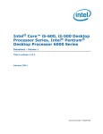
1
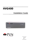
SVProxy3 User Guide October 2010 SerVision SVProxy3 User Guide Trademarks & Copyright Trademarks All trademarks mentioned in this manual are the sole property of their respective manufacturers. Copyright SerVision Ltd., Jerusalem, Israel www.servision.net • [email protected] © 2010 SerVision Ltd. All rights reserved. Notice Information in this document is subject to change without notice. SerVision Ltd. assumes no responsibility for any errors that may appear in this manual. Companies, names and data used in examples herein are fictitious unless otherwise noted. No part of this document may be copied or reproduced in any form, or by any means, electronic or mechanical, for any purpose, without the express written permission of SerVision Ltd. SerVision Ltd. makes no warranties with respect to this documentation and disclaims any implied warranties of merchantability or fitness for a particular purpose. sw v 0.0.20 doc v 2-2 1 SerVision SVProxy3 User Guide Table of Contents Introduction 3 Proxy Service 4 Video Distribution 4 DDNS 5 Product Versions 6 Hardware Version Software Version 6 6 Additional Equipment 7 This Guide 7 Installing the Hardware Unit 9 Package Contents 9 Diagrams of Connectors 9 Installing the Unit 10 Installing the Software on a Server 11 Configuring SVProxy3 12 Opening the Configuration Utility Opening the Configuration Utility via a VGA Monitor Opening the Configuration Utility via a Browser 12 12 12 Logging In 14 Overview of the Interface 15 Top-Level Menu Options Status Bar Using the Configuration Utility Video Distributor Settings Managing the List of Video Gateways Managing SVProxy3 Client User Accounts 16 16 17 17 18 21 SVDDNS Settings 25 System Settings 27 WebMax Settings Network Configuration Settings General Settings Port Configuration Backup and Restoration Resetting the Unit Activating the SVProxy3 Software Viewing Video from SVProxy3 28 33 35 36 39 44 46 48 Viewing Video in the MultiClient 49 Viewing Video in a PDA or Cellular Phone Client 51 Troubleshooting Network Connections Ping Testing Incoming Connections Using Ping Testing Outgoing Connections Using Ping Traceroute Testing Incoming Connections Using Traceroute Testing Outgoing Connections Using Traceroute 52 52 52 54 56 57 59 2 SerVision SVProxy3 User Guide Introduction SerVision security systems are compact video gateways that provide state-of-the-art security functionality, including live video transmission, video recording and playback, motion detection, sensor management, real-time event notification, and device activation. The systems can be accessed remotely via PC, PDA, or cellular phone using SerVision client applications. SVProxy3 is an application that was developed by SerVision to work in conjunction with its video gateways and client applications. When the application is installed on a server that is connected to the internet, it can facilitate and extend the video transmission capabilities of SerVision systems by providing the following services: • Proxy service: Enables video transmission over networks that do not allow client devices to connect to video gateways directly • Video distribution service: Enables larger numbers of client applications to receive video from a video gateway simultaneously • Dynamic DNS (DDNS) service: Facilitates client connections to video gateways that have dynamic public IP addresses SVProxy3 performs its video-distribution and proxy-service functions by acting as an intermediary between SerVision video gateways and SerVision client applications. When these services are used, all communication between video gateways and client applications, including the transmission of video, go through SVProxy3. Figure 1: SVProxy3 mediating between a video gateway and clients When SVProxy3 acts as a DDNS server, it keeps track of the current IP addresses of the video gateways it monitors and relays this information to the DNS servers on the internet. Before a client application connects to one of these video gateways, it finds out what the current IP address of the video gateway is from one of these DNS servers. In order to provide these services, SVProxy3 must be installed on a server that has a broadband connection to the internet. For the proxy and video-distribution services, the upload capacity of the line should be sufficient to enable SVProxy3 to upload video at one time to as many clients as required. In addition, the upload bandwidth of all the segments of the line connecting a client to SVProxy3 must be broad enough to support the transmission of the required video. That is, point-to-point, from SVProxy3 to each client, the upload capacity must be sufficient for the video that will be transmitted. Introduction 3 SerVision SVProxy3 User Guide Proxy Service The proxy service that is provided by SVProxy3 enables video transmission in situations in which direct connections between video gateways and clients cannot be established. This service is particularly useful in the following situations: • Cellular networks: When a video gateway connects to the internet via a cellular network, and the cellular carrier does not permit other external devices to initiate direct connections to the network • Firewalls: When a router or other firewall prevents clients from connecting to a video gateway When the proxy service is used, video gateways are configured to automatically connect to SVProxy3's proxy server when they start running. Similarly, client applications are configured to connect to these video gateways indirectly by connecting to the proxy server. Once these connections are established, SVProxy3 accepts requests from client applications and relays them to video gateways. The video gateways send their responses to SVProxy3, and it, in turn, passes the responses back to the client applications. If clients request video streams, SVProxy3 receives them from the video gateways frame-by-frame, and relays the frames to the client devices as it receives them. Figure 2: SVProxy linking a video gateway to clients Video Distribution SerVision video gateways are capable of uploading video to relatively large numbers of users simultaneously. However, in many cases the networks through which they upload the video place significant limitations on how much video can be uploaded at one time, because the upload bandwidth is quite narrow. As a result, a video gateway may only be able to upload one or two good-quality video streams at a time. SVProxy3's SVDistributor service circumvents this problem, making it possible for numerous users to receive highquality live video from a single SerVision video gateway simultaneously, even when the upload bandwidth available to the video gateway is not sufficient for multiple users. To accomplish this, SVDistributor functions as both a client vis-à-vis the video gateway and as a server vis-à-vis client devices. In its role as a client, it connects to the video gateway and retrieves a video stream from it. In its role as a server, it uploads the video it receives to other clients using its extensive upload bandwidth. Introduction 4 SerVision SVProxy3 User Guide Figure 3: SVDistributor relaying a video stream from a video gateway to multiple clients DDNS SVProxy3's Dynamic Domain Name Service, SVDDNS, helps client devices locate video gateways that have dynamic public IP addresses. Each video gateway that uses this service has a name by which it is identified. The video gateway automatically connects to SVProxy3's SVDDNS server at frequent intervals. When it does so, the SVDDNS server retrieves the video gateway's name and current IP address. It stores this information in its database and also relays it to the global DNS service – the interconnected system of DDNS and DNS servers on the internet. Client applications use the global DNS service to find out the current IP address of a video gateway before they connect to it. They provide the name of the video gateway, and the DNS service gives them the IP address. Once they have the current IP address of the video gateway, the clients can use it to connect to the video gateway directly, through the internet. Figure 4: SVDDNS relaying the IP address of a video gateway to the global DNS service for clients to retrieve Introduction 5 SerVision SVProxy3 User Guide Product Versions SVProxy3 can be supplied in one of two forms: • Hardware: The application is preinstalled on a server unit which is supplied to the customer. • Software: The application is provided as software for installation on a server unit that is provided by the customer. Hardware Version The hardware version consists of the SVProxy3 application preinstalled on a server unit that is powerful enough to support the product and enables it to communicate with large numbers of video gateways and client applications simultaneously. In order to use the server, the customer connects it to a LAN that has a broadband connection to the internet. Figure 5: SVProxy3 server unit Software Version Some customers prefer to install the SVProxy3 application on servers that they provide. In this case, SerVision provides the SVProxy3 software, and the customer installs it on the server. If you choose to provide your own server, the server must meet the minimum requirements specified below. It is recommended that you purchase a server that exactly matches the recommended system. If you do so, the application should run properly as soon as it is installed and configured. If you choose to use other hardware, you must consult with SerVision's R&D team before you purchase it in order to ensure that the hardware is compatible with the application. In some cases, the R&D team may have to implement some customizations in order to make the application compatible with your hardware. NOTE: The server can only be used for the SVProxy3 software. If it contains any other data, the data is erased during the software installation process. Minimum Requirements If you choose to provide your own server, it must meet the following minimum requirements: • CPU: Intel Core2DUO 2.0Ghz @ 800 Mhz FSB and above • RAM: 4GB DDR2 • HDD: 20 GB SATA or IDE HDD (recommended: 160GB) • CDROM: The server must have a CDROM. • Hardware: All hardware must be Linux-certified (2.6 kernel). Introduction 6 SerVision SVProxy3 User Guide Recommended System If you choose to provide your own server, it is recommended that the server match the following specifications: • Component • Specification Motherboard One of the following: • Make: GIGABYTE; Model: GA-G31M-ES2L (*rev. 1.x) See: http://www.gigabyte.com.tw/Products/Motherboard/Products_Overview.aspx? ProductID=2889 • Make: GIGABYTE; Model: GA-G31M-ES2L (rev. 2.x) See: http://www.gigabyte.com/products/product-page.aspx?pid=3134 Note: Rev. 2.3 versions of the GIGABYTE motherboards are not currently supported by the SVProxy3 application. CPU Make: Intel®; Model: Core™2 Duo Desktop Processor E7400 See: http://processorfinder.intel.com/details.aspx?sSpec=SLB9Y Memory 4 GB Note: The software can run with 2GB of memory, but the system may become unstable at high loads. 4 GB is the maximum capacity for this board. Note: Use memory sticks that are compatible with the motherboard. Video card The video card installed on the recommended motherboards is sufficient. CDROM The server must have a CDROM. Hard disk drive Type: SATA Minimum storage capacity: 20 GB (recommended: 160 GB) Installation: Must be installed in the SATA 0 slot Power supply Any model that is compatible with the recommended motherboard is acceptable. Additional Equipment In order to configure SVProxy3 the first time, you will need the following additional equipment: • VGA monitor • Keyboard • PS2 mouse This Guide This guide explains how to install and configure your SVProxy3 so that it can receive video from your video gateways and relay it to users who connect to it by means of SerVision client applications such as the MultiClient. The following topics are covered in this manual: • Installing a SerVision-supplied unit (page 9) • Installing the software on a server (page 11) • Configuring SVProxy3 (page 12) Introduction 7 SerVision SVProxy3 User Guide • Viewing video from SVProxy3 in the MultiClient and other client applications (page 48) • Troubleshooting network connection problems using Ping and Traceroute (page 52) Introduction 8 SerVision SVProxy3 User Guide Installing the Hardware Unit This section explains how to set up and start an SVProxy3 server unit that is supplied by SerVision. If you are installing the software on your own server, see Installing the Software on a Server, page 11. Package Contents When SVProxy3 is supplied preinstalled on a server unit, the SVProxy3 package includes the following items: • SVProxy3 unit • Ethernet (LAN) cable • Power supply cable • Keys for opening the cover of the front panel Diagrams of Connectors The figures below indicate where the required connectors and controls are located on the unit. NOTE: The layout of the connectors may differ slightly from the arrangement in the illustrations. Power connector Ethernet connector Power switch Keyboard connector Connector for VGA monitor Mouse connector Figure 6: SVProxy3 rear panel Installing the Hardware Unit 9 SerVision SVProxy3 User Guide Reset switch Figure 7: SVProxy3 front panel Installing the Unit The SVProxy3 server is installed by connecting it to the LAN and turning it on, as follows: To install the SVProxy3 unit: 1. Connect the Ethernet connector on the rear panel of the SVProxy3 unit to a LAN connection point (a hub, wall socket, or any other connection point) using the Ethernet cable. 2. Connect the power connector on the rear panel of the SVProxy3 unit to a standard wall socket using the power-supply cable. 3. On the rear panel of the unit, turn on the power switch (the I is down and the O is up). The unit starts up. Installing the Hardware Unit 10 SerVision SVProxy3 User Guide Installing the Software on a Server If you are providing your own server for the SVProxy3 software, you must install the software on the server. An installation disk or an installation package (ISO image) is supplied by SerVision for this purpose. After you install the software, you can configure the application, but you cannot use any of its features until you get a license number from SerVision and activate the application (see Activating the SVProxy3 Software, page 46). NOTE: The server can only be used for SVProxy3. If it contains any other data, the data is erased during the software installation process. To install the SVProxy3 software on a server: 1. If you received an installation package, burn it onto a CD to create an installation disk. 2. Insert the installation disk into the server's CD or DVD drive, and then restart the server. 3. As soon as the server restarts, open the BIOS Setup and make sure the server is configured to boot from the CD drive first (i.e., the first boot device is the CD drive). 4. Close the BIOS Setup. The server boots from the installation CD and the installation process starts. You are prompted to confirm that you want to install the application. 5. Select Yes. The software is installed. When the process is completed, the installation CD is ejected and the server shuts down. When you restart the server, the application starts automatically. Installing the Software on a Server 11 SerVision SVProxy3 User Guide Configuring SVProxy3 To get SVProxy3 up and running, you must configure it and connect it to a LAN with internet access. Be sure the LAN has sufficient upload bandwidth to supply video to all of the intended clients. In addition, ensure that the router (network gateway) through which the unit connects to the internet has a static public IP address. SVProxy3 is configured using a browser-based configuration utility called WebMax. Initial configuration is performed using a VGA monitor, keyboard, and mouse connected directly to the server unit. No internet connection is required to configure the unit. After the initial configuration, you can access the configuration utility through any PC on the LAN, or remotely via the internet. The utility is compatible with most browsers, including Internet Explorer and Firefox. This chapter explains how to open the configuration utility and use it to configure SVProxy3. Opening the Configuration Utility You can open the configuration utility in one of two ways: • By connecting a VGA monitor to the TV-Out connector on the server • By connecting to the sever from a computer, using a browser The first time you open the configuration utility, you should use the first method. Once you have configured the unit's network settings, you can use either method. Opening the Configuration Utility via a VGA Monitor In order to open SVProxy3's configuration utility using a VGA monitor, you must connect the following to the unit: • VGA monitor • Keyboard • PS2 Mouse When the monitor is connected to the unit, it automatically displays the configuration utility. See Logging In, page 14. Opening the Configuration Utility via a Browser Once you have set the network settings of the SVProxy3 unit, you can connect to it from a computer on the local network or the internet. This can be done in one of two ways: • Through the MultiClient: Connect to SVProxy3 through the MultiClient and use it to access the configuration utility, as described below. • Manually through a browser: Enter SVProxy3's address and Webmax port in the Address field of a browser window, as described under Opening the Configuration Utility Manually in a Browser, page 13. Opening the Configuration Utility Using the MultiClient The MultiClient is SerVision's client application for PCs. When you are connected to SVProxy3 through the MultiClient, you can use the MultiClient to open the configuration utility in your browser. NOTE: If the MultiClient is not installed on the PC, install it from the CD that came with the unit or download it at http://www.servision.net. For information about installing and using the MultiClient, please refer to the MultiClient Quick-Start Guide or the MultiClient User Guide. Configuring SVProxy3 12 SerVision SVProxy3 User Guide To open the configuration utility through the MultiClient: 1. Connect to SVProxy3 through the MultiClient. (See Viewing Video from SVProxy3, page 48.) 2. In the Connection Panel (the left panel) of the MultiClient, select the SVProxy3 unit. 3. At the bottom of the Connection Panel, click the Config button. A new browser window opens, and automatically connects to SVProxy3's Webmax Login screen (see Logging In, page 14). Note: If you are connecting remotely, and you cannot connect through port 10000, the Login screen will not appear at this point, and the browser will display an error message instead. Change the port number in the Address field of the browser from 10000 to the additional Webmax port (see Port Configuration, page 36), and press Enter to reload the page. The Login screen should then appear. For additional information, see Opening the Configuration Utility Manually in a Browser, below. Note: If more than one SerVision server (video gateway or SVProxy3) is connected to the internet via the same router, each of them must use a different port. When you click Config in the MultiClient, the browser automatically connects to port 10000. As a result, the MultiClient may initially connect you to the wrong video gateway unit. In this case, you should manually correct the port number in the Address field of the browser, as explained in the previous note. Opening the Configuration Utility Manually in a Browser The configuration utility can be opened manually in a browser using the IP address and port of the unit. This is particularly useful in situations in which you cannot open the configuration utility through the MultiClient. This is most likely to occur when you are opening the configuration utility remotely and either do not have access to the MultiClient or cannot connect to the unit remotely through port 10000. To open the configuration utility manually, you must know the network address (IP or hostname) of the SVProxy3 unit and the port that is used to access the configuration utility. The required network address and port depend on whether you are accessing the configuration utility through a local connection (through the same LAN or through a LAN cross cable) or a remote connection (through the internet): • Local connection: The network address is the private IP address of the SVProxy3 unit on the local network. This can either be its dynamic IP, or, if it has one, its static IP. The port can be either port 10000 or the additional Webmax port (see Port Configuration, page 36). • Remote connection: The network address is the public IP or hostname of the router through which the SVProxy3 unit connects to the internet. The port is the port set in the router for port forwarding to the configuration utility. To open the configuration utility manually: 1. Open a web browser. 2. In the Address field of the browser, enter the IP address and configuration port number of the SVProxy3 unit, in the following format: http://IP:port For example, if SVProxy3’s IP address is 192.168.1.210 and you are connecting on port 10000, enter http://192.168.1.210:10000, as in figure 8: Figure 8: Address for configuring a unit with a static IP The configuration utility Login screen opens. Configuring SVProxy3 13 SerVision SVProxy3 User Guide 3. Log into the configuration utility as usual (see below). Logging In Regardless of how you open the configuration utility, when you first open it, the Login screen is displayed: Figure 9: Login screen To log into the configuration utility: 1. In the Login screen, fill in the User Name and Password fields. Note: By default, the user name is svuser and the password is servconf. Use these values the first time you log into the configuration utility. Once you have logged in, you should change these values (see Modifying a WebMax User Account, page 30). 2. Click Login. The configuration utility opens, and the System Summary screen is displayed: Configuring SVProxy3 14 SerVision SVProxy3 User Guide Figure 10: System Summary screen Overview of the Interface The configuration utility consists of screens that are displayed on the right side of the window, a main menu in a sidebar on the left side of the window, and a status bar across the top. The main menu is used for opening the configuration utility screens, which are displayed on the right side of the window. The main menu is hierarchic – some of the options have sub-menus that can be accessed when they are selected. Main menu Screen Status bar Selected top-level screen Lower-level option Figure 11: Elements of the interface Configuring SVProxy3 15 SerVision SVProxy3 User Guide Top-Level Menu Options The following top-level menu options are available: • Option • Description Summary Displays a summary of the system's settings and status Video Distributor • Management of the list of video gateways monitored by the system (see page 21) • Management of client access to the system (see page 18) SVDDNS Activation and configuration of the SerVision DDNS service (see page 25) System • Configuration of general system settings, including network settings, security, and authentication (see page 27) • Rebooting or shutting down the unit (see page 44) • Backing up the current settings; restoring settings from a backup (see page 39) • License activation (see page 46) Network troubleshooting tools: Ping and Traceroute (see page 52) Tools Status Bar A status bar at the top of the screen contains the following elements: Name Version User Status Help Logout Figure 12: Status bar elements • Name: Name of the system (see page 35) Configuring SVProxy3 16 SerVision SVProxy3 User Guide • Version: Firmware version • User: The username of the user currently logged in (see page 28) • Status: Whether the license is activated or not (see page 46) • Logout: Click to log out of the configuration utility and display the Login screen again • Help: Click to open the SerVision website in a browser window. The website includes information about configuring and working with your SVProxy3 system, including the most up-to-date version of this manual (under Support->Documentation->Manuals and Product Overviews) Using the Configuration Utility The configuration process typically proceeds as follows: To configure SVProxy3: 1. In the main menu, click one of the options to open a top-level screen. 2. If you need to open a lower-level screen, in the sub-menu of the selected option, click the name of the screen. 3. Modify the settings in the screen as necessary, and then click Update to store them on the unit. The changes are saved in a temporary cache on the unit. A Save button appears in the lower right corner of the screen. 4. Click the Save button to save the changes on the unit. A backup copy of the previous settings is automatically saved on the unit, and can be restored later if necessary (see Backup and Restoration, page 39). 5. To modify additional settings, navigate to the relevant screen and make the changes as necessary. Click Update in each screen when you are finished modifying its settings. Then click Save to save the changes you have made. (The Save button remains visible until you click it. When you click it, all unsaved changes are saved on the unit – even changes that were made in other screens, as long as you clicked Update in them.) 6. If two-tiered authorization is activated, have another user log in and confirm all of the changes (see Activating Two-Tiered Authorization, page 32). 7. In the main menu, under System, click Restart Panel. The Restart Panel screen opens. 8. If a Save button appears in the lower right of the screen, click it to save all remaining unsaved changes. 9. Click System Reboot. The system restarts and the changes to the configuration are implemented. You are automatically logged out of the system. When the reboot is complete, the Login screen appears. NOTE: Most changes to the settings in the configuration screens only take effect on the server after they are saved and the server is restarted. For additional information, see Resetting the Unit, page 44. NOTE: Logging in and out of the configuration utility does not cause saved settings to be implemented. Video Distributor Settings Because SVProxy3 connects to video gateways as a client application, it must have client-access information, such as the IP address and client port, for each video gateway from which it can retrieve video. For this purpose, its configuration includes a list of video gateways it monitors – the video gateways to which it can connect, and connection information for each one. When other SerVision clients connect to SVProxy3 in order to retrieve video from one of the video gateways it monitors, they connect to SVProxy3 as SVProxy3's clients. In order to ensure that only authorized clients can use SVProxy3 to retrieve video from video gateways, authentication is required from clients that connect to SVProxy3. Configuring SVProxy3 17 SerVision SVProxy3 User Guide Managing the List of Video Gateways A list of video gateways from which SVProxy3 can retrieve video for distribution to users is defined in the configuration utility. SVProxy3 can only connect to video gateways that appear in the list. It can connect to the video gateways directly using their public IP address or by proxy using a SerVision SVProxy proxy server (either the built-in proxy server or an external SVProxy server). Adding a Video Gateway to the List If you want SVProxy3 to monitor a video gateway, you must add it to the list of video gateways in SVProxy3. To add video gateways to the list: 1. In the main menu, under Video Distributor, click Gateway Management. The Gateway Management screen opens. Figure 13: Gateway Management screen 2. Click Add New Gateway. The Create New Gateway screen opens. Configuring SVProxy3 18 SerVision SVProxy3 User Guide Figure 14: Create New Gateway screen 3. Fill in the fields as follows: • Field • Description Description Enter a description for the video gateway. This description identifies the video gateway in client applications. Gateway Model Select the model of the video gateway. Connection Type Select one of the following: Proxy Host/IP • Direct: SVProxy3 will connect to the video gateway directly. • Local Proxy: SVProxy3 will connect to the video gateway using the built-in proxy server. • Remote Proxy: SVProxy3 will connect to the video gateway using an external SerVision proxy server. The public IP address or hostname of the proxy server Note: This field only appears if the Remote Proxy connection type is selected. Proxy Port The port number used by the proxy server Note: This field only appears if the Remote Proxy connection type is selected. Gateway Host/IP • Direct connection: The IP address or hostname of the video gateway • Proxy connection: The name of the video gateway as it appears in its configuration Gateway Port • The video gateway's client-access port Username The username for client access to the video gateway Note: If “anonymous authentication” is selected in the video gateway configuration, this value is anonymous. Configuring SVProxy3 19 SerVision SVProxy3 User Guide • Field • Description Password The password for client access to the video gateway Note: If “anonymous authentication” is selected in the video gateway configuration, this value is guest. 4. Under User Permission to Access Gateway, select the users that have permissions to retrieve video from the video gateway. Note: These users are defined in the User Management screen (see Managing SVProxy3 Client User Accounts, page 21). 5. Click Update. The video gateway is added to the list of video gateways, and the list is displayed. A Save button appears at the lower right of the screen. Video gateway added to list Figure 15: Video gateway added to list 6. Click Save. The changes are saved on the unit. The changes are implemented after you restart the unit (see Resetting the Unit, page 44). Modifying the Settings of a Video Gateway You can modify the settings of a video gateway in SVProxy3's list as necessary. To modify the settings of a video gateway: 1. In the Gateway Management screen, click the line in which the video gateway is listed. The Edit Video Gateway screen opens. Configuring SVProxy3 20 SerVision SVProxy3 User Guide Figure 16: Edit Video Gateway screen 2. Modify the fields as required. 3. Click Update. The updated list of video gateways is displayed. A Save button appears at the lower right of the screen. 4. Click Save. The changes are saved on the unit. The changes are implemented after you restart the unit (see Resetting the Unit, page 44). Deleting a Video Gateway from the List If you no longer want SVProxy3 to monitor a video gateway, you can delete it from the list. To delete a video gateway from the list: 1. In Gateway Management screen, click the line in which the video gateway is listed. The Edit Video Gateway screen opens. 2. Click Delete. You are prompted to confirm that you want to delete the video gateway. 3. Click Yes. The updated list of video gateways is displayed. A Save button appears at the lower right of the screen. 4. Click Save. The changes are saved on the unit. The changes are implemented after you restart the unit (see Resetting the Unit, page 44). Managing SVProxy3 Client User Accounts You can define one or more client user accounts for SVProxy3. Each account can be linked to specific video gateways. Thus, user1 may be able to access video from video gateway 1, user2 from video gateway 2, and user3 from all video gateways monitored by SVProxy3. SVProxy3 will only transmit video from a video gateway to a client if the client's user account that has permissions to access the video gateway. Multiple client applications can connect to SVProxy3 using the same client user account simultaneously. Configuring SVProxy3 21 SerVision SVProxy3 User Guide NOTE: Video gateways can be linked to user accounts in either the User Management screen, as explained below, or the Gateway Management screen (see Adding a Video Gateway to the List, page 18). NOTE: Client user accounts enable client applications to receive video and other data from video gateways. They do not provide access to the configuration utility. User accounts for the configuration utility are managed under System, in the WebMax Users screen; see WebMax Settings, page 28. Adding a Client User Account You can add a client user account to SVProxy3 as necessary. To add a client user account to SVProxy3: 1. In the main menu, under Video Distributor, click User Management. The User Management screen opens. Figure 17: User Management screen 2. Click Add New User. The Create New User screen opens. Configuring SVProxy3 22 SerVision SVProxy3 User Guide Figure 18: Create New User screen 3. Fill in the fields as follows: • Field • Description User Name Enter a name for the user account. User Type Select one of the following: • User: This type of user only has permissions to access specified video gateways • Superuser: This type of user has permissions to access any video gateway monitored by SVProxy3. Password The password for the user account Confirm Password Type the password again to ensure you typed it correctly. 4. Under Permission to Access Gateways, select the video gateways the user has permissions to access. Note: These permissions can also be set in the Gateway Management screen (see Managing the List of Video Gateways, page 18). Note: If the User Type is Superuser, you can skip this step. The user will automatically have access to all of the video gateways. 5. Click Update. The user account is added to the list of users, and the list is displayed. A Save button appears at the lower right of the screen. Configuring SVProxy3 23 SerVision SVProxy3 User Guide User account added to list Figure 19: Client user account added to list 6. Click Save. The changes are saved on the unit. The changes are implemented after you restart the unit (see Resetting the Unit, page 44). Modifying a Client User Account You can modify the settings of a client user account as necessary. To modify the settings of a client user account: 1. In the User Management screen, click the line in which the account is listed. The Edit User screen opens. Figure 20: Edit User screen 2. Modify the User Name, User Type, and Permissions to Access Gateways fields as required. Configuring SVProxy3 24 SerVision SVProxy3 User Guide 3. If you want to change the password, click Change/Create Password. The Password and Confirm Password fields are added to the screen. Type the new password in both fields. Figure 21: Password and Confirm Password fields added to Edit User screen 4. Click Update. The updated list of client user accounts is displayed. A Save button appears at the lower right of the screen. 5. Click Save. The changes are saved on the unit. The changes are implemented after you restart the unit (see Resetting the Unit, page 44). Deleting a Client User Account You can delete client user accounts as necessary. To delete a client user account: 1. In the User Management screen, click the line in which the account is listed. The Edit User screen opens. 2. Click Delete. You are prompted to confirm that you want to delete the user account. 3. Click Yes. The updated list of user accounts is displayed. A Save button appears at the lower right of the screen. 4. Click Save. The changes are saved on the unit. The changes are implemented after you restart the unit (see Resetting the Unit, page 44). SVDDNS Settings SVDDNS is a DDNS (Dynamic Domain Name Service) server that facilitates client connections to video gateways that have dynamic IP addresses. In order to use the SVDDNS service, you must have an ICANN-registered domain name for the SVDDNS server. In addition, the SVProxy3 server must have a static public IP address. NOTE: The built-in SVDDNS service can also be used for video gateways that do not use SVProxy3's SVProxy or SVDistributor services. Once you have set up the SVDDNS service, you can configure your video gateways and client applications to use it. For information about configuring the DDNS settings of the video gateway, please refer to the unit's configuration guide. For client applications, all you have to do is use the DDNS name of the video gateway (its hostname and domain name; see below) rather than its IP address to connect to it. SerVision clients automatically check with DNS services to find out the current IP address of the video gateway before connecting to it. To set up the SVDDNS service: 1. In the main menu, click SVDDNS. The SVDDNS screen opens. Configuring SVProxy3 25 SerVision SVProxy3 User Guide Figure 22: SVDDNS screen 2. Select Enable SVDDNS. The fields required to configure the DDNS service are added to the screen. Figure 23: SVDDNS settings 3. Fill in the fields as follows: Configuring SVProxy3 26 SerVision SVProxy3 User Guide • Field • Description Registration Port The port to which video gateways should connect in order to register their current IP addresses with the DDNS server (default: 8888) Get IP Port The port to which video gateways should connect in order to request that the DDNS server check what their current external IP address is. This should be set to 8787. If this port is not available, please contact SerVision technical support. Domain The domain name of the DDNS server. For example, if you registered the domain myddns.com to use for the server, you would type myddns.com in this field. Note: Clients connect to video gateways that use this DDNS server using a hostname followed by this domain name. For example, mygateway.myddns.com. (By default, the hostname is the name of the video gateway, but it can be modified in the video gateway's DDNS configuration. For additional information, please refer to the video gateway's configuration guide.) TTL The Time to Live of each video gateway's IP address (default: 5 seconds) External Static IP The static external IP address of the DDNS server 4. Click Update. 5. Click Save. The changes are saved on the unit. The changes are implemented after you restart the unit (see Resetting the Unit, page 44). System Settings A variety of settings, including network settings and WebMax user account settings, are configured under the System option. In addition, backup and restore, system shutdown and reboot, and license activation can be accessed from the System sub-menu. The top-level System screen summarizes the current system settings. Figure 24: System screen The following lower-level screens are available: Configuring SVProxy3 27 SerVision SVProxy3 User Guide • WebMax: Managing user accounts for access to the configuration utility; activating two-tiered authorization (see page 28) • Network Settings: Configuring local network settings (see page 33) • General Settings: Specifying a name for the system and activating SSH access (see page 35) • Port Configuration: Specifying the port numbers for client-access, the proxy server, and Webmax (see page 36) • Backup and Restoration: Making a backup copy of the current configuration settings; restoring the settings from a previous backup (see page 39) WebMax Settings The WebMax screens control user access to the configuration utility. Two features are configured in these screens: • Management of WebMax user accounts • Activation of two-tiered authorization: When this feature is activated, configuration changes must be confirmed by a second user before they are implemented NOTE: User accounts for client access are managed under Video Distributor, in the User Management screen; see Managing SVProxy3 Client User Accounts, page 21. Managing WebMax User Accounts WebMax user accounts enable users to access the configuration utility and modify the settings in it. All WebMax users have the same permissions. By default, one WebMax user is defined, with username svuser and password servconf. It is recommended that you change these values. In addition, you can add additional user accounts. Adding a WebMax User Account You can add as many WebMax user accounts as you require. If you want to use two-tiered authorization (see Activating Two-Tiered Authorization, page 32), at least two accounts must be defined. To add a WebMax user account: 1. In the main menu, under System, click WebMax and then click WebMax Users. The WebMax Users screen opens. Configuring SVProxy3 28 SerVision SVProxy3 User Guide Figure 25: WebMax Users screen 2. Click Create New WebMax User. The Create New User screen opens. Figure 26: Create New User screen 3. Fill in the fields as follows: Configuring SVProxy3 29 SerVision SVProxy3 User Guide • Field • Description User Name Enter a name for the user account. Password Enter a password for the user account Confirm Password Type the password again to ensure you typed it correctly. 4. Click Update. The user account is added to the list of users, and the list is displayed. A Save button appears at the lower right of the screen. User account added to list Figure 27: WebMax user account added to list 5. Click Save. The changes are saved and implemented. (It is not necessary to restart the unit.) Modifying a WebMax User Account You can modify the settings of a WebMax user account as necessary. To modify the settings of a WebMax user account: 1. In the WebMax Users screen, click the line in which the account is listed. The Edit WebMax User screen opens. Configuring SVProxy3 30 SerVision SVProxy3 User Guide Figure 28: Edit WebMax User screen 2. Modify the User Name as required. 3. If you want to change the password, click Change/Create Password. The Password and Confirm Password fields are added to the screen. Type the new password in both fields. Figure 29: Password and Confirm Password fields added to Edit WebMax User screen 4. Click Update. The updated list of client user accounts is displayed. A Save button appears at the lower right of the screen. 5. Click Save. The changes are saved and implemented. (It is not necessary to restart the unit.) Deleting a WebMax User Account You can delete WebMax user accounts as necessary. At least one user account must be defined at all times. To delete a WebMax user account: 1. In the WebMax Users screen, click the line in which the account is listed. The Edit WebMax User screen opens. 2. Click Delete. You are prompted to confirm that you want to delete the account. Configuring SVProxy3 31 SerVision SVProxy3 User Guide 3. Click Yes. The updated list of WebMax users is displayed. A Save button appears at the lower right of the screen. 4. Click Save. The changes are saved and implemented. (It is not necessary to restart the unit.) Activating Two-Tiered Authorization When two-tiered authorization is activated, changes to configuration settings are only implemented if two users confirm them. In this case, if you modify a setting, when you are logged into the configuration utility, appears beside the new value until another WebMax user confirms the change. If another user modifies a setting, when you are logged in, appears beside the new value they set until it is confirmed. User account added by current user and not yet confirmed Figure 30: Unconfirmed change made by current user Configuring SVProxy3 32 SerVision SVProxy3 User Guide User account added by another user and not yet confirmed Figure 31: Unconfirmed change made by another user To confirm a change made by another user: 1. Click the beside the field that was changed. The of the screen. disappears and a Save button appears on the lower right 2. Click Save. The change is saved on the unit. Restart the unit in order to implement it (see Resetting the Unit, page 44; changes to WebMax user account settings do not require a restart). To cancel a change made by any user (yourself or another user): 1. Click the beside the field that was changed. The change is undone in the WebMax display, and the disappears. A Save button appears on the lower right of the screen. or 2. Click Save. The change is canceled. Network Configuration Settings The local IP address of the SVProxy3 unit is configured in the Network Configuration screen. By default, SVProxy3 is set to acquire a dynamic local IP address from a DHCP server on the LAN. If you do not need to assign a static local IP to the unit, you can leave this setting as it is. If you need to assign a static local IP address to the unit – for example, if you are using the SVDDNS server, or your LAN does not have a DHCP server – you can specify the IP and other network settings manually. To adjust the network settings: 1. In the main menu, under System, click Network Configuration. The Network Configuration screen opens: Configuring SVProxy3 33 SerVision SVProxy3 User Guide Figure 32: Network Configuration screen 2. If you want to assign a static local IP address to the unit, select the Static IP checkbox. The fields required to configure the static IP are added to the screen. Figure 33: Static IP settings Fill in the fields as follows: • Field • Description IP The static IP address of the unit on the LAN. The address should conform to the standards used in your network, and should be unique in the network. Netmask The LAN subnet mask. The subnet mask should conform to the one your network uses. Broadcast The broadcast IP of your network. The broadcast IP identifies the range of IPs that are Configuring SVProxy3 34 SerVision SVProxy3 User Guide • Field • Description recognized by the network gateway as being included in its local network. Default Gateway The internal IP address of the LAN’s router (network gateway) If you do not know this value, contact your ISP or your network administrator. Note: If this field is not filled in correctly, you will not be able to access the unit from outside the network, but you will be able to connect to the unit by running the MultiClient on a computer on the same network as the unit. DNS 1 The IP address of the primary DNS server used by the LAN. A DNS server enables you to enter names instead of IP addresses for video gateways and for the proxy and DDNS servers. The DNS server may be operated by your internet provider (home installation) or on your network (some office installations). If you do not know the IP address of the DNS server, contact your ISP or your network administrator. DNS 2 The IP address of an additional DNS server that is used by the LAN (optional) 3. Click Update. 4. Click Save. The changes are saved on the unit. The changes are implemented after you restart the unit (see Resetting the Unit, page 44). General Settings The name of the SVProxy3 system is set under General Settings. In addition, if necessary, you can activate SSH access under General Settings. Specifying a Name for the SVProxy3 Unit You can specify a name for the SVProxy3 unit. This name identifies the unit in client applications such as the MultiClient. To specify a name for the unit: 1. In the main menu, under System, click General Settings. The General Settings screen opens. Configuring SVProxy3 35 SerVision SVProxy3 User Guide Figure 34: General Settings screen 2. Under System Name, modify the current name as required. Do not include blank spaces or special characters in the name. 3. Click Update. 4. Click Save. The new name is saved on the unit. The change is implemented after you restart the unit (see Resetting the Unit, page 44). Activating SSH Access In general, it is not recommended to activate SSH for security purposes. In some cases, SerVision technical support staff may ask you to temporarily activate SSH. To activate SSH access: 1. In the main menu, under System, click General Settings. The General Settings screen opens. 2. Select Enable SSH. 3. Click Update. 4. Click Save. 5. Restart the unit. The change is implemented (see Resetting the Unit, page 44). Port Configuration SVProxy3 uses a number of ports for different purposes. The ports used for client access, for proxy connections, and for access to the configuration utility can all be configured under Port Configuration. NOTE: The ports used by the SVDDNS service are configured under SVDDNS (see SVDDNS Settings, page 25). Configuring SVProxy3 36 SerVision NOTE: SVProxy3 User Guide The ports configured here are the ports on the local network. To connect to one of these ports remotely, you must set up port forwarding on your router, and use the port number that is set in the port forwarding. Video Distributor Port The Video Distributor port is the port that client's use to connect to SVDistributor in order to retrieve a video stream from a video gateway. By default, the port is 9988. You can change this port number as necessary. Proxy Port When SVProxy3 is running, the built-in proxy server is automatically activated. To use it to establish connections between clients and video gateways, you must configure the video gateways to connect to it. The proxy server does not require any configuration. If necessary, you can change its access port. AES Ports SVProxy3 can relay video in unencrypted or encrypted form. If you want a client application to receive encrypted video from a video gateway, you must configure the client to do so. To do this, in the client application, in the video gateway's properties, under Encryption, select AES. Then, for the video gateway's port, use the VD AES port that is defined in SVProxy3's Port Configuration screen. If the video gateway uses a proxy connection, use the Proxy AES port. WebMax Port Port 10000 is hard-coded in SVProxy3 for connections to the configuration utility. If you cannot set up port forwarding for this port in your network, and you want to be able to connect to the configuration utility remotely, you can add an additional WebMax port. You can use any available port number you wish, except for those that are already used by SVProxy3 for other purposes. (See below for a list of reserved port numbers.) Configuring the Ports If the default port numbers for client access, proxy connections, and/or access to WebMax are not suitable in your network, you can modify the ports as necessary. The following port numbers are reserved and should not be used: 22, 23, 8810, 10000 In addition, be sure not to use any of the port numbers that are being used by the SVDDNS service (see SVDDNS Settings, page 25), or that are already in use for one of the other system ports. To modify the port settings: 1. In the main menu, under System, click Port Configuration. The Port Configuration screen opens: Configuring SVProxy3 37 SerVision SVProxy3 User Guide Figure 35: Port Configuration screen 2. Modify the following port numbers as required: • Field • Description VD Port Client access port for unencrypted video VD AES Port Client access port for encrypted video Proxy Port Client access port for unencrypted video from video gateways that use the built-in proxy service Proxy AES Port Client access port for encrypted video from video gateways that use the built-in proxy service 3. If you want to define an additional port for access to the configuration utility, select Additional WebMax port. The WebMax Port field is added to the screen. (If this field is not visible, use the scrollbar to the right of the WebMax Port area to scroll down until it appears.) By default, the port 10001 is defined in the field. Modify the port number as necessary. Configuring SVProxy3 38 SerVision SVProxy3 User Guide Figure 36: Port Configuration screen with WebMax Port field 4. Click Update. 5. Click Save. The changes are saved on the unit. The changes are implemented after you restart the unit (see Resetting the Unit, page 44). Backup and Restoration Whenever you save settings using the configuration utility, a backup copy of the previous set of settings is automatically saved by the system. You can also manually save a backup copy of SVProxy3's current configuration settings for later restoration. This can be useful if you want to use alternative sets of settings or copy the settings to another SVProxy3 unit. Automatic backups are saved as restoration points on SVProxy3. Manual backups can be saved either as restoration points on SVProxy3 or in backup files on the PC from which you are connecting to the configuration utility. If you want to use the Backup feature to copy the configuration settings from one SVProxy3 to another, you should save the backup of the source SVProxy3 as a file and then use the restoration option on the target SVProxy3 to copy the settings from the file. Backing Up the Current Configuration Settings You can manually back up the current system settings in one of two ways: as a restoration point that is stored on SVProxy3 or in a file that is saved on your PC. You can store up to 25 restoration points on SVProxy3. If you create a 26th restoration point, the oldest restoration point is deleted and the new one is saved. To back up the current settings: 1. In the main menu, under System, select Backup and Restoration. The Backup and Restoration screen opens. Configuring SVProxy3 39 SerVision SVProxy3 User Guide Figure 37: Backup and Restoration screen 2. Select Backup. The backup options appear. Figure 38: Backup options 3. Select the required option. An Execute button appears on the lower right of the screen. 4. Click Execute. • If you selected Create Local Restoration Point: The restoration point is saved on SVProxy3, and a confirmation message is displayed. • If you selected Download Backup of Configuration to PC: 1. You may be prompted to choose whether you want to open or save the file. If so, select Save. 2. A Windows file-save dialog box opens. Navigate to the folder in which you want to save the configuration file. If you wish, under File name, change the file name. Then click Save. The backup file is saved. Configuring SVProxy3 40 SerVision SVProxy3 User Guide Restoring Settings from a Backup You can copy saved configuration settings from a restoration point on SVProxy3 or a backup file as required. If you copy the settings from a backup file, you can choose to exclude the network and WebMax user settings. Whenever you restore settings from a backup, the system automatically creates a new restoration point and stores it on the unit. Thus, if you want to revert to the settings that were in place before the restoration, you can reinstate them by restoring the new restoration point. Restoring Settings from a Restoration Point You can copy saved configuration settings from a restoration point saved on SVProxy3 as required. To restore configuration settings from a restoration point: 1. In the main menu, under System, select Backup and Restoration. The Backup and Restoration screen opens. 2. Select Restore. The restoration options appear. Figure 39: Restoration options 3. Select Restore From Local Restoration Point. A list of available restoration points is displayed. Configuring SVProxy3 41 SerVision SVProxy3 User Guide Figure 40: List of available restoration points 4. Select the required restoration point. An Execute button appears on the lower right of the screen. 5. Click Execute. The settings are copied from the restoration point to the SVProxy3 unit, and a confirmation message appears. In addition, a new restoration point, containing the settings that were in force before you clicked Execute, is created. The system automatically reboots. After it reboots, the settings that were copied from the restoration point are implemented. Figure 41: Confirmation message after restoration from a restoration point Restoring Settings from a Backup File You can restore settings from a backup file on your PC as required. When you do, you can choose whether to copy all of the settings or to exclude some or all of the following types of settings: • Network settings • Webmax user account settings • The Webmax port setting These options make it possible to copy some of the settings that were saved from a different SVProxy3 unit without changing the settings that control access to the unit. To restore configuration settings from a backup file: 1. In the main menu, under System, select Backup and Restoration. The Backup and Restoration screen opens. 2. Select Restore. The restoration options appear. Configuring SVProxy3 42 SerVision SVProxy3 User Guide Figure 42: Restoration options 3. Select Restore From Saved Backup File (Upload from PC). The fields required to select the file and the restoration options are added to the screen. Figure 43: Restoration from file – added fields 4. Click Browse. A Windows file selector dialog box opens. 5. Navigate to the backup file, select it, and then click Open. The dialog box closes, and the file name and path appear in the text field. Configuring SVProxy3 43 SerVision SVProxy3 User Guide 6. If you want to include network and/or Webmax user settings in the restoration process, select the settings you want to include. If you do not select any of these options, all of the settings in the backup file except for these settings will be copied to the SVProxy3 configuration. 7. Click Update. The settings are copied from the backup file to the SVProxy3 unit, and a confirmation message appears. In addition, a new restoration point, containing the settings that were in force before you clicked Execute, is created. The system automatically reboots. After it reboots, the settings that were copied from the backup file are implemented. Figure 44: Confirmation message after restoration from a backup file Resetting the Unit If the SVProxy3 application stops responding, you can reset the unit. Resetting the unit shuts the unit down and restarts it. The following instructions explain how to reset a SerVision hardware unit. If your SVProxy3 is running on a different type of server, consult the server's documentation for information about resetting the unit. To reset a SerVision SVProxy3 server: 1. Using one of the supplied keys, open the front panel of the unit. 2. Press the Reset button (see Figure 7, page 10). The unit resets. Implementing Changes Implementing configuration changes is a three-stage process: 1. Updating: As you make changes in each WebMax screen, you click the Update button to validate them. Clicking Update saves your changes in a temporary cache on the client device, and displays them in the configuration utility. 2. Saving: When you click Update, a Save button appears in the lower right corner of the screen. When you click the Save button, the changes you have made are saved in SVProxy3. The Save button remains visible until you click it. If you made a number of updates before you clicked the Save button, all of the updates are saved when you click it. 3. Implementing: Changes are not implemented until you reboot the system, as described below. (There is one exception to this: Changes to WebMax user settings are implemented when you click Save; no reboot is required.) Rebooting the Unit You must reboot the unit in order to implement saved changes (except for changes to the Webmax user settings). To reboot the unit: 1. In the main menu, under System, select Restart Panel. The Restart Panel screen opens: Configuring SVProxy3 44 SerVision SVProxy3 User Guide Figure 45: Restart Panel screen 2. If you made configuration changes but did not yet click Save to save them in SVProxy3, a Save button appears in the lower right of the screen. Click Save to save the changes. 3. Click System Reboot. The system restarts and all changes are implemented. You are automatically logged out. When the system has rebooted, the Login screen appears. Login again if you want to view or modify the current configuration settings. Shutting Down the Unit This procedure is generally performed when you want to turn the unit off for a period of time. For example, you would do this if you want to move the unit to a different location. During this procedure, you first shut down the SVProxy3 application and then turn off the power to the unit. It is not recommended to turn off the unit's power unless you shut down the application first. NOTE: If you use the configuration utility to shut down the SVProxy3 application, as described below, when you are logged into the configuration utility remotely and do not have physical access to the SVProxy3 unit, you will not be able to turn the SVProxy3 back on or access it again until you can manually press the unit's power switch. NOTE: When you want to turn the unit on again, use the power switch on the unit to turn it back on. The application will automatically restart. To shut down the unit: 1. In the main menu, under System, select Restart Panel. The Restart Panel screen opens: Configuring SVProxy3 45 SerVision SVProxy3 User Guide Figure 46: Restart Panel screen 2. Click System Shut Down. The SVProxy3 application closes. The unit becomes inaccessible until it is manually switched off and on again. 3. Wait a few minutes to ensure the shutdown process is complete and then turn the power switch off. Activating the SVProxy3 Software If you purchased SVProxy3 preinstalled on a server unit, it is already activated when you receive it. If you are using your own server, after you install the SVProxy3 software, you must activate it before you can use it. If the software is not activated, you can configure its settings, but you cannot use any of its features. Activating the software is a multi-step process: 1. Send the code that appears in the Activation screen to SerVision. 2. Receive a license number from SerVision. 3. Enter the license number into the application. To send the code to SerVision: 1. In the main menu, under System, select Activation. The Activation screen opens: Configuring SVProxy3 46 SerVision SVProxy3 User Guide Figure 47: Activation screen (unactivated application) 2. Click the [email protected] link. An e-mail message with the code in it opens. 3. Send the e-mail message. A license number will be sent to you shortly (usually within 24 hours). To activate the application: 1. Copy the license number from the e-mail you received. 2. In the main menu, under System, select Activation. The Activation screen opens. 3. Under Please Enter the Software License here, paste the number. An Activate button appears in the lower right corner of the screen. 4. Click the Activate button. The application is activated, and SVProxy3 automatically reboots. Figure 48: Activation screen (activated appplication) Configuring SVProxy3 47 SerVision SVProxy3 User Guide Viewing Video from SVProxy3 Viewing live video from an SVProxy3 is just like viewing live video from a video gateway. Client applications connect to SVProxy3 as if it were a video gateway, and receive video streams from the video gateways connected to SVProxy3 as if they were video streams from the SVProxy3 unit itself. In addition, if PTZ controls are available for a camera, they can be used through SVProxy3. SVProxy3 Video from SVProxy3 Figure 49: Connecting to the SVProxy3 unit using the MultiClient client application If SVProxy3 receives video from multiple video gateways, the cameras from all of the video gateways are listed together in the client application. The description of the relevant video gateway, as it appears in the SVProxy3 configuration, identifies each camera. For example, in the illustration above PTZ@DemoServer1 identifies the camera named PTZ on the video gateway whose description in SVProxy3 is DemoServer1. Viewing Video from SVProxy3 48 SerVision SVProxy3 User Guide Video gateway connected directly to the MultiClient Camera connected to the video gateway SVProxy3 connected to the MultiClient Camera connected to the video gateway called DemoServer1 Figure 50: Cameras listed in the MultiClient SVProxy3 supports audio transmission as well as video transmission. If a microphone is attached to a camera (in the configuration of the video gateway), you can hear live audio when you view live video from that camera via SVProxy3. In this case, the microphone is listed under the SVProxy3 unit in the client application along with the cameras. Client connections through SVProxy3 do not offer the full range of features available for direct connections. The following features are not available when you connect to a video gateway through SVProxy3: • Playback of recorded video • Downloading of recorded video • Remote sensor and activator control • Event notification Viewing Video in the MultiClient This section provides a short overview of how to view video from SVProxy3 in the MultiClient client application. For additional information about working with the MultiClient, please refer to the MultiClient User Guide. To view video in the MultiClient: 1. In the MultiClient, at the bottom of the Connection Panel, click the Add button. Add Figure 51 Add video gateway button The New Gateway dialog box opens. Viewing Video from SVProxy3 49 SerVision SVProxy3 User Guide Figure 52: New Gateway dialog box In the New Gateway dialog box, fill in the fields as follows: • Field • Description Connection Type Select IP. IP/HOST The IP address or hostname of SVProxy3 Port The port number SVProxy3 to use for client access (see Port Configuration, page 36) Encryption Select one of the following: Anonymous authentication • None: Video from SVProxy3 is not encrypted • SSL: SSL encryption is used • AES: AES encryption is used (see Port Configuration, page 36) Select this option to connect using the default client user, anonymous, with password guest. Note: If you have changed the username or password for this account, or deleted it, do not select this option (see Managing SVProxy3 Client User Accounts, page 21). Username Password Enter an SVProxy3 client username and password that permits client access to the video gateways you want to access (see Managing SVProxy3 Client User Accounts, page 21). Note: This option is not available if you selected Anonymous authentication. Save user name and password Viewing Video from SVProxy3 Select this if you want to save the client username and password for subsequent connections to SVProxy3 from this MultiClient. 50 SerVision SVProxy3 User Guide • Field Gateway description • Description Enter a description of the SVProxy3 unit (optional). The description appears in parentheses next to the gateway name in the MultiClient's Connection Panel. 2. Click Connect. The MultiClient connects to the SVProxy3. The name and description of the SVProxy3 unit are displayed in the Connection Panel on the left side of the main window. Connected SVProxy3 Figure 53: Connection Panel 3. Expand the SVProxy3 listing. The MultiClient lists all of the cameras that are connected to all of the video gateways connected to the SVProxy3 unit. Figure 54: SVProxy3 listing expanded 4. Drag the cameras of interest from the Connection Panel to camera panes in the viewing area. Note: To view video from all of the cameras, drag the name of the SVProxy3 unit to a Desktop tab. Viewing Video in a PDA or Cellular Phone Client This section provides brief instructions about how to view video from SVProxy3 in a SerVision PDA or cellular phone client application. For additional information, please refer to the client application's user guide. To view video in a PDA or cellular phone client application: 1. In the client application, connect to SVProxy3 using its public IP address or hostname, the port number it uses for client access (see Port Configuration, page 36), and a username and password that permits client access to the video gateways you want to access (see Managing SVProxy3 Client User Accounts, page 21). 2. Display the video from one of the cameras listed for the SVProxy3 unit in the client application’s camera pane. Viewing Video from SVProxy3 51 SerVision SVProxy3 User Guide Troubleshooting Network Connections Ping and Traceroute are tools that send simple messages from a device to an IP address in order to test the connection between the device sending the message and the device with the given IP. • Ping sends the message and waits for a reply. If a reply is received, you know the device with the given IP is running and can receive and transmit data. Using Ping, you can check whether your SVProxy3 unit is running and can be accessed remotely, and whether the unit can connect to specific video gateways or to the internet. • Traceroute sends the message and follows the route it takes from machine to machine in the network to reach its destination. This may help you identify routing problems or firewalls that are interfering with connections to and from your SVProxy3. NOTE: Some devices are configured not to respond to Ping requests. Therefore, the fact that a device does not respond to a Ping request does not prove unequivocally that the device cannot be accessed remotely. Similarly, since Traceroute makes use of Ping, the information returned by Traceroute may be incomplete. Both Ping and Traceroute are available from any Windows Command Window. You can use them from Windows to test connections from the PC to SVProxy3. This is useful as an initial diagnostic tool in a situation in which you can connect to the SVProxy3 unit for configuration and client access through a PC that is on the same LAN as the unit, but you cannot connect to the unit remotely. You can also run Ping and Traceroute from the SVProxy3 configuration utility to test connections from SVProxy3 to other devices, such as the video gateways it is set to monitor. Ping Ping is a tool that sends a simple message to an IP address and waits for a reply. If a reply is received, you know the device with the given IP is running and can receive and transmit data. NOTE: Some devices are configured not to respond to Ping requests. Therefore, the fact that a device does not respond to a Ping request does not prove unequivocally that the device cannot be accessed remotely. Testing Incoming Connections Using Ping Running Ping from a remote PC, you can check whether your SVProxy3 unit is running and can be accessed remotely. To test connections to the SVProxy3 unit using Ping from the PC: 1. On the PC, open a Command Window as follows: • Open the Start menu and click Run. A Run window opens. Troubleshooting Network Connections 52 SerVision SVProxy3 User Guide Figure 55: Run window • In the Run window, in the Open field, type cmd, and then click OK. A Command Window opens. Figure 56: Command Window 2. In the Command Window, type ping <IP>, where <IP> is the IP address of the SVProxy3 unit. For example, type ping 192.168.3.60 3. Press Enter. The PC attempts to ping the SVProxy3 unit by sending four test messages to it. The Ping command returns responses from the SVProxy3 unit for each message that was successfully sent, as in figure 57. If a target device does not respond to a message, the Ping command returns a "Request timed out" message, as in figure 58. Troubleshooting Network Connections 53 SerVision SVProxy3 User Guide . Figure 57: Results of successful Ping Figure 58: Results of failed Ping Testing Outgoing Connections Using Ping You can test remote connections from the SVProxy3 unit to other devices, such as video gateways, or to the internet, by running Ping from the unit’s configuration utility. To test a remote connection from the SVProxy3 unit to a host device using Ping: 1. In the configuration utility, in the main menu, under Tools, click Ping. The Ping screen opens: Troubleshooting Network Connections 54 SerVision SVProxy3 User Guide Figure 59: Ping screen 2. In the Host/IP field, enter the IP address or host name of the device you wish to ping. (To test SVProxy3's connection to the internet, you can use any internet URL that responds to pings.) 3. Under Number of Packets, select the number of packets to send. Five is the standard amount. 4. Click Start. The results of the ping request appear under Results. If the target device responds, the response, which includes the IP address of the device and a few other statistics, is displayed: Troubleshooting Network Connections 55 SerVision SVProxy3 User Guide Figure 60: Ping output with response from remote device If the target device does not respond, the results indicate that no packets were received: Figure 61: Ping output when the remote device did not respond Traceroute Traceroute is a tool that sends a simple message to an IP address and follows the route it takes from machine to machine in the network to reach its destination. This may help you identify routing problems or firewalls that are interfering with remote connections to or from your SVProxy3. Troubleshooting Network Connections 56 SerVision NOTE: SVProxy3 User Guide Some sites block Ping requests. Since Traceroute makes use of Ping, the information returned by Traceroute may be incomplete. Testing Incoming Connections Using Traceroute Running Traceroute from a remote PC, you can check the route from the PC to your SVProxy3 unit. To check the route from a PC to the SVProxy3 unit using Traceroute: 1. On the PC, open a Command Window as follows: • Open the Start menu and click Run. A Run window opens. Figure 62: Run window • In the Run window, in the Open field, type cmd, and then click OK. A Command Window opens. Figure 63: Command Window 2. In the Command Window, type tracert <IP>, where <IP> is the IP address of the SVProxy3 unit. For example, type tracert 216.10.144.11 3. Press Enter. Traceroute sends three packets, and follows their route for up to 30 steps from the sender to the target. For each step in the route, the time it took for each packet to arrive from the previous machine, and the IP of the current machine, are displayed. Troubleshooting Network Connections 57 SerVision SVProxy3 User Guide . Figure 64: Results of successful Traceroute If the target device is not reached after 30 steps, Traceroute times out. Figure 65: Traceroute timed out after 30 steps Troubleshooting Network Connections 58 SerVision SVProxy3 User Guide Testing Outgoing Connections Using Traceroute You can check the routes of remote connections from the SVProxy3 unit to other devices, such as video gateways, or to the internet, by running Traceroute from the configuration utility. To trace the route from the SVProxy3 unit to a host device using Traceroute: 1. In the configuration utility, in the main menu, under Tools, click Traceroute. The Traceroute screen opens: Figure 66: Traceroute screen 2. In the Host field, enter the IP address or host name to which you wish to ping. (To test SVProxy3's connection to the internet, you can use any internet URL that responds to pings.) 3. Click Start. Traceroute sends three packets, and follows their route for up to 30 steps from the sender to the target. For each step in the route, the time it took for each packet to arrive from the previous machine, and the IP of the current machine, are displayed. The results are displayed under Results. Troubleshooting Network Connections 59 SerVision SVProxy3 User Guide Figure 67: Traceroute output 4. Scroll down to the bottom of the Results section to view the results of the Traceroute operation, if necessary. If the target device was reached in 30 steps or less, its IP appears in the last line of the output. Figure 68: Traceroute successful If the target device is not reached after 30 steps, Traceroute times out. Troubleshooting Network Connections 60 SerVision SVProxy3 User Guide Figure 69: Traceroute timed out Troubleshooting Network Connections 61 POB 45205 Jerusalem 91450 Israel Tel: +972-2-535 0000 • Fax: +972-2-586 8683 www.servision.net • [email protected] SVProxy3 User Guide