1
Five Piece Door User Manual
Table Of Contents
PROGRAM OVERVIEW...............................................................................................................................................
OVERVIEW ................................................................................................................................................................... 2
LAUNCHING THE APPLICATION .................................................................................................................................... 3
ECABINET SYSTEMS INFORMATION .................................................................................................................. 4
ECABINET SYSTEMS SETTINGS .................................................................................................................................... 4
ECABINET SYSTEMS SIZING DETAILS FOR CUT LIST .................................................................................................... 5
Coping Depth........................................................................................................................................................................5
Perimeter Machining Allowance ..........................................................................................................................................5
Panel Inset ............................................................................................................................................................................5
Panel Board Stock ................................................................................................................................................................5
NON-THERMWOOD DOORS .......................................................................................................................................... 6
Rail Width ............................................................................................................................................................................6
Stile Width............................................................................................................................................................................6
Arch Height ..........................................................................................................................................................................6
Minor Rad. % .......................................................................................................................................................................6
Side Flat................................................................................................................................................................................6
Top Flat ................................................................................................................................................................................6
Stile and Rails Board Stock ..................................................................................................................................................6
REFERENCE DRAWING FOR NON-THERMWOOD DOORS ............................................................................................... 7
Top Rail shown....................................................................................................................................................... 7
ECABINET SYSTEMS FOR CUT LIST OVERRIDES ........................................................................................................... 8
Specifying different door defaults........................................................................................................................... 8
ECABINET SYSTEMS BUILD IN HOUSE ......................................................................................................................... 9
Door/Drawer Front Designer ................................................................................................................................................9
FIVE PIECE DOOR PROGRAM.............................................................................................................................. 10
FIVE PIECE DOOR MAIN WINDOW ............................................................................................................................. 10
Menu Option Selections........................................................................................................................................ 10
File......................................................................................................................................................................................10
Open ..............................................................................................................................................................................10
Exit .....................................................................................................................................................................................10
FIVE PIECE DOOR MAIN WINDOW SETTINGS ............................................................................................................. 11
TOOL GROUP SELECTION ........................................................................................................................................... 12
Tool Group Selection..........................................................................................................................................................12
MACHINING ORDER ................................................................................................................................................... 13
Machining Order of door parts ...........................................................................................................................................13
UNITS......................................................................................................................................................................... 14
Unit Selection .....................................................................................................................................................................14
REQUIRED JOB QUANTITY ......................................................................................................................................... 15
Required Job Quantity ........................................................................................................................................................15
WRITE CNC AND CANCEL BUTTONS ......................................................................................................................... 16
CNC Write ............................................................................................................................................................ 16
Cancel .................................................................................................................................................................. 16
EDIT ........................................................................................................................................................................... 17
Settings/Preferences ............................................................................................................................................. 17
Default CNC Save Path ......................................................................................................................................................17
Enable CNC Quick Write Checkbox ..................................................................................................................................17
TOOL GROUP SETTINGS ............................................................................................................................................. 18
Tool Group Settings Window................................................................................................................................ 18
TOOL GROUP SELECTION ........................................................................................................................................... 19
Tool Groups.......................................................................................................................................................... 19
Copy ...................................................................................................................................................................................19
Set To Default.....................................................................................................................................................................19
Add .....................................................................................................................................................................................19
Delete..................................................................................................................................................................................19
TOOL LIST.................................................................................................................................................................. 20
Tool List Section................................................................................................................................................... 20
ii
Table Of Contents
Bead Tool ...........................................................................................................................................................................20
Raise Tool...........................................................................................................................................................................20
Profile Tool.........................................................................................................................................................................20
Cope Tool ...........................................................................................................................................................................20
Top Rail Rough Tool..........................................................................................................................................................20
Panel Rough Tool ...............................................................................................................................................................20
Perimeter Sizing Tool .........................................................................................................................................................20
BASIC TOOL INFORMATION........................................................................................................................................ 21
Basic Tool Info ..................................................................................................................................................... 21
Tool Number ......................................................................................................................................................................21
Lead In................................................................................................................................................................................21
Lead Out .............................................................................................................................................................................21
Retract ................................................................................................................................................................................21
Rough Pass Amount ...........................................................................................................................................................21
Feed Speed..........................................................................................................................................................................21
Spindle Speed .....................................................................................................................................................................21
Plunge Speed ......................................................................................................................................................................21
(#) Rough Passes ................................................................................................................................................................21
LEAD IN SPEED .......................................................................................................................................................... 22
Change Lead In Speed.......................................................................................................................................... 22
Use Separate Lead In Speed. ..............................................................................................................................................22
Lead In Speed. ....................................................................................................................................................................22
ADDITIONAL TOOL INFORMATION ............................................................................................................................. 23
Additional Tool Info ............................................................................................................................................. 23
Plunge Depth ......................................................................................................................................................................23
Finish Amount ....................................................................................................................................................................23
Cut Through Depth .............................................................................................................................................................23
FIXTURES ................................................................................................................................................................... 24
Fixture Settings .................................................................................................................................................... 24
Fixtures...............................................................................................................................................................................24
Fixture Settings .............................................................................................................................................................24
Bead/Cope ............................................................................................................................................................ 25
Bead/Cope Section .............................................................................................................................................................25
Fixture Offset (G52L#)..................................................................................................................................................25
X Shift Checkbox ..........................................................................................................................................................25
Y Shift Checkbox ..........................................................................................................................................................25
Z Fixture Adjust ............................................................................................................................................................25
Clamp Location Offset ..................................................................................................................................................25
Min. Stile/Rail Width ....................................................................................................................................................25
Fixture Orientation............................................................................................................................................... 26
Fixture Orientation Diagram...............................................................................................................................................26
Fixture Orientation .............................................................................................................................................................26
Aligned with X (Left or Right)......................................................................................................................................26
Aligned with Y (Front or Back) ....................................................................................................................................26
Tool Change Over Fixture ................................................................................................................................... 27
Tool Change Over Fixture Setting......................................................................................................................................27
Move to clearance position for tool change...................................................................................................................27
Y axis clearance position...............................................................................................................................................27
Center Panel......................................................................................................................................................... 28
Fixture Offset (G52L#)..................................................................................................................................................28
X Shift Checkbox ..........................................................................................................................................................28
Y Shift Checkbox ..........................................................................................................................................................28
Z Fixture Adjust ............................................................................................................................................................28
Apply Collar Checkbox.................................................................................................................................................28
Collar Amount...............................................................................................................................................................28
Perimeter/Profile Settings .................................................................................................................................... 29
Perimeter/Profile.................................................................................................................................................................29
Fixture Offset (G52L#)..................................................................................................................................................29
X Shift Checkbox ..........................................................................................................................................................29
Y Shift Checkbox ..........................................................................................................................................................29
Z Fixture Adjust ............................................................................................................................................................29
Apply Collar Checkbox.................................................................................................................................................29
HELP .......................................................................................................................................................................... 30
Help Menu ............................................................................................................................................................ 30
About ..................................................................................................................................................................................30
iii
Table Of Contents
RUNNING THE CNC ................................................................................................................................................... 31
GLOSSARY ................................................................................................................................................................. 33
INDEX .......................................................................................................................................................................... 35
iv
Five Piece Door User Manual
Thermwood Corporation
904 Buffaloville Rd.
Dale, IN 47523
© 2007 Thermwood Corporation
All Rights Reserved
No part of this manual may be reproduced or transmitted in any form or by any means, electronic
or mechanical, including photocopying, recording, or by any information storage and retrieval
system without prior written permission from the Publisher.
(MRK- March 12, 2007)
1
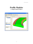
Program Overview
Overview
Thermwood's Five Piece Door application offers a means for creating five piece doors and drawer
fronts, as designed in Thermwood's eCabinet Systems software. Five piece doors consist of two
stiles, a left and a right, and two rails, a top and a bottom, as well as a center panel. This program
enables the designer to base their design on a standard library of door/drawer fronts, or to create
something totally unique. It is designed to take an output file (*.TWD format, generated from
eCabinet Systems), that contains a custom five piece door. Simply generate the CNC file from
any job or cabinet that contains a "build in house" five piece door/drawer front, and it will be
created, ready to be loaded into the Five Piece Door program at the Thermwood Machine.
Options are available in the application to designate the tooling to create a desired design shapes
for the bead, raise, and profile. A clamping fixture is utilized to hold the stiles and rails for
machining. A matted pad holds the panel for machining, and is also used with the assembled door
for perimeter machining. Parts can be filtered for processing for only those required at one time,
or the entire job can be run at once. Labels can be also created for each part during the "Write
CNC" process. Once the CNC file has been created, the machine can be started, and the operator
will be instructed through each step, guided by text provided on the machine control's screen. If
the next process to be completed is a rail or stile, the operator is informed of what size blank to
place in the clamps, as well as where to place the clamps.
2
Program Overview
Launching the Application
The Five Piece Door program is an application that runs on the Thermwood SuperControl. It is
launched from the main SuperControl screen by selecting "F11" <THM Options> and then "F6"
<Five Piece Door>. The Five Piece Door Main Window screen will appear now.
3
eCabinet Systems Information
eCabinet Systems Settings
In eCabinet Systems, selecting "Settings/Preferences" and then "Default 5 Piece Door For Cut
List", the following screen will appear:
NOTE: When using the "Build In House" option for vendor door/drawer fronts, it is important
to understand that what is displayed is just for reference. What you see graphically, and the
settings that are displayed here, and in the "Details for Cut List" area may not correspond. The
vendor door/drawer fronts will display with the rail and style widths and the material
color/texture(s) that are predetermined by the vendor's specifications.
NOTE: Be aware that the settings that display in the fields are general defaults and must be
confirmed to your application.
4
eCabinet Systems Information
eCabinet Systems Sizing Details for Cut List
Coping Depth
This is the distance to be added to the rails for coping into the stiles.
Perimeter Machining Allowance
This is the amount of material that will be added to the perimeter to true the door.
It should be noted that the stile and rail width will become narrower on the finished door by the
value that is entered here.
If this is not desired, the stile and rail width must be increased by this Perimeter Machining
Allowance amount to compensate.
Panel Inset
The center panel will be machined to allow it this distance inside the rail/stiles.
Panel Board Stock
The center panel will be made of this material. Confirm that the thickness is correct.
5
eCabinet Systems Information
Non-Thermwood Doors
Note that if you are using a Non-Thermwood door as the reference door, there are additional
settings needed to create the door. (Thermwood doors have these values set based on the selected
door).
NOTE: Remember that these settings are completely separate and do not reflect what is set in
the default five piece door "Details for Cut List".
Rail Width
This is the width of the rail, including the Perimeter Machining Allowance.
Stile Width
This is the width of the stile, including the Perimeter Machining Allowance.
Arch Height
This is the distance, from the widest part of the top rail, to the bottom of the arch.
Minor Rad. %
This value is used for cathedral doors only. It specifies the radius of the arcs that join the main
arch, as a percent of the radius of the main arch. If this amount is 100%, than the arc's radii are
identical.
Side Flat
The distance of material that is not curved, on either side of the main arc.
Top Flat
The straight (no arc) distance in the center of the main arc.
Stile and Rails Board Stock
The rails and stiles will be made from this material. Confirm correct material dimensions.
NOTE: All of the values listed above will be used for all doors in this job or cabinet; however,
individual overrides to these defaults can be made by selecting "Details for Cut List", in the
specific Door/Drawer Front Design screen.
6
eCabinet Systems Information
Reference Drawing for Non-Thermwood Doors
Top Rail shown.
7
eCabinet Systems Information
eCabinet Systems for Cut List Overrides
Specifying different door defaults
Individual overrides to the door default settings can be made by selecting "Details for Cut List", in
the specific Door/Drawer Front Designer screen. In this example, a Thermwood Standard
Cathedral Door is selected. Again, remember to select "Build In House" to use the Five Piece
Door program.
NOTE: When using the "Build In House" option for vendor door/drawer fronts, it is important
to understand that what is displayed is just for reference. What you see graphically, and the
settings that are displayed here and in the "Sizing Details for Cut List" area, may not
correspond. The vendor door/drawer fronts will display with the rail and style widths and the
material color/texture(s) that are predetermined by the vendor's specifications.
8
eCabinet Systems Information
eCabinet Systems Build In House
Door/Drawer Front Designer
NOTE: Doors will only show up in the Five Piece Door Program when the "Build In house"
option is selected!
9
Five Piece Door Program
Five Piece Door Main Window
Upon Launching the Program Application, you will see the following screen.
NOTE: The previous job's data will automatically be displayed when the Five Piece Door
program is loaded.
Menu Option Selections
On the top of the screen is a Windows Menu that provides the selection of the program options.
Starting from the left, the first menu option is "File".
File
Open
Provides a window where you can select the *.TWD file that you want to run. This will overwrite
any previously displayed job.
Exit
Closes the program completely.
10
Five Piece Door Program
Five Piece Door Main Window Settings
At each line there is a checkbox, and listed in descending order are the Door Name, the applicable
Cabinet Assembly, the Door Type and the list of components that will construct that door.
Note that if this job contains multiple doors, an additional list(s) of additional components will
follow directly below this one.
The checkboxes are used to deselect specific parts from the job. Green checks indicate that all
parts are selected and will be processed. Clicking on (for example, one of the rails or stiles), will
cause a yellow exclamation point marker to show in the Cabinet and Door Type selection area,
alerting you that this job will proceed, but will not be complete. Clicking anywhere above the
component list will cause a red "X" to be displayed, showing that this job will not be processed.
11
Five Piece Door Program
Tool Group Selection
Tool Group Selection
If you have created different Tool Groups, this option will enable selection of the Tool Group of
your choice. Otherwise, the
Default selection set will be used.
12
Five Piece Door Program
Machining Order
Machining Order of door parts
This option provides a choice in what order the parts are created. Depending on the type and
quantity of the job, it may be advisable to run the job in the order shown on screen, to run all the
stiles and rails first, or to run all of the panels first.
13
Five Piece Door Program
Units
Unit Selection
This switches program display from English (inches) to Metric (millimeters).
.
14
Five Piece Door Program
Required Job Quantity
Required Job Quantity
This display shows a tabulation of what amounts of doors and drawers are required for the loaded
job.
15
Five Piece Door Program
Write CNC and Cancel Buttons
CNC Write
This button outputs your job to a Thermwood CNC file. If the "CNC Quick Write" checkbox is
not enabled, you will be asked for a file name and a directory location to save this file. You will
then get a confirmation screen and an option to print labels to apply on your parts.
If you enter "Yes", you will get the label screen as shown below. Select the "Print" button to print
labels, and "Done" when they are finished.
NOTE: At this time, the CNC file for the parts will be loaded to the SuperControl, and will be
ready to run. Confirm that any offset locations, tooling, daylight values, etc. are set properly
before executing any part program, (including this one)!
Cancel
This button closes the program.
16
Five Piece Door Program
Edit
Settings/Preferences
Default CNC Save Path
This is where you can accept the default file location displayed, or browse for a different location
to save your data.
Enable CNC Quick Write Checkbox
If this box is checked, there will NOT be any warnings regarding the overwriting of any existing
files. This option saves time, but also gives no warning of any filename duplications, and will
overwrite the current default CNC file.
17
Five Piece Door Program
Tool Group Settings
Tool Group Settings Window
This menu option is where you will define the tools that will be used to run and complete this job.
Pay attention to the specific options that are available for each type of tool.
18
Five Piece Door Program
Tool Group Selection
Tool Groups
There will always be a default group, called "Generic". This file can not be deleted, and while it
can be modified, it is suggested that it is kept intact as a pattern file.
Copy
It is suggested that you use this button to create a new Tool Group, with a name of your choosing.
(In this sample image, one is created called "MRK").
Set To Default
This button enables you to select which tool group will be used as the default.
Add
This button allows creation of a new tool group. The initial values will be applied to it from the
program's original "Default" values.
Delete
This button removes the selected Tool Group.
19
Five Piece Door Program
Tool List
Tool List Section
This shows the available tools. Currently there are 7 tools, and they are listed below.
Bead Tool
This tool cuts the bead on the stiles and rails. For rough passes, it moves horizontally.
Raise Tool
This tool cuts the raise in the center panel. For rough passes, it moves vertically.
Profile Tool
This tool cuts the outer profile of the door. For rough passes, it moves vertically.
Cope Tool
This tool is used to cope the ends of the rails. For rough passes, it moves horizontally.
Top Rail Rough Tool
This tool is used on arched or cathedral rails to "rough out" the arch. For rough passes, it moves
vertically.
Panel Rough Tool
This tool sizes the center panel. For rough passes, it moves vertically.
Perimeter Sizing Tool
This tool cuts the door to the final dimensions. For rough passes, it moves vertically.
20
Five Piece Door Program
Basic Tool Information
Basic Tool Info
This section shows each tool's details, and allows the selection of the following parameters.
Tool Number
This is the number assigned to a particular tool for your Thermwood machine.
Lead In
This specifies the amount of distance used for the Lead In.
Lead Out
This specifies the amount of distance used for the Lead out.
Retract
This specifies the distance the tool retracts for indexing.
Rough Pass Amount
This specifies the distance increment for the Rough Pass[es].
Feed Speed
This is the specified feed speed, when cutting, in inches per minute or in millimeters per minute.
Spindle Speed
This is the specified spindle speed, in RPM.
WARNING! Ensure that you do not exceed the tool manufacturer's maximum RPM speed for
each tool!
Plunge Speed
This is the specified speed, in inches per minute or in millimeters per minute.
(#) Rough Passes
This specifies the amount of rough passes to be performed.
21
Five Piece Door Program
Lead In Speed
If blowout is occurring, you may want to slow the Lead In speed. Go to the section labeled
Change Lead In Speed
and check the box next to
Use Separate Lead In Speed.
You can now enter the desired Lead In Speed, in inches per minute, or in millimeters per minute,
in the area below
Lead In Speed.
22
Five Piece Door Program
Additional Tool Information
Additional Tool Info
This section enables you to set the other applicable variables.
Plunge Depth
The tool will plunge this distance.
Finish Amount
This is the amount of material that will remain for the finish pass.
Cut Through Depth
This is the distance that the tool will cut below the part's bottom face.
23
Five Piece Door Program
Fixtures
Fixture Settings
Fixtures
Fixture Settings
This window controls the specific settings that your Thermwood Machine needs to know
regarding your choice of fixtures, and their orientation.
24
Five Piece Door Program
Bead/Cope
Bead/Cope Section
This section allows the information to be set to create the stiles and rails.
Fixture Offset (G52L#)
This is the number code that defines the fixture offset.
X Shift Checkbox
Select this if you require an X Shift for the part's dimensions.
Y Shift Checkbox
Select this if you require a Y shift for the part's dimensions.
NOTE: Remember that an X or Y shift is based on the location of your fixture's origin, and the
fact that the part's origin is always the corner closest to Machine Home. If the location point of
the fixture is not in the part's corner closest to home, a shift will be required.
Z Fixture Adjust
This is the distance from the bottom of the part to the top of the spoilboard.
Clamp Location Offset
This is the distance from the end of your part, to the edge of the first inboard clamp, and is needed
to prevent a possible collision between the clamp(s) and the tool.
NOTE: You will also be prompted for clamp locations, based on this value, at the start of each
stile or rail job run.
Min. Stile/Rail Width
This sets the minimum allowable width limit for the stile/rails.
25
Five Piece Door Program
Fixture Orientation
Fixture Orientation Diagram
Fixture Orientation
It is important that you know where your origin, ("0, 0" point) is, and it is set here, as based on
your requirements. The options are:
Aligned with X (Left or Right)
and
Aligned with Y (Front or Back)
26
Five Piece Door Program
Tool Change Over Fixture
Tool Change Over Fixture Setting
If you desire to use this option, enable it by checking the box next to
Move to clearance position for tool change
and the enter the desired location (in inches or millimeters) next to
Y axis clearance position
NOTE: This feature ensures that there is no collision between any part of your work or fixture
while the tool change operation is occurring. Also note that this clearance position is
referenced from your Thermwood's Machine Home position!
27
Five Piece Door Program
Center Panel
This section allows the information to be set to create the center panel of your door. The options
available are:
Fixture Offset (G52L#)
This is the number code that defines the fixture offset.
X Shift Checkbox
Select this if you require an X Shift for the part's dimensions.
Y Shift Checkbox
Select this if you require a Y Shift for the part's dimensions.
NOTE: Remember that an X or Y shift is based on the location of your fixture's origin, and the
fact that the part's origin is always the corner closest to Machine Home. If the location point of
the fixture is not in the part's corner closest to home, a shift will be required.
Z Fixture Adjust
This is the distance from the bottom of the part to the top of the spoilboard.
Apply Collar Checkbox
Select this if you want to cut a collar in the panel. This is an offset amount from the origin of your
fixture, as the illustration shows:
Collar Amount
Enter the amount of collar desired.
28
Five Piece Door Program
Perimeter/Profile Settings
Perimeter/Profile
This section allows the information to be set to trim, true and complete your job. The options
available are:
Fixture Offset (G52L#)
This is the number code that defines the tool offset.
X Shift Checkbox
Select this if you require an X Shift for the part's dimensions.
Y Shift Checkbox
Select this if you require a Y Shift for the part's dimensions
NOTE: Remember that an X or Y shift is based on the location of your fixture's origin, and the
fact that the part's origin is always the corner closest to Machine Home. If the location point of
the fixture is not in the part's corner closest to home, a shift will be required.
Z Fixture Adjust
This is the distance from the bottom of the part to the top of the spoilboard.
Apply Collar Checkbox
Select this if you want to cut a collar in the completed door.
NOTE: The collar distance will be equal to the "Perimeter Machining Allowance" as shown
on the "Sizing Details for Cut List" screen:
29
Five Piece Door Program
Help
Help Menu
About
This feature shows details about the program and its revision level.
30
Five Piece Door Program
Running the CNC
When you have written the CNC file, the program is loaded and ready to run.
NOTE: At this time, the CNC file is loaded into the SuperControl, and will be ready to run.
Confirm that any offset locations, tooling, daylight values, etc. are set properly before
executing this program!
Pressing the START button on the SuperControl will execute the program, and you will
immediately see the following screen display.
After the first part has run, you will then see additional information in the blue area of the
SuperControl menu, alerting you that the next part is ready to be run.
31
Five Piece Door Program
And again, new information will appear in the blue area, until the door job is completed.
32
Glossary
B
bead: A rounded, raised profile, that is machined along the edge of a board.
C
collar: Distance that the finished door is offset from the origin of the fence. This allows for any
edge irregularities to be accounted for before the final perimeter machining pass.
cope: Coping is when the shape of one part is matched to the mating end of another part. Literally,
the "mirror image" of it, while allowing for fitting tolerances. In this case, where the rails
and stiles meet.
D
daylight: Refers to the distance from the tip of the bit to the surface of the spoilboard.
E
eCabinet Systems: Thermwood Corporation's software that is provided to eCabinet Systems
Members at no cost. It is a program established for custom cabinet and furniture design
and manufacturing shops. It features full "3-D" design capabilities for completing jobs
including cabinet boxes, dovetail drawers, doors (either MDF or five-piece raised panel
designs), and face frames. It then enables you to send the job to a Thermwood CNC router
where all these parts can be machined. The Thermwood CNC control takes the job from
the software and creates the nested based programs needed to make all the part.
Additionally it integrates your designs with suppliers and manufacturers of hardware,
moldings, finishes and even other designers. There, you can collaborate and offer for sale
your own successful projects, or browse a library of projects from other designers.
G
G52L#: Machine code for "Fixture Offset". This redefines the part's zero, relative to the machine
HOME. Replace the "#" with the actual value number. Note that this code will NOT
perform any machine motion.
L
lead in: An extra line programmed into the toolpath leading into the actual cut path of the part.
This is especially needed for tooling that will perform undercuts. If you start a tool with an
undercut directly on the part's finished path, it would destroy the part at the plunge
location.
lead out: An extra line programmed into the toolpath leading past the actual cut path of the part.
This is especially needed for tooling that will perform undercuts. If you end a tool with an
undercut directly on the part's finished path, it would destroy the part at the retract location.
33
Glossary
P
panel: The center piece of wood in the door. It is allowed to "float" freely between the styles and
rails. This allows the natural expansion and contraction of the wood to occur without
causing any cracking or distortion of the door. Panels can be flat or raised, depending on
the design.
plunge: Downward vertical movement of the tool.
profile: The pattern that is machined into the outer edges of the door.
R
rail: The horizontal member of the door. In an arched or cathedral door, the upper rail is machined
to achieve the required appearance.
raise: The cutting of the pattern in the center panel.
rough pass: A preliminary pass (or multiple passes) of the tool over the part, that ensures a clean
face for the final machining pass.
S
stile: The vertical members of the door frame.
SuperControl: Thermwood Corporation's high performance, CNC control system that is
configured to perform multiple axis motions simultaneously. It is a multi-processor system
with full multi-tasking capabilities. It is provided with all Thermwood CNC router
machines.
T
TWD file: Thermwood Corporation's database file for connecting eCabinet Systems CNC
information to their line of CNC routing machines.
34
Index
A
Additional Tool Information ...................... 23
Aligned with X........................................... 26
Aligned with Y........................................... 26
Application................................................... 3
Apply Collar Checkbox........................ 28, 29
arc................................................................. 6
Arch Height.............................................. 6, 7
B
Basic Tool Information .............................. 21
Bead Tool ................................................... 20
Bead/Cope .................................................. 25
Bead/Cope Section ..................................... 25
board........................................................... 20
board stock ................................................... 5
Build In House ................................. 2, 4, 8, 9
C
cabinet ............................................ 2, 4, 6, 11
Cabinet Assembly ...................................... 11
CANCEL Buttons ...................................... 16
Cathedral Door ............................................. 6
Center Panel ................................. 2, 5, 20, 28
center piece................................................. 28
Change Lead In Speed ............................... 22
Change Over Fixture .................................. 27
Checkbox ................................................... 11
clamp ............................................................ 2
Clamp Location Offset............................... 25
CNC ....................................................... 2, 31
CNC control system ............................... 3, 16
CNC file ..................................... 2, 16, 17, 31
CNC Quick Write checkbox ...................... 16
Collar Amount............................................ 28
color/texture ............................................. 4, 8
Cope Tool................................................... 20
coping........................................................... 5
Cut List....................................... 4, 5, 6, 8, 29
Cut List Overrides ........................................ 8
Cut Through Depth .................................... 23
D
Default CNC Save Path.............................. 17
deselect....................................................... 11
door ........................................................ 2, 28
door frame .................................................... 5
Door Type .................................................. 11
door/drawer ...................................... 2, 4, 8, 9
Door/Drawer Front Designer ................6, 8, 9
drawer front...................................................2
E
ECabinet Systems .............................2, 4, 8, 9
ECabinet Systems Build In House................9
ECabinet Systems Members .........................4
ECabinet Systems Settings ...........................4
ECabinet Systems Sizing ..............................5
ECabinet Systems V5.1 ................................4
edge .............................................................20
Edit..............................................................17
Enable CNC Quick Write Checkbox ..........17
English ........................................................14
F
F11 ................................................................3
F6 3
Feed Speed ..................................................21
Finish Amount ............................................23
Five Piece Door.............1, 2, 3, 6, 8, 9, 10, 11
Five Piece Door Main Window ..................10
Five Piece Door Main Window Settings ....11
Five Piece Door Program................2, 8, 9, 10
Fixture Offset ..................................25, 28, 29
Fixture Orientation......................................26
Fixture Orientation Diagram.......................26
Fixture Settings ...........................................24
Fixtures .....................2, 24, 25, 26, 27, 28, 29
G
G52L ...............................................25, 28, 29
Generic........................................................19
H
Help.............................................................30
Help Menu ..................................................30
I
including .......................................................6
increment.....................................................21
inset ...............................................................5
L
launching.......................................................3
lead in....................................................21, 22
Lead In Speed .............................................22
lead out........................................................21
Limit......................................................22, 25
List Section .................................................20
M
Machine Home..........................25, 27, 28, 29
35
Metric ......................................................... 14
Minor Rad .................................................... 6
Minor Radius................................................ 7
multi-processor................................. 3, 16, 31
N
Non-Thermwood Doors ........................... 6, 7
NOTE ............. 6, 8, 10, 16, 25, 27, 28, 29, 31
O
Option Selections ....................................... 10
overwrite .................................................... 10
P
Panel Board Stock ........................................ 5
Panel Inset .................................................... 5
Panel Rough Tool....................................... 20
Perimeter Machining Allowance............ 6, 29
Perimeter Sizing Tool ................................ 20
Perimeter/Profile ........................................ 29
Plunge Depth.............................................. 23
Plunge Speed.............................................. 21
Print ............................................................ 16
Profile Tool ................................................ 20
Program .................... 2, 10, 14, 16, 19, 30, 31
R
Rail Width ............................................ 5, 6, 7
Rail/stiles...................................................... 5
Rails Board Stock......................................... 6
Raise Tool .................................................. 20
Raised......................................................... 20
Required Job Quantity................................ 15
rough pass .................................................. 21
Rough Pass Amount................................... 21
Rough Passes.............................................. 21
rounded....................................................... 20
RPM ..................................................... 21, 22
S
Settings/Preferences ................................... 17
shift....................................................... 28, 29
Side Flat ................................................... 6, 7
Sizing Details ............................................. 29
Spindle Speed............................................. 21
spoilboard........................... 16, 25, 28, 29, 31
Index
START button.............................................31
stile width......................................................6
stile/rail width .............................................25
stile/rails......................................................25
SuperControl .....................................3, 16, 31
T
Thermwood ..1, 2, 3, 6, 10, 16, 21, 24, 25, 27,
28, 29, 31
Thermwood CNC..........................3, 4, 16, 31
Thermwood Corporation...............................1
Thermwood SuperControl ............................3
THM Options ................................................3
Tool Group Selection............................12, 19
Tool Group Settings....................................18
Tool Group Settings Window .....................18
Tool Groups ....................................12, 18, 19
toolpath .................................................21, 22
Top Flat.....................................................6, 7
Top Rail ..........................................2, 6, 7, 20
Top Rail Rough Tool ..................................20
TWD .............................................................2
TWD file .....................................................10
U
Unit Selection..............................................14
Units............................................................14
Use Separate Lead In Speed .......................22
V
vendor ...........................................................4
vertical members ...........................................5
W
WARNING .................................................21
Windows Menu...........................................10
wood..............................................................2
Write CNC ..................................................16
X
X Shift Checkbox............................25, 28, 29
Y
Y Shift Checkbox............................25, 28, 29
Z
Z Fixture Adjust..............................25, 28, 29
36