1
38
Chapter 2
Installation
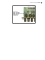
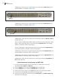
DB-9 (RS-232 and RS-422) Connectors
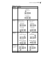
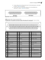
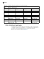
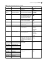
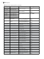
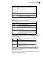
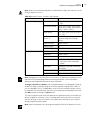
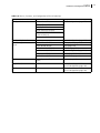
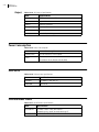
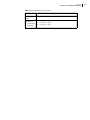
Table 2-8 ICONM-BO-V DB-9 Pinouts
Breakout
DB9 Pin
Port A
RS232
1
Port B, Port E
RS232 / RS422 Selectable
Port C
RS422
RS-232 Connection
RS-422
Connection
Frame Ground
Frame Ground
Frame Ground
Port D
RS232
2
TxD
RxD (Data received by
IconMaster)
Ta Tx- (Data sent by
IconMaster)
Ta Tx-
RxD
3
RxD
TxD (Data sent by
IconMaster)
Rb Rx+ (Data received by
IconMaster)
Rb Rx+
TxD
DTR (Data Terminal
Ready) *
Rc (Receiver Common or
Shield)
Ground
Ground
6
DSR (Data Serial Ready)
*
Tc (Transmit Common or
Shield)
7
RTS (Request to Send) ** Tb Tx+ (Data sent by
IconMaster)
Tb Tx+
8
CTS (Clear to Send) **
Ra Rx- (Data received by
IconMaster)
Ra Rx-
9
Frame Ground
Frame Ground
Frame Ground
4
5
GND
GND
* DB9 Pins 4 (DTR) and 6 (DSR) are connected internally to GND.
** DB9 Pins 7 (RTS) and 8 (CTS) are not used by IconMaster.
Note: RS-232 pinouts of port A are opposite to those of ports B, D, and E. The use of
straight-through versus null-modem cables must be carefully considered.