1
Installation and Configuration Manual
SPT
TM
SPT-LXYTOLIGHTWAVE Serial Protocol Translator
X-Y Control Of Lightwave Matrix-Hub Series 1000 Switcher
Edition B
LXYTOLITWVE MAN
Delivering the Moment
Publication Information
© 2014 Imagine Communications Corp. Proprietary and Confidential.
Imagine Communications considers this document and its contents to be proprietary and confidential.
Except for making a reasonable number of copies for your own internal use, you may not reproduce this
publication, or any part thereof, in any form, by any method, for any purpose, or in any language other
than English without the written consent of Imagine Communications. All others uses are illegal.
This publication is designed to assist in the use of the product as it exists on the date of publication of this
manual, and may not reflect the product at the current time or an unknown time in the future. This publication does not in any way warrant description accuracy or guarantee the use for the product to which it
refers.
Imagine Communications reserves the right, without notice to make such changes in equipment, design,
specifications, components, or documentation as progress may warrant to improve the performance of
the product.
Trademarks
SPT, CCS, CCS CoPilot, CCS Navigator, CCS Pilot, Command Control System, CineTone, CinePhase,
CineSound, DigiBus, DigiPeek, Digital Glue, DigiWorks, DTV Glue, EventWORKS, EZ HD, Genesis, HDTV
Glue, Image Q, Inca, Inca Station, InfoCaster, Inscriber, Inscriber CG—FX, Harris, Icon, IconLogo,
IconMaster, IconMaster Nav, IconSet, IconStation, Integrator, LeFont, Leitch, LogoMotion, MediaFile,
MIX BOX, NEO, the NEO design, NEOSCOPE, NewsFlash, Nexio, Opus, Panacea, PanelMAPPER, Platinum,
Portal, PROM-Slide, RouterMAPPER, RouterWORKS, Signal Quality Manager, SpyderWeb, SuiteView,
TitleMotion, UNIFRAME, Velocity, VelocityHD, VideoCarte, Videotek, and X75 are trademarks of Imagine
Communications or its subsidiaries. Microsoft® and Windows® are registered trademarks of Microsoft
Corporation.All other trademarks and trade names are the property of their respective companies.
Contact Information
Imagine Communications has office locations around the world. For locations and contact information see:
http://www.imaginecommunications.com/contact us/
Support Contact Information
For support contact information see:
▪▪
Support Contacts: http://www.imaginecommunications.com/services/technical support/
▪▪
eCustomer Portal: http://support.imaginecommunications.com
Preliminary—Contents are proprietary and confidential. Do not photocopy or distribute.
Contents
Preface
Manual Information.................................................................................................. v
Purpose .............................................................................................................. v
Audience............................................................................................................ v
Revision History................................................................................................ v
Writing Conventions ........................................................................................ vi
Obtaining Documents....................................................................................... vi
Unpacking/Shipping Information .......................................................................... vii
Unpacking a Product ....................................................................................... vii
Returning a Product......................................................................................... vii
Compliance and Safety Standards ........................................................................viii
Restriction on Hazardous Substances (RoHS) Compliance...........................viii
Waste from Electrical and Electronic Equipment
(WEEE) Compliance......................................................................................viii
Safety....................................................................................................................... ix
Safety Terms and Symbols in this Manual....................................................... ix
Chapter 1: Introduction
Applications Involving the SPT-LXYTOLIGHTWAVE ....................................... 2
Chapter 2: Installation
Installing the SPT-LXYTOLIGHTWAVE .............................................................. 3
Cable Wiring Details ............................................................................................... 5
Power Requirements ................................................................................................ 6
Chapter 3: Configuration and Assembly
Configuring the SPT-LXYTOLIGHTWAVE.......................................................... 9
RS-232/RS-422 Preference Settings ................................................................ 9
Level Offset ...................................................................................................... 9
DIP Switch and Jumper Settings .................................................................... 10
Reassembling the Unit ........................................................................................... 12
SPT-LXYTOLIGHTWAVE Installation and Configuration Manual
iii
Preliminary—Contents are proprietary and confidential. Do not photocopy or distribute.
Contents
Protocol Notes ....................................................................................................... 13
System and Matrix-Hub Discovery ................................................................ 13
Loss of Communication ................................................................................. 13
Detecting and Reporting Alarm Conditions ................................................... 14
Communication to Controller During Power Up ........................................... 15
Protocol Commands ....................................................................................... 15
Other Information ........................................................................................... 16
References ............................................................................................................. 18
Appendix A: Safety Precautions, Certifications, and
Compliances
Overview ................................................................................................................ 19
Safety Terms and Symbols in this Manual ............................................................ 20
Safety Terms and Symbols on the Product............................................................. 20
Preventing Electrostatic Discharge ........................................................................ 21
Injury Precautions................................................................................................... 21
Product Damage Precautions.................................................................................. 22
EMC and Safety Standards .................................................................................... 24
EMC Standards .............................................................................................. 24
Additional EMC Information ......................................................................... 25
Safety Standards ............................................................................................. 26
Index
Keywords ............................................................................................................... 27
iv
SPT-LXYTOLIGHTWAVE Installation and Configuration Manual
Preface
Manual Information
Purpose
This manual details the features, configuration details, and specifications for the
SPT-LXYTOLIGHTWAVE serial protocol translator.
Audience
This manual is written for technicians and operators responsible for installation,
setup, maintenance, and/or operation of the product, and is useful to operations
personnel for purposes of daily operation and reference.
Revision History
Table P-1. Manual Revision History
Edition
Date
Comments
Edition A
September 2002
Initial release
Edition B
June 2007
• Added power requirements information
• Added RoHS-WEEE compliance information
• Added index
SPT-LXYTOLIGHTWAVE Installation and Configuration Manual
v
Preface
Writing Conventions
To enhance your understanding, the authors of this manual have adhered to the
following text conventions:
Table P-2. Writing Conventions
Term or
Convention
Description
Bold
Indicates dialog boxes, property sheets, fields, buttons, check
boxes, list boxes, combo boxes, menus, submenus, windows,
lists, and selection names
Italics
Indicates email addresses, the names of books or publications,
and the first instances of new terms and specialized words that
need emphasis
CAPS
Indicates a specific key on the keyboard, such as ENTER, TAB,
CTRL, ALT, or DELETE
Code
Indicates variables or command-line entries, such as a DOS
entry or something you type into a field
>
Indicates the direction of navigation through a hierarchy of
menus and windows
hyperlink
Indicates a jump to another location within the electronic
document or elsewhere
Internet address
Indicates a jump to a website or URL
Note
Indicates important information that helps to avoid and
troubleshoot problems
Obtaining Documents
Technical documents can be viewed or downloaded from our website.
Alternatively, contact your Customer Service representative to request a
document.
vi
SPT-LXYTOLIGHTWAVE Installation and Configuration Manual
Preface
Unpacking/Shipping Information
Unpacking a Product
This product was carefully inspected, tested, and calibrated before shipment to
ensure years of stable and trouble-free service.
1. Check equipment for any visible damage that may have occurred during
transit.
2. Confirm that you have received all items listed on the packing list.
3. Contact your dealer if any item on the packing list is missing.
4. Contact the carrier if any item is damaged.
5. Remove all packaging material from the product and its associated
components before you install the unit.
Keep at least one set of original packaging, in the event that you need to return a
product for servicing.
Returning a Product
In the unlikely event that your product fails to operate properly, please contact
Customer Service to obtain a Return Authorization (RA) number, then send the
unit back for servicing.
Keep at least one set of original packaging in the event that a product needs to
be returned for service. If the original package is not available, you can supply
your own packaging as long as it meets the following criteria:
•
The packaging must be able to withstand the product’s weight.
•
The product must be held rigid within the packaging.
•
There must be at least 2 in. (5 cm) of space between the product and the
container.
•
The corners of the product must be protected.
Ship products back to us for servicing prepaid and, if possible, in the original
packaging material. If the product is still within the warranty period, we will
return the product prepaid after servicing.
SPT-LXYTOLIGHTWAVE Installation and Configuration Manual
vii
Preface
Compliance and Safety Standards
Appendix A: “Safety Precautions, Certifications, and Compliances” contains
product compliance and safety standards.
Restriction on Hazardous Substances (RoHS) Compliance
Directive 2002/95/EC—commonly known as the European Union (EU)
Restriction on Hazardous Substances (RoHS)—sets limits on the use of certain
substances found in electrical and electronic equipment. The intent of this
legislation is to reduce the amount of hazardous chemicals that may leach out of
landfill sites or otherwise contaminate the environment during end-of-life
recycling. The Directive takes effect on July 1, 2006, and it refers to the
following hazardous substances:
•
Lead (Pb)
•
Mercury (Hg)
•
Cadmium (Cd)
•
Hexavalent Chromium (Cr-V1)
•
Polybrominated Biphenyls (PBB)
•
Polybrominated Diphenyl Ethers (PBDE)
According to this EU Directive, all products sold in the European Union will be
fully RoHS-compliant and “lead-free.” (See our website for more information
on dates and deadlines for compliance.) Spare parts supplied for the repair and
upgrade of equipment sold before July 1, 2006 are exempt from the legislation.
Equipment that complies with the EU directive will be marked with a
RoHS-compliant emblem, as shown in Figure P-1.
Figure P-1. RoHS Compliance Emblem
Waste from Electrical and Electronic Equipment
(WEEE) Compliance
The European Union (EU) Directive 2002/96/EC on Waste from Electrical and
Electronic Equipment (WEEE) deals with the collection, treatment, recovery,
and recycling of electrical and electronic waste products. The objective of the
WEEE Directive is to assign the responsibility for the disposal of associated
hazardous waste to either the producers or users of these products. Effective
August 13, 2005, producers or users will be required to recycle electrical and
electronic equipment at end of its useful life, and may not dispose of the
equipment in landfills or by using other unapproved methods. (Some EU
member states may have different deadlines.)
viii
SPT-LXYTOLIGHTWAVE Installation and Configuration Manual
Preface
In accordance with this EU Directive, companies selling electric or electronic
devices in the EU will affix labels indicating that such products must be properly recycled. (See our website for more information on dates and deadlines for
compliance.) Contact your local sales representative for information on returning these products for recycling. Equipment that complies with the EU directive
will be marked with a WEEE-compliant emblem, as shown in Figure P-2.
Figure P-2. WEEE Compliance Emblem
Safety
Carefully review all safety precautions to avoid injury and prevent damage to
this product or any products connected to it. You will find a complete list of
safety precautions in Appendix A. Any user-serviceable components (such as
fuses or batteries) are only replaceable by those components listed in the
manual.
IMPORTANT! Only qualified personnel should perform service procedures.
Safety Terms and Symbols in this Manual
WARNING
Statements identifying conditions or practices
that may result in personal injury or loss of life.
High voltage is present.
CAUTION
Statements identifying conditions or practices
that can result in damage to the equipment or
other property.
SPT-LXYTOLIGHTWAVE Installation and Configuration Manual
ix
Preface
x
SPT-LXYTOLIGHTWAVE Installation and Configuration Manual
Chapter 1
Introduction
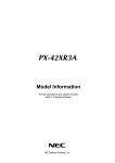
The SPT serial protocol translator is a compact adapter that translates between
Harris protocol and protocols used by other manufacturers or equipment. The
SPT can be used to integrate otherwise incompatible devices in a system, and it
may be used to expand a system beyond the normal limitations imposed by
hardware or system design. The SPT is available in several modes, each of
which is covered in a separate manual. For a complete list of available models,
refer to the SPT Applications Guide.
Figure 1-1. SPT Serial Protocol Translator
SPT-LXYTOLIGHTWAVE Installation and Configuration Manual
1
Chapter 1: Introduction
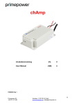
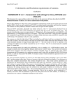
Applications Involving the SPT-LXYTOLIGHTWAVE
The SPT-LXYTOLIGHTWAVE may be used with a Harris routing switcher to
allow control of the switcher via automation system software written for the
Lightwave Matrix-Hub Series 10001 matrix switcher. The SPT translates X-Y
commands to Lightwave commands, and Lightwave responses to X-Y
responses. The Lightwave product interfaces to the SPT serial port, and X-Y
interfaces to the SPT X-Y BNC port. In this application, the SPT will translate
from Matrix-Hub protocol to the protocol required by the routing switcher (see
Figure 1-2).
12 34 56
SERIAL
VIDEO
OUTPUT
12 34 56
X-Y1
1
3
5
7
9
11
13
15
17
19
21
23
25
27
29
31
2
4
6
8
10
12
14
16
18
20
22
24
26
28
30
32
1
3
5
SYNC1
SERIAL
VIDEO
INPUT
232 422
7
9
11
13
15
17
19
21
23
25
27
29
31
2
4
6
8
10
12
14
16
18
20
22
24
26
28
30
32
1
3
5
7
9
11
13
15
17
19
21
23
25
27
29
31
2
4
6
8
10
12
14
16
18
20
22
24
26
28
30
32
1
3
5
1
ON
8 9
16
ON
ON
Off
232 422
SERIAL
VIDEO
INPUT
SERIAL
VIDEO
INPUT
SERIAL
VIDEO
INPUT
7
9
11
13
15
17
19
21
23
25
27
29
31
2
4
6
8
10
12
14
16
18
20
22
24
26
28
30
32
1
3
5
7
9
11
13
15
17
19
21
23
25
27
29
31
2
4
6
8
10
12
14
16
18
20
22
24
26
28
30
32
1
ON
SERIAL
VIDEO
INPUT
SERIAL
VIDEO
INPUT
SERIAL
VIDEO
OUTPUT
1
3
5
7
9
11
13
15
17
19
21
23
25
27
29
31
2
4
6
8
10
12
14
16
18
20
22
24
26
28
30
32
1
3
5
7
9
11
13
15
17
19
21
23
25
27
29
31
2
4
6
8
10
12
14
16
18
20
22
24
26
28
30
32
1
3
5
7
9
11
13
15
17
19
21
23
25
27
29
31
2
4
6
8
10
12
14
16
18
20
22
24
26
28
30
32
8 9
ON
16
ON
Off
RCP-p series
router control panels
Integrator™ frame
X-Y
SPT
Serial Protocol Translator
SPT-LXYTOLIGHTWAVE
Serial protocol translator provides conversion from
Lightwave protocol to X-Y protocol
Matrix Control RS-232-C In
Lightwave Communications
A LANTRONIX® Company
Series 1000
Matrix-Hub Series 1000
matrix switcher
Figure 1-2. Interfacing to Matrix-Hub Series 1000 Control System
1 The
Lightwave Matrix-Hub Series 1000 matrix switch is a product of Lightwave
Communications, Milford Connecticut.
2
SPT-LXYTOLIGHTWAVE Installation and Configuration Manual
Chapter 2
Installation
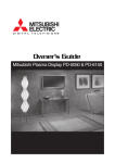
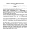
Installing the SPT-LXYTOLIGHTWAVE
The SPT-LXYTOLIGHTWAVE is installed in the control line (see Figure 2-1).
•
The maximum allowable distance for each segment of the X-Y coaxial
cable run is 2,000 ft (609 m).
•
The maximum length for each RS-422 segment is 2,000 ft (609 m).
•
The maximum length for each RS-232 segment is 50 ft (15 m).
There is no limit to the number of control devices added to the X-Y control bus.
SPT-LXYTOLIGHTWAVE Installation and Configuration Manual
3
Chapter 2: Installation
12 34 56
SERIAL
VIDEO
OUTPUT
12 34 56
X-Y1
1
3
5
7
9
11
13
15
17
19
21
23
25
27
29
31
2
4
6
8
10
12
14
16
18
20
22
24
26
28
30
32
1
3
SYNC1
SERIAL
VIDEO
INPUT
232 422
7
9
11
13
15
17
19
21
23
25
27
29
31
2
4
6
8
10
12
14
16
18
20
22
24
26
28
30
32
1
3
5
5
7
9
11
13
15
17
19
21
23
25
27
29
31
2
4
6
8
10
12
14
16
18
20
22
24
26
28
30
32
1
3
5
7
9
11
13
15
17
19
21
23
25
27
29
31
2
4
6
8
10
12
14
16
18
20
22
24
26
28
30
32
1
ON
8 9
16
ON
ON
Off
232 422
SERIAL
VIDEO
INPUT
SERIAL
VIDEO
INPUT
1
SERIAL
VIDEO
INPUT
3
5
7
9
11
13
15
17
19
21
23
25
27
29
31
2
4
6
8
10
12
14
16
18
20
22
24
26
28
30
32
1
3
5
7
9
11
13
15
17
19
21
23
25
27
29
31
2
4
6
8
10
12
14
16
18
20
22
24
26
28
30
32
1
ON
SERIAL
VIDEO
INPUT
SERIAL
VIDEO
INPUT
SERIAL
VIDEO
OUTPUT
1
3
5
7
9
11
13
15
17
19
21
23
25
27
29
31
2
4
6
8
10
12
14
16
18
20
22
24
26
28
30
32
1
3
5
7
9
11
13
15
17
19
21
23
25
27
29
31
2
4
6
8
10
12
14
16
18
20
22
24
26
28
30
32
8 9
ON
16
ON
Off
RCP-p series
router control panels
Integrator™ frame
X-Y
SPT
Serial Protocol Translator
SPT-LXYTOLIGHTWAVE
Serial protocol translator provides conversion from
Lightwave protocol to X-Y protocol
Matrix Control RS-232-C In
Lightwave Communications
Series 1000
A LANTRONIX® Company
Matrix-Hub Series 1000
matrix switcher
Figure 2-1. Connecting the SPT-LXYTOLIGHTWAVE
1
6
5
9
DB-9 Male
Port Configured For RS-232
Pin
1
2
3
4
5
6
7
8
9
Function
RxD (data received by router)
TxD (data sent by router)
Ground
Figure 2-2. Serial Connector Pin Assignments
4
SPT-LXYTOLIGHTWAVE Installation and Configuration Manual
Chapter 2: Installation
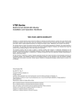
Cable Wiring Details
The Matrix-Hub is shipped with an RS-232C straight-through cable included.
Figure 2-3 shows the connector pin assignments on both ends of the connection
and the cable wiring description is shown in-between the connectors.
Figure 2-3. Cable Wiring Details for SPT-LXYTOLIGHTWAVE
SPT-LXYTOLIGHTWAVE Installation and Configuration Manual
5
Chapter 2: Installation
Power Requirements
Locations with 110-127 Volt Electrical Systems
Note
Locations with 110-127 volt electrical systems should use the PD9200PL6A
adaptor.
If you did not receive the correct
adaptor for your electrical system, please contact your Customer Service representative.
See our website for contact
information for our service centers worldwide.
Figure 2-4. PD9200PL6A Adaptor
6
•
Input voltage: 120 VAC, 60 Hz
•
Input current: 60 mA max.
•
Output voltage: 9.0 VDC
•
Output current: 200 mA
•
Output connector: 5.5 mm×2.5 mm female barrel power plug with positive
center (see Figure 2-4)
SPT-LXYTOLIGHTWAVE Installation and Configuration Manual
Chapter 2: Installation
Locations with 220-240 Volt Electrical Systems
Locations with 220-240 volt electrical systems should use the PD9300EPL6A
adaptor.
Figure 2-5. D9300EPL6A Adaptor
•
Input voltage: 230 VAC, 5 0Hz
•
Input current: 40 mA max
•
Output voltage: 9.0 VDC
•
Output current: 30 0mA
•
Output connector: 5.5 mm×2.5 mm female barrel power plug with positive
center (see Figure 2-5)
SPT-LXYTOLIGHTWAVE Installation and Configuration Manual
7
Chapter 2: Installation
8
SPT-LXYTOLIGHTWAVE Installation and Configuration Manual
Chapter 3
Configuration and Assembly
Configuring the SPT-LXYTOLIGHTWAVE
Note
In the unlikely event that you
need to change settings, see
Figure 3-1 and Figure 3-2 for
more information on these
settings.
The SPT-LXYTOLIGHTWAVE is shipped from the factory preconfigured for
use. In most cases, it will not be necessary to reconfigure the SPT. The
following parameters, however, are user-configurable:
Table 3-1. Settings
User-Configurable Setting
Factory Default Setting
RS-422 jumper switch
RS-232
Serial port baud rate
9600 baud
X-Y on XLR termination (the XLR ports
must be terminated if the SPT is located
at the end of the bus)
Terminated
SPT Address (ID)
1
RS-232/RS-422 Preference Settings
The serial port level of the Matrix-Hub handles both RS-232 and RS-422
connections, but only one or the other at a time can be used for a source's level.
One DIP switch will be required to express RS-232/RS-422 preference. See
Figure 3-2 for an illustration.
Level Offset
The SPT-LXYTOLIGHTWAVE uses four levels. Those levels are consecutive
in the following order:
•
Video
•
Mouse and Keyboard
•
Serial Port
•
Other
The four levels can either be enumerated as the top four levels (4-7), or the
bottom four levels (0-3) with the level offset DIP switch. See Figure 3-2 for an
illustration.
SPT-LXYTOLIGHTWAVE Installation and Configuration Manual
9
Chapter 3: Configuration and Assembly
DIP Switch and Jumper Settings
Configuration is accomplished via DIP switch and jumper settings, as shown in
Figure 3-1 and Figure 3-2.
Jumper Pack (SW3)
Orientation
U5 Firmware Identification
RS-232 (Default)
Firmware Type
.Must be SPT22 for LXYTOLIGHTWAVE
application (contact Customer Service if
firmware type is not SPT22)
Firmware Level
Varies as new releases are developed
Checksum
Varies as new releases are developed
J5
J8
S147ECSH
SW2
J10
J9
SW1
Suitcase Jumpers
Jumper
Setting
Designator
J5
Not installed
J6
Not installed
J7
Not installed
J8
Not installed
J9
Not installed
J10
Not installed
Important
To ensure proper Identification of
new parameters, update the label on
the back of the SPT whenever you
modify any switch or jumper settings
Figure 3-1. DIP Switch and Jumper Locations
10
SPT-LXYTOLIGHTWAVE Installation and Configuration Manual
Chapter 3: Configuration and Assembly
Figure 3-2. DIP Switch Settings
SPT-LXYTOLIGHTWAVE Installation and Configuration Manual
11
Chapter 3: Configuration and Assembly
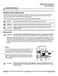
Reassembling the Unit
To avoid damage to the SPT-LXYTOLIGHTWAVE circuitry, the unit must be
reassembled as shown in Figure 3-3. Note that one of the four standoffs on the
underside of the bottom cover has been removed. Orient the cover so that this
area is positioned directly over U1. If U1 is positioned under an intact standoff,
the standoff will press against the component, and possibly cause damage to the
unit.
XY
COAX
XLR
Rear
Slot
Removed
Stand-off
Front
Slot
Power
Control
9-pin “D”
connector
X-Y
Direction
RS-232 @ 9600 Baud
SPT-LXYTOLIGHTWAVE V2.10
X-Y on coax
or mini-XLR
Note: If changes are made to the settings
inside of this unit, remember to
update the label for future reference.
Figure 3-3. Reassembling the Unit
12
SPT-LXYTOLIGHTWAVE Installation and Configuration Manual
Chapter 3: Configuration and Assembly
Protocol Notes
The SPT-LXYTOLIGHTWAVE protocol is an RS-232 protocol. When the
SPT-LXYTOLIGHTWAVE is powered up, it requires approximately 4 seconds
to update the internal status table.
System and Matrix-Hub Discovery
System Discovery
SPT-LXYTOLIGHTWAVE supports the discovery of a new Matrix-Hub router,
and the loss of communication with the previously discovered Matrix-Hub.
SPT-LXYTOLIGHTWAVE will also query and report alarms for the connected
Matrix-Hub.
Matrix-Hub Discovery
The SPT-LXYTOLIGHTWAVE will go into a discovery sequence on startup.
During the discovery sequence the unit will establish the frame size, and
crosspoint connects of the connected Matrix-Hub. Crosspoint information will
then be relayed back to X-Y.
The SPT-LXYTOLIGHTWAVE will remain in discovery until the following
events complete:
Note
The default password (mh1) is
case-sensitive. The system will
not respond to the default
password if it is entered in
all-caps or caps-lowercase.
1. The Lightwave unit accepts and responds to the default password “mh1.”
2. A Lightwave CL message is sent to the Matrix-Hub to query frame size.
3. A Lightwave CL response message is received to indicate the frame size are
received.
4. The frame size is sent on X-Y.
5. A Lightwave CS message is sent for each level found during frame size
discovery to query crosspoints at each level.
6. A Lightwave CS response is received for each level queried.
7. Data from each crosspoint disclosed in the CS response message is sent via
an S: message to X-Y.
Loss of Communication
The SPT-LXYTOLIGHTWAVE will detect when the previously discovered
Matrix-Hub has been disconnected. Upon detection the SPT will transmit a
series of frame size messages indicating the change (typically, “frame size 0”).
SPT-LXYTOLIGHTWAVE Installation and Configuration Manual
13
Chapter 3: Configuration and Assembly
Detecting and Reporting Alarm Conditions
Note
See “Protocol Commands” on
page 15 for descriptions of the
commands and messages
described in this section
Unlike Harris products, the Lightwave Matrix-Hub will not send the bus
unsolicited alarm messages when an alarm occurs. To simulate operation as a
Harris router, the SPT-LXYTOLIGHTWAVE will periodically send the
Lightwave CP <Level> command to query for alarms.
1. After receiving the solicited CP response the message is parsed. If an alarm
condition exists:
•
The alarm value is stored in the event that X-Y solicits for alarms later
with the Q? message.
•
An unsolicited Q: alarm with the new alarm information is sent back on
X-Y.
2. Matrix-Hub CP response messages will be in the following formats:
2PP1,Power Supply A +5V: OK
2PP1,Power Supply A -5V: OK
2PP0,Power Supply B +5V: Failed
2PP0,Power Supply B -5V: Failed
2PT 95ßF
2PT 97ßF
2PT 91ßF
3. The SPT will convert Matrix-Hub status messages to alarm messages as
follows:
•
If Power Supply A fails, the value “4” will be bit-masked into the alarm
message. Within Harris router control applications, this alarm value will
correspond to the Harris alarm “Power Supply 1 Failure.”
•
If Power Supply B fails, the value “8” will be bit-masked into the alarm
message. Within Harris router control applications, this alarm value will
correspond to the Harris alarm “Power Supply 2 Failure.”
•
If a temperature value exceeds 100° (either Centigrade or Fahrenheit),
the value “1” will be bit-masked into the alarm message. Within Harris
router control applications, this alarm value will correspond to the
alarm “Fan 1 Failure.”
IMPORTANT: Lightwave Communications has indicated that
temperatures above 100°F may be a concern, since at this temperature
VGA output may start to become distorted. However, in trial runs at
Harris, standard operating temperatures often exceed this value.
The elevated temperature may have little to do with an actual “Fan”
malfunction in the Matrix-Hub. Currently, Harris has no alarm value to
indicate elevated temperature. The temperature has been arbitrarily
mapped to the Fan alarm, as a closest match solution.
The temperature alarm condition is not dependent on the style of
measurement (i.e., Centigrade, Fahrenheit), only that the units meet or
exceed 100. You can disable this alarm by running the Lightwave with
14
SPT-LXYTOLIGHTWAVE Installation and Configuration Manual
Chapter 3: Configuration and Assembly
“Display Temperature in °C” mode. This mode is enabled by adjusting
the DIP switches in the Matrix-Hub control card (see “Other
Information” on page 16).
For more information on the contents of the CP response message see the
Matrix-Hub Series 1000 User Manual.
Communication to Controller During Power Up
Communications with the SPT-LXYTOLIGHTWAVE will not begin until the
discovery sequence completes. The discovery sequence cannot complete if there
is no Matrix-Hub detected.
Protocol Commands
Commands Handled Between X-Y and SPT-LXYTOLIGHTWAVE1
The SPT-LXYTOLIGHTWAVE protocol supports the following X-Y
commands:
Table 3-2. X-Y Commands Supported by SPT-LXYTOLIGHTWAVE Protocol
Command Syntax
(command begins with “@” sign
followed by a space)
Command Name
Result
@ Q?
Alarms Request
Requests status of all alarms in
system
@ B:C
Clear Preset Buffer
Clears all presets
@ I?A
Device Description Request
Device information description
@ I?T
Device Type Request
Device type information
@ I?V
Device Version Request
Device version information
@ X:<Lvls>/<Dest>,<Src>[:I<ID>]
Direct Crosspoint Take
Takes specified crosspoint
(specifies source, destination, and
level) without buffer execute
command
@ B:E
Execute Preset Buffer
Executes all presets
@ F?<Lvl>
Frame Size Request
Requests router size on a specific
level
@ P:<Lvl>/<Dest>,<Src>[:I<ID>]
Preset Crosspoint
Presets or preloads crosspoint
requests for execution at a later
time
@ S?<Lvls>
Request Crosspoint Status– Entire
Level
Requests crosspoint status of all
destinations on a specified level
1 You must be in Pass-Through Protocol mode to execute these X-Y commands. See the Serial Protocol Reference Guide for more
information about pass-through protocol commands.
SPT-LXYTOLIGHTWAVE Installation and Configuration Manual
15
Chapter 3: Configuration and Assembly
Table 3-2. X-Y Commands Supported by SPT-LXYTOLIGHTWAVE Protocol (Continued)
Command Syntax
(command begins with “@” sign
followed by a space)
Command Name
Result
@ X?<Lvl><Dest>
Request Crosspoint Status – Single
Destination
Requests crosspoint status of a
specific destination on a specific
level
@ P?<Lvl><Dest>
Request Preset Crosspoint Status
Verifies source that has been preset
to a given destination on a specific
level
@ V?<Lvl>
Request Preset Crosspoint Status On
Level
Verifies source that has been preset
to any destination on a given level
@ Z:<Lvls>
Reset Levels
Simulates a reboot of the SPT
@ B:R
Reset Preset Buffer
Resets or clears all presets
(replaced in most products with @
B:C Clear Preset)
Commands Issued Between SPT-LXYTOLIGHTWAVE and Matrix-Hub
The following commands are supported internally in transactions between the
SPT-LXYTOLIGHTWAVE and the Matrix-Hub. The user does not call these
commands directly over X-Y.
Table 3-3. Lightwave Matrix-Hub Commands
Command Syntax
Result
CL
Lists all chassis cards in inventory
CP
List of power supply and temperature status
CS
List of active connections
C
Connects input port to output port
D
Disconnects input port from output port
Other Information
16
•
The SPT will support a matrix of up to 128 sources by 128 destinations on 4
levels.
•
Currently, the only point of entry for control of the Matrix-Hub Series 1000
switcher is the Matrix-Hub serial “in” port. The SPT-LXYTOLIGHTWAVE
assumes sole control of the Matrix-Hub system. Future enhancements in
control schemes that may be developed to use more than one controller will
have adverse effects on the performance of the SPT-LXYTOLIGHTWAVE,
and are not recommended.
•
The SPT-LXYTOLIGHTWAVE assumes control of a maximum of four
switching levels. When used in conjunction with a Harris router system the
Harris system cannot use more than four levels.
SPT-LXYTOLIGHTWAVE Installation and Configuration Manual
Chapter 3: Configuration and Assembly
•
In the native mode of operation Matrix-Hub has default user privilege
levels. When used with the SPT-LXYTOLIGHTWAVE the Matrix-Hub
password user levels will be inherently determined by your ability to log
onto the workstation running the RouterWorks® application.
•
The Matrix-Hub allows a source to be taken to multiple destinations on the
monitor level, but not on other levels. As a result, if a keyboard, mouse, or
serial port is taken to multiple destinations, only the last destination
specified in the command (or in the preset buffer) will be taken on these
levels. Other conflicting destination levels will be left disconnected.
•
Successful use of the Matrix-Hub with the SPT-LXYTOLIGHTWAVE
requires that you configure the Matrix-Hub DIP switch settings as per the
Matrix-Hub Series 1000 User Manual. Additionally, you must configure the
optional user preference settings as shown in Table 3-4.
Table 3-4. Optional User Preference Settings
Matrix-Hub DIP
Switch Position
DIP Switch Settings
Feature Result
SW2, Poles 1-8
00000000 = 19200 baud
OR
00000010 = 9600 baud
OR
11000001 = 4800 baud
Baud rate must match SPT
baud
SW3, Pole 1*
0*
Display temperature in °F*
SW3, Pole 2
1
Echo characters ON
SW3, Pole 3
1
Send error messages
SW3, Pole 4
0
Do not add line feed to outputs
* To disable temperature alarm, set to “1.”
SPT-LXYTOLIGHTWAVE Installation and Configuration Manual
17
Chapter 3: Configuration and Assembly
References
The following documentation used the following references for implementing
the protocol translation:
Matrix-Hub Series 1000 User Manual, 13 July 2001, Lightwave
Communications (© 1999-2000, Lightwave Communications, Inc., 100
Washington Street, Milford CT 06460)
Serial Protocol Reference Operation and Reference Manual, Edition C (© July
2002)
18
SPT-LXYTOLIGHTWAVE Installation and Configuration Manual
Appendix A
Safety Precautions, Certifications, and
Compliances
Overview
Carefully observe the safety alert symbols below for dangers, warnings, and
cautions. They alert installers and operators of possible dangers or important
information contained in this manual.
Keep in mind, though, that warnings alone do not eliminate hazards, nor are
they a substitute for safe operating techniques and proper accident prevention
measures.
Any user-serviceable components (such as fuses or batteries) are only
replaceable by those components listed in the manual.
IMPORTANT! Only qualified personnel should perform service procedures.
SPT-LXYTOLIGHTWAVE Installation and Configuration Manual
19
Appendix A: Safety Precautions, Certifications, and Compliances
Safety Terms and Symbols in this Manual
WARNING
Statements identifying conditions or practices
that may result in personal injury or loss of life.
High voltage is present.
CAUTION
Statements identifying conditions or practices
that can result in damage to the equipment or
other property.
Safety Terms and Symbols on the Product
DANGER: High voltage and indicates a personal injury hazard
immediately accessible as one reads the marking.
WARNING: Indicates a personal injury hazard not immediately
accessible as one reads the marking.
CAUTION: Indicates a hazard to property, including the product, or to
pay attention and refer to the manual.
Protective ground (earth) terminal.
Fuse. Replace with same type and rating of fuse.
Zur Vermeidung von Feuer verwenden Sie nur Sicherungen mit der für
dieses Produkt geforderten Typ und Stromstärke.
20
SPT-LXYTOLIGHTWAVE Installation and Configuration Manual
Appendix A: Safety Precautions, Certifications, and Compliances
Preventing Electrostatic Discharge
Observe precautions for handling electrostatic sensitive devices.
CAUTION: Electrostatic discharge (ESD) can damage components in
the product. To prevent ESD, observe these precautions when directed
to do so:
1. Use a Ground Strap. Wear a grounded antistatic wrist strap to discharge the
static voltage from your body while installing or removing sensitive
components.
2. Use a Safe Work Area. Do not use any devices capable of generating or
holding a static charge in the work area where you install or remove
sensitive components. Avoid handling sensitive components in areas that
have a floor or benchtop surface capable of generating a static charge.
3. Handle Components Carefully. Do not slide sensitive components over any
surface. Do not touch exposed connector pins. Handle sensitive components
as little as possible.
4. Transport and Store Carefully. Transport and store sensitive components in
a static-protected bag or container.
Injury Precautions
WARNING
Potentially lethal voltages are present within the frame during normal
operation. The AC power cord must be disconnected from the frame before
the top panel is removed. (In frames with multiple power supplies, remove
ALL power cords.) Power should not be applied to the frame while the top
is open unless properly trained personnel are servicing the unit.
Pull out the plug from the main socket before the removal of a cover.
Przod zdjeciem pokrywy wyciagnac wtyczke z gniazda sieciowego.
WARNING: SHOCK HAZARD - DO NOT OPEN.
AVIS: RISQUE DE CHOC ÉLECTRIQUE - NE PAS OUVRIR.
MOUNT IN RACK ONLY
INSTALLER SUR SUPPORT DE MONTAGE SEULEMENT.
Use proper power cord
To avoid fire hazard, use only the power cord specified for this product.
SPT-LXYTOLIGHTWAVE Installation and Configuration Manual
21
Appendix A: Safety Precautions, Certifications, and Compliances
Ground the product
This is a Safety Class 1 product and is grounded through the grounding
conductor of the power cord. To avoid electrical shock, the grounding
conductor must be connected to earth ground. Before making connections
to the product’s input or output terminals, ensure the product is properly
grounded.
WARNING: THIS APPLIANCE MUST BE GROUNDED.
WARNING: THIS APPLIANCE MUST BE EARTHED.
VARNING: APPARATEN SKALL ANSLUTAS TILL JORDAT UTTAG
NÄR DEN ANSLUTS TILL ETT NÄTVERK.
Do Not Operate Without Covers
To avoid electrical shock or fire hazard, do not operate this product with
covers or panels removed.
Use Proper Fuse
To avoid fire hazard, use only the fuse type and rating specified for this
product.
Do Not Operate in Wet/Damp Conditions
To avoid injury or fire hazard, do not operate this product in wet or damp
conditions.
Do Not Operate in an Explosive Atmosphere
To avoid injury or fire hazard, do not operate this product in an explosive
atmosphere.
Avoid Exposed Circuitry
To avoid injury, remove jewelry such as rings, watches, and other metallic
objects. Do not touch exposed connections and components when power is
present.
Product Damage Precautions
CAUTION:
Disconnect power from the frame before removing or installing input/
output modules. Removing or installing modules with power applied could
cause serious damage to system components.
Use Proper Power Source
Do not operate this product from a power source that supplies more than the
specified voltage.
Use Proper Voltage Settings
Before applying power, ensure that the line selector is in the proper position
for the power source being used.
22
SPT-LXYTOLIGHTWAVE Installation and Configuration Manual
Appendix A: Safety Precautions, Certifications, and Compliances
Provide Proper Ventilation
To prevent product overheating, provide proper ventilation.
Do Not Operate With Suspected Failures
If you suspect there is damage to this product, have it inspected by qualified
service personnel.
CAUTION: This unit can have more than one power supply cord. To
de-energize the internal circuitry, you have to disconnect all power cords.
ADVARSEL: Utstyret kan ha mere ennn en tilførselsledning. For å gjore
interne deler spennigsløse må alle tilførselsledningene trekkes ut.
VARNING: Denna apparat har mer än en nätanslutning. Samtliga nätkablar
måste bortkopplas för att göra de interna kretsarna spänningsfria.
FUSE: REPLACE WITH SAME TYPE AND RATING OF FUSE.
CAUTION: REPLACE WITH SAME TYPE FUSE.
ATTENTION: UTILISER UN FUSIBLE DE RECHANGE DE MÊME
TYPE.
CAUTION: DISCONNECT SUPPLY CORD BEFORE CHANGING
FUSE.
ATTENTION: DÉBRANCHER AVANT DE REMPLACER LE
FUSIBLE.
ACHTUNG: VOR AUSWECHSELN DER SICHERUNG IST DAS
GERÄT VOM NETZ ZU TRENNEN.
CAUTION
Disconnect power from the frame before removing or installing input/
output modules. Removing or installing modules with power applied could
cause serious damage to system components.
Use Proper Power Source
Do not operate this product from a power source that supplies more than the
specified voltage.
SPT-LXYTOLIGHTWAVE Installation and Configuration Manual
23
Appendix A: Safety Precautions, Certifications, and Compliances
EMC and Safety Standards
This product has been tested and found to comply with the following
IEC, FCC, UL, ICES, and CSA standards, per the provision of the
Electromagnetic Compatibility Directive 89/336/EEC of 3 May 1989 as
amended by 92/31EEC of 28 April 1992 and 93/68/EEC, Article 5 of 22
July 1993, and the Low Voltage Directive 73/23/EEC of 19 February
1973.
EMC Standards
Table A-1. EMC Standards
EMC Standard
Description
EN55014
Limits and Methods of Measurement of Radio Disturbance Characteristics of Electric
Motor-Operated and Thermal Appliances for Household and Similar Purposes,
Electric Tools, and Similar Electric Apparatus
EN55022
Limits and Methods of Measurement of Radio Disturbance Characteristics of
Information Technology Equipment-Class A
EN55103-1
Electromagnetic Compatibility — Product Family Standard for Audio, Video,
Audio-Visual, and Entertainment Lighting Control Apparatus for Professional Use —
Part 1: Emission, Environment E4
EN55103-2
Electromagnetic Compatibility — Product Family Standard for Audio, Video,
Audio-Visual, and Entertainment Lighting Control Apparatus for Professional Use —
Part 2: Immunity, Environment E4
EN61000-3-2
Limits for Harmonic Current Emissions (Equipment Input Current Less Than or Equal
to 16 A Per Phase)
EN61000-3-3
Limitations of Voltage Fluctuations and Flicker in Low Voltage Supply Systems for
Equipment with Rated Current Less Than 16 A
EN61000-4-2
Electrostatic Discharge Requirements “ESD” 2 kV CD, 4 kV AD
EN61000-4-3
Radiated Radio-Frequency Electromagnetic Field Immunity Test 1 V/m {1 kHz 80%
AM, 80-1000 MHz}
EN61000-4-4
Electrical Fast Transient Requirements “Burst,” 0.5 kV Sig. & Ctrl. Lines 0.5 kV a.c.
& d.c. Power Line, 0.5 kV Functional Earth
EN61000-4-5
Surge Immunity Test 0.5 kV a.c. Power Line
EN61000-4-6
Immunity to Conducted Disturbances Induced by Radio Frequency Fields 1 V rms
0.15-80 MHz Sig. & Ctrl. Lines, 3 V rms 0.15-80 MHz d.c. Power Line, 1 V rms
0.15-80 MHz a.c. Power Line, 1 V rms 0.15-80 MHz Functional Earth
EN61000-4-11
Voltage Dips, Short Interruptions, and Voltage Variations- Immunity Tests
24
SPT-LXYTOLIGHTWAVE Installation and Configuration Manual
Appendix A: Safety Precautions, Certifications, and Compliances
These devices are for professional use only and comply with Part 15 of
FCC rules. Operation is subject to the following two conditions:
1. These devices may cause interference to radio and TV receivers in
residential areas.
2. These devices will accept any interference received, including
interference that may cause undesired operations.
Changes or modifications not expressly approved by Harris Corporation,
the party responsible for compliance to the FCC Part 15 Rule, could void
the user’s authority to operate this equipment legally in the United States.
These devices do not exceed the Class A limits for radio noise emissions
from digital apparatus as set out in the interference standard entitled
“Digital apparatus,” ICES-003 of the Canadian Department of
Communications.
Additional EMC Information
This device is for professional use in a controlled EMC environment, such as
purpose-built broadcast studios.
EMC regulations require that the radiation emitted from this unit does not
exceed certain limits. These limits are only met when the front panel is closed
and the two thumb screws are secured.
Compliance to the EMC regulations is also dependent on the use of suitably
shielded (screened) cables. Coax cables should be of the double-shielded
(screened) variety. Unused BNCs should be fitted with 75Ω terminations.
All audio cables should be screened with the shield (screen) making good
contact with the metallic parts of the cable connectors.
D-type connectors used with this unit should always have metallic shells with
the shield (screen) of the cable mechanically bonded to the metal shell. It is
further recommended that the D-type cable connectors be of the “dimple”
variety. These connectors make a better contact and consequently improve EMC
performance.
SPT-LXYTOLIGHTWAVE Installation and Configuration Manual
25
Appendix A: Safety Precautions, Certifications, and Compliances
Safety Standards
Table A-2. Harmonized and Reference IEC Safety Standards
Harmonized Standard
Reference IEC Standard
Description
EN 60950:1992 with
Am1, Am 2, Am 3,
Am4, A11
amendments
IEC 60950:1991 (Modified)
Safety of Information Technology Equipment
EN 60950
IEC 60950:1999 (Modified)
Safety of Information Technology Equipment
IEC 60950-1 (2001-10)
Information Technology Equipment Safety—
Part 1: General Requirements
IEC 60065: 1998 (Modified)
6th Edition
Audio, Video, and Similar Electronic Apparatus
Safety Requirements
IEC 60065 (2001)
7th Edition
Audio, Video, and Similar Electronic Apparatus
Safety Requirements
Amendment 1 to IEC 60065
7th Edition
Audio, Video, and Similar Electronic Apparatus
Safety Requirements
EN 60825-1:1999
IEC 60825-1:1993
Safety of Laser Products—Part 1: Equipment Classification,
Requirements, and User's Guide
EN 60825-2:2000
IEC 60825-2:2000
Safety of Laser Products—Part 2: Safety of Optical
Fibre Communication Systems
IEC 60825-1 (2001-08)
Edition 1.2
Safety of Laser Products—Part 1: Equipment
Classification, Requirements, and User's Guide
UL 1419
(March 28, 1997
2nd Edition
Standard for Professional Video and Audio Equipment
UL 6500 (September
30, 1999)
2nd Edition
Standard for Audio/Video and Musical Instrument
Apparatus for Household, Commercial, and Similar
General Use
UL 60950 (December
1, 2000)
3rd Edition
Safety of Information Technology Equipment
EN 60065
CAN/CSA-C22.2
No. 60950-00
Safety of Information Technology Equipment
(Bi-National Standard, with UL 60950)
CAN/CSAE60065-00
Audio, Video and Similar Electronic Apparatus
Safety Requirements (Adopted IEC 60065:1998,
6th Edition, with Canadian Deviations)
CAN/CSA-C22.2
No. 1-98
Audio, Video, and Similar Electronic Equipment
CSA C22.2
No. 1-98 including
Am1 (June, 2003)
Audio, Video, and Similar Electronic Equipment
26
SPT-LXYTOLIGHTWAVE Installation and Configuration Manual
Index
Keywords
A-H
Adaptor replacement information 6–7
Alarms
detecting 14
reporting 14
Applications 2
Cable wiring details 5
Commands
Matrix-Hub 16
X-Y 15–16
Communication
loss 13
to controller 15
Configuration 9–11
DIP switches
locations 10
Matrix-Hub 17
settings 11
Discovery
Matrix-Hub 13
system 13
EMC standards 24–25
I-Q
Injury precautions 21
Installation 3–4
Jumpers, locations 10
Level offset 9
Loss of communication 13
Manual information v–vi
Matrix-Hub
commands 16
DIP switch positions 17
discovery 13
Offset 9
Pin assignments 4
Power requirements 6–7
Precautions
injury 21
product damage 22
safety ix, 19–20
Preference settings 9
Preventing electrostatic discharge 21
Product damage precautions 22
Protocol notes 13–16
R-Z
Reassembly 12
References 18
Restriction on Hazardous Substances Compliance viii
Returning a product vii
RoHS. See Restriction on Hazardous Substances
Compliance
RS-232 preference settings 9
RS-422 preference settings 9
Safety
injury precautions 21
preventing electrostatic discharge 21
product damage precautions 22
safety precautions ix, 19–20
safety terms and symbols in this manual ix, 20
safety terms and symbols on the product 20
Serial connector pin assignments 4
Settings 9, 17
Standards
EMC standards 24–25
introduction viii
safety standards 26
System discovery 13
Unpacking a product vii
Waste from Electrical and Electronic Equipment
Compliance viii–ix
WEEE. See Waste from Electrical and Electronic
Equipment Compliance
Wiring 5
X-Y commands 15–16
SPT-LXYTOLIGHTWAVE Installation and Configuration Manual
27
Index
28
SPT-LXYTOLIGHTWAVE Installation and Configuration Manual