1
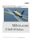
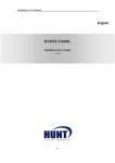
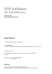
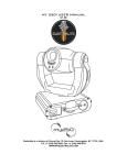
APPLICATION SOFTWARE
USER’S MANUAL
TARGET MODEL : Hicap, MIG, MID, MIS
DVR HARDWARE SPECIFICATION
HICAP SERIES
CLASSIFICATION
HICAP50
HICAP100
HICAP200
160 mm × 110 mm
200 mm × 110 mm
265 mm × 110 mm
6.3 in. × 4.3 in.
7.9 in. × 4.3 in.
10.5 in. × 4.3 in.
4.3 W
7.9 W
13.0 W
PHYSICAL FORM FACTOR
POWER CONSUMPTION
PCI INTERFACE
33 , BUS Master, 132Mbyte/sec, PCI Rev. 2.1 compliant
INPUT NUMBERS
16 ea
16 ea
INPUT VOLTAGE
1V p.p. required
INPUT IMPEDANCE
VIDEO
16 ea
75
FORMATS SUPPORTED
50
NTSC, 60
PAL
1. External two(2) octopus BNC cables (Each cable input : 8ea),
CONNECT TYPE
2. Internal four(4) Molex connectors (Each connector input : 4ea)
OUTPUT NUMBERS
One(1) Switched(full size) Composite Video Out
CIF (DEFAULT)
352 × 240
2CIF
704 × 240
RESOLUTION
4CIF
704 × 480
SUPPORTED
CIF (DEFAULT)
352 × 288
2CIF
704 × 288
4CIF
704 × 576
NTSC
PAL
Max. TOTAL DISPLAY FRAME RATE
60fps
120fps
240fps
Max. TOTAL RECORDING FRAME RATE
50fps
100fps
200fps
Max. RECORDING FPS PER CHANNEL
3fps
6fps
12fps
NUMBER OF DI/O BUILT-IN ON BOARD
16 Sensor Inputs, 4 Alarm Outputs
HARDWARE WATCHDOG
YES
VIDEO MOTION DETECTION
BY SOFTWARE
S/W VIDEO CODEC PROVIDED
Morgan Motion-JPEG, MPEG4 *
M-JPEG
6 ~ 12 Kbyte
MPEG4
2 ~ 4 Kbyte
AVERAGE FILE SIZE
* The compression speed of MPEG4 codec is around 150fps with a Pentium IV 1.6GB CPU. Therefore, MPEG4 does not fully
support Hicap200 DVR board that can capture 200 frames per second.
MID & MIS SERIES
CLASSIFICATION
MID8CH*
MIG4CH
MID16CH
MIS8CH*
MIS16CH
182 mm × 109 mm
184 mm × 109 mm
265 mm × 109 mm
7.1 in. × 4.28 in.
7.24 in. × 4.28 in.
10.43 in. × 4.28 in.
8W
19 W
24 W
PHYSICAL FORM FACTOR
POWER CONSUMPTION
PCI INTERFACE
33 , BUS Master, 132Mbyte/sec, PCI Rev. 2.1 compliant
INPUT NUMBERS
4
8
16
INPUT VOLTAGE
16
1 V p.p.
INPUT IMPEDANCE
VIDEO
8
75
FORMATS SUPPORTED
50
NTSC, 60
PAL
1. External two(2) octopus BNC cables (Each cable input : 8ea),
CONNECT TYPE
BNC connector**
2. Internal four(4) Molex connectors (Each connector input : 4ea)
1 C&S***
Two(2) Composite & Super Video Outputs (optional)****
CIF (DEFAULT)
344×240
352×240
2CIF
688×240
704×240
RESOLUTION
4CIF
688×480
704×480
SUPPORTED
CIF (DEFAULT)
344×288
352×288
2CIF
688×240
704×288
4CIF
688×480
704×576
OUTPUT NUMBERS
NTSC
PAL
Max. TOTAL DISPLAY FRAME RATE
Real-live
*****
Real-live
Real-live
Real-live
Real-live
Max. TOTAL RECORDING FRAME RATE
100fps
25fps
25fps
100fps
100fps
Max. PER CHANNEL RECORDING FPS
25fps
3fps
1fps
12fps
6fps
NUMBER OF DI/O BUILT-IN ON BOARD
16 Sensor Inputs, 4 Alarm Outputs
1
HARDWARE WATCHDOG
YES
VIDEO MOTION DETECTION
SOFTWARE
S/W VIDEO CODEC PROVIDED
Morgan Multimedia MOTION-JPEG, MPEG4
AVERAGE FILE SIZE
M-JPEG
6~10Kbyte
PER CODEC
MPEG4
2~3Kbyte
* The main MID and MIS boards have two daughter boards each. With one daughter board added on, it becomes MID8ch and
MIS8ch. With two daughter boards, it becomes MID16ch and MIS16ch.
MID and MIS share the daughter board. As you can see above, the only difference between MID and MIS is the total recording
speed per second. MIS records videos 100fps per second while it is 25fps with MID.
** MIG4CH is designed for only 4 channels and has 4 BNC connectors. It has one (1) internal Molex connector as well.
*** MIG4CH TV OUT has a composite and super video out in a pair. This displays the same video on analog TV with PC monitor
screen without GUI. The output is not programmable at all but fixed by designing hardware.
**** Each composite and super video out in a pair displays the same video on analog TV. As you know, the quality of super
video out is better than composite’s. The MID & MIS TV out is an optional add-on board that you need to purchase additionally.
TV out 1 displays the same video as the PC monitor screen. However, TV out 2 is dependent on the PC monitor screen to
display videos on analog TV as figured below. The output is not programmable at all but fixed by designing hardware.
Division
PC Monitor
TV Out 1
TV Out 2
1
Ch. 1
Ch. 1
Ch. 5
4
Ch. 1 ~ Ch. 4
Ch. 1 ~ Ch. 4
Ch. 5 ~ Ch. 8
8
Ch. 1 ~ Ch. 8
Ch. 1 ~ Ch. 8
Ch. 9 ~ Ch. 16
16
Ch. 1 ~ Ch. 16
Ch. 1 ~ Ch. 16
Ch. 1 ~ Ch. 16
***** Unlike Hicap series, MIG4CH, MID and MIS have hardware overlay function that provides real-live display. You can
monitor clear videos in real-live while it records videos respectably as described in the specification sheet. Therefore, what you
monitor is different from what you can record.
As the full frames of a single video per second is 30fps, it can be equal to 240fps for 8ch DVR board and 480fps for 16ch one.
2
DVR HARDWARE LAYOUT & DESCRIPTION
HICAP SERIES
1) External octopus BNC cable:
video inputs Ch. No. 1 ~ 8
2) External octopus BNC cable:
video inputs Ch. No. 9 ~ 16
3) Internal Molex connector:
video inputs Ch. No. 1 ~ 4
4) Internal Molex connector:
video inputs Ch. No. 5 ~ 8
5) Internal Molex connector:
video inputs Ch. No. 9 ~ 12
6) Internal Molex connector:
video inputs Ch. No. 13 ~ 16
7) Watch-Dog connector:
DVR board to the reset pin of PC motherboard
8) Reset connector:
From the reset switch of PC case to DVR board
9) DIO connector:
16 digital inputs and 4 digital outputs
10) Composite Video Out:
To display one video in full screen on analog TV
3
MID & MIS SERIES
1) External octopus BNC cable:
video inputs Ch. No. 1 ~ 8
2) External octopus BNC cable:
video inputs Ch. No. 9 ~ 16
3) Internal Molex connector:
video inputs Ch. No. 1 ~ 4
4) Internal Molex connector:
video inputs Ch. No. 5 ~ 8
5) Internal Molex connector:
video inputs Ch. No. 9 ~ 12
6) Internal Molex connector:
video inputs Ch. No. 13 ~ 16
7) Watch-Dog connector:
DVR board to the reset pin of PC motherboard
8) Reset connector:
From the reset switch of PC case to DVR board
9) DIO connector:
16 digital inputs and 4 digital outputs
10) MID/MIS TV-out connector:
To display multiplexed or one Ch. full video on analog TV
4
MIG4CH
1) External BNC connector:
video inputs Ch. No. 1 ~ 4
2) Internal Molex connector:
video inputs Ch. No. 1 ~ 4
3) Watch-Dog connector:
DVR board to the reset pin of PC motherboard
4) Reset connector:
From the reset switch of PC case to DVR board
5) DIO connector:
16 digital inputs and 4 digital outputs
6) MIG4ch TV-out connector:
To display multiplexed or one Ch. full video on analog TV
On the PCB of each board’s rear side, you can find serial number attached. If they are removed, is not
responsible for free warrantee. We guarantee our products for the 15 months since it was shipped to customers.
Each model’s serial number starts as follows;
Hicap50: H5-XXXX-XXXX
Hicap100: H10-XXXX-XXXX
Hicap200: H20-XXXX-XXXX
MID series: D8-XXXX-XXXX
MIS series: M8-XXXX-XXXX
MIG4ch: G4-XXXX-XXXX
5
DIO (Digital Input / Output)
Every DVR board has a DIO connector on the board. It is designed for 16 Sensor Inputs and 4 Alarm Outputs.
Our DVR boards have this DIO circuit drawn as below on PCBs. If you like to design your own DIO guide or panel
and use them with our DVR boards, refer to the pin assigns below.
Back-Panel (PC Assemble Type)
DIO Guide
(16 BNC video Inputs + DIO)
(DIO only)
6
‘DIO Guide’ Connections.
This is an example how to wire connections between Sensors and Alarms with our DIO Guide.
DI connection.
To use DI sensors, you need to configure an adaptor with EXTERNAL VCC+12 and EXTERNAL GND as it is
shown above first. This is required because our DVR boards use photo diodes to receive signals from DI. Using
DI in this way can protect the DVR board from any electronic shock or harmful static electricity.
DO connection.
When you connect DO alarms, you connect with 'B' and 'C'. The DO is opened and it is going to close with
signals from the application.
7
'BNC Back-panel' Layout and Description.
CH1
: Camera Channel 1
CH2
: Camera Channel 2
CH3
: Camera Channel 3
CH4
: Camera Channel 4
CH5
: Camera Channel 5
CH6
: Camera Channel 6
CH7
: Camera Channel 7
CH8
: Camera Channel 8
CH9
: Camera Channel 9
CH10
: Camera Channel10
CH11
: Camera Channel11
CH12
: Camera Channel12
CH13
: Camera Channel13
CH14
: Camera Channel14
CH15
: Camera Channel15
CH16
: Camera Channel16
J1
: Molex 8pin Connector (Camera 1~4)
J2
: Molex 8pin Connector (Camera 5~8)
J3
: Molex 8pin Connector (Camera 9~12)
J4
: Molex 8pin Connector (Camera 13~16)
S1 ~ S16
: Sensor Inputs (16ea)
DO1 ~ DO4
: Alarm Outputs (4ea)
EXT12/EXTG : External Power +12 / External Ground
INT12/INTG
: Internal Power +12 / Internal Ground
8
‘BNC Back-panel’ Connections
9
PC SPECIFICATION REQUIRED
PC MOTHERBOARD
Our DVR boards are compatible with Intel a chipset ATX motherboard. You can use a motherboard built-on Intel
Chipset.
I) A few slim PC and specially OEM motherboards with Intel chipset might not be compatible with our board.
II) We have found that some motherboards with SIS chipset work very well with our board. However, we do not recommend you
to use SIS chipset motherboards because the working condition is different from manufacturers.
III) Some motherboards with VIA chipset provide unstable PCI clock although you can find some good VIA chipset
motherboards per our model. We do not recommend you to use VIA chipset motherboards either.
IV) The motherboard we recommend is only one with Intel chipset. If you still want to try other chipset motherboards, you need
to test and find one at your side.
V) If you have a problem with any motherboard with Intel chipset, please contact us.
CPU
Since we recommend Intel chipset motherboard, we also recommend you to use Intel CPU because Intel does
not support AMD CPU with their chipsets. We recommend Intel Pentium IV 1.6 or faster with our application.
I) It was reported that AMD CPU with some VIA chipset could work with some of our models but we do not recommend.
II) Our drivers are not compatible with dual CPUs. You cannot use dual CPUs with our DVR board.
III) The minimum CPU specification required is Pentium III 800. For Hicap200, we recommend you to use at least Pentium IV
2.4 or faster because it requires a lot of CPU work to get the maximum recording frame.
VGA
We recommend ATI chipset built-on AGP VGA card.
I) Some customers use other chipset VGA card but we found that ATI VGA card is the one without any problem.
II) If you still want to try other chipset VGA card, you need to test and find one at your side.
RAM
Minimum RAM required: 64MB, RAM recommended: 256MB
OPERATING SYSTEM AND OTHER REQUIRED SOFTWARE
Operating System: Windows98, 98SE, ME, 2000 and XP. Required Software: DirectX 8.1a or Higher Version
CD-ROM INSTALLATION ORDER
When you install HDD(Hard Disk Drive)s and CD-ROM, make sure that you need to place CD-ROM drive as the
last one. If this is not placed that way, you are not able to use HDDs after CD-ROM in our application.
10
HERA AUDIO BOARD
HERA LAYOUT AND DESCRIPTION
This installation is required if you have a Hera board to record audios. If you do not have a Hera board, you can
just skip this section.
In our Ver. 5.X.X, we support AC97 audio device or your sound card device to record only one channel. If you like
to record more than 2 audio channels or up to 16 audio channels, you need to use a Hera board.
120*92 (mm)
1) External RCA cable connector
: Audio Inputs (8ch : 1~8)
2) External RCA cable connector
: Audio Inputs (8ch : 9~16)
3) Internal Molex cable connector
: Audio Inputs (4ch : 5~8)
4) Internal Molex cable connector
: Audio Inputs (4ch : 1~4)
5) Internal Molex cable connector
: Audio Inputs (4ch : 13~16)
6) Internal Molex cable connector
: Audio Inputs (4ch : 9~12)
7) Speaker Out
: 1ea
8) Line Out
: 1ea
HERA HARDWARE SPECIFICATION
Audio Inputs
: Full 16ch in realtime
Audio Outputs
: Speaker Out 1ea, Line Out 1ea
Sample Bits
: 12Bit
Sample Rate
: 8, 11, 16, 22 Kbit per channel (Selectable)
Audio Signal Type : Mono
Data Format
: PCM, GSM(by Software)
11
GENERAL INFORMATION ABOUT HERA
In our application Ver. 5.X.X, you have to select one between Hera and AC97 (Motherboard Sound device or any
Sound card device).
When using a Hera board, each Audio channel is recorded together with the same video channel.
For Hera board inputs, we provide two RCA octopus cables and each has 8 channel inputs. Since the connector
type is RCA, you need to convert the connector into RCA if you want to connect a microphone with Hera.
Hera board has OP-AMP to magnify audio inputs. So, if audio data inputs are already magnified, the captured
audio data.
Available usernames and passwords are up to 127 different usernames and passwords.
AUTO SWITCHING
To select Auto Switching Mode, click ‘Enable Auto Switching’ and set the time. It will automatically switch video
monitoring type (one video, 4 videos, and 8 videos) to the very next camera group per selected time. This is the
same function key of Switch button on the main DVR program. This will also switch video outs on analog TV.
MOTION DETECTION BEEP
To select M/D Beep, just click the box. It will automatically make some sound through pc speaker when motion
detection is triggered.
10-1-8. PTZ
If you have pan/tilt devices you want to control, click ‘Enable PTZ’ and choose the right protocol and the port you
want to use among those we support. If you have any Pan/Tilt brand you wish to use, we can implement the
brand into our Application software but need you to send us a sample PTZ and its protocol.
12
-
DISPLAY
Select your video type between ‘PAL’ and ‘NTSC’.
AUDIO DEVICE
You can select one of 2 Audio Devices we support.
If you select ‘Hera Device’, you need to install Hera board on your PC platform.
Using this Hera device, it is possible to record sound data from 16 Audio channels up to Max.44KHz in real time.
It means you can record not only videos but also Audio data providing real high Audio quality. Also, you can select
‘Sound Device’ if you have installed any PC sound card or AC 97 port on the motherboard you have. But this
provides you only 1 channel Audio recording in our application.
REMOTE PORT
You can select Network port number to open for the remote software sites. In case of using a Network protection
software like Firewall, you can set this port as you like to open.
13
NETWORK
Click ‘Enable Network’ if you wish to allow remote client systems to monitor, search recorded images in the main
system and save images in client systems. LAN, ISDN, and PSTN are supported. If the “Enable Network” box is
not checked, no remote client access will be allowed.
If you checked ‘Enable Network’ and “LAN” but you have no Ethernet cards on your system, then it comes up
saying that ‘Address in the specified family cannot be used with this socket’. It does not shut down your system
but just warns you that you have no Ethernet card on it.
If you checked ‘Enable Network’ and “PSTN” but you have no PSTN (Modem) cards on your system, then it
comes up saying that ‘The comport open error’. It does not shut down your system but just warns you that you
have no PSTN modem on it.
14
RECORDING
To set up and use this RECORDING part, the following information is very important.
All DVR boards have a maximum recording speed per video type as follows;
NTSC
PAL
Model
Max. total fps
Max. fps per Ch.
Max. total fps
Max. fps per Ch.
Hicap50
60
3
50
3
Hicap100
120
7
100
6
Hicap200
240
15
200
12
MIG4ch
120
30
100
25
MID8ch
30
3
25
3
MID16ch
30
1
25
1
MIS8ch
120
15
100
12
MIS16ch
120
7
100
6
15
The maximum recording speed is the ideal fps from our DVR board and it may not be the same.
Now, you need to know that there is a video recording chip on each DVR board. Each recording chip can record
videos at max. 30fps in NTSC and 25fps in PAL. So, there are numbers of video recording chip on each DVR
board as follows.
Model
Chip No.
Cameras
TW – 1
Camera no. 1, 3, 5, 7, 9, 11, 13, 15
TW – 2
Camera no. 2, 4, 6, 8, 10, 12, 14, 16
TW – 1
Camera no. 1, 5, 9, 13
TW – 2
Camera no. 2, 6, 10, 14
TW – 3
Camera no. 3, 7, 11, 15
TW – 4
Camera no. 4, 8, 12, 16
TW – 1
Camera no. 1, 9
TW – 2
Camera no. 2, 10
TW – 3
Camera no. 3, 11
TW – 4
Camera no. 4, 12
TW – 5
Camera no. 5, 13
TW – 6
Camera no. 6, 14
TW – 7
Camera no. 7, 15
TW – 8
Camera no. 8, 16
TW – 1
Camera no. 1
TW – 2
Camera no. 2
TW – 3
Camera no. 3
TW – 4
Camera no. 4
MID8ch
TW – 1
Camera no. 1, 2, 3, 4, 5, 6, 7, 8
MID16ch
TW – 1
Camera no. 1, 2, 3, 4, 5, 6, 7, 8, 9, 10, 11, 12, 13, 14, 15
TW – 1
Camera no. 1, 5
TW – 2
Camera no. 2, 6
TW – 3
Camera no. 3, 7
TW – 4
Camera no. 4, 8
TW – 1
Camera no. 1, 5, 9, 13
TW – 2
Camera no. 2, 6, 10, 14
TW – 3
Camera no. 3, 7, 11, 15
TW – 4
Camera no. 4, 8, 12, 16
Hicap50
Hicap100
Hicap200
MIG4ch
MIS8ch
MIS16ch
16
To share the chip, cameras are hooked up differently in each model as you can see.
For example, when you connect only 4 cameras with a Hicap50 to camera 1, 2, 3, and 4, the each recording
frame you can get Max. per channel will be 15fps in NTSC and 12fps in PAL.
However, if you connect to camera 1, 3, 5, and 7, you use only one chip and the maximum frame will be 30fps. So,
the each recording frame you can get Max. per channel will be 7fps in NTSC and 6fps in PAL.
When you slice vide frames per channel, you can set up recording frames differently per channel. In the same
recording chip group, you can slice video frames as you like.
In Hicap100, you can slice 30fps for 4 cameras instead of setting up the recording frame equal to every camera.
You can set Camera 1 at 10fps and provide the left frames for other cameras. In this case, you reduce frame rate
first to provide more frame rate to other channels.
Please, note that MIG4ch is a bit different from other models. Although you set up each recording speed
differently per channel, MIG4ch has a trend to record videos at the highest frame you set for any camera.
CAMERA SELECT
You can choose any camera number by clicking the number. Then, you can individually set options you like per
each camera.
If you click ‘A’, it automatically set ‘Capture Frame’ and ‘Continuous Recording Frame’ to average frame for every
camera channel. After you set all options for any camera channel, it will automatically change what you have
chosen into other camera channels as well except the case ‘Capture Frame’ and ‘Continuous Recording Frame’
are set when you click ‘A’.
If you want to adjust ‘Capture Frame’ and ‘Continuous Recording Frame’ per each camera, you should not click
‘A’ because it will make every camera’s frame to the default rate as average.
DEFAULT
Click ‘Enable Camera’ if you want to use the selected camera. Then, the other options will be enable to be
selected.
If you clicked ‘Camera Position’ on OSD Mode of DEFAULT SETUP page, what you name in the box of
Installation Location will be displayed while monitoring.
17
RECORD
In our Application program, we support three resolutions such as Low(352*240), High(704*240), and
Progressive(704*480).
Regarding High resolution (704*480:NTSC, 704*576:PAL), do not select 704*480 in our application unless you
use a progressive camera. It means that you actually record interlaced videos at this resolution. To record videos
at 704*480 without interlaced videos, you must use Progressive CCTV cameras.
Otherwise, you generally have to select High(704*240) to record videos at 704*480, then it captures videos at a
semi-high resolution like 704*240 and stretch the video out to 704*480 for Playback. Applying this way, it can be
possible to get 704*480 screen in our application.
The video images recorded in 704*240 resolution provide non-interlaced videos than ones recorded in 704*480.
There are some limitations on choosing video resolutions due to computer PCI bandwidth.
Therefore, we recommend you to select video resolutions according to the following;
- Required data size per Video Resolution
Low Video Resolution (352*240) per Recording chip group: 5MB/sec
High Video Resolution (704*240) per Recording chip group: 10MB/sec
Progressive Video Resolution (704*480) per Recording chip group: 20MB/sec
Live Display board requires basically 20MB/sec.
So, you have a limitation to select a video resolution for Recording chip groups with some DVR models.
Hicap50: 2 Recording chips- 10~40MB/sec (No problem with any resolutions mixed)
Hicap100:
4 Recording chips- 20~80MB/sec (Should be lower than 60MB/sec always)
Hicap200:
8 Recording chips- 40~160MB/sec (Should be lower than 60MB/sec always)
MIG4ch:
4 Recording chips- 20~80MB/sec+20MB/sec (Should be lower than 60MB/sec always)
MID series:
1 Recording chip- 5~20MB/sec+20MB/sec (No problem with any resolutions mixed)
MIS series:
4 Recording chip- 20~80MB/sec+20MB/sec (Should be lower than 60MB/sec always)
For Hicap100, Hicap200, MIG4ch and MIS series, you need to take care of the video resolutions per the group to
avoid distorted videos. As many as you mix different resolutions, the maximum recording speed you can get will
be decreasing. So, if you need to record cameras at a different video resolution, it’d be better get same resolution
cameras in the same video group so that you can avoid losing many frames from it.
You can select between 1~99 for Quality. The more you select high quality, the more you can get clear and vivid
images, however it’s file size will be bigger. When codec you’ve chosen is MPEG4, you can’t adjust video quality
as it is fixed.
18
CAPTURE
Capture Frame is the frame rate per second that Hicap series display videos on the Main software in our
application. You can add more frame rate on any channel after you reduce frame rates from other channels in the
same Recording chip group. So, it displays and records videos at Capture Frame rate as it is set.
Continuous Recording Frame is used only when you schedule RECORD SCHEDULE with a Continuous mode
while Sensor, Motion, Audio, and Sensor & Motion recording modes will record videos at Capture Frame rate.
Continuous Recording Frame cannot be higher than Capture Frame so it depends on the Capture Frame rate.
Unlike Hicap series, the display of MIG4ch, MID and MIS series just provide real-live display for monitoring. In
these models, Capture Frame does not have any relationship with their Live display at all but only with recording
modes.
Note that if there is no camera connection; please do not select “Enable Camera”.
If you select enable camera which really have no camera input, it might cause unexpected operation
19
CODEC
You can choose Video Compression Codec we provide between MJPG and MPEG4. If you choose MJPG as your
video codec, you can get high quality images although the file size is bigger than MPEG4’s. Meanwhile, if you
prefer smaller file size to the Video quality, we recommend you to choose MPEG4 as the compressed file size of
MPEG4 is minimum twice or three times smaller than MJPG’s.
You can select video compression codec per each camera differently.
EVENT FRAME
In Sensor, Motion, Audio and Sensor & Motion recording mode, you can record up to 3 frames before and after
the event triggering with Pre & Post Frame.
By using Hold Event, you can record more video frames when events from Sensor, Motion, Audio and Sensor &
Motion modes are triggered.
20
(A)
)
RECORD SCHDULE
You can set up schedules for recording in this mode. Schedule is divided by days and hours. You can select
individual blocks or select all the days and hours by clicking the corner blank (A).
You can select recording modes:
* Stop
Does not record at all. Monitor only.
* Continuous
Continuously records images
* Sensor
Record images when DI sensor signals
* Motion
Record images when motion is detected
* Audio
Record images when Audio is detected
* Sensor & Motion
Record images when DI sensor signals or when motion is detected
When you select Sensor, Motion, Audio or Sensor & Motion for recording videos, It is very important that you also
need to go to DI/DO, Motion and Audio sections for setting up conditions to record videos.
21
DI/DO
If you have installed our DIO guide or BNC back panel, you can use sensor input and alarm output functions. To
use this mode, you have to have already selected the same video channel with Sensor recording mode in
Recording setup.
DI SELECT: Select any of 16 Sensor Inputs.
SENSOR
Must click ‘Sensor Application’ to use this sensor.
Sensor Name
: You can name this selected DI kinds.
Sensor Type
: Choose sensor type between these below.
0 : Low-active(1 0)
1 : High-active(0 1)
DO SELECT : Click DO numbers you want to hook up with the selected DI
Sensor Location
: You can name where the DI is installed.
Camera Number
: Select cameras that you want to record videos with the selected sensor triggered.
DO setting time
: Select how long you want to give signals to DO sensors.
22
MOTION
CAMERA SELECT
Select a camera to trigger Motion Detection.
SENSITIVITY
You can adjust the sensitivity on detecting Motions. As closed to 1, the sensitivity level goes more sensitive.
DO SELECT
If you installed DIO board or Back panel, you can use DO to assign Alarms to trigger with Motion Detected.
Click DO numbers you want to connect with the selected camera. Then, select how long you want to assign for
DOs you select.
NIGHT MOTION
During night times, it depends on camera quality but they usually take a lot of video noises. So, although you set
up a right value for day times for Motion Detection, this video channel may keep recording videos all night long. To
avoid this problem, you click Enable Night Motion. Then, you can set times and different value for night times.
23
INSERT MOTION DETECTION ZONE
You can select each individual camera one by one and insert motion detection zones (up to 16 zones) by clicking
on the “Insert Zone” box and drawing in boxed zones. Then, click “Test”. It will display motion signs as above if
there is any motion detected. By clicking “Insert Entire Zone”, you will select the whole box automatically.
Insert Entire Zone
You can select when you wish to set whole area as motion detection zone.
However, as the motion detection zone is smaller, it is much more sensitive than when it’s not set as motion
detection zone at the same condition of sensitivity.
Clear Zone
You can remove motion detection zone you created one by one by clicking left mouse button.
Clear Entire Zone
You can remove whole area you created by setting Insert Entire Zone
The sensitivity of Motion Detection in our application is from the percentage of changed pixels in selected Zone.
This is very important to understand this concept clearly so that you use our application well without any problem
with your customer.
When you insert a small zone in the box, let’s say there are 500 pixels and you set the sensitivity level as 1 for
example. In this case, our application will detect Motions when at least over 5 pixels are different from the very
previous video frame.
At the same video camera above, you insert a smaller zone this time and let’s say there are 100 pixels at the
same sensitivity level condition. In this case, our application will detect Motions with at least over 1 pixel is
different from the very previous video frame.
As it describes above, a smaller MD zone is more sensitive than big one at the same sensitivity condition. If there
is more than 1 MD zone in the box, our application set the condition with the smallest MD zone for the percentage
concept.
If it monitors kind of a long range, objects are probably smaller than one in real. In this case, although you set the
sensitivity level as 1 with an entire zone selected, it will not detect video motion detections at all. So, you’d better
break some more zones instead of one although CPU becomes a bit more busy.
24
AUDIO
AUDIO SELECT
If you have install Hera or AC97 and select AUIDO channels here, you will be able to record audios with videos.
Like Recording and DI/DO, if you have set Audio Recording mode with Audio Detection, you must select the
same audio channel with video here and set the options as you like.
DO SELECT
If you installed DIO board or Back panel, you can use DO to assign Alarms to trigger with Audio Detected.
Click DO numbers you want to connect with the selected camera. Then, select how long you want to assign for
DOs you select.
AUDIO
If you use a Hera board, you can select all audio channels but you will be able to select only one with AC97.
The data from each audio channel will be together with the same channel video. Click “Enable Audio” to use and
set “Recording Time” to record audio data for the seconds you set up with Audio Detection.
25
SAMPLING RATE
‘Sampling Rate’ is referred to the Audio sound level to record. The higher you select the rate, the clearer the
recorded sound you’ll get. In the mean time, the size of recorded Audio file will be bigger when you select a higher
bit rate.
AUDIO DETECTION
If you want to record Audio data by using this Audio Detection function, you need to adjust the height of two red
lines for the sensitivity of Audio detection. Audio data between two red lines will be ignored. The data out of two
red lines as you can see above will be detected and recorded in our application. Once it is detected, you will see
signs like left.
The default setting of this Audio Detection window is referred to 0. There is no gap between two red lines. In this
case, our program could detect Audio data although there is no Audio input with some noisy. Then, the system
will recognize it as Audio detected.
26
COLOR
COLOR CONTROL
You can adjust Brightness, Contrast, Sharpness, Hue, Saturation U, and Saturation V independently for each
camera as you like.
Saturation U is referred to control brightness of blue color and Saturation V is referred to control brightness of red
color.
CAMERA SELECT
Select camera number that you want to adjust the color setting.
27
AUTO BACKUP
You can backup automatically as you set the day and time in this setting.
TARGET DRIVE
You can select physical drive to backup recorded videos and it’s possible to select a multitude of drives. However,
our application program does not support CD-RW directly for now.
TIME
It will automatically backup at selected time to the target drive as you set.
If there is 10GB data recorded and you have 5GB HDD on E drive for the condition of picture above, 6 o’clock
28
FILE MANAGEMENT
The file management function allows you to efficiently use your hard drive space. It displays the size and location
of hard drives in use and free space remaining. The size of one image-box is about 100M bytes. You need to
setup image-boxes that the application program uses to store images. The application program only saves
images in the image-boxes you create. When all the image-boxes are full, the program deletes the one the oldest
video of the image-box and can write new images. Therefore, if you want to save old image data longer, you need
to add more image-boxes on your hard drive.
Present Image-box
: shows you how many image-boxes you have made.
Remain Image-box
: shows you how many more image-boxes you have available.
Add Image-box
: shows the number of image-boxes you can add.
To add more image-boxes, click the box that is below ‘Add Imagebox’. Scroll down and select the number of
image-boxes you wish to make. Then, you must click ‘Start’ button.
When you install hard drives with a CD-ROM drive, the CD-ROM drive should be installed as the last drive. If you
install a CD-ROM drive before any hard drives, our application can not really check HDDs after CD-ROM.
29
We are using a special data recording system using Imagebox.
In this system, until you fill one image-box up with video data, you are not able to playback the videos in the
current imagebox you are using to record videos.
If you have must-see videos in the current imagebox, you need to exit the main application first and run the
Search program only. Then, you can playback videos in any imagebox.
MAIN PROGRAM
When you are done setting in the setup screen, click ‘EXIT’ button. The screen will change to the main application
program as above.
Changing Mode Button
Click to go to the ‘Setup’ screen
30
Click to go to the ‘Search’ screen
Click to go to the ‘Backup’ screen
Manual Recording Button
Click this button to begin recording currently monitored video images
- PTZ Control Button
To use this function, you must click ‘Enable PTZ’ in the Setup program and select a protocol you like to use.
Note that some buttons may not work per protocol model because every protocol does not have all the
functions listed on PTZ Control Button below.
Double click to go to PTZ control mode as you see this right
screen.
Pan/Tilt Camera Number: You can select number installed pan/tilt camera device.
Auto Pan: The Pan device will move automatically
Camera light: Enables night lighted flash function for PTZ camera with night flash function.
31
Near/far: Pan/Tilt focus controls for near/far videos
Zoom In/Out: Zoom In/Out controls
Power
and Direction Keys: Controls Pan/Tilt movement
32
1
2
3
4
5
6
7
8
9
Screen Display Button
MIS and MID DVR Boards provide you various monitoring screens as above. Unlike MIS and MID, Hicap series
provide 1, 4, 9 and 16 screens only.
If you double click the display screen, it will change in a full screen mode.
When you select unbalanced screens such as no. 3, 4, 6, 7, and 8, if you click right mouse button on any small
sized cameras, the camera will be changed into the big screen.
Auto Switching Button
Click this button to switch automatically, it will automatically switch video monitoring type one video,4
videos, 8 videos as you click the screen display button.
When you click this button above to use this function, you will see this button changed red. If you want
to stop this function, just click this button again.
Indicates your current capacity of hard disk you’re using.
Displays day, time and program status
Indicates images being recorded in ‘Always’ mode while monitoring
Indicates images being recorded in ‘Motion’ mode while monitoring
Indicates images being recorded in ‘Sensor’ mode while monitoring
Indicates images being recorded in ‘Manual’ mode while monitoring
Indicates images being recorded in ‘Audio’ mode while monitoring
33
Audio Input Button: Click
to get Audio input.
To use this real-live Audio out function, you should enable Audio Channel
you
want to control from Setup Program.
This screen will fill the window up
if there is no camera signal.
- Exit Button: Click to exit. The below screen will follow up.
You will see the screen as below, when you click the ‘EXIT’ button on our main program, if you checked
‘Activate Password Request’.
User name and password should be in accordance with you set at ‘LOG IN’
34
*Easy Output function
If you click right mouse button, you’ll see red, green and blue outlines of the picture. This presents you TV Out,
Audio Out, TV Out & Audio Out function.
Red outline: Red outline shows you this channel is engaged to TV out. Double
click right mouse button to change channel. This is only for Hicap series that
have a composite video out in full screen.
Green outline: Green outline shows you this channel is engaged to Audio out.
You’ll hear real-live Audio sound by Audio out function. Click right mouse
button to change channel. This is for all DVR models.
Blue outline: Blue outline shows you this channel is engaged to TV out and
Audio out both at the same time. Since MIG4ch, MID and MIS series do not
provide a Hicap video out, this blue screen will not be shown in these models.
Double click left mouse button on screen, will change videos in full video screen.
35
SEARCH PROGRAM
You can search recorded images by Date. If image data is saved on your hard drive, it will be indicated on the
calendar with blue-purple color.
Clicking on a date in blue-purple will bring up Imageboxes for the date.
When you have imageboxes for a date, click an imagebox you want to playback. Then, you can see recorded
cameras in green color at the bottom of Window.
36
The sign, o/x, of Audio data shows whether Audio is recorded or not. Above data shows
that Audio channel1 was recorded but else were not.
37
The hour blocks for each camera at the bottom will indicate if images were recorded, which camera(s) recorded
images and the hour(s) images were recorded.
After selecting an hour block of recorded images, you can determine the exact time of the recording in the time
scale directly below.
When it starts to playback videos, it starts from the beginning of the time you select.
If you want to playback any specific minute or second, click ‘Pause’ first and select a time you like to playback in
pink color.
Then, when you click ‘Pause’ key again, it will display the right time you picked. With a vertical side bar, you can
select among the 16 cameras to playback if those have some recorded images.
38
When you wish to playback more than one camera channels, you need to set video playback size to 1X first.
Then, select screen division.
When you playback videos, the following information will be provided on the right side of GUI.
Shows you current time and date.
Shows you recorded time, date and recording status of playback data
Indicates recorded images were recorded in ‘Audio’ mode
Indicates recorded images were recorded in ‘Motion’ mode
39
Indicates recorded images were recorded in ‘Sensor’ mode
Indicates recorded images were recorded in ‘Always’ mode
Indicates recorded images were recorded ‘Manually’
Resets recorded image to default
Sharpens recorded video image
Softens recorded video image
Adjust contrast
Adjust Brightness
Enlarge a video image up to four times(200*200)
1 X default display size
Enlarge display size. Note: works only in single display mode
Go back to previous mode
Saving button. Note: you must pause playback before you click this button.
Shows previous or the next frame
Rewind the video data to the beginning or the end
Play and reverse play button. You can use reverse play button only when it’s one full screen mode.
40
Note that in case you want to hear recorded Audio data, the split screen mode should be one screen mode and
Play Speed should be set on 0. Also, you cannot apply it when you’re using Reverse Playback.
One-video display
Four-videos display
Nine-videos display
Sixteen-videos display
Indicates that you want to playback videos with audios
Indicates that you want to playback videos only
Indicates that you want to playback audios only
Print the video image, Note: you must pause playback.
Watermark: Watermark function prevents you from being cheated on fabricated image data. In
order to use this function, you need to pause a frame during playback. Then, click the Watermark button. And
when you apply this function, the image you apply will be turned out to prove it’s the original. At first, you will
see the Watermark on the left of upside which means you have applied this function. If someone has fabricated
the image you applied, fabricated zones will be changed into white color so that you can distinguish it’s been
fabricated. To use these functions shown above, you need to click ‘Pause’ button first.
Adjust the Play Speed
Exit
41
When you want to save a still video image in BMP format to other drives, you need to click ‘Pause’ button first
during playback and then click ‘Saving Button’.
Then, it will show a window as shown above. It creates an automatic file name with the date and the recorded
time.
According to the same method, you can print a video as well.
Our Application is designed to keep recording although you are in this search mode. However, when you go to
Setup and Backup mode, the main DVR Application will not be working.
42
BACKUP PROGRAM
To backup recorded video data, we only support physical hard drives (No CD-RW supported yet). Our backup
program will copy imageboxes selected to target Drive after creating a directory ‘back’. Without this backup
program, you can just copy imagebox files to other drives. However, our backup viewer program looks for ‘back’
directory only.
BACKUP
When you want to backup only some imageboxes you like to backup, you can use this Backup. Search the
imagebox directory on the left tree structure first. Then, select an imagebox or more that you like to backup.
ALL BACKUP
This will automatically sort all imageboxes you have in your DVR system and try to backup videos to the target
drive you select.
BACKUP VIEW
To playback backup data, you can click this button.
43
Select the target drive and click ‘Backup’. Then, it starts to copy selected image-boxes to the destination drive.
If you just want to backup all video data, simply click ‘All Backup’ button instead of browsing drives. It will
automatically search your drives and let you know the total source size to backup.
44
REMOTE PROGRAM MODE
Our remote program includes some functions such as monitoring videos and control PTZ cameras from a remote
site(s), saving monitored videos and playback in a remote site(s), and searching recorded videos in the main DVR.
Besides, we provide you 2 types of remote program. If you need to monitor videos from just 1 server, you can use
normal Client program. But when you need to monitor videos from multiple servers actually up to 16 server sites,
you can make the most of our Multi-client program.
Before you install our Remote program, check if you have clicked ‘Enable Network’ in the Setup mode of your
main DVR system and selected the right Network type.
Then, check there is a server sign on the bottom of your main screen when you press a windows key of your
keyboard. Once you install our Main Application, our Server program will be installed in your pc automatically, so
you don’t need to install Server program additionally. You just need to check ‘Enable Network’ and select the right
Network type.
45
If you can see the server sign
while your main DVR program is running, it means that the main DVR program
is ready to send videos and our server program is activated.
There is a Client program on the CD we provide.
In the client software directory, You can simply install our Cliet program on your client system. Click ‘Setup’ file to
install.
After installing, you will find this shortcut icon on your windows screen.
Then, double-click the icon and you will see this window on the next page.
46
Click to go to ‘Setup’ mode. Then, you will see this screens below as you select a connection type
between LAN, ISDN, and PSTN.
l
LAN users,
[1] Click ‘LAN’, and then type Remote Port number of main DVR.
[2] Type IP Address of DVR server. Note: it should be a fixed IP Address.
[3] You need to type the ID and Password being used in the main DVR.
[4] Click ‘Setup’
47
l
ISDN or
PSTN users,
[1] Click ‘ISDN’ or ‘PSTN’
[2] Choose modem options of PSTN or ISDN and telephone number
[3] You need to type the ID and Password being used in the main DVR.
[4] Click ‘Setup’
Every country has different ISDN systems. Since Korea do not have ISDN services and could not test ISDN
connections, we have just followed our PSTN format to support ISDN.
Customers have reported that our Client program works for some PSTN brands only. You now how to monitor
videos remotely under LAN but it does not work for you under PSTN. Then, try to change a PSTN modem into a
different version or try to change Communication speed lower.
Note
: If both atz or at&f0 are not acceptable as an Initialize Command, find a proper one from the manual of
your modem and type it there.
48
-LAN user connection.
Click to go to ‘Setup’ mode. Then, you will see this screen below.
Remote Port
: Internal port number of server which installed DVR Board to network.
IP Address
: Type server’s static IP Address.
ID Name : Type the ID being used in the main DVR.
Password: Type the Password being used in the main DVR.
Then, click ‘CONNECT’ button to access server as below screen.
49
Once you setup before then, click ‘REPORT’ button and you will see this screen as similar as above. It has a
data value you connected before.
Double click any IP address you wish to connect and click
50
‘Connect’ once.
If the connection is okay and successful, you can see ‘connect’ icon in color. If it is not connected, ‘Disconnect’
icon will be in color.
-PSTN user connection.
First of all, you need to check Enable Network in the Default Setup page and click PSTN as Communication
Select. Then, click to go to ‘Setup’ mode of remote program. And you’ll see this screen below.
Com Port
: Select port of the modem you’re using.
Communication Speed
: Select Speed of the modem you’re using.
Initialize Command
: Type the Initialize Command of the modem you’re using.
Connect Number
: Type the telephone number you want to connect.
ID Name
: Type the ID being used in the main DVR.
Password
: Type the Password being used in the main DVR.
Note: If both atz or at&f0 are not acceptable as an Initialize Command, find a proper one from the manual of
your modem and type it there.
Then, click ‘Connect’ button to access server.
51
If the connection is okay and successful, you can see ‘Connect’ icon in color as above. And if it is not
connected, ‘Disconnect’ icon will be in color.
52
Once you setup before then, click ‘Report’ button and you will see this screen as similar as above. It has a data
value you connected before.
Double click any address you wish to connect and click
Then you’ll see the screen as above.
From this status, you need to click what you want to do now.
53
‘Connect’ once.
MONITORING VIDEOS AND CONTROL PTZ CAMERAS FROM A REMOTE SITE(S)
To use this function, click
button. Then, you can monitor videos remotely. You can select a screen division
as you wish to monitor.
If you have installed a PTZ camera with your main DVR system, you can also control the PTZ camera remotely.
Click to go to PTZ control mode as you see this right screen
You should open PTZ control mode in the Main same as right screen to control the PTZ camera.
54
SAVING MONITORED VIDEOS AND PLAYBACK IN A REMOTE SITE(S)
You can save the monitored videos in your client PC as well. Click
button during monitoring.
Then, you need to select camera numbers you want to record by clicking this
number.
To playback this saved data in your client PC, click
button next to Setup button.
55
button on each camera
Waiting Time-This function is referred to the speed of playback. Point1 is
settled to 16 mili-second as default in this mode. The number of this point shows you waiting time. If you set this
point to 2,it’ll wait 32 mili-second till the next frame is seen. Accordingly, when you adjust this point lower(to the
left), the playback speed of data will be quicker.
56
SEARCHING RECORDED VIDEOS IN THE MAIN DVR.
To search image-boxes for recorded video data in the main DVR, click
button.
Then, it will display the image box information of the main DVR system. Select an image-box you want to
playback.
Skip Frame Function - You can apply this function only when you’re using quick play.
The displayed box shows you the number of frame per second you want to skip.
You can manage the number of skip frames as you like.
Therefore, the higher you set this point, the quicker the image data will be seen.
57
MULTI-CLIENT PROGRAM
You can also use Multi-client program that allows you to monitor, record and search
videos connected to up to
Max.16 servers simultaneously.
Click Setup button first.
-LAN user connection,
Remote Port: Internal port number of server
which installed DVR Board to network.
IP Address: Type server’s static IP Address.
ID Name: Type the ID being used in the main DVR.
Password: Type the Password being used in the main DVR.
Then, click ‘CONNECT’ button to access server.
58
ISDN or PSTN user connection,
[1] Click ‘ISDN’ or ‘PSTN’
[2] Choose modem options of PSTN or ISDN
and telephone number
[3] You need to type the ID and Password
being used in the main DVR.
[4] Click ‘Setup’
Note: If atz or at&f0 is both not acceptable as an Initialize Command, find a proper one from the manual of your
modem and type it there.
Then, click ‘Report’, and when you click the IP address with left mouse button, you’ll see the screen below. It’s not
necessary to click Connect button in this Multi-client program.
Window01 shows the channel number you set. In other words, if you set the video of a server as Window01, you’ll
see the video of that server as the first video channel among you set. And you can make windows of up to 16
different servers.
Then, you can select the camera input of up to 16 servers’ video data as you like.
59
The date, current time, camera number and IP address are shown on each window.
And you can add camera channels using same way like the picture above.
Then you’ll monitor, record and search videos transferred from multiple sites
at the same time.
60