1
HEAT FLOW METER SVTU-10М
Modifications M1 & M2
Operating manual
SMP.407251.003 OM
(part 1)
March 2010
Documentation:
1 Operating manual SMP.407251.003 OM part 1.
2 Operating manual SMP.407251.003 OM1 part 2.
“Built-in MDM/REG unit – modem connection and regulation unit of heat-flow meter
SVTU-10M (M1, M2)”
Content
1
Preface ..................................................................................................................... 6
2
Assignment .............................................................................................................. 6
3
Technical specifications ........................................................................................... 7
4
Package contents .................................................................................................... 14
5
Structure and functioning of meters........................................................................ 17
6
Marking and sealing ............................................................................................... 23
7
Packing and marking .............................................................................................. 24
8
Safety precautions .................................................................................................. 24
9
Installation ............................................................................................................. 26
10 Setting-up procedures............................................................................................. 39
11 The operating procedure ......................................................................................... 41
12 Servicing ................................................................................................................ 49
13 Typical faultinesses and methods of their elimination ............................................ 50
14 Storing ................................................................................................................... 53
15 Transportation ........................................................................................................ 54
16 Guarantee of manufacturer ..................................................................................... 54
Appendix А Order information ..................................................................................... 58
Appendix B Basic circuits of meter mounting for different configurations..................... 59
Appendix C Connection to additional device examples.................................................. 64
Appendix D Overall and connecting dimensions of calculator ....................................... 67
Appendix E Meter control menu .................................................................................... 68
Appendix F Scheme of device cable .............................................................................. 83
Appendix G Sensors pinout ............................................................................................ 91
Appendix H The scheme of pressure sensor mounting ................................................... 92
Appendix H The scheme of pressure sensor mounting ................................................... 92
Appendix I Overall and setting-out dimensions of flow meter sections (FS) .................. 93
Appendix J How to set hydraulic zero ............................................................................ 97
Abbreviation list
OM – operating manual.
FS – flow meter section with ultrasonic flow sensors FlS.
RТD – resistive temperature detector.
RTD–S – platinum resistive temperature detector manufactured by SEMPAL Co.
NSC RТD – nominal static characteristic of RТD.
FlS – flow sensor.
TS – temperature sensor.
PT – pressure transducer.
3
DN – nominal diameter.
РN – nominal overpressure.
PC – personal computer.
RDU – data reader.
Х – digit on the device display.
MDM/REG – built-in unit for modem connection and regulation
4
Information for customers
Heat- flow meters SVTU-10М (hereinafter referred to as meters) are complex measuring devices, which should undergo the starting-up and adjustment works by qualified personnel at commissioning.
Manufacturer's guarantees (48 months since shipment) extend on the meters which
were put into operation by the specialized enterprises having corresponding credentials from
company-manufacturer. More detailed information is resulted in section 16 ‘Manufacturer’s
Guarantee’.
A recalibration interval is 4 years.
The Quality System SEMPAL is certificated under ISO 9001:2000.
If you have any questions about purchase, maintenance, operation and service of meters, contact us or our authorized regional representatives.
“SEMPAL Co LТD” contacts:
3 Kulibina Street, Kyiv, 03062 Ukraine
Phone/fax: (+38044) 239-2197, (+38044) 239-21-98.
5
1
Preface
The present operating manual (hereinafter referred to as OM) contains information
about assignment, field of application, performance capability and completeness, a principle
of operating and a design, the order of installation and commissioning, the order of operating
and maintenance service of meters.
While meters are in exploitation, it is necessary to be strictly guided by present OM.
Because of the regular work aimed at functional enhancement, improvement of performance capability and increase of meter reliability, manufacturing company SEMPAL Co
LTD reserves the right to itself to change a design of the meter without claiming it in present
OM.
2
Assignment
Heat-flow meters SVTU-10М are intended for:
measurements of the produced or consumed heat energy, volume of the heat-carrier,
temperature of the heat-carrier in supply and return pipelines, overpressure of the
heat-carrier or water, work time (power on time and correct work) or non-work time
(power off time), and also calculations of a mass (mass flow rate) of the heat-carrier
for configurations 2, 4-9 (see the appendix B);
measurements of cold or hot water volumes, water temperature, work time or nonwork time, and also calculation of the mass (mass flow) of water for configurations
1, 3 (see the appendix B);
indication (depending on configuration) of the mentioned measured and calculated
physical quantities and also heat power, the volumetric flow rate of the heat-carrier
or water, overpressure of the heat-carrier or water, current time and date on the indicating device;
forming of the potential output signals on two independent analog outputs (if there
is a built-in MDM/REG unit) in proportion to informative parameters (temperature,
pressure, volumetric flow and heat power) measured by the meter. Application of
the built-in MDM/REG unit in more detail is specified in item 5.11 and in special
manual instruction.
Meters of 7th, 9th configurations also measure temperature of cold water on a source of
heat supply (further under the text - cold water temperature).
Meters of 9th configuration also measure volume of water (water leak), used for refill of
lost heat-carrier on a source of a heat supply (further under the text - feed water volume).
Meters of 4th, 5th, 7th configurations also indicate the calculated difference of heatcarrier volumetric flows in supply and return pipelines (further under the text - water leak).
2.1 Meters depending on their configuration can be applied for the control of heat energy (in the closed-type or open-type systems of a heat supply) or water volume according to
acting rules of the control of heat or water supply and consumption on industrial objects and
objects of a municipal services.
Meters of 9th configuration meant for measurement of produced heat energy on a source
of heat energy.
2.2 Meters depending on their permissible error limits while measuring heat, volume, volume flow rate and mass of the heat-carrier can be represented in following modifications: М1 and М2.
6
2.3
Meters with two-chord FS have only M1 modification.
2.4 The meters can work under the following conditions:
atmospheric pressure can vary from 84.0 up to 106.7 kPa;
relative air humidity is up to 95 %;
power supply can vary from 187 up to 242 V, (50 ± 1, 60 ± 1) Hz or DC;
or power supply is (36 ± 5.4) V, (50 ± 1, 60 ± 1) Hz or DC;
or power supply is (24 ± 3.6) V, (50 ± 1, 60 ± 1) Hz or DC.
3
Technical specifications
3.1 The meter consists of the following functional units:
flow meter section with ultrasonic flow sensors (FS);
resistive temperature detectors (RТD);
SVTU-10М calculator.
Distinctive functional features of meter configurations and basic functional units are
represented in table 3.1. (meter configurations in detail are given in the appendix B)
Таble 3.1
Distinctive structural and functional features
1 Number of FS
2 Number of RТD
3 Measuring the temperature of the heatcarrier in the return pipeline
4 Measuring the temperature of cold water
5 Measuring the temperature in hot water supply system
6 Measuring the volume of the heatcarrier in the supply pipeline
7 Measuring the volume of the heatcarrier in the return pipeline
8 Measuring the volume of water in the
water supply system
9 Measuring the heat energy
10 Indicating heat-carrier (water) leak
11 Measuring the volume of water in the
feeding pipe
Configuration
2/1 2/2 3 4 5 6
1 1 2 2 2 2
2 1 2 2 2 3
1
1
1
2
1
2
7
2
3
8
2
4
9
2
4
−
+
+
−
−
+
+
+
+
+
+
−
−
−
−
−
−
−
+
+
−
+
−
−
−
−
−
−
−
−
−
−
−
+
+
−
+
+
+
+
+
+
+
+
−
−
+
−
−
+
+
−
+
−
−
+
−
−
−
+
−
−
+
−
−
−
−
−
+
−
+
−
+
−
−
−
+
+
+
+
+
−
+
+
+
−
+
−
−
−
−
−
−
−
−
−
−
−
+
Additionally the meter can include one or two overpressure transducers (further under
the text - pressure transducers or PT), which are used for transformation of the heat-carrier
or water overpressure in a range from 0 up to 2.0 MPa (from 0 up to 20 kgf/cm2) in a proportional electric signal with current from 4 up to 20 mA.
Metrological performance of pressure transducers PT is provided according to the individual order.
Meters can include up to six RТD (fifth and sixth temperature measuring channels are
supplied in accordance with the individual order if they have been certified). In that case additional RTD can be used for the control of outdoor temperature.
7
3.2 Meters indicate the results of measurements in CGS (GCal/h, GCal, kgf/сm2)
unit system or SI (MW, GJ, MPa). At shipment indication of measurement information is set
in CGS system.
For the further under the text units of CGS system are used.
3.3 The calculator indicates the following quantities:
heat energy, GJ (GCal);
heat power, МW (GCal/hour);
volume (mass) of the heat-carrier or water, m3 (ton);
volumetric (mass) flow of the heat-carrier or water, m3/hour (ton/hour);
heat-carrier temperature in supply pipeline, С;
heat-carrier temperature in return pipeline, С;
overpressure of the heat-carrier or water, МPа (kgf/cm2);
work time and non-work time, hour;
current time (hours, minutes, seconds) and date.
3.4 The calculator provides storage and output by standard interface RS-232C such
archive data as measured values of heat energy and volume (mass) of the heat-carrier (water), work time and non-work time and also average measured values of temperature:
per hour - during 70 preceding days (hourly archive);
per day - within 1 preceding year (daily archive).
3.5 The number of display digits:
For heat energy, volume (mass) of the heat-carrier or water is 8;
For heat power, volumetric (mass) flow rate of the heat-carrier or water is 5;
For heat-carrier temperature in supply and return pipelines, cold water temperature
is 5;
For overpressure of the heat-carrier or water is 3;
For work time and non-work time, current time is 7;
For date is 8.
3.6 The minimum bit value of digital display at indication of:
heat energy - from 10-7 up to 1 GCal (from 10-7 up to 1 GJ);
volume (mass) of the heat-carrier or water – from 10-7 up to 1 m3 (from 10-7 up to
1 ton);
volumetric (mass) flow rate of the heat-carrier or water – from 0.001 up to
0.1 m3/hour (from 0.001 up to 0.1 ton/hour);
heat power - from 0.001 up to 0.1 GCal/hour (from 0.001 up to 0.1 МW);
heat-carrier temperature in supply and return pipelines, cold water temperature and
water temperature in hot water supply system - 0.01 °C;
overpressure of the heat-carrier or water – 0.1 kgf/сm2 (0.01 МPа);
work time and non-work time – from 10-5 up to 1 hour;
current time – 1 second.
3.7
3.2.
Table 3.2
8
All performance specifications for SVTU – 10M meters are resulted in the table
Flow measurement
section FS
FS-32
FS-50
FS-65
FS-80
FS-100
FS-125
FS-150
FS-200
FS-250
FS-300
FS-350
FS-400
FS-500
FS-600
FS-700
FS-800
FS-900
FS-1000
Measurement range of the heat-carrier (water) volume
flow, m3/hour
Minimal
Transitional
Maximum
(Qmin)
(Qt)
(Qmax)
0.22
0.6
22
0.7
1.4
70
1.2
2.4
120
1.8
3.6
180
2.8
5.7
280
4.5
8.8
450
6.5
12.7
650
11.5
23
1150
18
35
1800
26
51
2600
35
69
3500
45
90
4500
71
141
7100
102
204
10200
140
277
14000
180
362
18000
230
458
23000
285
565
28500
Range of the heat
power, GCal/hour
from 0.00055 to 3.5
from 0.0018 to 11
from 0.003 to 19
from 0.0045 to 28
from 0.007 to 43
from 0.011 to 68
from 0.016 to 100
from 0.028 to 175
from 0.045 to 272
from 0.065 to 393
from 0.087 to 530
from 0.11 to 680
from 0.17 to 1610
from 0.25 to 1540
from 0.35 to 2115
from 0.45 to 2720
from 0.575 to 3475
from 0.71 to 4275
3.8 The temperature of the heat-carrier in supply and return pipelines can vary in a
range from 0 up to 150 С.
3.9 Meters provide heat energy measurement at temperature difference in supply and
return pipelines (∆Т) from 0 up to 150 С. If temperature difference varies from 2.5 up to
150С the error of heat measurement is standardized.
3.10 The maximal pressure measured by the meter is 20 kgf/сm2.
The range of the electric signals proportional to measured pressure should vary from 4
up to 20 mA.
3.11 Meters have standard interface RS-232C, which provides direct connection to the
modem, PC and other peripheral devices (see Appendix C).
3.12 Meters can be equipped with two analog electrical outputs of direct current voltage from 0 up to 10 V or two analog outputs of direct current from 0 up to 20 mA proportional to one of the following quantities:
heat-carrier temperature in supply (return) pipeline, water temperature, cold water
temperature;
overpressure of the heat-carrier (water);
volumetric flow rate of the heat-carrier (water).
The notice. It is possible to configure analog electric signals proportionally to other
measured parameters.
3.13 The nominal supply voltage of meters can be 220 V, or 36 V, or 24 V of direct
current or alternate current with nominal frequency of 50 Hz or 60 Hz.
9
Power, consumed by meters, does not exceed 7 VA.
3.14 Nominal diameters (DN), overall dimensions and the mass of flow measuring
section (FS) and also length and mass of RТD depending on their type are indicated in tables
3.5, 3.6, and in the picture 3.1, 9.7.
The notice:
1 It is possible to increase the total length of FS due to the length of straight sections before and after places for ultrasonic flow sensors installation.
2 DN is the designation of internal diameter, which numerical value is approximately equal to internal diameter of attached pipe sections.
3.15 Meters of 2nd, 5th, 6th, 8th, 9th configurations of M1 modification meet to a grade
of accuracy 2, meters of modification M2 meet to a grade of accuracy 2.5 and meters of 4th,
7th, 9th configurations meet to a grade of accuracy 4.
3.16 Limits of heat energy measurement error for meters of modification М1 for 2nd,
5th, 6th, 8th configurations:
± 1.5 % (± 4.5 %) ─ while ∆T varies from 20 С (included) up to 150 С (included);
± 2 % (± 5.5 %) ─ while ∆T varies from 10 С (included) up to 20 С;
± 5 % (± 7.5 %) ─ while ∆T varies from 2.5 С (included) up to 10 С (included).
Limits of heat energy measurement error while heat-carrier flow rate varies from Qmin
(included) up to Qt are shown in the brackets.
3.17 Limits of relative error of heat energy measurement by meters of modification М1
for 2 , 5th, 6th, 8th configurations:
± 5 % (± 7.5 %) ─ while ∆T varies from 2.5 С (included) up to 10 С;
± 2 % (± 5.5 %) ─ while ∆T varies from 10 С (included) up to 20 С;
± 1.5 % (± 4.5 %) ─ while ∆T varies from 20 С (included) up to 150 С (included).
nd
3.18 Limits of relative error of heat energy measurement by meters of modification
М1 for 4th, 7th, 9th configurations:
± 5 % (± 7 %) ─ while ∆T varies from 2.5 С (included) up to 10 С;
± 2 % (± 5 %) ─ while ∆T varies from 10 С (included) up to 150 С (included).
3.19 Limits of relative error of heat energy measurement by meters of modification
М2 for 4th, 7th, 9th configurations:
± 5.5 % (± 7 %) ─ while ∆T varies from 2.5 С (included) up to 10 С;
± 3.5 % (± 5 %) ─ while ∆T varies from 10 С (included) up to 150 С (included).
3.20 Limits of relative error of heat-carrier or water volume (mass) measurement meet
to values indicated in table 3.4.
Table 3.3
Limits of relative error, %, for modifications
Flow range
М1
М2
From Qmin (included) up to Qt
±3
±3
From Qt (included) up to
±1
±2
Qmax (included)
3.21 Limits of absolute error while measuring a heat-carrier temperature are ± 0.2 °С.
10
Limits of absolute error while measuring a heat-carrier temperature difference are
± (0.1+0.001⋅∆T) С, where ∆T is numerical value of temperature difference, Celsius degrees.
3.22 Limits of pressure measurement error:
± 0.5 % , when PT from the SVTU-10M set are used;
± 0.2 + δ PT , when purchased PT are used,
where δPT is the error limit of purchased PT.
2
2
3.23 The calculator provides setting of individual transformation factors for pressure
transducers.
Error limits at transformation of inputs from pressure transducers and at indication of
heat-carrier or water overpressure are ± 0.2 %.
3.24 Limits of absolute meter error while measuring the time are ± 1 minute per 24
hours.
3.25 Measurement information about heat energy, heat-carrier or water volume and,
also, work time and non-work time, is stored in nonvolatile memory within 8 years with
power off.
3.26 The maximal heat-carrier (water) overpressure:
2.4 МPа (24 kgf/сm2) for DN up to 600 mm;
4 МPа (40 kgf/сm2) for flow meters with DN from 700 up to 1000 mm.
3.27 Time for setting of the meter’s operating mode doesn’t exceed 30 minutes after
power on.
3.28 Output resistance for analogue outputs is 50 ohm, maximum load current is
10 mA – for direct voltage output.
For direct current output maximum output voltage is less than 15 V.
3.29 Limits of error for analogue outputs:
±1% for load resistance more than 20 kOhm – for direct voltage outputs;
±1% for load resistance less than 500 Ohm – for direct current outputs.
3.30 Protection class of calculator enclosure is IP 65.
3.31 Calculator mass is no more than 750 gram.
3.32 Calculator overall dimensions don’t exceed 170×110×35 millimeters (with device connector and wall mounting accessories – 250×110×60 millimeters (see Appendix D)).
3.33 Nominal diameter (DN), overall and mass of FS, length and mass of RTD are
shown in tables 3.5, 3.6 and in fig. 3.1, 9.8.
3.34 Mean error-free work time for meters is not less than 50 000 hours, for calculators – 100 000 hours.
3.35 Total average meter life cycle is not less than 12 years.
11
Table 3.4
Overall, connecting dimensions and mass of FS (for drawings see Appendix L)
FS
Nominal diNominal overall and connecting dimensions of FS, mm
ameter, mm
H
D
d
74
∅32
173
∅50
∅102
194 ∅(62…68)** ∅124
204 ∅(76…84)** ∅135
230 ∅(95…105)** ∅164
270 ∅(119…131)** ∅190
296 ∅(143…156)** ∅212
∅190
FS-200
200
540
360
∅335
∅295
∅205
∅235
FS-250
250
620
415
∅405
∅355
∅260
∅285
FS-300
300
680
465
∅460
∅410
∅310
∅335
FS-350
350
740
515
∅470
∅520
∅360
∅385
FS-400
400
820
565
∅525
∅580
∅410
∅480
FS-500
500
970
670
∅710
∅650
∅515
∅585
FS-600
600
1110 ∅840
765
∅770
∅610
FS-700
700
1240 ∅960
855
∅700
∅875
FS-800
800
1360 ∅1075 955
∅800
∅990
FS-900
900
1500 ∅1185 1060
∅900
∅1090
FS-1000
1000
1550 ∅1255 1160
∅1000
∅1170
* Weight of straight sections with screws.
** Nominal bores D represented in mm
FS-32
FS-50
FS-65
FS-80
FS-100
FS-125
FS-150
12
DN
32
50
65
80
100
125
150
L
180
180
200
210
230
265
315
Df
Pipe G2”
∅122
∅144
∅155
∅184
∅210
∅236
d1
-
n,
pcs.
6
∅11
8
∅13
10
∅22
12
∅26
16
∅30
∅33
20
∅36
∅45
24
∅52
∅56
28
Mass, kg, not more
than (no fasts)
FS
1.8
4.8
5.8
6.9
7.8
10.6
20.0
55
59
74
82
95
103
125
134
151
161
280
300
400
416
569
764
1003
1267
flanges
2.6*
2.2
2.9
3.2
4.1
5.2
7.7
22
30
36
52
58
112
162
244
390
502
684
Table 3.5 Types, dimensions and mass of RTD-S
RTD types
4
2
3
Length in mm, no more than
LRTD
L
58
86
80
108
150
178
Mass, kg,
no more than
0.06
0.08
0.1
Type choose depending on
DN of pipeline according to
figures 9.5 and 9.6
13
Plug УЗНЦ 05-7
8
M10x1.5
Notice
4
3
67 1
20.5
Screw with a hole
for sealing (1 pcs.)
(screw location
is undefined)
Hexahedron s=17 mm
L RTD
9.7*
L
Fig. 3.1
13
4
Package contents
4.1 The meter complete set of delivery is represented in the table 4.1.
Table 4.1
Labeling
Number Additional information
The SVTU-10М Heat Flow
meter includes:
SMP.407251.003
1 pcs. Configuration and completeness in accordance
with the order (see items
1…8)
1. SVTU-10М Calculator
SMP. 408843.003
1 pcs.
Name and
reference designation
2. Flow meter section (FS) with Marking from FS-32 up
screws for flow sensors fixing to FS-1000 (included) –
(FS-32 … FS-80 have no men- in table 4.2
tioned screws in complete set)
See additional
information
Number, configuration
and dimension-type in
accordance with the order
(see Appendixes А, J, L
and tables 4.2, 4.3)
3. Ultrasonic flow sensor (FlS) SMP.407151.009
(for FS-32);
with fluoroplastic seal ring
See additional
information
Number of FlS for one
FS is defined by number
of places for their installation in accordance with
the order (see table 4.2
and Appendix L)
SMP.407151.011
(for FS-50…80);
SMP.407151.011-01
( for FS-100…150);
SMP.407151.008
(for FS-200);
SMP.407151.008-01
(for FS-250…1000);
4. Resistive temperature detec- SMP.405212.001-03
tor RТD−S
(−01,−02)
5. Overpressure sensors (PS)
Type – in coordination
with the customer
6. Connection cable
SMP.658694.005
7. SVTU-10М Heat Flow me- SMP.407251.003 OM
ter . Operating manual
8. Packaging (set)
14
SMP.468927.005
See ad- Number and configuraditional tion (type) in accordance
informa- with the order
tion
See ad- Number, type and comditional pleteness according to the
informa- order. Complete set can
tion include elements indicated in Appendix K.
1 pcs. Number of communication lines and their length
according to the order
(see Appendixes А and J)
1 pcs.
1 set
Name and
reference designation
Labeling
Number Additional information
9. Built-in МDМ/REG
SMP.408841.003
By the order
10. Modem
Type – in coordination
with the customer
In coordination with the
customer while ordering
the МDМ unit
1 pcs. Delivered while ordering
the REG unit
11. Connector for actuator
12. Regulating valves
Type – in coordination
with the customer
According to customer’s
request while ordering
the REG unit
13. Pump
Type – in coordination
with the customer
According to customer’s
request while ordering
the REG unit
14. Pump-control unit (adapting Type – in coordination
with the customer
RЕG output)
According to customer’s
request while ordering
the REG unit
15. Diagnostics Device
SMP.408844.002
By the order
16. Power backup module
Type – according to customer’s request
By the order
17. Protection enclosure
SMP.301538.006
By the order
18. Instruction. SVTU-10М
Heat Flow meter. Calibration
principles.
SMP.407251.004 C1
19. Reserve belongings
SMP.407251.004-RB
1 pcs. By the order
Completeness by the order
Notes
1 FS is delivered with flanges and fasteners (see table 4.3).
2 FS can be delivered with straight pipe sections (length is up to 25 internal diameters of the pipeline). The specified sections can be welded to flanges if it is necessary.
3 While ordering straight pipe sections all necessary materials for installation (for
example, electrodes for welding, a paint, sealing materials, etc.) can be delivered additionally.
4 The complete meter set can include six RTD with no PT, or up to five RTD with
two PT.
15
Designation and basic parameters of FS in complete set are indicated in table 4.2.
(For outline drawing of FS see Appendix L)
Table 4.2
FS-32
FS-50
FS-65
FS-80
FS-100
FS-125
FS-150
Marking on FS DN,
mm
DN 32
32
DN 50
50
DN 65
65
DN 80
80
DN 100
100
DN 125
125
DN 150
150
FS-200
DN 200
FS
200
FS-250
DN 250
250
FS-300
DN 300
300
FS-350
DN 350
350
FS-400
DN 400
400
FS-500
DN 500
500
FS-600
DN 600
600
FS-700
FS-800
FS-900
FS-1000
DN 700
DN 800
DN 900
DN 1000
700
800
900
1000
Bore D, mm
Number of places
for flow sensors
∅32
∅50
∅(62…68)
∅(76…84)
∅(95…105)
∅(119…131)
∅(143…156)
∅190
∅205
∅235
∅260
∅285
∅310
∅335
∅360
∅385
∅410
∅480
∅515
∅585
∅610
∅700
∅800
∅900
∅1000
2
4
Labeling
SMP.752292.002
SMP.302436.007
SMP.302436.007-01
SMP.302436.007-02
SMP.302436.007-03
SMP.302436.007-04
SMP.302436.007-05
SMP.302436.012
SMP.302436.012-01
SMP.302436.012-02
SMP.302436.012-03
SMP.302436.012-04
SMP.302436.012-05
SMP.302436.012-06
SMP.302436.012-07
SMP.302436.012-08
SMP.302436.012-09
SMP.302436.012-10
SMP.302436.012-11
SMP.302436.012-12
SMP.302436.012-13
SMP.302436.012-14
SMP.302436.012-15
SMP.302436.012-16
SMP.302436.012-17
Another componentry included in delivery set in accordance with the regular or additional order are indicated in the table 4.3.
Warning!!!
Identification of a FS standard size is provided by the marking of nominal diameter DN
on FS body.
Thus numerical value in FS reference designation meets to a numerical value in a designation of a nominal diameter DN (see table 4.2).
Examples:
marking “DN 32” put on the flow meter section with reference designation FS-32.
Next element of marking “РN 16” means that this flow meter section is intended for
use in heat- or water-supply systems with overpressure 1.6 МPа (16 kgf/сm2);
marking “DN 700” put on the flow meter section with reference designation FS700. Next element of marking “РN 24” means that this flow meter section is intended for use in heat- or water-supply systems with overpressure 2.4 МPа (24
kgf/сm2).
16
Table 4.3 Componentry included in delivery set
№
Name
Labeling
Assignment
Number
Set of delivery
obligatory
1 Pipe nipple
2 Sleeve nut
3 Flange
4 Flange
5 Gasket (paronite)
6 Gasket (paronite)
7 RTD pocket
(LRTС=58mm, type 4)
8 RTD pocket (LRTС
=80mm, type 2)
9 RTD pocket (LRTС
=150mm, type 3)
10 Sealing ring (fluoroplastic)
11 Sealing ring (fluoroplastic)
12 Bush (for angle α=45º)
13 Bush (for angle α=60º)
14 Bush (for angle α=90º)
15 Bush (for angle α=45º)
16 Bush (for angle α=60º)
17 Bush (for angle α=90º)
18 Connecting pipe
(М20x1.5/К3/8”)
19 Gasket
20
21
22
23
24
25
26
27
SMP.302661.002
Connection of FS-32 to a
pipeline (straight-line section)
SMP.758422.001
For mounting FS-32
SMP.711154.004…004-05 (ac- For mounting FS-50…150
2 pcs. per 1
cording to the DN FS)
FS
SMP.711154.008-18…-35 (ac- For mounting FS cording to the DN FS)
200…1000
SMP.754152.009
Sealing of flanges FS-32
SMP.754152.007…007-16
Sealing of flanges FS50…1000
SMP.753137.002-03
Protection of the RТD
from hydraulic impacts
SMP.753137.002-01
Protection of the RТD
from hydraulic impacts
1 pcs. per
1RТD
SMP.302634.002
Protection of the RТD
from hydraulic impacts
SMP.754176.003
Sealing of the RТD
SMP.754176.003-01
SMP.723144.007
SMP.723144.008
SMP.723144.009
SMP.723144.007-01
SMP.723144.008-01
SMP.723144.009-01
SMP.716161.001 (see draft in
Appendix K)
SMP.754156.001
Sealing of thermometer
pocket for RТD
Installation of the RТD
without thermometer pocket
By the
order
+
+
+
+
+
+
+
+
+
+
+
1 pcs. per
1RТD
1 pcs. per 1
Installation of the thermothermometer
meter pocket for RТD
pocket
For pressure sensor mount- 1 pcs. per 1
ing
PS
Sealing of device connec1 pcs.
tor
+
+
+
+
+
+
+
+
Set AB 1000WLV:
+
2 pcs.
- crampon
- corbel
2 pcs.
+
No marking
Mounting of the calculator
- washer «star»
2 pcs.
+
- screw М4 (hex)
2 pcs.
+
Fixings: (thread diameter d and bolt length L fit to holes in flanges and total flange thickness)
- screw М3x10
GOST 17473-80
Mounting of the connector
4 pcs.
+
- washer 3
GOST 10450-78 or 11371-78
4 pcs.
+
Bolts А. (dxL).88.35.019 GOST 7805-70
According to
+
FS-50…-150
the total
Nuts А. (d). 9.35.019
GOST 5927-70
+
number of
Bolts А. (dxL). 46
GOST 7798-70
+
holes in FS
Nuts А. (d). 5
GOST 5915-70
+
flanges
FS-200…-800
Washers (d). 5
GOST 11371-78
+
(App. L and
table 3.3)
5
Structure and functioning of meters
5.1 The principle of heat-carrier (water) flow measurement is ultrasonic time-offlight. The time for the sound to travel between a transmitter and a receiver is measured. The
time difference is proportional to the average fluid velocity and flow rate correspondingly.
The integrated momentary flow rate values give the information about heat-carrier (water)
volume which has passed through FS. The heat-carrier (water) mass is calculated as a function of volume and density of the flow depending on its temperature.
17
Fluid velocity can be measured by one path or two paths. One path is arranged in the
diametric flow meter cross-section, whereas two paths are arranged in two-chord planes.
5.2 Heat-carrier (water) temperature is measured by platinum resistive temperature
detectors.
5.3 Each measuring run for 1-2 seconds and includes both measurement of the heatcarrier parameters and process of device self-diagnostics. The measuring information about
the momentary heat-carrier flow rate, heat-carrier temperature in the supply and return pipes
in the form of electric signals goes to the calculator. The calculator transforms this information into the digital form and calculates heat energy, heat-carrier (water) volume (mass),
heat-carrier temperature in supply and return pipelines and also measures work time and
non-work time.
5.4 Heat Flow meters have 9 configurations. Depending on the configuration measured parameters and computing algorithms for thermal energy can be changed.
In resulted below expressions the following designations are used:
W is a heat energy (Joule);
H is a specific enthalpy (Joule /kg);
Qm is a mass flow rate (kg/hour);
t is time (hour).
The specific enthalpy is a temperature and pressure function, therefore for increase of
enthalpy calculation accuracy during meter commissioning the overpressure values for corresponding pipelines are entered in meter memory.
When pressure sensors are included in the delivery complete set the results of pressure
measurement are used as overpressure value in the supply (PT1) and return (PT2) pipelines
while calculating the heat energy (in 8th configuration measured pressure values are not used
for heat calculation). In the case of PT malfunction the overpressure value, which was set
during meter start-up is used for heat calculation.
Entered (measured) pressure values are displayed in records as P1, P2 and Pcold. So if
the meter doesn’t include PT then entered values are recorded. If the meter is completed with
PT, then measured values are recorded. For configuration 8 the only measured pressure values are recorded.
In 4th configuration the cold water temperature value entered by user (not measured) is
considered and can be changed independently. Thus any change of cold water temperature is
fixed in the event journal.
Entered value of cold water temperature can be changed from 0 up to 25.5 С with 0.1 С
resolution. If the value 0.0 С was entered the specific enthalpy value is identically equated to
0.
Bringing into service meter configurations with the entered cold water temperature it is
necessary to consider, that the thermal energy measured by a heat meter mismatches thermal
energy which has been produced by the heat supplier. It is because the entered temperature
of cold water is not equal to the valid temperature of cold water which changes in time. In
this case at settlement with the heat supplier it can be demanded (depending on requirements
of settlement rules between the supplier and the consumer) a corrective action according to
applicable normative documents.
Schemes for sensors connection in different configurations are represented in Appendix
B.
18
5.4.1 Closed heat supply systems (heat meter configurations 2, 5, 6 and 8). Heat
energy is determined as:
W = ∫ Q m ⋅ ( H1 − H 2 ) ⋅ dt
(5.1)
t
where Qm is heat-carrier mass flow rate in supply pipeline, kg/hour;
H1 and H2 are heat-carrier specific enthalpies in supply and return pipes of the
heat-exchange system, correspondingly, Joule/kg;
t is operating time, hour.
5.4.2
Open heat supply systems (configurations 4 and 7):
W = ∫ Q m1 ⋅ H1 ⋅ dt − ∫ Q m 2 ⋅ H 2 ⋅ dt − ∫ ( Q m1 − Q m 2 ) ⋅ H cold ⋅ dt
t
t
(5.2)
t
where Qm1 and Qm2 are heat-carrier mass flow rates in supply and return pipelines, correspondingly, kg/hour;
H1, H2 are heat-carrier specific enthalpies in supply and return pipelines, correspondingly, Joule/kg;
Hcold is cold water specific enthalpy.
In 4th configuration we don’t measure cold water temperature, but enter it programmatically (this temperature is entered by user).
Meters of configurations 4 and 7 measure heat-carrier flow rate in supply and return
pipelines and calculate flow rate difference ∆GM. Meters of configurations 4 and 7 don’t
measure water leaks, water leak is calculated as flow rate difference in supply and return
pipelines.
5.4.3
Source of heat supply (configuration 9).
W = ∫ Q m1 ⋅ ( H1 − H 2 ) ⋅ dt + ∫ Q F ⋅ ( H 2 − H cold ) ⋅ dt
t
(5.9)
t
where Qm1 and QF are heat-carrier mass flow rates, correspondingly, in supply and
feeding pipelines, kg/hour;
H1, H2, Hcold are heat-carrier specific enthalpies, correspondingly, in supply, return and cold water pipelines, Joule/kg.
5.5 Calculation (and archiving) of average temperature values which are included in
process of heat energy determining for a time interval t0-t1, is carried out as weighted average
value T∫ defined under the following formula:
t1
T∫ =
∫ T(t) ⋅ Q
m
(t) ⋅ dt
t0
t1
∫Q
m
(t) ⋅ dt
(5.10)
t0
where T(t) are momentary (current) measured temperature values;
Qm(t) are momentary (current) measured heat-carrier (water) mass flow rate
values.
19
For discrete in time measurements carried out by device each 1-2 seconds, the following formula is used
∑i Ti ⋅ Qmi
(5.11)
TW.AV =
∑ Qmi
i
where Tmi and Qmi are heat-carrier temperature and volume flow rate for i-th measurement, correspondingly.
In the absence of the heat-carrier volumetric flow the temperature is calculated as an
arithmetical mean value of all measured temperature values for the given time interval.
For temperatures which are not applied for heat calculation the mean temperature is
calculated.
5.6 The meter carries out flow measurement in the range from 0.5Qmin up to
2Qmax, where Qmin and Qmax are accordingly, the minimal and maximal volumetric flow
rates of the heat-carrier (see table 3.2).
For the SVTU-10M measurement errors specified in present OM, are provided in a
range [Qmin; Qmax], but in subranges [0.5. Qmin; Qmin[ and ]Qmax; 2. Qmax] the mentioned measurement errors are not standardized, however device working capacity is kept,
and the heat-carrier mass storing and heat calculation are carried out.
5.7 If the measured instantaneous flow rate values Qmeas < 0.5 Qmin the device indicates ‘zero-flow’ message and mass storing m=Q⋅ρ isn’t carried out.
.
.
5.8 Measurement of the heat-carrier (water) overpressure is carried out by transformation of electric signal from the pressure sensor into the digital format with its indication
on the calculator display. Overpressure values Рop (kgf/сm2), measured and displayed by the
calculator, and current Iin (mA) on an input of pressure measuring channel (on the calculator
input) are connected by a following ratio:
Pop = (I meas − I1 ) ⋅
(P2 − P1 )
+ P1
(I 2 − I1 )
(5.12)
where P1 and P2 are pressure values in two points of pressure transducer characteristic
(for example, minimal and maximum pressure);
I1 and I2 are correspondingly currents on the PT outputs in the above specified
points;
Umeas is value of measured current on the output of PT.
5.9 Measuring time parameters the meter carries out measurement of following
quantities: time of correct work (running or work time), time of incorrect work (time of errors), power on time, power off time (non-work or idle time), and also displays current (taking into account summer/winter) time.
Time of correct work (running time Тrun or work time) – device operating time
(power on, no error messages). Time of correct work on 1-st and 2-nd channels is displayed
on the heat meter indicator in a mode «Indication of additional parameters» (see item
11.2.2, table 11.3 of present OM, and also appendix E, figure E-2).
Time of incorrect work (time of errors Terr) – device operating time (power on,
there are error messages). Тerr values for 1-st and 2-nd channels are presented in printouts
20
of stored data archives and error archives (see item 11.2.3, table 11.4., and also Appendixes
E (figure E-5), I, of present OM).
Power on time Тpower – total time when the device power supply voltage is on. It is
indicated on the heat meter display in a mode « Indication of additional parameters » and
«Check» (see item 0, table 11.3 of present OM, Appendix E (figure E-2)), and also is presented in a daily archive printout (see Appendix I).
Power off time (idle time Тidle or non-work time) – total time when the device power supply voltage is off. It is displayed on the heat meter indicator in a mode « Indication of
additional parameters » (see item 0, table 11.3 of present OM, Appendix E (figure E-2)),
аnd also is presented in a daily archive printout (see Appendix I).
Current time – current calendar time (taking into account summer/winter). It is displayed on the heat meter indicator in a mode « Indication of additional parameters » (see
item 11.2.1, table 11.2, and also Appendix E, figure E-1 of present OM).
Measurement, indication and registration of above-listed parameters are carried out in
hours. In figure 5.1 the timing sheet is represented. It explains how time of correct work
Тrun and time of non-working condition Тnw for accounting period Тacc are resulted. During Тrun authentic measurement of all parameters was made, during Тnw there is no registration of any parameter or there is no power supply voltage.
Тnw
Тerr
Тrun
Тidle
Тpower
Тacc
Figure 5.1
5.10 The SVTU-10М heat meter can be connected to external devices for
- data collection;
- registration of analogue signals;
- control of threshold devices;
- creating different regulation circuits;
- organizing communication with heat meters via modem connection;
- data transfer and storage with its next processing on PC.
Meter can be equipped with the built-in MDM/REG unit. This block expands communication capabilities.
Without MDM/REG the meter can communicate by RS-232C with any PC or data
reader, which use this interface (use only TxD and RxD lines).
Having the MDM/REG unit the device can communicate via RS-232C with modem
(GSM/GPRS or telephone line modem), PC or data reader. Moreover, device can connect
with each other one by RS-485 (line length up to 2 km). In this case it is enough to have an
external communication line output (for the modem, direct communication with a computer)
for only one of devices. Besides RS485 can be connected directly to a computer through any
standard converter of interfaces RS232/RS485.
21
The MDM/REG unit provides temperature regulation in two channels (two linear
0…10 V outputs) and control of one pump (one switch output).
5.11 The description of the basic functionalities of analog outputs is resulted below.
5.11.1 The SVTU-10М heat meter forms output signals Y on three programmatically
configured outputs (see figure 5.2) while processing measured information X. The parameter
setting guideline for analog outputs is given in additional operating manual (it is attached if
meter is delivered with analog outputs).
SVTU-10М Heat and Water Meter
Object of
heat supply
system
Sensors of
temperature,
flow,
pressure
X
SVТU-10M
calculator
MDM/REG
built-in unit
Y
Interface 2
1
Analog
2
outputs
3
Threshold output
Interface 3 (RS485)
Figure 5.2
Each output is configured irrespective to another one and can be applied as follows:
5.11.2 Forming of the potential output signals Y proportional to informative parameters X measured by the meter. In this case signals on meter analog outputs (potential or current outputs) can be used by various registration devices (for example, recorders).
Informative parameters X are as follows:
t1, t2, t3, t4, t5, t6 are temperatures measured by temperature sensors ТS1…ТS6,
correspondingly;
P1, P2 are pressures measured by pressure sensors PS1 and PS2, correspondingly;
Q1, Q2 are heat-carrier (water) volumetric flow rates measured in first and second
measuring channels.
T is time (hour: minutes) – only for outputs, configured as threshold. In this case
time of switching on and switching off is set.
The notice. Two outputs can be configured as linear or as threshold, the third output is
always threshold.
While configuring outputs two threshold values (switching on and switching off) are set
independently.
5.11.3 The MDM/REG unit can be used as two-channel regulator with potential outputs. In this case both of analog outputs can operate regulating valves and the third (threshold) output can operate a pump. Regulation can be carried out according to following parameters:
temperature. Maintenance of fixed temperature basing on any of measured temperatures;
heating regulation. In this case the temperature of the return pipeline is regulated
with correction by outdoor temperature.
The ‘day’ and ‘night’ regulation mode and also ‘weekend’ mode are set.
22
While completing the MDM/REG unit with current (instead of potential) outputs it
can’t be applied as a regulator.
5.11.4 Parameters of regulation can be set remotely if the meter has a connection to a
computer.
5.12 The MDM/REG unit description is given in Operating manual SMP.407251.003
OM1 part 2. “MDM/REG built-in unit– modem connection and regulation unit of the
SVTU-10M (M1, M2) heat-flow meter”
5.13 Structurally the meter consists of several units (the calculator, temperature detectors, flow meter section with ultrasonic sensors, pressure sensors).
5.13.1 The calculator housing has four control buttons, the digital display (4-line 64digit liquid crystal indicator), slots for connecting cables and a power cable outlet.
Heat meter control buttons are described in chapter 11 and Appendix E.
5.13.2 In a heat meter the liquid crystal indicator with illumination is applied. Computational algorithm of illumination is following:
after power switching on the device backlight LCD is automatically switched on
and after several seconds it is automatically switched off;
if at the moment of pressing the button backlight has been switched off, it is switched on, but change of the information on the indicator and switching of operating
modes don’t occur. The further push-button carries out standard functions;
time of a backlight is 15 minutes after last pressing any button.
5.13.3 FS is a pipe section with flanges and bushes for ultrasonic flow sensors. Geometrical dimensions of FS (linear and angular) have rigid tolerances. This is necessary for
achievement of required measurement accuracy and work stability (see the table. 3.3 and appendix L).
For all flow meters with DN 200 and more duplicate flow sensors set is provided.
It means that single-beam flow meter has four flow sensors (one pair is duplicate), twobeam flow meter has eight flow sensors (two pairs are duplicate).
Caution: selection of duplicate pair of flow sensors in two-beam flow meter is permitted only for pair, which is located in the same plane as the basic one.
5.13.4 RТD are installed in pipelines with application of bushes or thermal pockets
(according to the order) on supply and return pipes of heat exchange system.
5.13.5 The length of connecting cables is determined according to a lay-out of meter
components and can be within the limits:
• from 2 up to 100 m for ultrasonic flow sensors and temperature sensors;
• from 2 up to 200 m for interface while connecting to PC;
• from 2 up to 100 m for interface using analog outputs.
5.14 Control board is structurally made in form of rectangular box-safe and intended
for mounting and connection of complex equipment produced by SEMPAL Co LTD.
6
Marking and sealing
6.1 Meter marking on the calculator contains the following data:
name and reference designation of meters;
23
manufacturer trade mark;
the type approval sign;
meter modifications – М1 or М2;
works number (on a lateral cover), which consists of five-digit serial number and
two (or four) digits before the serial number, designating year of meter release;
power supply voltage, power consumption.
Serial numbers of the RTD and FS are put on their bodies by an impact method or a
method of engraving.
6.2 Marking of FS contains value of internal diameter DN and the maximal operational value of overpressure РN (FS).
6.3
Meter components are sealed up to prevent a non-authorized access.
6.3.1 The calculator is sealed up by two mastic seals. Seals are put on fixing screws
on lateral covers. For mastic fixing under screw heads sealing cups are provided.
For realization of additional sealing by means of a lead seal, the screws with holes in
heads on lateral covers are stipulated. On customer’s demand the replacement of these
screws by additional sealing cups is possible.
7
Packing and marking
7.1 Marking of transport container has specific instructions "CAUTIOUSLY FRAGILE", “PROTECT FROM MOISTURE”, "TOP".
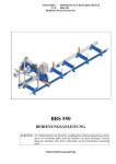
7.2 Meter components are packed into the boxes in accordance with drawings of
manufacturer.
In coordination with the customer FS delivery without transport container or in customer’s container is possible.
8
Safety precautions
8.1 Electric isolation of meter power circuits with a supply voltage 220 V stands a
test direct current voltage 2100 V during 1 minute without damages.
8.2 Electric isolation of meter power circuits with a supply voltage 36 V or 24 V
stands a test direct current voltage 700 V during 1 minute without damages.
8.3 Electric isolation of power circuits of device enclosure stands a test alternate current voltage 1500 V during 1 minute without damages.
8.4 Electric resistance of isolation for meter power circuits with a power supply voltage 220 V is not less than:
20 MOhm - while the temperature is 20 С and relative humidity is up to 80 %;
1 MOhm - while temperature is 35 С and relative humidity is 95 %.
8.5 Electric resistance of isolation for meter power circuits with a power supply voltage 36 V or 24 V is not less than 1 mega ohm.
8.6 Electric resistance between ground contacts of a three-polar plug of power cable
and metal parts of the calculator case is no more than 0.1 Ohm.
Electric resistance between ground contacts of three-polar sockets of device enclosure
and its case should be no more than 0.1 Оhm.
24
8.7 Working with meters it is necessary to observe operating safety precaution rules
for work with electrical facilities.
Warning! Using the transformer as the meter power supply with a power supply voltage 36 V or 24 V, input and output transformer windings should be galvanically separated
and a double or strengthened isolation should be provided between them.
25
9
Installation
9.1 Unpacking and degreasing
Unpacking and degreasing of meters are carried out after their being indoors within 2
hours, while ambient temperature varies from 10 up to 30 С and relative humidity is no more
than 80 %.
To make unpacking, please follow the instructions:
open packing boxes;
take a package with the calculator and operational documentation;
check up completeness of meters in accordance with the order (see Chapter 17);
take meter components from packing boxes, make an external survey and be convinced of absence of mechanical damages, coating infringements and isolation of
connecting cables.
9.2
Installation Requirements
9.3 Installation of meter components is carried out in accordance with chosen configuration, necessity of application of the additional equipment, and also parameters of heat
consumption object.
9.3.1 Basic schemes for meter installation according to their configurations are
represented in Appendix B.
The example for connection of additional equipment to meters of configuration 2 is resulted in the appendix C. Connection of the additional equipment is not obligatory and discussed with the consumer.
9.3.2 Climatic conditions in a room, where meter components are installed should be
as follows:
In a place for FS and RТD installation:
ambient temperature can vary from −40 C up to +70 C;
ambient humidity is up to 95 %, while temperature is 35 С;
In a place for calculator installation:
ambient temperature can vary from 0 C up to +50 C;
ambient humidity is up to 80 %, while temperature is 25 С.
Climatic conditions in a mounting place for the additional equipment should meet the conditions resulted in the operational documentation for this equipment.
9.3.3 External conditions have a great impact. It means that the device can be installed on the object where interference level has a bad influence on its work. Choosing an
installation place for the device it is necessary to avoid the vicinity of underground railway
(pulse interference in a power line), nearness of high-voltage lines, powerful electromotors
(splashes in a power line) and the equipment with big transformers (magnetic inductions). At
presence of interferences the length of communication lines between FS, RTD and the calculator should be minimal and their length is determined by a noise level on a certain object.
For reduction in a noise level from power line, installation of network radio-frequency
filters is recommended. The level of electromagnetic interferences can be lowered by additional measures on electromagnetic shielding, both the device and an interferer. The effec-
26
tive measures for reduction of interference influence are minimization of lengths of connecting lines.
9.3.4 Protection of places for FS and RTD installation from direct ingress of moisture, dirt, oils and aggressive liquids should be provided.
The content of acid and alkali fume in air of premises, where meter components are installed, should be within the limits of sanitary code and rules.
At outdoor FS installation it is recommended to provide protection against direct ingress of atmospheric precipitates on ultrasonic flow sensors.
FS installation in places with possible short-term water flooding is allowed while observing following protection measures for FS and entrance cables:
the lining of cables should be made in protective waterproof pipes, which are resistant to influence of an environment (including the increased temperature);
places for connection of protective pipes to ultrasonic flow sensors or RTD should
be protected from water influence by means of tight clutch, profile sealants or other
ways recommended by the manufacturer of protective pipes.
9.4 Installation of flow measuring section
FS installation place should be as much as possible removed from sources of vibrations,
jolting, electromagnetic interferences (electromotor, pumps, compressors, etc.). No electric
voltage relative to a protective contour of grounding in the place, where FS should be installed.
The distance between flow meter section and an installation place for the calculator
should be minimal and not exceed 100 m.
In all cases it is necessary to locate FS in the pipeline area providing its full filling with
water otherwise meters stop functioning, and malfunction (see Chapter 13 of OM) is diagnosed.
Flow meter sections can be installed in vertical position, however submission of the
heat-carrier thus should be carried out in a direction bottom-up for providing FS with water
filling.
Heat meter operation in special conditions (incomplete filling of FS with the heatcarrier or polluted heat-carrier) determines its location as resulted in figure 9.1. In this case
complete water filling of FS is guaranteed. The most polluted pipeline section appears in a
place below FS.
FS
Horizontal
15−20°
Drain
valve
Figure 9.1
For the removal of heat-carrier rests from the bottom part of the pipeline (see figure
9.1), it is possible to provide the drain valve.
At installation please follow the requirements resulted below.
The pipeline section chosen for FS cut-in, should be located in horizontal plane (a deviation from a horizontal within the limits of ± 20 °).
27
Bushes for flow sensors are also mounted in horizontal plane with a deviation from a
horizontal no more than ± 20 °.
Distances downstream of flow disturbances in accordance with specified meter accuracy should be not less than mentioned in the Table 9.1.
Таble 9.1
Flow Disturbance
Conical Contraction with an angle no more than
20 °
Single 90 ° Bend
Gate valves* or two 90 ° Bend in perpendicular
planes
Pump
7 DN
Modification М1
DN < 200
DN ≥ 200**
1 beam 2 beams
10 DN
15 DN 10 DN
10 DN
15 DN
15 DN
20 DN
50 DN
70 DN
15 DN
20 DN
20 DN
30 DN
90 DN
30 DN
Modification
М2
Remarks:
* Completely open globe valve is not considered as a disturbance.
** Designations «1 beam» and «2 beams» mean that flow measuring sections have one
diametric path and two-chord paths correspondingly.
The straight pipe section between two serial flow disturbances should be not less than 5
DN. Otherwise upstream straight section should be increased by the length equal to a difference (in millimeters) of the required and real distances between disturbances.
Distance downstream of FS should be not less than 5 DN for modification М2 and
10 DN for modification М1 for one-beam FS and 5 DN for two-beam FS.
If DN of supply pipeline and DN of straight sections are different then application of
conical contraction is required.
The straight pipe distance downstream a conical contraction should meet the requirements for all flow meters.
To calculate the length of straight sections we use distance equal to DN in mm for appropriate standard size of FS (DN 32 means 32 mm, DN 50 means 50 mm etc.).
It is not supposed to install any kind of disturbances on straight sections upstream of a
flow meter.
Internal diameter of a straight pipeline section should not differ more than on ± 5 %
from:
digital value of DN in mm for FS with DN20, DN32, DN50. In other words, nominal value of internal diameter of straight section should be 20 mm, 32 mm and
50 mm correspondingly;
real diameter of FS, which is resulted in Chapter 17 “Parameters and characteristics
of meter components” for FS with DN65…DN1000.
For modification М1 deviation of internal diameter of straight section is permitted, but
no more than + 5 % (negative deviation is not acceptable).
9.5
9.5.1
Installation of meter components
Installation of FS
9.5.1.1
FS is insertion type of a flow meter.
9.5.1.2 Delivery sets with FS of DN32 include special pipe branches (nipples),
which are welded to straight sections of the pipe during installation.
28
For the rest of FS the straight sections are included in delivery set according to customer’s request.
Pipe branch with sleeve nut, which is included in delivery sets for FS of DN20 and
DN32, is a part of straight section and applied for further welding to pipeline to create required distance of straight section.
The axis of a branch pipe and straight section should be a uniform coaxial line without
significant jogs and bends. Transition ‘jump’ from a branch pipe to a pipe should not exceed
0.8 mm (± 2.5%) for FS of DN32.
9.5.1.3 While connecting flow meter’s flange to the pipe, the flange bore can be
reamed to external pipe diameter with the least allowable tolerances. The schemes for flange
welding are resulted in Fig. 9.2 and Fig. 9.3.
Flange mounting to the pipeline should be carried out without metal sagging on the internal pipe surface. Otherwise change of velocity profile can lead to additional meter error.
After flow meter installation the flange painting should be done.
Figure 9.2
Figure 9.3
WARNING!
Please avoid welding of flanges to the pipeline if FS has been installed! It can lead to flow meter
damage because of overheating
9.5.1.4 Pressure losses
Pressure losses at maximal flow rate Qmax don’t exceed 0.085 kgf/сm2 (for all flow
meters, if there are no additional remarks).
Pressure loss for flow meters of DN32 (with straight sections DN 32) in kgf/сm2 is
shown on the plot (see fig. 9.4).
The curve 2 demonstrates pressure loss directly on the flow meter of DN32. The curve
1 demonstrates pressure loss on the flow meter, straight sections and conical 10° contractions, while installing the flow meter of DN32 on the pipe of DN 50.
29
P, kgf/сm2
0.2
1
0.15
2
0.1
0.05
0
0
5
10
20 Q, m3/h
15
Figure 9.4
For flow meters of DN50 the pressure loss is resulted in Fig. 9.5.
Pressure loss, kgf/cm2
0.3
0.25
0.2
0.15
0.1
0.05
0
0
20
40
60
80
Q, m3/h
Figure 9.5
9.5.2
Installation of flow sensors
9.5.2.1
DN1000.
The order for installation of flow sensors FlS is applied for FS of DN 32…
9.5.2.2 After FS installation on the pipeline it is necessary to install ultrasonic flow
sensors as follows:
30
clean a dust and dirt on internal surfaces of bushes if necessary;
for protection of fixing nut and flow sensor materials from diffusion with material
of FS it is necessary to grease a bush thread and a lateral cylindrical surface of ultrasonic flow sensors with graphite greasing;
FlS effective area (edge) should be cleaned from greasing;
insert ultrasonic flow sensors in bushes (pipe-bends) of flow measurement section.
Marking* is put on sensor cable outputs for modification М1. So FlS with marks
“11” (or “21” for the second flow measurement channel) should be inserted in first
(according to flow direction) FS bush, FlS with marks “12” (or “22” for the second
flow measurement channel) should be inserted in second (according to flow direction) FS bush **. To connect FLS of two-path flow meter it is necessary to follow
guidelines in the table 9.5
at tightening of flow sensor’s fixing nut the force put to a wrench should be equal to
40 … 45 N·m and provide a ‘zero’ gap between FS surface and FlS ring surface outside of its sealing gasket. For FlS installed in FS of DN32 the force is 18 … 20 N·m.
* On sensor cable outputs for modification М2 marking is not required.
** The instruction is obligatory only for meters of modification М1.
WARNING!
Ultrasonic flow sensors contain piezoceramic elements and thin-walled design elements, which have the increased fragility and do not permit shock and excessive compressing loads.
That is why
IT IS FORBIDDEN:
to swap around flow sensors of different channels;
to install flow sensors with marks “11” (“21”), intended for installation in the first
flow meter bush (according to flow direction), in the second bush and sensors with
marks “12” (“22”) to install in the first bush (the instruction is obligatory for meters
of modification М1).
to drop ultrasonic flow sensors or to knock on them at transportation and installation;
to carry out mounting and dismantling of FS with installed ultrasonic flow sensors;
to accomplish metalwork or welding works on the pipeline close to FS with the installed ultrasonic flow sensors;
to exceed the mentioned above force for tightening of FlS;
to dismount stuck to FS flow sensors, while turning them in bushes during regular
service.
9.5.2.3 For the removal of the flow sensor its design provides special elements.
The manufacturer has developed and can propose special removers or complete set of
design documentation for their manufacturing.
The soldering and pinout schemes for connectors of flow sensors are resulted in the appendix G.
9.5.3
Installation of temperature sensors
31
Temperature sensors (manufactured by SEMPAL Co.) RTD-S can be installed in two
ways:
by screwdriving in bushes (lugs) of the first type welded into the pipeline for direct
contact of the RTD with the heat-carrier;
by screwdriving in thermal pockets, which, in turn, are screwed in bushes (lugs) of
the second type. The last ones are welded into the pipeline for contact with the heatcarrier via a protective thermal pocket.
Choosing a way of RTD installation in the pipeline it is necessary to consider, that to
obtain a maximal accuracy of temperature measurement the sensitive element of RTD
should be arranged more close to an axis of the pipeline. There are five types of RTD with
length of 58, 80, 150, 310, 360 mm (type 4, 2, 3, 5 and 6 correspondingly) and variants of
their angular installation in accordance with specified requirement irrespective of pipeline
diameter. The inclination angle and depth of RTD immersing is provided with use of bushes
(lugs), the design of which depends on pipeline DN. Variants of RTD installation are given
in the table 9.2 and in figure 9.7. Variants of RTD installation in thermal pockets are given in
the table 9.3 and in figures 9.8, 9.9.
Warning! Applying lugs with inclination 45 or 60 °, it is necessary to provide a contact
of heat carrier with the bottom part of RTD, where thermosensitive element is located.
The installation place for each RTD included in delivery set is given on the meter’s
scheme for installation (see the appendix B). The RTD which measures temperature of the
heat-carrier (water) should be installed close to FS. The distance between the RTD and the
calculator should not exceed 100 m.
The RTD can be installed on the upstream or downstream sections of FS, but installation on the downstream section is preferable. While installing the RTD after FS, the distance
between the bush and FS should be not less than 5 DN and at installation before FS - not less
than 10 DN.
After bush welding, it is necessary to process its thread by tap М10х1.5 or М16х1.5
(depending on bush type).
While installing the RTD with inclination 45° or 60°, it is necessary to drill 10 mm hole
(16 mm for a thermal pocket) and to saw up to a necessary oval depending on thickness of a
pipe wall (see figure 9.6 and figure 9.8).
The sealing surface of the bush should be protected from splashes of the fused metal
during welding.
Before application of sealing gasket (fluoroplastic ring) a sealing surface of the bush
should be greased.
While screwing the RTD in the bush, the force put to a wrench of 200 mm length,
should be no more than 5 kg and provide hermetic seal. The deformation of fluoroplastic
gasket in the gap between sealing surfaces of RTD and the bush is not permitted.
After final installation of RTD in the pipeline, the bush and an external metal part of
RTD should be heat-insulated from an environment.
Before screwing the RTD in the thermal pocket it is necessary to be convinced of
cleanliness of a thermal pocket and to fill it on 1/8 of volume with high-temperature silicon
lubricant of any type.
The soldering scheme for RTD connectors is indicated in the Appendix G.
32
Table 9.2
DN,
Configuration of RТD,
nominal length
mm
(LTD, mm), type
32
SMP.405212.001-03
LRTD=58; type 4
50
65
80
100 SMP.405212.001-01
LRTD=80; type 2
125
150 SMP.405212.001-02
200 LRTD=150; type 3
≥250
Configuration variants for bushes of first Angle
type (internal thread of bushes М10х1.5) of inclination
Labeling
Marking
SMP.723144.007
1
45°
SMP.723144.008
2
60°
SMP.723144.009
3
90°
SMP.723144.007
SMP.723144.008
SMP.723144.009
Table 9.3
DN,
Configuration of thermal
mm
pocket, nominal length
(LTP), mm; nominal length
of RТD (LTD), mm
50
SMP.753137.002-03 LTP=56;
65
LRTD=58
80
100 SMP.753137.002-01
125 LTP=78.5; LRTD=80
150
SMP.302634.002
200
LTP=148; LRTD=150
≥250
1
2
3
45°
60°
90°
Configuration variants for bushes of Angle
second type (internal thread of bushes of incliМ16х1.5)
nation
Labeling
Marking
SMP.723144.008-01
5
60°
SMP.723144.009-01
SMP.723144.007-01
SMP.723144.008-01
SMP.723144.009-01
6
90°
4
5
6
45°
60°
90°
The RTD of type 5 and 6 installation is possible only in the thermal pocket.
33
Figure 9.6 Installation of RТD-S of type 2, 3 and 4 without thermal pocket
34
Figure 9.7 Installation of RТD-S of type 2, 3 and 4 with thermal pocket
35
Figure 9.8 Installation of RТD-S of type 5 and 6 with thermal pocket
36
9.5.4
Installation of pressure sensors
Pressure sensors are installed strictly in vertical position. The scheme of installation is
represented in the appendix H.
Application of pressure intake devices is obligatory!
9.5.5 Mounting of the calculator
The Calculator SMP.408843.003 can be mounted in horizontal position (on the table,
stand or shelf) or in vertical position (on the wall or in device enclosure).
For mounting the calculator special accessories in delivery complete set are provided.
The mounting scheme is given in the appendix D.
The grounding of the calculator should be strictly connected with grounding of a premise in which the device is installed.
9.5.6 Cabling
After installation of all meter components their bond by means of the connecting cables
from the delivery complete set is made in following sequence:
1) cabling;
2) cable connection to the calculator, RТD and ultrasonic flow sensors.
9.5.7 Cabling is carried out under following requirements:
cable mounting should exclude a possibility of its contact with pipelines and other
elements if their temperature is below a minus 40 С or above 70 С;
cable protection against mechanical damages should be carried out by cable grooming in pipes, hoses, ducts, etc. Cable grooming for one meter in one protective housing is permitted;
cable grooming of two and more meters should be provided in the protective housings separated from each other on a distance not less than 5 cm for prevention of
mutual electromagnetic inductions.
after cable grooming it is necessary to make their connection to meter components
considering marks of cables.
•
•
WARNING!
Grooming of connecting cables near power supply lines or in their (power lines)
protective housings is forbidden.
If the meter has 24 or 36 V power supply then arrangement of the calculator should
exclude an opportunity of accidental device connection to 220V power supply.
9.5.8 Cable connection to the calculator and to all sensors should be carried out as
follows:
define ‘switch’ positions on connectors;
accurately, without appreciable effort plug connectors. Mutual rotation is not permitted;
a sleeve nut should be twisted at the end.
While connecting sensors to jacks it is necessary to strictly follow the marks on device
cable and flow sensor cable outputs.
37
Table 9.4 Compliance of marking on communication lines with marking on connected to
them flow sensor cable outlets for meters with single-beam FS.
Cable function
(connected unit)
Marking on
device cable
FlS1 of channel 1
FlS2 of channel 1
FlS1 channel 2 (FlS3)
FlS2 channel 2 (FlS4)
11
12
21
22
Marking on flow sensor cable outlets
main (duplicate) and their arrangement relative to flow
For modification М1
For modification М2
Marking
Arrangement
Marking
Arrangement
11 (11р)
First downstream
11 (11р)
11 (11р)
12 (12р)
Second downstream
n/a
21 (21р)
First downstream
22 (22р)
22 (22р)
22 (22р)
Second downstream
Table 9.5 Compliance of marking on communication lines with marking on connected to
them flow sensor cable outlets for meters with two-beam FS.
Cable function
(connected unit)
FlS1 beam 1
FlS2 beam 1
FlS1 beam 2 (FlS3)
FlS2 beam 2 (FlS4)
Marking on flow sensor cable outlets
main (duplicate) and their arrangement relative to flow
Marking of flow sensor,
Marking of the bend,
Main (duplicate)
Main (duplicate)
11 (11р)
1 (5)
12 (12р)
2 (6)
21 (21р)
3 (7)
22 (22р)
4 (8)
Marking on
device cable
11
12
21
22
Table 9.6 Marking of device cable communication lines for connection of temperature sensors RTD, pressure sensors PT and external devices.
Cable function
(connected unit)
TS1
TS2
TS3
TS4
TS5
TS6
Marking on device cable
31
32
33
34
35
36
Cable function
(connected unit)
PT1
PT2
Interface RS232
Analogue outputs
Interface RS485
Marking on device cable
41
42
51
61
71
Structural and basic schemes of device cable are given in the appendix F.
The calculator should be powered by three-pole socket.
9.5.9 CAUTION! IT IS FORBIDDEN:
1 To break the procedure of cable connection according to marking (tables 9.4 – 9.6).
2 To swap around RTD of temperature sensors ТS1, ТS2, ТS3, ТS4, ТS5, ТS6 (see the
Appendix B) and pressure sensors PT1 and PT2.
3 To increase or shorten length of cables of ultrasonic flow sensors FlS.
4 To apply FS, RTD, ultrasonic flow sensors FlS and calculators from different delivery sets.
5 Cable twisting, kinking and sharp bends at connection to FlS is not permitted.
CAUTION!!!
If it was required to make welding during device commissioning, the meter
should be switched off and device cable should be disconnected from the calculator
housing. Otherwise the meter can be damaged.
38
10 Setting-up procedures
10.1 Before powering up the calculator, please check up the conformity of a power
supply voltage (specified on the calculator) to a real voltage.
10.2 If meters operate together with the external equipment (a personal computer, a
printer) they should be connected in accordance with the proper operational instructions.
10.3 Connect a power cable to a three-pole socket.
10.4 For comfortable work with the device (after its purchase and before installation)
and for check of device working capacity together with ultrasonic flow sensors it is necessary:
1) Assemble a flow meter section with rubber or paronite gasket (thickness of 1-2
mm) and technological cap at the end face, install it vertically, fix flow sensors, and
completely fill FS with water.
2) Check up all items in a mode «Indication of main parameters», check up all
items in a mode "Check" and also it is obligatory to provide zero setting in a mode
"Setup" to correctly repeat this operation while installing device on the object (the description of operating modes is also given in Chapter 11).
10.5 While installing device on the real object it is necessary to fill with water the
pipeline with installed flow measurement section. Run through FS the heat-carrier (water)
with increased volumetric flow rate during 10 minutes. Be convinced of no leakage in places, where meter components are installed, and no error messages on the digital display of the
calculator. The list of these messages is resulted in Chapter 13.
10.6 Accomplish mentioned hereinafter actions in a mode «Setup».
To login in a mode "Setup" see instructions described in item 11.2.4, the order of menu
access in a mode "Setup" is described in item 11.2.5, and also in Appendix E
In a mode "Setup":
set hydraulic zero for the channel of volume measurement;
input the temperature value of cold water into calculator memory (only for configuration 4);
set the proper units;
set a proper archiving format for the heat-carrier (water) volume data ;
input the pressure value of the heat-carrier in supply and return pipelines into calculator memory;
reset all integral meter parameters.
Warning!
Zero setting should be provided for all FS of DN less than 400 mm. For FS of
DN400 and more zero setting isn’t required. For FS, which nominal bore isn’t more than
400 mm cable connection to flow sensors should be done strictly with marking on FlS
and corresponding cable.
For zero setting following actions should be done:
39
Zero setting should be carried out not earlier than in 30 minutes after powering up
of the meter.
Cut off a heat-carrier (water) flow, thus FS should remain completely filled with
heat-carrier (water).
Provide zero setting according to menu item “Setup”.
In case of operation failure or wrong zero setting the measurement error increases and
can exceed permissible value. Reset of device readings at its commissioning is blocked, if
setting of hydraulic zero is not made. Detailed information about zero setting is given in Appendix J “How to set hydraulic zero”.
If during meter startup a reset of device readings was not provided, a proper warning
will be displayed on the indicator.
After ending of the above-stated operations meters are ready for functioning and set in
a mode «Indication of main parameters». Temperature values on the device indicator
measured by first two temperature sensors TS1 and TS2 are displayed.
10.7 To switch off the meter a 3-pole plug should be disconnected from a socket.
WARNING!
While in service it is forbidden to disconnect sensors, to change arrangement of sensors (to prevent such not authorized actions a mechanical socket sealing of all FlS,
TS, PT is stipulated), to switch off the calculator, to install meters on the pipeline
with incomplete (partial) water filling of FS or on the pipeline supplying the heatcarrier in steam condition. In all above-stated cases (except for device switching off)
the heat meter will register failure operating time, which is subtracted from the time
of the heat-carrier control. Power off time (switching-off time) isn’t considered during failure operating and would be displayed in a mode «Indication of additional
parameters» (see item 11.2.2) .
If the heat-carrier was cut off for a long time (interheating period, repair of heat system, etc.) and it had led to occurrence of stagnations in the pipeline (drains, a rust,
bubbles, etc.) it is recommended to switch-off the device or to provide the guaranteed absence of the heat-carrier in a flow measuring section (to block pipeline
valves and to drain the rests of water by means of the drain valve - see figure 9.1).
Scum on internal FS walls reduces the real FS diameter and can lead to overestimation of water and heat flow rate readings. Therefore it is necessary to provide maintenance service of meter every two years (see Chapter 12).
During each operation cycle (1 - 2 seconds) the heat meter carries out selfdiagnostics of a technical condition by several criteria. In case of measurement section failures, breakage of flow (temperature) sensor cables, absence of the heatcarrier, etc., storage of integral parameters (heat-carrier volume and mass, heat
energy and non-failure operating time) is discontinued and the error message is appeared (see Chapter 13).
40
11 The operating procedure
11.1 Requirements to the personnel.
The maintenance personnel should be acquainted with present OM completely. The
work with meters is permitted to persons acquainted with safety regulations on electrical facilities.
11.2 Structure of the menu of control of the meter.
Control of the meter (a readout and specification of operating mode and meter parameters) is carried out by means of proper menu item selection.
Menu of control of the meter consists of a group of message lines (menu items), serially displayed on the meter indicator.
Use of the menu (switching of items) allows to get the information about measured parameters of the heat-carrier, parameters of the meter and also to carry out meter verification
and to modify meter parameters by results of its metrological performance control.
Selection of menu items is carried out by means of pressing buttons on the calculator.
Sequence of operations to select the certain menu item and to input parameter value or to select a parameter from the list is given in the Appendix E.
All measured quantities, meter parameters and commands for meter control are combined in some sections - control modes of the meter.
Some service modes (‘Setup’, ‘Verification’) are protected from non-authorized access
by the password.
The meter menu structure is resulted in the table 11.1, and its graphic representation - in
figure 11.1.
11.2.1 ‘Indication of main parameters’ Mode.
The arrangement of items in a mode ‘Indication of main parameters’ is resulted in chapter 1 of the table 11.1 and in figure 11.1. The list and the content of items are resulted in the
table 11.2.
The order of running through the menu in a mode ‘Indication of main parameters’ is
resulted in Appendix E, in figure E-1.
The device switches to mode ‘Indication of main parameters’ after power up, after
setting-up in a mode ‘Setup’ (see chapter 10 of OM), after ending of operating in service
modes (‘Check’, ‘Verification’) and also at automatic switching to mode ‘Indication of
main parameters’.
Depending on meter configuration the proper measured parameters, which meet to a
given configuration, are displayed on the calculator indicator.
Table 11.1
How to enter the
menu section
Section*
Power switching-on
1
Switch to item ‘Select mode’
2
Name of menu
item
Section assignment
Mode of indica- Indication of main measured parametion of main pa- ters and current time
rameters
Selection of a Selection of a mode in a mode list
mode
41
Name of menu
Section assignment
How to enter the
Section*
item
menu section
Selection of a mode
2.1
Additional para- Indication of heat-carrier mass, time of
meters
correct work and power off time
2.2
Check
Indication of heat meter parameters,
number of entries into service modes
and print out of archives
2.3
Setup
Accomplishment of proper operations
at heat meter commissioning
42
2.5
Verification
Performance of proper operations during verification (the control of metrological performance)
2.6
МDМ/RЕG**
MDM/REG setup. The description of
modes for built-in unit MDM/REG you
can find in a detached manual.
2.7
Credit
tion**
prolonga- Input a password for credit prolongation. It is indicated only when mode
‘Credit’ is active.
Fig. 11.1
43
Enter password
‘МDМ/RЕG’
Section 2.6
‘МDМ/RЕG’
Enter password for
prolongation of ‘Credit’
Enter password
‘Verification’
Section 2.5
‘Verification’
Section 2.8
Enter password
‘Setup’
Items of section
‘МDМ/RЕG’
Sections 2.5.1...2.5.7
of mode ‘Verification’
Section 2.2.9
‘Cold water parameters’
Section 2.3.8
‘Service/Out of service’
Section 2.3.6
‘Archive format’
Section 2.2.8
‘Setting’
Section 2.2.6
‘RTD parameters’
Section 2.1.5
‘Break time’
Section 2.3.5
‘Unit system’
Section 2.3.7
‘Set time’
Section 2.2.5
‘FS parameters’
Section 2.1.4
‘Work time’
Section 2.3.4
‘PT parameters’
Section 2.2.7
‘Entry counter’
Section 2.2.4
‘Serial number’
Section 2.3.3
‘Cold water temperature’
Section 2.2.3
‘View archive’
Section 2.1.2
‘Маss 2’
Section 2.1.3
‘Power time’
Section 2.3.2
‘Pressures’
Section 2.2.2
‘View journal’
Section 2.3.1
‘Set Zero’
Section 2.1.1
‘Маss 1’
Menu organisation
Section 2.3
‘Setup’
Section 2.2
‘Check’
Section 2.1
‘Indication of additional
parameters’
Section 2
‘Select mode’
Section 1
‘Indication of main
parameters’
Power on
Table 11.2
Menu item*
1.1
1.2
1.3
1.4
1.5
1.6
1.7
1.8
1.9
1.10
Name of menu item
Temperature t 1, °С
Temperature t 2, °С
Temperature t 3, °С
Temperature t 4, °С
Temperature t 5, °С
Temperature t 6, °С
Flow rate1, m3/h
Flow rate 2, m3/h
Pressure Р1, kgf/сm2
Pressure Р2, kgf/сm2
Volume 1, m3
Volume 2, m3
Mass leak, ton/hour
Heat power, Gcal/h
Heat energy 1, Gcal
Heat energy 2, Gcal
Current time
Notes
Indication of temperatures, measured by temperature sensors ТS1 and ТS2
Indication of temperatures, measured by temperature sensors ТS3 and ТS4
Indication of temperatures, measured by temperature sensors ТS5 and ТS6
Indication of heat-carrier (water) volumetric flow
rates in FS1 and FS2.
Indication of overpressure, measured by pressure
transducers PT1 and PT2.
Indication of heat-carrier (water) volume in FS1
and FS2.
Indication of the calculated mass leak of the
heat-carrier (water) (only for configurations 4, 5,
7),
Indication of the heat power
Indication of the heat energy for FS1 and FS2 (or
total heat energy for configurations 4, 7, 9)
Indication of astronomical time and current data
* The numerical item designation accepted within this OM for the description of the
menu structure (it is not displayed on the indicator of the calculator).
11.2.2 ‘Indication of additional parameters’ Mode.
The arrangement of items in a mode ‘Indication of additional parameters’ is resulted in
item 2.1 of the table 11.1 and in figure 11.1. The list and the content of items are resulted in
the table 11.3.
The order of running through the menu in a mode ‘Indication of additional parameters’ is resulted in Appendix E, in figure E-2.
Таble 11.3
Menu item
Name of menu item
Explanation
2.1.1
2.1.2
2.1.3
2.1.4
2.1.5
Mass 1, ton
Mass 2, ton
Power time, h
Work time, h
Break time, h
Indication of heat-carrier (water) mass in FS1
and FS2.
Indication of power on time
Indication of correct work time (work time)
Indication of power off time (break time)
11.2.3 At occurrence of worst-case situations in modes ‘Indication of main parameters’ and ‘Indication of additional parameters’ a code and character of malfunction (see
Chapter 13) are displayed on the device indicator.
44
11.2.4 ‘Check’ Mode.
The arrangement of items in a mode ‘Check’ is resulted in item 2.2 of the table 11.1
and in figure 11.1. The list and the content of items are resulted in table 11.4.
The order of running through the menu in mode ‘Check’ is resulted in Appendix E, in
figures E-3…E-6.
The mode ‘Check’ provides for revision of archive data and events journal (operator
actions), indication of parameters, which are necessary for control, adjustment of device indicator contrast and adjustment of a bitrate within interface RS-232C. The mode ‘Check’
does not interrupt measuring process and can be used both the energy-supervisor, and the user (see table 11.4.).
Table 11.4
Menu item Name of menu
Explanation
item
n/a
n/a
2.2.1
View journal
Displaying of event journal
2.2.2
View archive
2.2.3
Displaying of hourly, daily error archives with error codes
Serial number
2.2.4
Indication of calculating unit number given by the manufacturer, configuration and the program version for the meter
FS parameters
2.2.5
Indication of diameter values, conversion ratios and distances between transmitters of FS1 and FS2, resulted in
Chapter 17 of OM.
RTD parameters Indication of temperature coefficients of NSC RТD (coeffi2.2.6
cients Kdl1, Krc1, Kdl2, Krc2, Kdl3, Krc3, Kdl4, Krc4), set
by the manufacturer (see Chapter 17 of OM).
Entry counter
Indication of number of entries in modes ‘Setup’ and ‘Veri2.2.7
fication’
Setting
2.2.8
Step adjustment of picture contrast on the calculator indicator
and a bitrate for RS-232 is carried out
Cold water pa- Indication of temperature and pressure in cold water supply
2.2.9
pipeline (configurations 4, 7, 9)
rameters*
*indicated only for proper meter configuration
Storage of the archival information begins after reset of integral parameters during meter startup. Hourly archive history is 70 days, daily archive history is 1 year. It means, that
the archive contains stored data for last 70 (365) days preceding a current hour.
All users’ actions carried out in modes ‘Setup’ and ‘Verification’ are registered in the
event journal. They can affect the measuring result.
Calculator carries out automatic switch to summer and winter time.
Automatic switching to summer time can be turned off by user in the mode ‘Setup’.
11.2.5 Description of the mode ‘Enter password’.
45
Entry into service modes ‘Setup’ and ‘Verification’ is permitted only after entering
the proper passwords to avoid non-authorized access to parameters saved in calculator
memory. Password input is requested after the user has chosen a proper mode in the menu.
The manufacturer set the following standard passwords for service modes (see table
11.5) at device shipment:
Table 11.5
MODE
STANDARD PASSWORD
25205757
‘Setup’
31415926
‘Verification’
On customer’s demand the manufacturer can set INDIVIDUAL PASSWORDS for service modes that is equivalent to additional ELECTRONIC SEALING of the calculating unit
and provides inaccessibility of unauthorized users to the saved up measuring information.
The password is represented by 8-digit integer number, which is necessary for getting
access to one of service modes.
Symbols * on the indicator mark bits into which it is necessary to input password digits.
Non-masked (open) value of an input digit is displayed only in that bit, in which input
of its values (editing) is made.
Pressing the button
("To the right") moves the cursor on one bit to the right, allowing to change separate bits of the password.
Pressing buttons
and
(«Up» and «Down») leads to a change of the edited digit.
Pressing the button
(«To the left») means ending of password input.
If during 10 minutes there was no pressing of any button the meter is switched from a
mode ‘Enter password’ to mode ‘Indication of main parameters’.
In figure 11.2 the example of password input for entry in a mode ‘Setup’ is given.
Figure 11.2
11.2.6 ‘Setup’ Mode.
The arrangement of items in a mode ‘Setup" is given in item 2.3 of table 11.1 and in
figure 11.1. The list and the contents of items are resulted in table 11.6.
46
The order of running through the menu in a mode ‘Setup’ is resulted in appendix E, in
figures E-7…E-12.
The ‘Setup’ mode is used by consumer during meter commissioning for hydraulic zero
setting in volume measurement channels, setting of units, input of necessary parameters of 1st and 2-nd channels and also for total device reset (see table 11.6).
Table 11.6
Menu item
Name of menu item
Explanation
Set zero
Setting of hydraulic zero, which is necessary for
2.3.1
device commissioning
Pressures
Input of internal pressure values in supply and
2.3.2
return pipelines for channels 1 and 2
2.3.3
Cold water temperatures* Input of cold water temperature value (only for
configuration 4)
Enter the number of used PT and their parame2.3.4
PT parameters *
ters
Setting of unit system (СGS or SI)
2.3.5
Unit system**
2.3.6
Archive format**
2.3.7
Set time**
2.3.8
Service
2.3.9
Out of service
Archive format for heat-carrier flow rate is selected (by volume or by mass).
Input of current values: year, month, day of
week, hours, minutes
Total nulling of all stored parameters and archive
(can be seen only after shipment or after ‘Out of
service’ mode)
Editing of meter parameters is permitted (can be
seen only after ‘Service’)
* indicated only at proper meter configuration
The notice. Items, marked by ** are accessible only after ‘Out of service’.
11.2.7 ‘Verification’ Mode.
The ’Verification’ mode is intended for estimation of measurement errors and calculation errors of some basic meter metrological parameters and also for verification of correctness of their indication.
The ‘Verification’ mode is used for automation of periodic verification of heat meters.
Verification can be carried out only by manufacturer or his authorized representative with
participation of state verification officer.
This mode has been specified in verification instruction.
THE NOTICE: While entering ‘Verification’ mode the saved up integrated parameters are not misrepresented. To see number of entries into ‘Verification’ mode, switch to
‘Check’ mode.
11.2.8 Additional modes.
11.2.8.1 ‘МDМ/RЕG’ Mode.
47
It is intended to set parameters of the built-in MDM/REG unit, notably parameters of
communication for the MDM unit and parameters of linear and threshold outputs for the
REG unit including parameters of regulators (if any from linear outputs is used for regulation).
The arrangement of items in the ‘MDM/REG’ mode is resulted in item 2.6 of the table
11.1 and in figure 11.1. The list and the content of items are resulted in special manual if this
mode is ordered by consumer.
11.2.8.2 ‘Credit prolongation’.
It is intended to input a password for credit prolongation.
11.3 Malfunction diagnosis.
The calculator carries out diagnostics of malfunctions and gives out malfunction messages on the indicator. The detailed description of the device functioning in this mode is resulted in Chapter 13 of OM.
48
12 Servicing
12.1 The Instruction to the representative of inspecting service
12.1.1 The SVTU-10М heat flow meter is protected from consumer intervention as
well as intervention of heat supply organization. Any changes of a heat meter parameters can
be carried out only in ‘Setup’ and ‘Verification’ service modes. To except a nonauthorized access into device functioning process and prevent possible attempts to change
any device constants (calibration factors of thermoresistor Kdl and Krc, conversion ratio on
flow rate, geometrical parameters of a flow meter section), the fact of login or running
through these modes is fixed in the ‘Check’ mode (see appendix E). The opportunity to
check inputs in the specified modes is equivalent to a mechanical sealing (i.e. it substitutes
mastic seals, branded labels, etc.), so it is electronic way of calculator sealing. Therefore
the basic attention should be paid to the number of entries into service modes. Difference of
this number from the recorded one at the moment of device commissioning (release date according to the certificate) should be considered as damaging of the seal installed by inspecting organization. The possibility of mechanical sealing of the calculating unit with the use of
sealing cups with holes on device case is stipulated.
12.1.2 In doubts of heat meter correct installation or operation it is necessary to enter
into the ‘Check’ mode and to compare correctness of the entered values for RTD temperature coefficients, FS exact diameters, distances between flow sensor transmitters and FS
conversion ratios to the data resulted in Chapter 17 ‘Parameters and characteristics of meter
components’. Thus compared values can differ in limits, which are not exceeding units mentioned in Chapter 17 of this OM.
12.1.3 It is necessary to consider, that a heat meter commissioning begins with reset
(nulling) of its integrated indications (the saved up measuring data). Reset of indications also
should be carried out after meter repair or verification.
12.1.4 Difference between power on time and time of correct work means that a heat
meter operated incorrectly (switching-off, breakage or short circuit of sensor cables, absence
of the heat-carrier, etc.). Therefore sealing of flow sensors or their connectors is not obligatory. However, the possibility of mechanical sealing for flow sensors and their connectors
with a use of proper holes in clamping nuts of FlS and connector cases is stipulated.
12.1.5 To except a non-authorized influence on RTD parameters and so on temperature measurement accuracy it is necessary to mechanically seal up the temperature sensor using a hole in RTD case.
12.2 Maintenance service is carried out by the representative of service organization.
During servicing it is necessary to carry out the security measures given in Chapter 8.
12.3 Meters are put to two servicing types: #1 and #2.
12.4 Servicing #1 is carried out on a meter operation place twice a year and includes
external examination and check of working capacity.
Check visually:
no leak in places of meter installation;
reliability of contact joints;
no mechanical damages on plastic details;
49
safe isolation of connecting cables;
measuring data output in accordance with items 11.2.1 and 11.2.2.
After ending of heating season it is necessary to make cleaning of flow sensor surfaces using washing-up liquids, weak solutions of alkalis or acids (without mechanical cleaning). If heat meter was out of service for a long period of time it is recommended two ways:
to switch-off the device or to provide the guaranteed absence of the heat-carrier in a flow
measurement section.
12.5 Servicing #2 of meters is carried out annually.
At servicing #2 following operations should be carried out:
operations, provided by servicing #1;
dismantling and cleaning of FS according to item 12.5.1;
dismantling and cleaning of RТD.
12.5.1 Dismantling and cleaning of FS is carried out in the following way:
to dismantle ultrasonic flow sensors;
to detach FS from the pipeline;
to carry out external examination of FS and, if necessary, to clean mechanically its
internal surface from sediment;
to wash out internal FS surface by a solution of a synthetic washing-up liquid of any
type, and then by water.
12.6 Meters are presented for verification after servicing #2. Calibration interval is 4
years. Calculator, ultrasonic FlS, temperature sensors, flow measuring sections are presented
for verification.
Metrological verification of meter modification М2 can be carried out according to ‘no
water’ method using flow rate simulator IMR-01 (see table 4.1 of verification method
SMP.407251.003 И2).
The test for flow meters (if necessary) can be carried out applying certified flow measurement sections.
The test for meter modification М1, which includes FS with nominal diameter more than
DN 100, is carried out applying certified flow measurement sections of DN 100.
13 Typical faultinesses and methods of their elimination
While in operation, the meter constantly checks working capacity both the internal units
and the sensors (of flow rate, temperature, etc.) connected to the meter.
Diagnosed errors are subdivided into groups according to a priority (importance for realization of normal measurement). The number of group less, the error importance is more.
The error code includes its number and number of the measurement channel, in which there
was an error.
Error displayed on the indicator looks as follows (example):
Err. 1.3.1
TS1 short
50
Here 1.3.1 is error code, which consists of group (first digit), error number (second digit) and measurement channel number (third digit). In this case measurement channel number is a number of temperature sensor. One error is shown on two indicator lines. So, two
different errors can be displayed simultaneously (indicator has 4 lines).
As it was specified above, the number of error group is less, the priority of error is
higher. Surely most significant errors are system errors. These errors of the internal meter
equipment make meter functioning impossible. So none of the parameters are measured and
stored. Such errors are displayed on the indicator as follows (example):
System
error 02
Number means an error type. System errors are registered in the event journal with
some text decoding, if possible.
In case of system error the meter should be delivered to manufacturer for repair.
13.1 Error group «0».
In group «0» following errors are included:
«0.1.0» - Error of flow measurement section. Flow measurement in both channels is
impossible.
«0.2.0» - Error of ADC. Temperature measurement in all channels is impossible.
«0.3.0» - Error of communication with МDМ. It does not affect measurements and
calculations. It makes impossible data collection through external communication
lines. The REG Unit (if it is installed) does not display the information on analog
and switch outputs (including regulating channels).
13.2 Error group «1».
This group includes the errors referring to temperature measurement (the sign «x» specifies number of the channel):
«1.1.0» - break of one or some ТS from the set ТS1...ТS3.
«1.2.0» - break of one or some ТS from the set ТS4...ТS6.
«1.3.x» - fault of ТSx.
«1.4.x» - ТSx is failed. Resistance of mentioned ТS is out of specified limits.
«1.5.x» - error of ТSx factors. It was an error during manual input of calibration
factor for mentioned ТS. This error can appear after ТS calibration and manual input of new factor values during meter verification.
«1.6.x» - ТSx is below the tolerance. Measured by TS temperature is lower than acceptable one (is lower than -50 C).
«1.7.x» - ТSx is over the tolerance. Measured by TS temperature is higher than the
maximum (is higher than +150 C).
If ТS with an error is taken into flow rate measurement process, then proper flow measurement channel cancels all measurements. If ТS is used for heat energy calculation then
heat energy is not determined.
13.3 Error group «2».
This group includes the errors of pressure measurement (the sign «x» specifies number
of the channel):
51
«2.1.x» - PSx is below the tolerance. Measured pressure is below zero. It can be
caused by object conditions (underpressure was created), or with breakage of corresponding PS.
«2.2.x» - PSx is over the tolerance. Measured pressure is above 20 kgf/сm2. It can
be due to the fact of increased pressure on the object and faultiness of PS.
Pressure measurement errors don’t affect flow rate measurement and heat energy calculation.
13.4 Error group «3».
This group includes the errors referring to flow rate measurement (the sign «x» specifies number of the channel):
«3.1.x» - measurement by FSx. Flow measurement in mentioned FS is impossible.
This error can be caused by the fact of:
faultiness of flow sensors;
faultiness of flow sensor cable – brake or fault;
no water in FS.
«3.2.x» - temperature of FSx. Because of malfunction of TS, which measures temperature in specified FS, a flow rate measurement is impossible. This error always
takes place with an error of measurement by TS. This error is displayed (and is
brought in error archive) to define interrelation between a temperature measurement
error and a flow rate measurement error.
«3.3.x» - high speed in FSx. The volumetric flow rate in mentioned FS exceeds
maximum value for this FS type more than twice.
If the error has been registered in the flow measurement channel, which is used for heat
energy calculations then heat energy is not calculated.
13.5 Error group «4».
This group includes the errors referring to heat energy calculation (the sign «x» specifies number of the channel). Here the errors in temperature ratios, which are necessary for
heat energy calculation, are analyzed:
«4.1.x» - tret > tsup + 2.5 C. The temperature of the return pipeline exceeds the
temperature of supply one more than on 2.5 C. Heat energy calculation is impossible. If excess is in a range: 0 up to 2.5 C, a temperature difference is accepted equal
to 0, and the error is not registered.
«4.2.x» - tcw > tsup + 2.5 C. The temperature of cold water exceeds water temperature in supply pipeline more than on 2.5 C. Heat energy calculation is impossible. If
excess is in a range: 0 up to 2.5 C, a temperature difference is accepted equal to 0,
and the error is not registered.
«4.3.x» - tcw > tret + 2.5 C. The temperature of cold water exceeds water temperature in return pipeline more than on 2.5 C. Heat energy calculation is impossible. If
excess is in a range: 0 up to 2.5 C, a temperature difference is accepted equal to 0,
and the error is not registered.
«4.4.x» - tHWS > tsup + 2.5 C. The temperature of hot water supply system HWS exceeds water temperature in supply pipeline more than on 2.5 C. Heat energy calculation is impossible. If excess is in a range: 0 up to 2.5 C, a temperature difference
is accepted equal to 0, and the error is not registered.
These errors don’t affect flow rate and temperature measurements.
52
In hourly and daily archive printouts there is a value of error appearance duration (Тerr)
for the first and second flow measurement channels. This value includes the errors referred
to flow measurement channel and errors, which lead to impossibility of flow rate measurement. Errors of a flow meter and errors of temperature measurement are included here.
Printouts have a field ‘Error types’, in which presence of certain error type is displayed.
In total up to three various types of errors can be displayed within an hour and up to 5 types
of errors can be displayed within a day. The error is displayed on printout only if its duration
exceeds 1 minute.
Errors are displayed by letters of the Latin alphabet. The certain letter meets to each
type of errors:
А – system errors (error group 0);
B – temperature measurement errors (error group 1);
С – flow rate measurement errors (error group 3);
D – pressure measurement errors (error group 2);
E – heat calculation errors (error group 4);
For example, record ‘BD’ means, that there were errors of group 1 and group 2. More
detailed information on these errors can be taken in the error archive printout.
In error archive printout the error code in the above described format and duration of
this error in hours are mentioned. Within one hour up to 3 polytypic errors can be registered
(in archive) and for a day - up to 5 polytypic errors can be registered. If the number of errors
is more than it was mentioned, than the most significant errors are stored. For example, the
error of one TS can cause some more other errors, so only error of ТS will be displayed.
The list of certain faultinesses and methods of their elimination are resulted in table
13.1.
Тable 13.1.
Appearance of faultiness
Possible reason
Method of elimination
To eliminate a break (to plug
1. There is no indication on Breakage of a calculator
the display
power cable, or cable is
a cable)
unplugged.
2. The meter does not react
The calculator is faulty
To repair the calculator
on button pressing
The notice: A repair of the calculator is made by specialized manufacturing division.
14 Storing
14.1 Heat meter storing can be made in heated or unheated storehouses.
Meter life cycle:
in heated storehouse – no more than 10 years;
in unheated storehouse - no more than 5 years.
14.2 Storage conditions for meters:
in heated storehouse:
ambient temperature can vary from 0 up to 50 С;
53
relative air humidity is up to 80 %, while temperature is 30 С and below without
moisture condensation;
in unheated storehouse:
ambient temperature can vary from minus 5 С up to 50 С;
relative air humidity is up to 95 %, while temperature is 35 С and below without
moisture condensation.
14.3 At long-term storage in unheated storehouse meters should be placed in an additional cover from a polyethylene film.
15 Transportation
15.1 Meters can be transported by all modes of transport. Their packing should provide protection against direct influence of atmospheric precipitation.
While transporting by air transport, meters in packing should be placed in hermetically
compartments.
15.2 Transportation conditions:
ambient temperature:
for calculator can vary from minus 20 С up to 50 С;
for FS can vary from minus 50 С up to 50 С;
relative air humidity is up to 98 %, while temperature is 35 С;
transport jolty with acceleration 30 m/sec2 , while frequency varies from 80 up to
120 beats per minute.
15.3 Meters are steady against influence of sinusoidal vibrations, while frequencies
vary from 5 up to 35 Hz with amplitude up to 0.35 mm.
15.4 At shipment and unloading it is not permitted to throw meters.
At shipment in vehicle FS and packing box with the calculator should be fixed with the purpose to except any moving.
16 Guarantee of manufacturer
16.1 Manufacturer guarantees that produced heat meters meet to all requirements of
their specifications within 48 months from the moment of shipment if the consumer observes
the following conditions:
installation, starting-up and adjustment of a heat meter is made by the organization,
which has the manufacturer’s sanction on carrying out given works;
presence in section 19 of OM a mark of the organization, which has provided installation, starting-up and adjustment of a heat meter;
conditions of service, transportation and storage meet to requirements in Chapters 811, 14 and 15 of present Operating manual.
16.2 Guarantees are extended on defects of meter components in delivery complete
set in case of manufacturing defects, defects of materials and componentry.
16.3 Guarantees provide replacement of defective details and check of meter working
capacity by manufacturer.
16.4 It is necessary to deliver the faulty device to manufacturer for testing and repair.
54
16.5 It is not allowed to open the calculating unit (to break seals) before returning the
device to manufacturer.
16.6 Guarantees do not provide expenses indemnification for dismantle, return and
repeated installation of the device, and also any secondary losses caused by malfunction.
16.7 In case of malfunction identification during a warranty period the consumer
should report unsatisfactory condition of the equipment to manufacturer:
SEMPAL Co. LTD
3 Kulibina Str., Kyiv, Ukraine, 03062
Phone/Fax: (+38 044) 239-2197, 239-2198.
16.8 Do not put in claims to a heat meter in following cases:
installation, starting-up and adjustment have been carried out by organization without manufacturer's license on carrying out of such works;
damage of seals on the calculating unit;
the expiration of a warranty period;
violation of service, storage and transportation regulations stipulated by the operational documentation.
16.9 After ending of a warranty period or loss of warranty service right the manufacturer makes repair of heat meters for a fee.
55
56
57
Appendix А
Order information
58
Appendix B
Basic circuits of meter mounting for different configurations
Configuration 1
Calculator
(Flow meter)
”12”
FlS2ДР1
ТS1
FlS1
”11”
ДР1
FS
Basic function is volume measurement
One flow meter
Configuration 2
Supply
pipeline
Calculator
(Heat meter)
FS
ТS1
FlS2
“11”
Return pipeline
“12”
FlS1
ТS2
Object
of heat supply
Basic function is heat energy measurement
Heat meter for closed heat supply system
The notice. Numeration of flow sensors and marking of cables are indicated according
to the table 9.3.
59
Appendix B
Configuration 3
Flow meter
Calculator
FS1
FlS2
Water supply pipeline
FlS1
ТS2
FlS4 Water supply pipeline
ТS1
“11”
Flow meter
“12”
“22”
FS2
Basic function is volume measurement
“21”
FlS3
Two independent flow meters
Configuration 4
Calculator
(Heat meter)
“12” Supply pipeFlS2
line
ТS1
“11”
Return
“21”
FlS3
FlS1
FS1
pipeline
ТS2
“22”
Object
of heat supply
FlS4
FS2
Basic function is heat energy measurement,
cold water temperature is set programmatically
Heat meter for open heat supply system
without cold water supply pipeline
The notice. Numeration of flow sensors and marking of cables are indicated according
to the table 9.3.
60
Appendix B
Configuration 5
Heat meter
Supply
pipeline
Calculator
FS1
ТS1
Flowmeter
“12”
FlS2
“11”
FlS1
FS2
ТS2
Return pipeline
“22”
Object
of heat supply
“21”
FlS3
FlS4
Basic function is measurement of heat energy, additional function is measurement
of heat-carrier volume in return pipeline.
Heat meter for closed heat supply system
with check flow meter on the return pipeline
Configuration 6
Heat meter
Calculator
Supply
pipeline
Flow meter
“12”
FlS2 FS1
ТS1
“11”
Object
of heat supply
FlS1
ТS2
Return pipeline
“22”
FlS4
ТS3
Water supply pipeline
“21”
FS2
FlS3
Basic function is measurement of heat energy, additional function is measurement of
cold or hot water volume in water supply pipeline.
Heat meter for closed heat supply system
and independent flow meter
The notice. Numeration of flow sensors and marking of cables are indicated according
to the table 9.3.
61
Appendix B
Configuration 7
“12”
ТS1
Supply pipeline
FlS2
“11”
FlS1
FS1
TS2
FlS3
“22”
Return pipeline
ТS3
Object
of heat supply
“21”
FlS4
FS2
Cold water pipeline
Basic function is measurement of heat energy, temperature of
cold water is measured
Heat meter for open heat supply system with cold water supply pipeline
Configuration 8
Heat meter 1
Calculator
Supply
pipeline
Heat meter 2
“12”
ТS1
Return
pipeline
Supply
pipeline
Return
pipeline
FlS2
“11”
ДР1
FS1 ТS2
Object
of heat supply
“22”
ТS3
FlS4 FS2
“21”
FlS3
TS4
Object
of heat supply
Basic function is measurement of heat energy on two objects
of heat supply
Two independent heat meters for closed heat supply system
The notice. Numeration of flow sensors and marking of cables are indicated according
to the table 9.3.
62
Appendix B
Configuration 9
FS1
“12”
Supply pipeline
“11”
FlS1
ТS1
Source of
FlS2
heat supply
ТS2
“22”
FlS4
FS2
Return pipeline
“21”
ТS4
Feeding pipeline
FlS3
ТS3
Cold water pipeline
Basic function is measurement of heat energy on object of heat
supply
Heat meter with flow measurement in supply and feeding
pipelines
63
Appendix C
Connection to additional device examples
Output configuration I (No built-in
МDМ/RЕG unit)
Connector (9 cont., female)
Interface 1
Х1
Х12
SVTU-10М
Calculator
to PC
51
Х13
not used
Connector (9 cont., male)
Housing for connectors
Figure C-1
Output configuration II (built-in MDM
unit without REG unit)
Connector (9 cont., female)
Interface 1
SVTU-10М
Calculator
Х1
Х12
to PC
51
Built-in МDМ unit
Х13
To modem
Connector (9 cont., male)
Housing for connectors
Figure C-2
The notice. Numeration of communication lines in figures is indicated according to the
table 9.4.
64
Appendix C
Output configuration III (built-in MDM
unit with RS485 but without REG unit)
Connector (9 cont., female)
Interface 1
SVTU-10М
Calculator
Х1
Х12
to PC
51
Built-in unit МDМ
To modem
Х13
Connector (9 cont., male)
Interface 3 (RS485)
71
RS485 link
Connector (9 cont., female)
Figure C-3
Output configuration IV (built-in MDM
unit with RS485 and with REG unit)
Connector (9 cont., female)
Interface 1
SVTU-10М
Calculator
Х1
Х12
to PC
51
Built-in МDМ unit
to modem
Х13
Connector (9 cont., male)
Interface 3 (RS485)
71
RS485 link
Connector (9 cont., female)
Interface 2
Connector (9cont.)
61
Analog outputs 1, 2
Threshold output
Socket Plug
Figure C-4
The notice. Numeration of communication lines in figures is indicated according to the
table 9.4.
65
Appendix C
Use of RS485 Interface
While using RS485 interface it is possible to connect simultaneously some meters (or
other SEMPAL devices) and to have access to any of them. For this the only one device
should be with an output to external lines.
RS232
Modem or direct communication
with PC
Transducer RS232/RS485
or
RS485
Flowmeter 1
Flowmeter 2
Flowmeter n
PC
RS485
Flowmeter 1
Flowmeter 2
Flowmeter n
The total length of communication line RS485 should not exceed 2 km. Thus devices
should be connected by ‘queue’. On the ends of a connecting cable the terminating resistances (120 Ohm) (crossbars between contacts 7 and 8 of sockets are unsoldered) should be
installed. The scheme for connecting cable RS485 (it is mounted by the user) is given below.
Installation should be accomplished by twisted pair.
Connectors of a connecting cable are attached to a connector 71 of device cable on each
meter.
Figure C-5
66
Appendix D
Overall and connecting dimensions of calculator
67
Appendix E
Meter control menu
Reference designations
The buttons below have the following meanings:
- «Right»,
- «Up»,
- «Down»,
- «Left».
Result from pressing a corresponding button
(Note: in this case from pressing the
button)
«Channel 3»
Continuation is followed on a next
page with the corresponding title
"Channel 3"
Menu items denoted as ( ) are indicated only for corresponding meter configuration.
For example, temperature of cold water is shown only for configurations 4 and 9.
Showing menu on display
SETUP
Unit system
Archive format
DST
” point to a chosen item on the screen.
Symbols “
Pressing the button “ ” will execute the chosen item. To
return to the previous menu press “ ”.
Symbols “ ” and “ ” show previous and next items on the menu.
Some items are password protected, which ask for a password after pressing the “ ”
button.
Supply pressure,
(kgf/сm2)
16.
Editing of some parameter
Editing can be performed by the following
three steps:
- displaying current value of parameter;
- editing the parameter. To start editing press “ ” button;
- displaying edited result.
After pressing the “” button appears “” symbol, which is a sign of editing process.
68
Appendix E
69
70
Press. 1, kgf/сm2
4.1
Press. 2, kgf/сm2
3.2
Flow rate 1, m3/h
10.00
Flow rate 2,m3/h
10.00
Temperature 5, °С
97.04
Temperature 6, °С
27.55
Temperature 3, °С
97.04
Temperature 4, °С
27.55
Temperature 1, °С
97.04
Temperature 2, °С
27.55
Power on
SELECT MODE
МDМ/RЕG
Prolong credit
SELECT MODE
Verification
МDМ/RЕG
Prolong Credit
SELECT MODE
Setup
Verification
МDМ/RЕG
SELECT MODE
Check
Setup
Verification
SELECT MODE
Opt. parameters
Check
Setup
Add. parameters
Check
SELECT MODE
Enter password for prolongation of work
in the mode «Credit» (as described in
additional documentation, if the mode
«Credit» was odered)
«МDМ/RЕG» mode.
Parameters setup for a builtin MDM/
REG unit.
"Verification" (enter password)
(Visible only if the meter is out of
service)
"Setup"
(enter password)
"Check"
"Add. parameters"
Appendix E
Indication of basic parameters mode
Appendix E
‘Indication of basic parameters’ mode
71
Appendix E
‘Indication of additional parameters’ mode
ADD. PARAMETERS
Mass 1, t
84.342345
ADD. PARAMETERS
Mass 2, t
84.342345
ADD. PARAMETERS
Power time, h
84.34234
Displays faultless work time for each flow
channel for configuration 5, 6, 8 and 9
(see example below)
ADD. PARAMETERS
Work time, h
84.34234
or
ADD. PARAMETERS
Off time, h
84.34234
Figure E-2
72
ADD. PARAMETERS
Work time, h
Chan.1 84.34234
Chan.2 84.34234
Appendix E
‘Check’ mode
(general algorithm of the ’Check mode’ is represented on the next page)
‘Check/parameters of RТD’ mode
RTD parameters
RTD 1
RTD 2
RTD parameters
RTD 1
RTD 2
RTD 3
RTD parameters
RTD 2
RTD 3
RTD 4
RTDx parameters
Kdl=0.23456
Krc=0.23456
RTD parameters
RTD 3
RTD 4
RTD 5
Displays Kdl and Krc
parameters for a
corresponding RTD.
RTD parameters
RTD 4
RTD 5
RTD 6
RTD parameters
RTD 5
RTD 6
Note.
Menu items denoted as ( ) are indicated only for corresponding meter
configuration
Figure E-3
73
74
"Check/FS parameters"
"Check/RTD parameters"
CHECK
FS parameters
RTD parameters
Entry counters
Serial number
1052
Configuration 5
"Check/View archive"
22/04/04 12:31
Cold water
temperature, °С
CHECK
Serial number
FS parameters
RTD parameters
CHECK
view archive
Serial number
FS parameters
CHECK
View journal
View archive
Serial number
View journal
View archive
CHECK
Displays meter’s serial number and
configuration
Displays events journal starting from the
latest one.
Buttons
and
are used for
record scrolling.
Appendix E
‘Check’ mode
Transferring to “Select mode” after pressing the
button
for all menu items
Number of entries into
specific mode is
displayed
Setting of initial speed RS232
is carried out from a range 2400, 4800,
9600, 19200, 38400
38400
RS232 speed
Indicator contrast
Buttons
and
are used for
adjustment of indicator contrast
Only for configuration 4
SETTINGS
Contrast
RS232 speed
Cold water
Temperature 15°С
Pressure
1.1 kgf/cm2
CHECK
Settings
Cold water
SETTINGS
Entries into
«Setup»
2
Contrast
RS232 speed
ENTRY COUNTERS
In SETUP
In VERIF.
In SETUP
In VERIF.
Entry counters
CHECK
Entry counters
Settings
Cold water
CHECK
RTD parameters
Entry counters
Settings
Appendix E
‘Check’ mode
75
Appendix E
‘Check/View archive’ mode
‘Check/View FS parameters’ mode
76
Appendix E
‘Setup/Set zero’ mode
77
78
SETUP
PT parameters
Unit system
History format
SETUP
Cold water
PT parameters
Unit system
SETUP
Pressures
Cold water
PT parameters
SETUP
Zero adjust
Pressures
Cold water
Zero adjust
Pressures
SETUP
CGS
Unit system
“Setup/PT parameters”
Cold water temp,
°С
05.1
“Setup/Pressures”
“Setup/Zero adjust”
Select Unit System for
information representation
(СGS or SI)
Enter cold water temperature
(accurate within 0.1°С)
Appendix E
‘Setup’ mode
Apply service
SETUP
Set time
Allpy service
Select mode
SETUP
Set time
Stop service
Set current
date
SETUP
DST
Set time
Yes
No
Stop service
Yes
No
Use daylight saving
time?
Yes
Volume
Archive format
SETUP
Archive format
DST
Set time
SETUP
Unit system
Archive format
DST
This menu item is appeared only after commissioning of the meter.
Entering to ‘Verification’ mode and editing of meter parameters are
permitted.
This operation is equivalent to decommissioning of the
meter.
Reset of all integral parameters of the meter and reset of archive are
carried out. After that the entering to a mode ‘Verification’ and change
of meter parameters are prohibited.
You would change parameters only after completion of command
«Stop service»
This operation is equivalent to commissioning of the
meter.
Setup of exact calendar date and time
Would you like to apply automatic
correction of daylight saving time?
Select required archive data saving format for
heat carrier flow rate - volume or mass
Appendix E
‘Setup’ mode
79
Appendix E
‘Setup/Pressure’ mode
80
Appendix E
‘Setup/Pressure’ mode
Configuration 8
PRESSURES
Supply 1
Return 1
Supply pressure,
(kgf/сm2)
16.
PRESSURES
Supply 1
Return 1
Supply 2
PRESSURES
Return 1
Supply 1
Return 2
PRESSURES
Supply 2
Return 2
81
Appendix E
‘Setup/PT parameters’ mode
82
Appendix F
Scheme of device cable
Structure scheme of device cable.
Complete set: up to 6 ТS and no PT (Cable of configuration “Т”)
To calculator
To sensors and peripheral devices
Х1
11
12
21
22
31
32
Device
connector
33
34
35
36
51
Interface 3
FlS 1
Х3
61
71
to FS1
FlS 2
Х4
FlS 3
Х5
to FS 2
FlS 4
Х6
FlS 1
Х7
ТS 2
Х8
ТS 3
Х9
To ТS temperature measurement
ТS 4
Х10
ТS 5
Х11
ТS 6
Х12
Interface 1
Interface 2
Х2
Х13
PC, modem, data collection device
(depending on output configuration –
see Appendix C)
Х14
Recording or regulating equipment
Х15
Interface RS485
The notice. Numeration of communication lines in figures is indicated according to the
table 9.4.
83
Appendix F
Structure scheme of device cable.
Complete set: up to 5 ТS and 2 PT – (Cable of configuration “P”)
To calculator
To sensors and peripheral devices
Х1
11
12
21
22
31
32
Device
connector
33
34
35
41
42
Interface 1
51
84
Interface 2
61
Interface 3
71
Х2
FlS 1
Х3
To FS1
FlS 2
Х4
FlS 3
Х5
To FS 2
FlS 4
Х6
ТS 1
Х7
ТS 2
Х8
To ТS temperature measurement
ТS 3
Х9
ТS 4
Х10
ТS 5
Х15
PS 1
Х16
To PT pressure measurement
Х12
PC, modem, data collection device
(depending on output configuration –
see Appendix C)
PS 2
Х13
Х14
Recording or regulating equipment
Х15
Interface RS485
Appendix F
Basic circuit of device cable
Configuration ‘Т’. Complete set: 6 temperature sensors, no pressure sensors.
The notice. Interconnection at different number of ТS (from 1 up to 5 pieces) in heat
meter set are represented in ‘Variants... configuration ‘Т’ in this Appendix
85
Appendix F
Variants of basic circuit of device cable configuration ‘Т’
(interconnection of communications with ТS for different number of ТS in meter set)
1. For complete set with one ТS.
2. For complete set with two ТS.
3. For complete set with three ТS.
Interconnection for cables 31, 32 and 33 at complete set of three ТS (ТS1, ТS2 and ТS3) meets to interconnection for cables 31, 32 and 33, resulted on schemes for configurations ‘Т’ and ‘P’. There are no cables
34… 36 in device cable.
4. For complete set with four ТS.
Interconnection for cables 31, 32 and 33 at complete set of
three ТS (ТS1, ТS2 and ТS3) meets to interconnection for
cables 31, 32 and 33, resulted on schemes for configurations ‘Т’
and ‘P’.
86
Appendix F
5. For complete set with five ТS.
Interconnection for cables 31, 32 and 33 at complete set of three ТS (ТS1, ТS2 and ТS3) meets to interconnection for cables 31, 32 and 33, resulted on schemes for configurations ‘Т’ and ‘P’.
87
Appendix F
Basic circuit of device cable
Configuration ‘P’. Temperature sensors - 5 pieces. Pressure sensors – 2 pieces.
The notice. 1. Interconnections at different number of ТS (from 1 up to 4 pieces) in meter complete set are represented in ‘Variants... configuration ‘P’ in this Appendix
2. Cables to PS have tin-plated pins.
88
Appendix F
Variants of basic circuit of device cable configuration ‘P’
(interconnection of communications with ТS for different number of ТS in meter set)
1. For complete set with one ТS.
2. For complete set with two ТS.
3. For complete set with three ТS.
Interconnection for cables 31, 32 and 33 at complete set of three ТS (ТS1, ТS2 and ТS3) meets to interconnection for cables 31, 32 and 33, resulted on schemes for configurations ‘Т’ and ‘P’.
There are no cables 34, 35 in device cable.
4. For complete set with four ТS.
Interconnection for cables 31, 32 and 33 at complete set of three ТS (ТS1, ТS2 and ТS3) meets to interconnection for cables 31, 32 and 33, resulted on schemes for configurations ‘Т’ and ‘P’.
89
Appendix F
Connector pinout
90
Appendix G
Sensors pinout
Sensor connection scheme:
Connectors pinout:
91
Appendix H
The scheme of pressure sensor mounting
Recommended mounting scheme for pressure sensor
CTU8300GQ6 (as example)
and dimensions of pressure takeoff devices
The sensor is mounted in strictly vertical position (see figure).
2. If water characteristics don’t meet to technical requirements, then to prevent polymerizing, crystallizing and pollution on a sensor it is necessary to mount a membranous divider
with application of dividing organosilicon liquids #2.
3. The length of remote tubes should provide cooling of water up to temperature not
above 70 C.
92
Appendix I
Overall and setting-out dimensions of flow meter sections (FS)
93
Appendix I
FS DN 50…80
FS DN 100…150
94
Appendix I
FS DN 200…1000
95
Appendix I
FS DN 200…1000 Two beam
96
Appendix J
How to set hydraulic zero
Setting of hydraulic zero is necessary for exception of a systematic measurement error.
Its possible occurrence can be caused by difference in manufacturing and real conditions of
setting zero.
This phenomenon appears as non-zero meter indications when the real flow velocity is
equal to zero.
Device maintenance without zero setting or with incorrect zero setting can lead to significant flow measurement errors, especially in a range of low flow rates.
Zero setting should be carried:
at device commissioning;
after mounting (dismantling) of flow sensors (FlS) during routine maintenance;
after changing of order of cable connections to flow measurement section (FS);
at inspection of flow measurement channel functionality.
Zero setting in each heat meter channel is desirable to conduct at first out of pipe (on
‘tapped’ FS) and then (it is obligatory) on the object. If there is no possibility to cut off a
heat-carrier, zero setting out of pipe is a unique way for correct device commissioning. Thus
it is necessary to provide repeated connection of flow measurement channels cables and FlS,
which has been used during zero setting in laboratory conditions. Thus FlS should not be
dismantled from ‘tapped’ FS.
As far as after ending of zero setting, the device saves the certain constant characterizing such connection, so change of the cable connection scheme can lead to flow rate measurement with systematic measurement error.
This negligence in device settings can lead to ‘self-running’ when at zero heat-carrier
velocity the device will display non-zero flow rate.
1 Inspection of correctness for zero setting on ‘tapped’ FS:
1.1 Assemble a flow measurement section with technological tap at the end face, locate it vertically, fix flow sensors and completely fill FS with preliminary boiled or settled
water (to remove air bubbles). Clean end faces of flow sensors from remained air bubbles
manually (by a finger or a brush) if they were appeared during filling of FS.
1.2 Connect FlS and resistive temperature detectors (RТD) to corresponding cables.
1.3 Power on the device, thus there should be no error messages concerning flow rate
and temperature measurements.
1.4 Enter the mode ‘Zero setting’ and make setting on both channels simultaneously
or separately. While setting, two groups of digits are displayed on the screen. The first one
represents the hardware information about zero heat-carrier velocity. This group is stored before following resetting. The second group shows number of zero velocity measurement
cycles. For identical FS types these numbers of measurement cycles usually coincide. For
different FS types they can be different, within the limits of 30-50 cycles, but do not exceed
63.
1.5 If zero setting has not been completed positively, it is necessary to check up serviceability of cables, quality of connections in sockets and then repeat the previous item.
For successful zero setting on an object it is necessary to provide:
reliable heat-carrier cutting off from both sides of flow measurement section by
means of valves;
97
qualitative installation and serviceability of flow sensors, temperature sensors and
also device entrance cables;
guaranteed electric contact between grounding contact of the calculator power socket and earthing loop of a premise, in which the meter is installed;
the level of electromagnetic interference created by surrounding equipment, should
not exceed a permissible level for the meter.
Before hydraulic zero setting it is necessary to run the heat meter in heat (water) supply
system on the maximal heat-carrier (water) flow rate for half an hour, then to cut off a valve
after flow measurement section, to cut off a valve before flow measuring section. Hydraulic
zero setting can be conducted in a few minutes after water fluctuations in the tapped section
will stop.
If value of the first group of digits, displayed on the meter indicator and registered by
the meter as heat-carrier zero velocity noticeably exceeds 500 or number of measurement
cycles, then some obstacles are possible on tapped FS:
air bubbles in FS;
heat carrier leakage through valves;
significant level of external electromagnetic noise.
Level of noise can be lowered by having equale potentials between grounding contact
of power socket (earthing loop of a premise) and FS. Power backup unit or the external line
filter connected to ungrounded socket will not lower a level of noise. Use of the specified
devices can give a positive effect only in a complex with a qualitative certified grounding
loop.
98